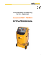
1
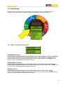
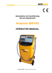
Automotive Air-Conditioning
Service Equipment
Ariazone 5001 FAHD II
OPERATOR MANUAL
1
Contents
Page
1. Introduction........................................................................................................... 3
2. SAFETY FIRST! Important Safety Information's .................................................. 4
3. Technical Features .............................................................................................. 5
4. Main Parts & Features ......................................................................................... 7
5. Preparing the Machine for the First Use .............................................................. 9
6. Printer ..................................................................................................................11
7. Refrigerant Cylinder Filling Procedure ................................................................ 12
8. Connecting to the A/C System ............................................................................ 13
9. Manual Function Selection Procedure ................................................................ 14
9.1. Recovery & Recycling Mode ............................................................................ 15
9.2. Evacuation Mode ...............................................................................................17
9.3. Oil / UV Dye Injection Mode ............................................................................. 18
9.4. Refrigerant Charge Mode ................................................................................. 19
10. Automatic Cycle Selection Procedure ............................................................... 20
11. Cylinder Air Purge ............................................................................................. 23
12. Service Procedure ............................................................................................. 24
13. Unit Settings ...................................................................................................... 25
2
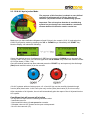
1. Introduction
Ariazone 5001FAHD II - Fully Automatic Air-conditioning (A/C) Service Station is a user-friendly
tool specifically designed for the automotive air-conditioning technicians, to carry out the following
functions:
-
Testing air-conditioning system,
-
Recover and recycling the refrigerant from air-conditioning system,
-
Electronically gauge amount of refrigerant recovered from air-conditioning system,
-
Electronically gauge amount of oil removed from air-conditioning system (if any),
-
Evacuate air-conditioning system,
-
Electronically charge lubricating oil & UV dye by volume into the air-conditioning system,
-
Electronically charge refrigerant into the air-conditioning system by weight.
The unit is a microprocessor control system. This provides electronically controlled functions, whilst
keeping the operator constantly informed and in full control.
This unit has been designed and build to be long lasting and with high level of reliability including
maximum safety for the operator. The operator needs only to be responsible for the proper use and
maintenance of the unit, in accordance with the instructions found in this manual.
This manual contains important information pertinent to operator safety, and must accompany the
unit, in the case of sale or transfer to another party.
Manufacturer reserves the right to modify this manual and the unit itself at any time without prior
notice.
Environmental information
This product may contain substances that can be hazardous to the environmental or to human health if it's
not disposed of properly.
Electrical and electronic equipments should never be disposed of in the usual municipal waste, but must be
separately collected for their proper treatment (recycling).
We also recommend that you adopt appropriate measures for environmental protection: recycling of the
internal and external packaging of the product, including batteries (if any).
With your help it is possible to protect our planet and improve the quality of life, by preventing potentially
hazardous substances being released in to our environment.
3
2. SAFETY FIRST! Important Safety Information's
Ariazone 5001FAHD II unit is extremely simple and reliable in selecting and performing all its
functions. Therefore, the user is not exposed to any risk, if the general safety guidelines reported
below are followed, in association with proper use and maintenance of the unit (improper use and
maintenance will reduce the safety of the unit).
- Read this user manual carefully before operating the unit. If you do not understand any section
of this manual, please contact your nearest distributor or manufacturer.
- This equipment is to be operated by accredited technician only! Users must have basic
knowledge of air-conditioning and refrigeration systems, including potential hazards associated
with the handling of refrigerants and systems under high pressure.
- Handle refrigerant with care as serious injury may occur. Always wear appropriate protective
clothing and safety glasses.
- Avoid inhalation of the refrigerant or oil vapours. Use only in well ventilated work areas.
- Use only pure R134a refrigerant with this equipment.
- Do not expose the machine to direct artificial heat or rain.
- Do not tamper with or change safety control devices or their settings.
- The power cable may only be connected to a socket with nominal voltage stated on the rating
plate, located at the rear of the unit.
- Power lead plug to be connected only to power point with an earth.
- When transporting the unit keep upright and remove refrigerant cylinder from platform.
- Never operate the equipment with a damaged power lead, replace it immediately.
- RISK OF ELECTRICAL SHOCK. Before removing any protective cover from unit, always
unplug power lead from power point.
- Do not cover ventilation openings on chassis cover when the unit is operating.
- Maintenance is to be carried out as per the manufacturer recommendation shown in this manual.
Only Ariazone genuine parts are to be used for maintenance and repairs.
- Maintenance of the unit must only be performed by an authorized technician.
- Only non aggressive substances to be used for cleaning of the unit.
- The unit does not contain or should be operated with flammable refrigerants.
4
3. Technical Features
Refrigerant .......................................... R134a
Electronic refrigerant scale ..................+/- 10 g resolution
Load cell ............................................. 60kg with 150% overload capacity
LP and HP gauges .............................. D 68 mm kl.1.0
Recovery cylinder ................................ 27kg
Recovery pump ................................... FR11G, 275W
Recovery rate ...................................... 400 g/min (liquid state)
Vacuum pump ..................................... 2 stage, 100 l/min (3.5cfm),
Vacuum ............................................... 3 x 10⁻¹ Pa
Dimensions .......................................... 620 mm, 590mm, H-1090 mm
Weight ................................................. 84 kg
Chassis ................................................ Sturdy all steel construction, powder coated
Supply voltage ..................................... 230VAC- 50/60Hz
Power .................................................. 700 W
Max. Currency ..................................... 6.7A
Working conditions .............................. -10 to 55 oC ambient temperature, up to 100% humidity,
2000m altitude
Noise level ......................................... < 70 dB (A).
Fuse……………………………………..10 amp/250V (slow blow type)
Measuring instrument.......................... I category (Not to be mixed with II, III, IV category).
Approvals ........................................... EN 61010-1 Electric safety, EN 55014-1 EMC-CE
5
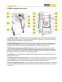
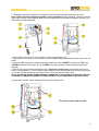
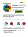
4. Main components location
1. Analogue gauges - Two large analogue gauges display suction and discharge pressures. The
gauges are mounted on the front panel for easy viewing by the operator. Pressures are displayed
in Bar & PSI and temperatures in degrees Celsius.
2. LED & LCD Displays - LED numerical display and LCD display bellow inform the operator on
weight of refrigerant and oil currently in the unit vessels, remaining vacuum time, the amount of
refrigerant and oil being recovered or charged, data base of vehicles and unit set up...
3. LED group and membrane switches (keys). Six LED indicates the mode and status of the
unit. These are used in conjunction with 6 membrane switches (keys) to select the unit functions.
Further, once the mode is in operation the pattern in which the Led’s flash, indicate the activity of
the system. These can be viewed from several metres away.
4. Hand Valves - The console hand manifold valves allows the operator to control the flow of the
refrigerant (if desired).
5. Discharge & Suction Service Hoses - A pair of 3m hoses are connected to the console, which
allows the operator to connect the system to the vehicle air-conditioning system service ports for
testing system pressures, recovering and recharging refrigerant, oil and/or UV dye.
6. Service Hose Quick Couplers - Service hose quick couplers allows the operator to connect the
unit to the vehicle air-conditioning system service ports, without exhausting the refrigerant in to the
environment.
6
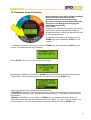
7. Moisture Indicator - The moisture indicator is conveniently mounted below the console for
added protection to indicate the condition of refrigerant and filter change intervals. The following
colours correspond to the following moisture content: Green or Blue Dry, Yellow or Pink Wet.
8. Vacuum Pump Oil Level - Oil level must be checked when the pump is running, the oil level
should be even with the line on the vacuum pump sight glass. Under filling with oil will result in
poor vacuum performance. Overfilling can result in oil blowing out from the vacuum pump exhaust.
9. Recovered Oil Drain Reservoir - A polycarbonate vessel of 250ml is mounted on the right rear
of the unit to electronically gauge the amount of oil recovered from the air-conditioning system, if
any.
10. Oil Storage Reservoir - A polycarbonate vessel of 250ml is mounted on the left rear of the unit
to electronically inject the recovered amount of oil back in to air conditioning system, or to select
the desired amount of oil to be injected.
11. UV DYE Storage Reservoir - A polycarbonate vessel of 250ml is mounted on the lower left
rear of the unit (bellow the Oil Reservoir) to electronically inject UV Dye in to air- conditioning
system.
12. Refrigerant Cylinder - 27kg capacity cylinder is used to store the recovered/recycled
refrigerant. The cylinder is secured by a strap to the platform.
13. Cylinder Non-Condensable Indicator - A large pressure gauge is mounted on the back upper
side of the unit to indicate to the technician of any non-condensable (air) built up in the storage
cylinder.
14. USB port
15. Cylinder Vapour Hose
16. Cylinder Liquid Hose with Ball Valve
17. Brass Adapter
18. Power Lead with Fuse - 10A
19. Power Switch
20. Printer
21. Cylinder Air Purge Ball Valve
7
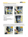
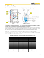
5. Preparing the Machine for the First Use
Perform the following steps to prepare the unit before the first use.
1. Remove the shrink wrap and styrofoam insert behind the cylinder (12) (see figure 1).
2. Check to ensure that all of the accessory
components are with the unit:
-
Cylinder (12)
Adapter (17)
Cylinder vapour hose (blue) (15)
Cylinder liquid hose (red) with ball valve (16)
Service hoses with quick couplers (5)
User's manual
Cylinder strap
3. Check that the cylinder (12) is already placed on the platform and properly secured with the
strap provided. Unscrew two securing M6 bolts situated on each side of the platform base
app. 3-4 mm and LOCK the locking nut, making sure that there is 3mm clearance between the
end of the safety bolt and the base of the machine.
8
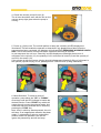
4. Check the vacuum pump oil level (8).
The oil level should be even with the line on the
vacuum pump sight glass when the pump is
running.
5. Power up (19) the unit. The unit will perform a lamp test, whereby all LED displays are
illuminated. This will enable the operator to determine if any displays have failed. After the
sequence has been completed, the displays will indicate FILT, REMAINING WORKING HOURS
99Hr. This is the number of hours left before equipment servicing is required.
In next sequence the unit is on "Stand by" and the displays are showings the amount of
refrigerant in the cylinder (12), the quantity of oil in recovered oil vessel (9) and the quantity of
new oil in the vessel (10).
If the cylinder is delivered empty, display should indicate approximately 0.00kg of refrigerant in
the cylinder,(cylinder empty). If not, please perform TARE function (0.00kg calibration).
6. Mode Selection. To select a mode of
operation, press either the "UP" or "DOWN"
arrow keys until the LED indicator is beside the
desired function. Press 'START' key which will
cause the unit to enter the selected mode. Any
mode that has been selected can be exited by
pressing the 'STOP' key.
Note, that if a valid key was depressed, the unit
will beep. If an inappropriate selection has been
made, i.e. attempting to select a mode whilst
another mode is in operation, the unit will
ignore the pressed key and will not beep.
9
7. Refrigerant cylinder (12) fitted on a platform is evacuated during the production process.
Note, please check if refrigerant cylinder (12) is evacuated (during transport, vacuum could be
lost). If the vacuum is lost, please perform the following steps to evacuate refrigerant cylinder (12)
before filling it with refrigerant:
- Connect blue service hose (5) to cylinder (12) by using adaptor (17).
- Open cylinder (12) valve, service hose (5) quick coupling and manifold hand wheel (4) on the unit
panel.
- Press the 'UP" key twice to select evacuation function. Press "START" and with the "UP" and
"DOWN key select 30 minutes. Press "START" key again and the unit will start the evacuation
process.
- After 30 min. the unit will automatically stop. Close the cylinder valve, disconnect the service
hose (5) and adapter (17) from cylinder, place adaptor on the storage port and connect liquid hose
(16) to the cylinder liquid port and vapour hose (15) to the cylinder vapour port.
NOTE, LIQUID AND VAPOR HOSES MUST BE CONNECTED TO VAPOR AND LIQUID PORTS ON THE
STORAGE CYLINDERS. INCORRECT CONNECTION WILL CAUSE CHARGING TO BE VERY SLOW.
8. Open both cylinder valves and open liquid hose (16) ball valve.
The unit is now ready for use.
10
6. Printer
The printer is equipped with two keys and green
led:
>> Paper feed
II on line / off line
The green led shows the state of the printer:
Led constantly ON - Printer in line
Led blinking - Printer not in line or no paper
Led off - Press II. If the problem persists,
contact authorized distributor or manufacturer.
Printer roll specifications,
Paper width: 57-58mm
Max paper thickness: 80 µ
Printing report:
After completion of every operation the unit will
print a report as per list on the right --->
11
7. Refrigerant Cylinder Filling Procedure (Refrigerant Transfer)
The cylinder (12) may be filled with refrigerant by the following procedures.
a. Using refillable cylinder procedure
Have the cylinder sitting upright, connect the suction (blue) service hose (5) to storage cylinder
liquid valve by using the refrigerant cylinder adapter (17), open liquid valve on storage cylinder,
open service hose quick coupling (5) and console blue hand valve (4) >>>
b. Using disposable cylinder procedure
Connect the suction (blue) service hose (5) to a storage cylinder valve by using the refrigerant
cylinder adapter (17). Turn cylinder upside down for liquid delivery, open the valve on the storage
cylinder, open service hose quick coupling (5) and console blue hand valve (4) >>>
>>>
Press "DOWN" key twice to select the REFRIGERANT
TRANSFER function and press "START". With "UP" or
"DOWN" keys select between TOTAL TRANSFER (all) or
PARTIAL TRANSFER (set the amount of refrigerant to be
transferred). Press "START" key and unit will automatically
transfer the selected amount of refrigerant from storage
cylinder to the unit cylinder (12).
When the selected amount of refrigerant is transferred, close
the storage cylinder valve and allow the unit to recover the
refrigerant from the service hose (5). Once the function is
completed the unit will display symbol "DONE" and the
amount of refrigerant transferred will be displayed in kg or lb
on main display (2).
Important:
- Always keep a minimum of 2 kg in the cylinder (12).
- Do not allow the cylinder (12) to be filled above 80% capacity.
- Never transport an overfilled cylinder. Refrigerant expands when heated and may cause
the pressure relief valve to open and exhaust refrigerant in to the atmosphere or the
cylinder may rupture.
12
8. Connecting to the A/C system
Use the service hose (5) quick-connect couplers to connect the hoses to the A/C system service
ports, bearing in mind that BLUE must be connected to the low-pressure (suction) side and RED
to high pressure (discharge) side.
If the system is equipped with a single service port, connect only the relative hose.
Note: Before connecting the quick couplers, clean the a/c ports of any foreign material.
Winding the quick coupler hand wheel clockwise, will allow the refrigerant to flow through the
hoses. Turning hand wheel in opposite direction, the flow will be closed. If there is any refrigerant
in the air-conditioning system, the pressure gauges will indicate a pressure rise.
Important: Console manifold hand valves (4) need to stay closed, NOT to allow refrigerant
to enter into the unit until the required function has been selected.
The unit gauges (suction & discharge) are important and useful instruments.
The operator should have basic understanding between gauge reading and air-conditioning system
operation, in order to correctly diagnose any possible system malfunction.
13
9. Manual Function Selection Procedure
With this procedure, all functions (Refrigerant Recovery & Recycling, Recovered Oil Drain,
A/C System Evacuation, New Oil and/or UV Dye Injection and Refrigerant Charge) can be
performed individually (step by step).
The values for the quantity of refrigerant recovered, quantity of the oil recovered, vacuum time,
quantity of oil injected and quantity of refrigerant charged into the a/c system are automatically
printed at the end of each single operation.
14
9.1. Recovery & Recycling Mode
The purpose of the Recovery & Recycling mode is to
recover refrigerant from the air conditioning system,
which will condense, purify and store the liquid
refrigerant in the storage cylinder ready for re-use.
To initiate the Recovery mode, press the 'UP' key once,
followed by 'START' on the console. Display will show:
1. TOTAL RECOVERY to recover the whole amount of the refrigerant from the A/C system or
storage cylinder.
2. PARTIAL RECOVERY to select desired quantity of refrigerant to be recovered from the a/c
system or storage cylinder. After the quantity selection is made, press "START" key.
Note: Open the hand manifold valves (4) on the console to allow the flow of the refrigerant
from the a/c system before making the above selection (valves on the unit storage cylinder
(12) and ball valve on the cylinder liquid hose (16) must be open also).
During the recovery process, the 'Recovery' mode LED indicator will blink and the display (2) will
indicate the amount of refrigerant being recovered.
In normal operation the above condition will be maintained until a vacuum of -0.4 bar is reached at
either the discharge or suction ports. When this occurs, the machine will beep once, and the unit
will enter in Recovery "PAUSE" mode. In this mode, the unit will shut down the Recovery function
and pause for 180 seconds, in which during this time the recovery mode enunciator will be ON
constantly. The display (2) will indicate "PAUSE". During this function, the unit is monitoring
whether the air-conditioning system pressure is increasing, due to any refrigerant that may be left
in the accumulator or dryer. If the pressure increases above zero, the machine will re-start the
recovery function automatically and recover the remaining refrigerant.
If at the end of Recovery process a sufficient vacuum of -0.4 Bar has been maintained, the unit will
stop, and the display (2) will indicate 'DONE' and the amount of refrigerant recovered will be
displayed in kg (or lb) depending on the operator’s selection.
Press 'STOP' on the console, the unit will display "busy" for 5 seconds.
The value of the quantity of refrigerant recovered will be automatically printed.
15
Recovered Oil Drain
After completing the recovery function, the unit will automatically drain the recovered oil (if any) into
recovered oil vessel (9) to electronically calculate amount of oil that has been recovered. The value
of the recovered oil will be automatically printed.
Conditions that will halt the recovery mode
The above sequence assumes that neither the stop button was pressed, or that no undesirable
condition occurred. The following conditions will cause the unit to halt the recovery function.
1. Refrigerant cylinder (12) full. To protect the storage cylinder from being overfilled, the unit will
not allow the operator to recover refrigerant once it has reached 80% of its capacity. “CYL FULL”
will be displayed.
2. Air conditioning system empty. If the A/C system pressure is not above atmospheric
pressure, the recovery function will not be activated. “NO REF” will be displayed.
3. High Pressure. If the operating pressure of the unit exceeds 25 bar (340 PSI), the unit will stop
and display 'H-PRES'. The following can cause the above:
• Cylinder (12) valves not open.
• Restricted cylinder hose (16). Check the ball valve.
• Excessive high ambient temperatures.
• Excessive air in refrigerant cylinder (12).
• Faulty pressure control
In all the above circumstances, press the 'STOP' key to return to the machines initial mode.
If the above conditions are ok and the ‘H-PRES’ display keeps on appearing, contact your local
distributor or manufacturer for further advice.
16
9.2. Evacuation Mode
In the evacuation mode the air and moisture in the air
conditioning system is removed and exhausted to the
atmosphere. The evacuation mode runs for a
predetermined time selected by the operator.
To initiate evacuation mode, press the 'UP' key twice,
followed by the 'START' key. Select the desired
evacuation duration by pressing the 'UP' key to increase
or ‘DOWN’ key to decrease time duration. Once the
desired time has been selected, press the 'START' key
and the function will commence.
The evacuation time can be set from one minute to eight
hours.
Note: During evacuation mode the manifold hand valves (4) on the console must be open.
At any time the evacuation time can be paused or cancelled by pressing the stop button once to
pause, or twice to cancel the function.
Note: The unit has a unique function that if the evacuation function is selected and there is residual
refrigerant in the air conditioning system, greater then 0.5 Bar (10 PSI), the unit will detect this
condition, whereby it will beep six times to warn the operator. After this warning the unit will
automatically recover the residual refrigerant, once it has recovered the entire refrigerant it will start
the selected evacuation function automatically.
LEAK TEST
If the vaccum of min -0.85 Bar is not reached after first 90sec, the unit will beep and display TEST
FOR LEAK, indicating for possible leak in the a/c system or bad connection of the service hoses.
After completion of evacuation function, next 3 minutes the unit will test if there is leak in the a/c
system. Depends if the a/c system is leaking or not, the display will show OK or FAILED.
After completion of evacuation function, the unit will automatically print the report.
17
9.3. Oil & UV dye Injection Mode
The purpose of this function is to batch a user-defined
quantity of refrigerant oil or UV dye from the oil
reservoir (10) to the vehicle air-conditioning system.
Important: The unit requires that the air conditioning
system has previously been evacuated to a maximum
vacuum before this function can be carried out.
Make sure you have sufficient refrigerant oil and UV dye in the vessels (10 & 11) and select the
Oil/UV Dye Injection mode by pressing the 'UP’ or ‘DOWN' keys, followed by the 'START' key.
Now the display will shows the following:
Select the desired amount of refrigerant oil ('UP' key to increase or ‘DOWN’ key to decrease the
volume). With "> key go to UV DYE and again with "UP & DOWN" keys select the desired number
of UV Dye doses (1 dose ~7ml).
Once the desired amount has been selected press the 'START' key and open only the discharge
(Red) hand manifold valves (4) on the console.
(On A/C systems without discharge port, ref. oil and UV dye can be carefully injected through
suction (blue) hand valve .in this case open only suction (blue) hand valve (4) on the console)
After completion of oil injection, the unit will automatically print the report of the oil injected into the
A/C system.
Conditions that will prevent oil injection
The unit will not inject oil if the following conditions exist:
- Insufficient vacuum.
- Hand manifold valves (4) not opened on console.
- Schrader valve on A/C system service port not depressed.
- No oil in the reservoir (10).
18
9.4. Refrigerant Charge Mode
The purpose of the refrigerant charge mode is to batch
a user-defined weight amount of refrigerant into the airconditioning system.
Important: It is recommended that the A/C system is
always properly evacuated and leak tested, before
refrigerant is charged in to the A/C system.
To initiate charging mode, press the 'UP' key four times,
followed by the 'START' key. The display will shows the
following
Select the desired charging mode MANUAL or FROM DATABASE and set the amount of
refrigerant to be charged into the a/c system (with 'UP' key to increase or ‘DOWN’ key to decrease
in manual mode, or by selecting the vehicle make and model from database). The smallest
increment of refrigerant charge weight is 0.01 kg (if the units of weight are to lb the smallest
increment of refrigerant charge weight is 0.02lb).
Holding the 'UP' or 'DOWN' keys for longer than two second will cause the increments of weight
change to increase or decrease rapidly.
Once the refrigerant charge weight has been set, press the 'START' key and open appropriate
hand manifold valve depending on whether you are charging with the engine running or engine
stationary (if the A/C system is OFF or ON).
Once the present refrigerant weight has been charged, the charge function will automatically stop
and the display will indicate 'DONE'. The operator can return the machine to its initial state by
pressing 'STOP' key on the console.
After completion of refrigerant charge, the unit will automatically print the report of the amount of
refrigerant charged into the A/C system.
Conditions that will prevent refrigerant charging
- If there is little or no refrigerant in cylinder (12). The operator will not be able to select the
desired amount of refrigerant required.
- If the cylinder (12) valve is closed.
- If the hand manifold valve (4) is closed.
- If the A/C system service port Schrader valve is not depressed
19
10. Automatic Cycle Procedure
In the Automatic cycle mode, all the operations
will be performed one after the other.
(Refrigerant Recovering and Recycling,
Recovered Oil Drain, System Evacuation, New
Oil Injection and Refrigerant Charging) are
performed automatically,
in one cycle.
Quantity of the refrigerant recovered, recovered oil,
vacuum time, new oil injected and refrigerant
charged into the A/C system are printed at the end
of each single operation.
To initiate the Automatic cycle mode, press the
'DOWN' key once, followed by 'START' on the
console.
To initiate the Automatic cycle mode, press the 'DOWN' key once, followed by 'START' on the
console. The display will show the following:
Press "START" button to confirm the recovery function.
By pressing the 'UP' key to increase or 'DOWN' key to decrease select the desired Evacuation
Time Duration. Once the desired time has been selected, press the 'START' key.
Oil/UV Dye injection. The operator can choose between:
- AUTOMATIC oil injection. The unit determines the quantity of oil extracted during the recovery
process and will inject the same quantity back in the a/c system. The quantity of UV dye can be
selected also.
- MANUAL, with 'UP' key (to increase) or "DOWN" key (to decrease) select the amount of
refrigerant oil and/or UV dye to be injected into the a/c system. ">" and "<" key to change oil or
UV Dye selection. Once the desired amount has been selected, press the 'START' key.
20
Select the desired charging mode, MANUAL or DATABASE and set the amount of refrigerant to be
charged into the a/c system (with 'UP' key to increase or ‘DOWN’ key to decrease in manual mode
or by selecting the vehicle make and model from database). The smallest increment of refrigerant
charge weight is 0.01 kg (if the units of weight are to lb the smallest increment of refrigerant charge
weight is 0.02lb). Holding the 'UP' or 'DOWN' keys for longer than two second will cause the
increments of weight change to increase or decrease rapidly.
Once the refrigerant charge weight has been set, open both hand manifold valves and press the
'START' key. Note: A/C system must be OFF.
The unit will perform all tasks in one automatic cycle and will print reports at the end of each single
operation.
21
Conditions that will prevent automatic cycle procedure
a) If the vacuum test failed.
If the vaccum of min -0.85 Bar is not reached after first 90sec of evacuation process, the unit will
beep and display TEST FOR LEAK, indicating for possible leak in the a/c system or bad
connection of the service hoses.
After the evacuation process is completed, the unit is testing of any possible vacuum leak that may
exist in the air-conditioning system. After 180 sec, if the a/c system is NOT holding the vaccum the
display will show FAILED and the unit will not charge the a/c system.
b) If there is little or no refrigerant in cylinder (12). Display shows "ADD REF". The operator must
add refrigerant into unit cylinder (12).
c) If the recovered oil vessel (9) is full, and display will show "OIL FULL". The operator must
empty the recovered oil vessel. Dispose of used oil properly.
Note: If the recovered oil vessel becomes full during the oil drain, the process will be stopped.
Display will show "OIL FULL". Operator must empty the vessel and press "STOP". The automatic
cycle will then continue.
d) If new oil vessel (10) is empty display will show "ADD OIL". The operator must fill the oil vessel.
Note: During the process of oil injection, if there is insufficient oil in the new oil vessel (10), the
display will show "ADD OIL". The operator must add the oil in the vessel and press "STOP". The
automatic cycle will then continue.
e) If the refrigerant cylinder (12) is full. To protect the storage cylinder from being overfilled, the unit
will not allow the operator to recover refrigerant once it has reached 80% of its capacity.
f) If the hand manifold valve (4) console are closed.
g) If the A/C system service port Schrader valve is not depressed
h) High Pressure. If the operating pressure of the unit exceeds 25 bar (340 psi), the unit will stop
and display 'H- PRES'. The following can cause the above:
•
•
•
•
•
•
Cylinder (12) valves not open.
Restricted cylinder hose (16). Check the ball valves.
Excessive high ambient temperatures.
Excessive air in refrigerant cylinder.
Faulty pressure control
Recovery pump thermo control faulty.
In all the above circumstances, press the 'STOP' key to return to the machines initial mode.
If all the above conditions are OK, contact your local distributor of manufacturer for further advice.
22
11. Cylinder Air Purge
Once a week check if there is non-condensable (air) build up in the refrigerant cylinder.
First, measure the ambient temperature. Then read the cylinder pressure on rear gauge (13) and
compare it with the temperature pressure chart, affixed to the machine.
If the cylinder pressure is higher than the pressure/temperature chart, there are non-condensable
gases (air) in the cylinder (12). Slightly OPEN ball valve (21) to purge the non-condensable gases
(air) from the cylinder (12) and bring back the pressure to the recommended chart values.
Note: After recovery process it is normal that cylinder pressure is higher than the
pressure/temperature chart shows. Always read the cylinder pressure gauge (13) first thing
in the morning before operating the machine.
Example: Ambient temp. 20 oC, the cylinder pressure should be 4.7 bar.
Ambient temperature
(Co)
8
12
18
20
22
24
26
28
30
34
38
42
46
50
Air purge gauge readings
bar
PSI
2.9
42
3.4
49
4.3
63
4.7
68
5.1
73
5.4
79
5.8
84
6.2
90
6.7
96
7.6
110
8.6
124
9.7
14.1
10.9
157
12.1
175
23
12. Service Procedure
The following table describes the service intervals of the unit.
Every 100 Working Hours /Once a Year Service.
The service alarm will alert the operator for maintenance and filter replacement.
Interval
Every 100 Hr / Once a year
Every 100 Hr / Once a year
Every 100 Hr / Once a year
Every 100 Hr / Once a year
Every 100 Hr / Once a year
Every 100 Hr / Once a year
Component
Main Filter Dryer
Primary Recovery Line Filter
Vacuum Pump Oil - 330ml
Service hose "O" rings
Gauges
Weight Platform
Procedure
Replace
Replace
Drain and refill
Check / Replace
Test calibration
Test calibration
Service Kit 100Hr
(Vacuum pump Oil - 330ml x 2 , Recovery Line Filter,
Main Filter Dryer, Service Hoses "O" rings)
Art. No: 000828
Every 300 Working Hours Service.
The unit requires 100 hour service plus replacing of oil separator, primary charging filter and
recovery pump (compressor) oil.
Interval
300 Hours
300 Hours
300 Hours
300 Hours
300 Hours
300 Hours
300 Hours
300 Hours
300 Hours
Component
Oil Separator
Primary Charging Line Filter
Recovery Pump Oil - 400ml
Main Filter Dryer
Primary Recovery Line Filter
Vacuum Pump Oil - 330ml
Service hose "O" rings
Gauges
Weight Platform
Procedure
Replace
Replace
Drain and refill
Replace
Replace
Drain and refill
Check / Replace
Test calibration
Test calibration
Service Kit 300Hr
(Vacuum Pump Oil - 330ml x 2 , Recovery Line Filter,
Main Filter Dryer, Service Hoses "O" rings, Charging
Line Filter, Oil Separator, Recovery Pump Oil -500ml)
Art. No: 000829
Manufacturer recommends a record of all services on the machine to be kept.
Note: Always wear appropriate protect clothing and safety glasses when servicing the
machine.
24
13. Unit Settings
Switch ON the unit with the main power switch, while holding "STOP" key depressed for. 5
seconds. The unit will enter in setup mode and the display will show the following:
13.1. Setup Tare (00.00kg calibration)
REFRIGERANT SCALE (Calibrating the weight display to read 00.00kg with an empty cylinder on the unit platform)
Place standard empty cylinder or calibrated weight on the cylinder platform, making sure that
cylinder hoses are resting on calibrated weight or cylinder. When ready, press "START" key to
confirm. The unit display should show app. 0.00 kg.
RECOVERED. OIL SCALE (Calibrating the weight display to read 00.00ml when recovered oil vessel (9) is empty)
Place empty polycarbonate vessel on recovered oil (9) load cell. When ready, press "START" key
to confirm. The unit display should show app. 00.00 ml.
NEW OIL SCALE (Calibrating the weight display to read 00.00ml when new oil vessel (10) is empty)
Place empty polycarbonate vessel on new oil (10) load cell. When ready, press "START" key to
confirm. The unit display should show app. 00.00 ml.
25
13.2. Setup Span (weight calibration)
REFRIGERANT SCALE - (Calibrating the refrigerant cylinder (12) electronic scale)
Add an additional etalon weight of 20 kg on the standard empty cylinder. Use "UP" or "DOWN"
key to move span until display shows the value of additional etalon weight added. Press "START"
key to exit and save.
RECOVERED. OIL SCALE - (Calibrating the recovered oil vessel (9) electronic scale)
Add 200ml of oil into the recovered oil vessel (9). Use "UP" or "DOWN" key to set the correct
weight of 200ml (the display (2) should indicate the weight of 0.200 ml). Press "START" key to
lock in correct weight and exit.
NEW OIL SCALE - (Calibrating the new oil vessel (10) electronic scale)
Add 200ml of oil into the new oil vessel (10). Use "UP" or "DOWN" key to set the correct weight of
200ml (the display (2) should indicate the weight of 0.200 ml). Press "START" key to lock in
correct weight and exit.
13.3. Cylinder Settings
MAX. REFRIGERANT WEIGHT - Set up of max allowable refrigerant weight in
cylinder (12)
Use "UP" or "DOWN" keys to set the cylinder weight to 80% of its capacity (22kg max. for 27kg
cylinder). Press “START” to save the above settings.
MAX. RECOVERED OIL AMOUNT - Set up of maximum recovered oil level in vessel (9)
Use "UP" or "DOWN" keys to set maximum recovered oil level in vessel (9). Set to140ml. Press
“START” to save the above settings.
MINIMUM REFRIGERANT. WEIGHT- Set up of minimum refrigerant weight into cylinder (12)
Use "UP" or "DOWN" keys to set maximum refrigerant weight into cylinder (12). Set
minimum weight to 3kg. Press “START” to save the above settings.
26
13.4. Working Hours Reset
After the system has been completely serviced in according to manufacturer's specifications reset
the filter replacement interval on new 99 working hours. Enter PIN code (4 numbers) and press
"START".
13.5. Relays testing
R1 - Vacuum Pump,
R2 - Recovery Pump,
R3 - Recovery Solenoid Valve,
R4 - New Oil injection Solenoid Valve,
R5 - Recovered Oil Solenoid Valve,
R6 - UV Dye Injection Solenoid Valve,
R7 - Charge Solenoid Valve,
R8 - Air Purge Solenoid Valve,
13.6. Pre-charge (Set the pre-charge value)
Set the pre-charge value in order to compensate refrigerant that during the charging process stays
trapped into the service hoses. Minimum 00.01kg.
13.7. Refrigerant Management
The operator can read total recovered weight, total charge weight and total refrigerant transfer.
13.8. Set the Language
13.9. Time & Date
13.10. Kg or Lb
13.11. Advanced Settings - Manufacturer area only
27
Notes:
D E C L A R A T I O N OF C O N F O R M I T Y
The company: Ariazone International Europe
15-ti Korpus bb.,
6000 Ohrid,
MACEDONIA
Hereby declares that the product:
Ariazone 5001FAHD - Automotive A/C Service Station
Meets all requirements of European Directives:
2006/95/EC (ex 73/23/EEC) Low Voltage Directive
2004/108/EC Electromagnetic Compatibility
98/37/EC Machine Directive
and subsequent amendments entered in force to the date of declaration.
The following standards and technical specifications, conforming to EEC Harmonized
Regulations were applied:
EN 61010-1:2001 with cross references: EN 60227, EN 60245, EN 60309:2003;
EN 60799, EN 60804, EN 60825-1
EN 55014-1; EN ISO 12100-1; EN ISO 12100-2;
EN ISO 12100-1:2003; EN ISO 12100-2:2003
The producer also declares that equipment confirms Directives and Standards when used
according to manufacturer specifications.
Date and place of issuing:
Ohrid, ______________
Serial No: __________
Ariazone International
Tullamarine, Victoria
Ph.: (03) 9464 5688
Mob.: 0419 321 774
www.ariazone.com
Ariazone International - Europe
www.ariazone.com.mk
Made in Macedonia
28