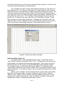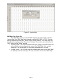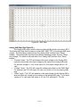
1
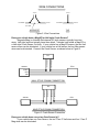
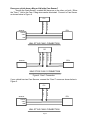
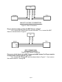
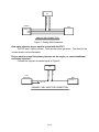
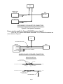
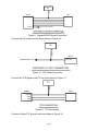
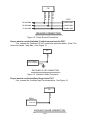
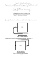
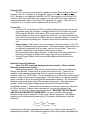
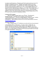
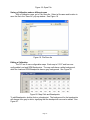
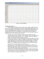
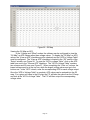
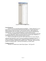
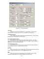
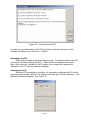
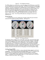
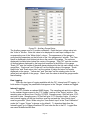
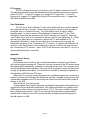
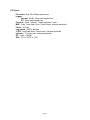
Installation Instructions for
30-1910
Fuel Ignition Controller (F/IC)
,!
WARNING:
This installation is not for the electrically or mechanically
challenged! Use the F/IC with EXTREME caution! If you are
uncomfortable with anything about this, please refer the
installation to an AEM trained tuning shop or call 800-423-0046
for technical assistance. You should also visit the AEM
Performance Electronics Forum at http://www.aempower.com
NOTE: AEM holds no responsibility for any engine damage that
results from the misuse of this product!
This product is legal in California for racing vehicles only and should
never be used on public highways.
ADVANCED ENGINE MANAGEMENT INC.
th
2205 126 Street Unit A, Hawthorne, CA. 90250
Phone: (310) 484-2322 Fax: (310) 484-0152
http://www.aempower.com
Instruction Part Number: 10-1910 Rev 080609
© 2007 Advanced Engine Management, Inc.
Page 1
Thank you for purchasing the AEM F/IC. Inside the box you will find the F/IC
module, a universal wiring harness, a software CD, and other components needed to
install the F/IC and adjust the FIC via a laptop or PC. See Figure 1. For more
information on select vehicles, please visit the FIC section of the AEM Electronics
Forum. The forum can be accessed from the AEM homepage (www.aempower.com),
by clicking on the link titled “Forums”.
Kit Contents:
* F/IC Module
* Flying Lead Harness
* Bypass plug
* Instructions
* Software CD
* USB Cable
* Vacuum Hose (3 Ft)
* Tee Fitting
* Zip Tie (3)
Figure 1. Kit Contents
Getting started
(Note: The following is a universal wiring installation. For more specific
information on some of the more common vehicles, please visit the FIC section of the
AEM Electronics Forum. Also, to make the install easier and to save you from cutting
your factory harness, we recommend the use of a “patch” or “extension” harness.
These harnesses are readily available from companies like Boomslang
(http://www.boomslang.us/) or Auto Sport Wiring (http://www.autosportwiring.com/).)
The first step in connecting the F/IC is to determine what features/functions are needed
and which functions are not needed. The F/IC comes with a universal flying lead that
has 46 non-terminated wires. At first glance, the bundle of wires is quite intimidating.
However, by answering some questions about your vehicle and what you want to do
with the F/IC, some of the wires can be eliminated. Before we begin, we must learn the
two types of connections used with the F/IC: the tap and the intercept. See Figure 2.
T
Page 2
WIRE CONNECTIONS
TO FIC
TO FIC
TO ENGINE
TO ENGINE
TO ECU
TO ECU
CUT WIRE
INTERCEPT
TAP
Figure 2. Wire Connections
Does your vehicle have a Mag/VR or Hall style Crank Sensor?
Magnetic(Mag) or Variable Reluctance(VR) style sensors typically have two
wires. Hall style sensors typically have three wires. Vehicles have either a Mag/VR or
a Hall style Crank Sensor, not both. If your vehicle has a Mag/VR sensor, the two Hall
sensor wires can be eliminated. If your vehicle has a Hall sensor the four Mag sensor
wires can be eliminated. Connect the Crank Sensor as shown below in Figure 3.
FIC
CRK HALO +
CRK HALI +
SENSOR
ECU
SIGNAL
VREF
GND
HALL STYLE CRANK CONNECTION
FIC
CRK MAGO +
CRK MAGO -
CRK MAGI -
CRK MAGI +
SENSOR
ECU
+
-
MAG STYLE CRANK CONNECTION
Figure 3. Crank Sensor Connection
Does your vehicle have one or two Cam Sensor(s)?
If your vehicle has one Cam Sensor, the two “Cam 2” Hall wires and four “Cam 2”
Mag wires can be eliminated.
Page 3
Does your vehicle have a Mag or Hall style Cam Sensor?
As with the Crank Sensor, a vehicle will have one or the other, not both. Either
the “Cam 1” Hall or the Cam 1 Mag wires can be eliminated. Connect to Cam Sensor
as shown below in Figure 4.
FIC
CAM1 HALO +
CAM1 HALI +
SENSOR
ECU
SIGNAL
VREF
GND
HALL STYLE CAM 1 CONNECTION
FIC
CAM1 MAGO +
CAM1 MAGO -
CAM1 MAGI -
CAM1 MAGI +
SENSOR
ECU
+
-
MAG STYLE CAM 1 CONNECTION
Figure 4. Cam 1 Connection
If your vehicle has two Cam Sensors, connect the “Cam 2” sensor as shown below in
Figure 5.
FIC
CAM2 HALO +
CAM2 HALI +
SENSOR
SIGNAL
VREF
GND
HALL STYLE CAM 2 CONNECTION
Page 4
ECU
FIC
CAM2 MAGO +
CAM2 MAGO -
CAM2 MAGI -
CAM2 MAGI +
SENSOR
ECU
+
-
MAG STYLE CAM 2 CONNECTION
Figure 5. Cam 2 Connection
Do you want to modify or clamp the MAF Sensor voltage?
If not, the two MAF Sensor wires can be eliminated. If so, connect the MAF
Sensor as shown below in Figure 6.
FIC
MAF OUT +
MAF IN +
SENSOR
ECU
SIGNAL (+)
VREF
GND
MAF CONNECTION
Figure 6. MAF Sensor Connection
Does your vehicle have both a MAP Sensor and a MAF Sensor? or Do you want to
remap another analog signal on your car?
If so, connect the “Analog A/B” wires as shown below in Figure 7. If not, remove
the unused wires for “Analog A/B”.
Page 5
FIC
ANALOG A/B OUT +
ANALOG A/B IN +
SENSOR
ECU
SIGNAL (+)
VREF
GND
ANALOG A/B CONNECTION
Figure 7. Analog A/B Connection
How many Injectors do you want to control with the F/IC?
The F/IC has 6 Injector drivers. There are two wires per driver. The wires for the
unused drivers can be eliminated.
Do you want to control the primary Injectors on the engine, or control additional
secondary Injectors?
Connect the injectors as shown below in Figure 8.
FIC
INJ 1 IN
INJ 1 OUT
FUEL
INJECTOR 1
ECU
FUEL INJ 1
TO +12V
PRIMARY FUEL INJECTOR CONNECTION
Page 6
FIC
INJ 1 OUT
INJ 1 IN
PRIMARY FUEL
INJECTOR 1
ECU
FUEL INJ 1
TO +12V
SECONDARY
FUEL INJECTOR 1
TO +12V
SECONDARY FUEL INJECTOR CONNECTION
Figure 8. Fuel Injector Connection
Do you want to modify the Oxygen(O2)/UEGO sensor signals?
If not, the “O2” sensor wires can be eliminated. If so, connect the sensors as
shown below in Figure 9
.
FIC
O21 +
SEE RESISTOR DETAIL
SENSOR
ECU
SIGNAL
HEATER
POWER
TO FACTORY HARNESS
SIGNAL GND
NARROW BAND O2 SENSOR CONNECTION
RESISTOR DETAIL
WRAP BARE WIRES
AROUND RESISTOR LEADS
SOLDER
TO NARROW BAND O2 SENSOR
TO ECU
SOLDER
1K 1/4W RESISTOR
TO NARROW BAND O2 SENSOR
TO ECU
APPLY SHRINK TUBING
AFTER SOLDERING
TAP CONNECTION MUST BE
ON ECU SIDE OF RESISTOR
TO FIC
Page 7
FIC
O21 +
SENSOR
ECU
NERNST CELL
POWER
TO FACTORY HARNESS
WIDE BAND O2 SENSOR CONNECTION
Figure 9. Oxygen/UEGO Sensor Connection
Connect the F/IC power wire as shown below in Figure 10.
FIC
IGN PWR
TO SWITCHED +12V
ECU
SW +12V
SWITCHED +12 VDC CONNECTION
Figure 10. F/IC Power Connection
Connect the TPS signal to the F/IC as shown below in Figure 11.
FIC
TPS +
ECU
SENSOR
SIGNAL
VREF
GND
TPS CONNECTION
Figure 11. TPS Connection
Connect all three F/IC grounds as shown below in Figure 12.
Page 8
FIC
SIG GND
PWR GND
PWR GND
ECU
TO GROUND
POWER GND
TO GROUND
POWER GND
TO SIG GND
SIGNAL GND
GROUND CONNECTION
Figure 12. Power Ground Connections
Do you want to use the Switched 12 volt dc source from the F/IC?
If so, connect the “Switched 12 Volt” source wire as shown below. (Note: The
driver can handle 1 amp Max.) See Figure 13.
FIC
SW12
LOW CURRENT
RELAY/SOLENOID
SWITCHED 12 VDC CONNECTION
Figure 13. Switched 12Vdc Connection
Do you want to use the Auxiliary Gauge in the F/IC?
If so, connect the “Auxiliary Input” as shown below. See Figure 14.
FIC
AUX IN
UEGO
0-5V OUT
AUXILIARY GAUGE CONNECTION
Page 9
Figure 14. Auxiliary Gauge Connection
Do you want to use the F/IC’s Internal Data Logger or the Dual Calibration mode?
If so, connect the “Switch Input” as shown below in Figure 15.
Figure 15. Switch Input Connection
Connect the “Boost Line” to manifold pressure (After Throttle Body) as shown below in
Figure 16.
FIC
TO MANIFOLD PRESSURE
BOOST LINE CONNECTION
Figure 16. Boost Connection
Connect the F/IC to the PC using the supplied USB cable. See Figure 17.
TO USB PORT
FIC
USB PORT CONNECTION
Figure 17. USB Com Cable Connection
Page 10
Using the F/IC
The F/IC is a very unique product, capable of precise Fuel and Ignition Control.
However, the F/IC, by design, is a “piggyback” engine controller, not a stand-alone
ECU. Because it is a piggyback controller, the F/IC relies heavily on the factory ECU.
As factory ECU’s get more and more complex, it is more difficult to sustain improved
engine performance without the factory ECU “detuning” the engine. Thus, the key to
using the F/IC is to make it work in harmony with the factory ECU.
Tuning Tips
• Tune the F/IC so the factory’s ECU’s closed-loop fuel trims are as close to zero
as possible using the fuel maps. Change the factory ECU’s closed loop target
AFR using the O2 table. Most factory ECU’s can sense extra fuel and will
promptly adjust the fuel trims to remove the extra fuel. For easy reference, fuel
trims can be monitored with an OBDII scanner or equivalent device. Positive fuel
trims are reduced by adding fuel. Negative fuel trims are reduced by removing
fuel.
• Keep it simple. Many times it is not necessary to use every function of the F/IC
to obtain the desired engine performance. If the desired engine performance can
be achieved by adjusting only two maps, use only the two maps. There is no
benefit to adding fuel in one map and removing it in another.
• Be conservative when making changes. A small step in the wrong direction is
less likely to damage an engine than a large step in the wrong direction.
• Use the Oxygen Sensor functions only when additional closed-loop fuel is
needed.
Absolute Pressure Explained
(Note: The F/IC reads and displays absolute pressure. Please read the
following section before tuning.)
When talking pressure, there are two common ways pressure is represented,
Gauge, and Absolute, Gauge being by far the more common way. Take a tire for
example, if the measuring gauge says 50 psi, we say the tire has 50 psi of air in it.
However, that is not 100% correct. The tire actually has air at 50 psi above atmospheric
pressure, which is known as psi gauge (psig). The total pressure, or absolute pressure
(psia) is actually 50 psi on the gauge plus the atmospheric pressure. So, the absolute
pressure is the gauge pressure plus the atmospheric pressure. What about boost
gauges? Most boost gauges display gauge pressure both above and below
atmospheric pressure. Pressure above atmospheric pressure is commonly referred to
as ”Boost” pressure. Pressure below atmospheric is commonly referred to as
“Vacuum”. So why the lesson on absolute pressure? BECAUSE THE F/IC READS
AND DISPLAYS ABSOLUTE PRESSURE!!! For easy reference, the following
formulas can be used to determine, “Boost” and “Vacuum’ pressures. Atmospheric
pressure can be determined by reading the F/IC pressure with the key on and the
engine off.
P(boost) = P(F/IC) – P(atmospheric)
P (vacuum) = P(atmospheric) – P(F/IC)
Now that you’re starting to grasp absolute pressure, you might wonder why the F/IC
reads absolute pressure. Well, absolute pressure is the only accurate, repeatable way
Page 11
to measure manifold pressure. Measuring only “Boost” pressure does not account for
changes in atmospheric pressure. Changes in atmospheric pressure will cause
changes in manifold pressure. For example, let’s consider a boost gauge at high
elevation, where atmospheric pressure is 12.7 psia. A boost gauge reading of 10 psi
will give an absolute pressure of 22.7 psia (12.7 + 10). Now, take the same boost
gauge at sea level, where atmospheric pressure is 14.7 psia. A boost gauge reading of
10 psi now gives an absolute pressure of 24.7 psia (10 + 14.7). The boost gauge
displayed 10 psi boost in both locations, however, the absolute pressure was two psi
greater at sea level. By measuring absolute pressure, instead of gauge pressure, the
F/IC can be tuned correctly for all operating conditions.
Loading the FIC software
Insert the supplied software disk into your CD drive. The disk should
automatically load. To manually load the software, double click the file
“FICRelease080609.exe”. Follow the on-screen dialogue to finish the install. Load the
USB drivers by double clicking on the file “CDM 2.02.04.exe” (C:\Program
Files\AEM\FIC). Latest software versions can be found on the Electronics Forums at
http://www.aempower.com/.
Opening a Calibration
(Note: Changes made to FIC calibrations are made real-time and are autosaved
on the calibration that is currently open. If you do not want to modify a file, it is
recommended that you save the file under a different name using the “Save As”
function.) Start the FIC software by double clicking on the “AEM FIC” icon on your
desktop. Go to File>Open and locate the file “Base Cal.fi6”. If the default file locations
were used to load the software, the “Base Cal.fi6” file should be found in the FIC folder
C:\Program files\AEM\FIC\. See Figure 18.
Page 12
Figure 18. Open File
Saving a Calibration under a different name
With a Calibration open, go to File>Save-As. Select a file name and location to
save the file in the “Save As” pop-up window. See Figure 19.
Figure 19. File Save As
Editing a Calibration
The FIC has 6 user configurable maps. Each map is 21X17 and has user
configurable Load and RPM Breakpoints. The map cells have a white background,
while the Load and RPM Breakpoints have a gray background. See Figure 20.
Figure 20. Map Cells and Breakpoints
To edit Breakpoints, double click on a breakpoint. The background for the breakpoints
will change from gray to white, signifying that the breakpoints can now be edited. See
Figure 21.
Page 13
Figure 21. Editing Breakpoints
To change the value of a Breakpoint, select the breakpoint and type in the new
value. Breakpoints can be selected using the arrow keys or the mouse. To linearly
interpolate between breakpoints, highlight the desired breakpoints by using the left
mouse button. After the Breakpoints have been selected, right click the mouse and
select “Calculate” on the pop-up menu. The software will linearly interpolate all
breakpoints between the left most and right most rpm breakpoints. When calculating
load breakpoints, the software will interpolate between the upper most and lower most
breakpoints. To change single cell values, select a cell using the arrow keys or mouse
and type a new value. To change multiple cell values simultaneously, highlight the
desired cells and right click the mouse. Select either “Set value” or “Change value”.
“Set value” is used to give the same values to multiple cells. “Change value” is used to
change multiple cells by the same percentage.
The following shortcuts can be used when using the F/IC software.
·
·
·
·
·
·
·
·
·
·
·
·
·
·
·
·
·
CTRL-A = Select All
CTRL-C = Copy to Clipboard
CTRL-D = Value-Down
CTRL-E = Show Aux Gauge Setup screen
CTRL-F = Show both Fuel Map screens
CTRL-G = Show Real-time Gauge screen
CTRL-I = Show Ignition Map screen
CTRL-J = Show Analog-A map screen
CTRL-K = Show Analog-B map screen
CTRL-M = Show MAF map screen
CTRL-O = Show O2 map screen
CTRL-S = Show Setup screen
CTRL-U = Value-up
CTRL-V = Paste from clip board
CTRL-X = Show value-change pop-up menu
CTRL-Y = Redo
CTRL-Z = Undo
Fuel Map, MAP Load (See Figure 22.)
The MAP based “Fuel Map” uses the onboard map sensor for its load input. Fuel
can be added or removed from the engine based on engine speed and manifold
pressure. With a value of 12% in any of the cells, the F/IC will hold the injector open for
12% longer than the factory fuel pulse. With a value of -18% in any of the cells, the F/IC
Page 14
will hold the injector open for 18% less time than the factory fuel pulse. A value of 0 will
not alter the fuel pulse length from the factory ECU.
The “Fuel Map” also has a couple unique features that allow for easy setup of a
basic calibration file. The “Injector size change” and “Create base fuel map” functions
reduce the amount of time required to configure a map when starting from scratch. The
“Injector size change function” is used to rescale the fuel map when changing injector
size. Right click on the “Fuel Map” and select “Injector size change”. Enter the new and
old injector sizes and click ok. The “Fuel Map” will automatically rescale for the new
injector size. To create a base map, right click on the “Fuel Map” and select “Create
base fuel map”. Enter the “New injector size,” if changed, the “Old injector size”, the
“Maximum RPM”, and the “Maximum Boost” (must be absolute pressure) and click OK.
(Note: Final tuning is required after using the “Create base fuel map” function.)
Figure22. MAP Sensor Based Fuel Map
Ignition map (See Figure 23.)
The “Ignition Map” is used to Retard Ignition Timing. The load input for the
“Ignition Map” is based on either MAP, MAF, or TPS. Timing will be removed from the
engine based on the selected load input and engine speed. Since timing can only be
removed(retard) from the engine, the “Ignition Map”only accepts negative numbers.
For example, a value of –4 will retard the timing 4 degrees. The load input for the
“Ignition Map”is selected from the “Setup” window. Go to setup>system and the “Setup”
window will appear. In the “Ignition” section, select the desired load input from the drop
down menu.
Similar to the “Fuel Map”, the FIC software will also create a base “Ignition Map”.
Right click on the “Ignition Map” and select “Create base ignition map”. Enter the
“Maximum rpm”, “Maximum boost” (must be absolute pressure), the desired “Timing
retard per unit of Boost”, and click OK. (Note: As with the “Fuel Map”, final tuning is
required after using the “Create base ignition map” function.)
Page 15
Figure 23. Ignition Map
MAF Map (See Figure 24.)
The “MAF Map” is used to alter the MAF signal to the factory ECU. Like the
“Ignition Map”, the “MAF Map” load is based on either MAP, MAF, or TPS. The load
input is selected from the “MAF” section of the “Setup” window. The “MAF Map” has
two different operating modes, Percent and Voltage. The mode is also selected in the
“MAF” section of the “Setup” window.
• “Percent” mode - The F/IC will measure the input voltage on the MAF input wire
and modify the output voltage by the value in the “MAF Map”. For an input
voltage of 1 volt, a cell value of 6, the output voltage will be 1.06 volts.
• “Voltage” mode - The F/IC will output the voltage value that is in the “MAF Map”.
For example, the F/IC will output 2.5 volts for a value of 2.5 in the “MAF Map”.
Page 16
Figure 24. MAF Map
Analog A(B) Map (See Figure 25.)
The Analog A(B) map is used to alter the Analog A(B) signal to the factory ECU.
The Analog A(B) map load is based on either MAP, MAF, TPS, or the Analog A(B) input
voltage. The load input is selected from the “Analog A(B)” section of the “Setup”
window. The Analog A(B) map has three different operating modes, Percent, Offset,
and Voltage. The mode is also selected in the “Analog A(B)” section of the “Setup”
window.
• “Percent” mode - The F/IC will measure the input voltage on the Analog A(B)
input wire and modify the output voltage by the value in the Analog A(B) map.
For an input voltage of 1 volt, a cell value of 6, the output voltage will be 1.06
volts.
• “Voltage” mode - The F/IC will output the voltage value that is in the “MAF Map”.
For example, the F/IC will output 2.5 volts for a value of 2.5 in the Analog A(B)
map.
• “Offset” mode - The F/IC will measure in the input voltage on the Analog A(B) in
wire and offset the voltage by the number in the Analog A(B) map. For an input
voltage of 1.5 volts and a cell value of .25, the F/IC will output 1.75 volts.
Page 17
Figure 25. Analog A/B Map
O2 Map (See Figure 27.)
At times, such as a track day or race event, you may desire to alter the closedloop air fuel ratio(AFR) of the factory ECU to achieve better engine performance. This
can be done using the O2 functionality of the F/IC. By outputting a different signal, the
F/IC can alter the target AFR of the factory ECU. The O2 map “Load Input” can be
based on MAP, MAF, TPS, or O2 sensors. The “O2 Map” also has four different
operating modes, Fixed, Percent, Offset, and Voltage. The load inputs and modes are
selected in the “O2” section of the “Setup” window.
• “Voltage” mode - The F/IC outputs a voltage, which is determined by the
corresponding cells in the “O2 Map”. In the “Voltage” mode, for an “O2 Map” cell
value of 2.5, the F/IC will output 2.5 volts. In “Voltage” mode, a cell value of 0
makes no change, NOT an output voltage of 0 volts.
• “Fixed” mode - The F/IC outputs a square wave that alternates between the Bank
Hi voltage and the Bank Lo voltage. The Bank Hi voltage, Bank Lo voltage, and
square wave period are set in the O2 section of the setup window. The pulse
width is determined by the cell value in the “O2 Map”. For a Bank Hi of 2, and
Bank Lo of 1, a period of 200 ms, and a cell value of 50, the F/IC will output 2
volts for 50 ms, 1 volt for 150ms, 2 volts for 50 ms, etc.
• “Percent” mode - The F/IC will measure the O2 voltage, then modify it by the
percentage value in the “O2 Map”. For a measured value of 1 volt, a period of
200ms, and a cell value of 20, the F/IC will measure 1 volt for 5ms, then output
1.2 volts for 195ms, then measure again for 5ms, etc.
• “Offset” mode - The F/IC will measure the O2 voltage, and then modify it by the
offset value in the O2 map. For a measured value of .7 volts, a period of 200ms,
and a cell value of -.25, the F/IC will measure 0.7volts for 5ms, then output 0.45
volts for 195ms, then measure again for 5ms, etc
Page 18
Figure 26. O2 Map
Viewing the O2 Map as AFR
In the “Voltage and “Offset” modes, the software can be configured to view the
“O2 Map” as AFR values rather than voltage values. To display the “O2 Map” as AFR
values, the “View as AFR” checkbox must be checked, and the “AFR to Voltage Table”
must be configured. The “View as AFR” checkbox is located in the “O2” section of the
“Setup” window, see Figure 28. To open the “AFR to voltage Table”, click on the AFR
table icon next to the “View as AFR” checkbox. The “AFR to Voltage Table” contains
two columns and 20 rows, see Figure 27. When completing the “Volts out” column, the
lowest voltage must be in the top row, while the largest voltage value must go in the
bottom row. In the “AFR” column, enter the corresponding AFR for each voltage output.
Once the “AFR to Voltage Table” is complete, AFR values can be entered into the O2
map. For a given cell value in the O2 map, the FIC will take the value from the O2 map
and look at the “AFR to Voltage Table”. The FIC will then output the corresponding
voltage value.
Page 19
Figure 27. AFR to Voltage Table.
Using Passwords
The FIC has user selectable password capabilities. To add a password to a non
password file, click File>Change Cal-File PIN and follow the on-screen instructions.
When prompted, enter the new PIN. PIN’s are case sensitive. When opening an
existing file with a PIN, the software will prompt the user to enter the PIN before fully
opening the file. An error window will appear if an incorrect PIN is entered.
To change a password file to a non password file, follow the procedure described
for changing a password. When prompted to enter the new PIN, enter 12345678. A
password will not be required the next time the file is opened.
When connecting the FIC to the PC, the FIC will connect as normal if both the
calibration and password on the PC match the calibration and password in the FIC. If
there is a mismatch of passwords and or calibrations between the PC and FIC, a popup window will appear, explaining the available options. Remember, there is NO undo
function for copying cal files. If you don’t know what to do, select cancel.
Configuring the FIC
With the FIC software open, select Setup>System. See Figure 28.
Page 20
Figure 28. F/IC Setup Window
Com Port:
Displays the com port to which the F/IC is connected. This value will
automatically be entered once the F/IC is connected to the computer.
Load Display Units:
The on board map sensor reads load in absolute pressure. The load can
be displayed in PSI absolute or KPA absolute.
User Switch Input Function:
Select the functionality for the User Switch Input Function. The User
Switch Input either be used to trigger the internal FIC logger or switch between
calibrations in the dual calibration mode.
Injector Response Time:
This is the amount of time by which the start of fuel flow lags the injector
open signal from the ecu. A typical value is 500 μS.
Ignition:
Select the load input for the ignition map. Set the slew rate for the ignition
timing. A typical slew rate value is 0.125 degrees every 5 mS.
MAF:
Select the load input and operating mode for the MAF map. Set the
maximum voltage clamp (max output voltage) for the MAF map.
Page 21
Analog A(B):
Select the load input and operating mode for the Analog A(B) map.
O2:
Select the load input and operating mode for the O2 map. Set the period
for the fixed and percentage modes. Set the high and low voltages for bank 1
and bank 2. Set the Start Delay time, which is the amount of time in seconds
that the F/IC waits for the O2 outputs to be functional after the F/IC is turned on.
Select the High Level Drive option (This option allows for better AFR resolution
on certain vehicles with UEGO style oxygen sensors). Select the view as AFR
option.
FIC Logger:
Set the on conditions and sample rate for the FIC internal logger. Note:
The on conditions must be met and the logger trigger input must be grounded
before the internal logger will begin logging.
Switched 12Vdc:
Set the on/off conditions for the Switched 12Vdc output wire.
Connecting to the FIC:
(Note: when connecting to the FIC for the first time, the found new hardware
window will appear. The USB drivers will load automatically.)
Connect the FIC to the PC using the supplied USB cable. With a calibration already
open, click on the connect button to connect to the F/IC. See Figure 29.
Figure 29. Connect Icon
(Note: If the opened file does not match the file in the F/IC, a window will appear, asking
if you want to copy the pc file to the F/IC or if you want to copy the F/IC file to the pc.
Follow the on-screen instructions to proceed. See Figure 30.)
Page 22
Figure 30. Connecting to the F/IC
To verify the connection status of the FIC, the footer in the lower left corner of the
software will display either “On-line” or “Off-line”.
Uploading a Cal File:
This function is used to upload a calibration only. To upload a cal file to the FIC,
click on file and select “Upload Cal Only”. Select the file to upload and click open.
Note: When using the “Upload Cal Only” function, the software will overwrite the
calibration in the FIC with the selected calibration.
Calibrating the FIC:
When an FIC is installed on a vehicle, it is necessary to calibrate the FIC before
any tuning is performed. With the FIC already connected, go to Setup>Calibration. The
calibration window will appear. See Figure 31.
Page 23
Figure 31. F/IC Calibration Window
The RPM calibration is performed by running the engine at the RPM shown in the RPM
box, as directed by the on-screen instructions. The RPM in the window can be changed
if desired. Click Auto in the rpm section and follow the on-screen instructions. The TPS
calibration is a two-point calibration, one at 0% throttle and one at 100% throttle. Click
Auto in the TPS section and follow the on-screen instructions to calibrate the TPS.
(Note: For drive by wire applications, the engine may need to be running in order to
open the throttle plate to 100%. Quickly blip the throttle to 100% and click the ok
button.) Always verify the TPS and RPM calibrations after uploading a file from a
different source. (Note: The TPS and RPM calibration settings are stored in the
calibration file.)
Gauges Window:
To aid in tuning, the FIC software has a Gauges window that gives real-time
reference to the engine’s operating conditions. See Figure 32.
Figure 32. F/IC Gauges Window
The Gauges window contains a user configurable Tachometer, Pressure(Load) gauge,
and an Auxiliary gauge (UEGO in Fig. 32), along with real-time displays of TPS, MAF
volts, O2 volts, Switched 12Vdc status, Battery volts, Fuel Trim, Analog A, Analog B,
and Ignition trim. Each gauge has an overload alarm, yellow highlight, red highlight,
and full-scale settings. To configure a gauge, place the cursor over the gauge and
double click the left mouse button. A pink needle will appear. Move the cursor over the
needle, hold the left mouse button and drag the needle to the desired value. Double
clicking on the left mouse button will move the gauge to the next configurable setting.
Auxiliary Gauge (UEGO)
The Auxiliary gauge (UEGO) is a user configurable display based on a 0-5 volt
analog input. The Auxiliary gauge was specifically created so the F/IC can display and
log AFR based on the analog output from the AEM UEGO gauge or controller.
However, since the gauge is user configurable, it will work with any 0-5 volt analog
signal. To configure the auxiliary gauge, open the “Auxiliary gauge setup” window by
clicking on Setup>Aux Gauge. See Figure 33.
Page 24
Figure 33. Auxiliary Gauge Setup
The Auxiliary gauge uses a 10 position calibration. Enter the input voltage value into
the “Volts In” column. Enter the value to be displayed for each input voltage in the
corresponding row of the “Meter Value” column. The appearance of the gauge is
configured by parameters on the left side of the “Aux gauge setup” window. The Face
Name is displayed in bold letters just above the center of the gauge. The units are
displayed in smaller letters below the center of the gauge. “Digit_DP” sets the number
of decimal places displayed by the large bold numbers at the bottom of the gauge.
“Scale_DP” sets the number of decimal places displayed by the tick mark values on the
gauge face. “Scale max” and “Scale min” set the display range of the gauge. “Scale
major ticks” and “Scale minor ticks” set the number of major and minor tick marks
displayed on the gauge. “Yellow start” and “Red start” set the starting value for the
yellow and red regions of the gauge. “Alarm” sets the value at which the gauge needle
starts flashing.
Date Logging:
There are two types of logging available with the FIC, Internal and PC logging. In
both modes of logging, the parameters that appear in the “Gauges” window are logged.
Internal Logging:
The FIC contains an onboard 64KB logger. The sampling rate and trip conditions
for the onboard logger are set in the “FIC Logger” section of the “Setup” window. The
sampling rate can be set from 10mS to 1275mS. Sampling every 10mS will give 10.23
seconds of data. Sampling every 1275mS will give 21.73 minutes of data. In order to
start internal logging, all the trip conditions must be met and the “User Switch Input”
must be grounded. (Note: When using the “User Switch Input” in the “Dual Calibration”
mode, the” Logger Trigger” is always on by default.) To download data from the
Internal logger, go to Logger>Download FIC and save the file to the PC. Logged files
are saved as delimited text files.
Page 25
PC Logging:
The FIC software allows you to log data to your PC while connected to the FIC.
The sampling rate and file size are determined by the available memory and processor
speed of the PC. To start PC logging, go to Logger>PC Logger Start. To stop PC
logging go to Logger> PC Logger Stop, give the file a name and save it. Logged files
are saved as delimited text files.
Dual Calibration:
The FIC has a “Dual Calibration” mode, which allows the user to switch between
two maps with the flip of a switch. Some common uses for this are a race gas map, a
pump gas map, or a valet mode map. The “User Switch Input” is used to switch
between maps. In order to use the “Dual Calibration” feature of the FIC, the “Dual
Calibration” mode must be selected in the “Setup” window, see Figure 28. When the
“User Switch Input” wire is not connected to ground, the FIC uses calibration “A”. When
the user input switch wire is connected to ground, the FIC uses calibration “B”. To
upload/edit Calibration A, verify the user input wire is not connected to ground, the
follow the instructions in the “Connecting to FIC” section. To upload/ edit Calibration B,
verify the “User Switch Input” wire is connected to ground, the follow the instructions in
the “Connecting to FIC” section. (Note: The FIC will disconnect from the PC if you try to
switch calibrations while connected.)
Appendix
Oxygen Sensor theory.
Wide-band:
A wide-band sensor works by servo operation between a measuring cell (Nernst
cell) and an oxygen pumping cell. These two cells are contained in the O2 sensor where
the exhaust gas is sampled by a chamber connecting the two cells. The controller in the
car will change the current applied to the pump cell in an attempt to keep the Nernst cell
voltage at a predetermined level. The current that is needed to maintain this balance is
the indication of AFR that the ECU uses.
When the FIC is used to modify the signal from a wideband sensor the connection is
made to the Nernst cell. Because the Nernst cell acts like a variable voltage source with
a predictable impedance the FIC can modify the current from the Nernst cell to effect a
change to the AFR.
Narrow-band 0-1vdc Nernst type:
A narrow-band Nernst sensor produces a voltage that represents partial pressure of
oxygen left in the exhaust after combustion. This voltage will switch very rapidly as the
AFR moves in ether direction off of stoich (about 14.7:1). The cars controller manages
this by dithering about stoich. The FIC can override this signal with a programmable
square-wave to keep the car ECU from seeing other changes that are being made to
the fuel injectors or MAF.
Page 26
F/IC Specs
Processor: Dual 16bit 32mips processors.
Logger:
Internal: 64 KB, 10ms max sample rate,
PC: 10ms fixed sample rate.
Pressure: 2psia - 40psia +/-.5psia resolution .1psia
MAF: 0vdc - 6vdc Input, 0vdc – 6vdc Output, overload protected
Power: 8-15vdc
Log switch: GND to activate
VTEC: High-side driver, 6 amps max, overload protected
Injectors: 1.7 amps max, overload protected
O2 : 0vdc - 4.95vdc,
Size: 5.5"L x 4.6"W x 1.4"H
Page 27
Pin
1
2
3
4
5
6
7
8
9
10
11
12
13
14
15
16
17
18
19
20
21
22
Name
Wire Color
Fuel injector 1 input
Hall style sensor Cam 2 output
Hall style sensor Cam 1 output
Power GND
Signal GND
TPS input
Hall style sensor Crank input
Mag style Crank sensor negative input
Mag style sensor Cam 2 positive output
Mag style sensor Crank negative output
Mag style sensor Cam 1 negative output
Fuel injector 2 input
User Switch Input
Hall style Crank sensor output
Power GND
Ignition power
Analog B out
Aux Input
Mag style crank sensor positive input
Mag style Cam 2 sensor negative output
Mag style Crank sensor positive output
Mag style Cam 1 sensor positive output
Dk Blue
Yellow
Yellow
Black
Black
White
Green
Green
Yellow
Green
Yellow
Dk Blue
White
Green
Black
Red
Orange
Brown
Green
Yellow
Green
Yellow
Page 28
Wire Marking
INJ 1 IN
CAM2 HALO +
CAM1 HALO +
PWR GND
SIG GND
TPS +
CRK HALI +
CRK MAGI CAM2 MAGO +
CRK MAGO CAM1 MAGO INJ 2 IN
SW IN
CRK HALO +
PWR GND
IGN PWR
ANALOG B OUT
AUX IN
CRK MAGI +
CAM2 MAGO CRK MAGO +
CAM1 MAGO +
Intercept/Tap
Intercept
Intercept
Intercept
Tap
Tap
Tap
Intercept
Intercept
Intercept
Intercept
Intercept
Intercept
NA
Intercept
Tap
Tap
Intercept
NA
Intercept
Intercept
Intercept
Intercept
Pin
1
2
3
4
5
6
7
8
9
10
11
12
13
14
15
16
17
18
19
20
21
22
23
24
Name
Wire Color
Bank 2 oxygen sensor modifier
Analog B in
Analog A out
Hall style Cam 2 sensor input
Mag style Cam 2 sensor positive input
Analog A in
Mag Style Cam 2 sensor negative input
Hall style Cam 1 sensor input
Mag style Cam 1 sensor positive input
Mag style Cam 1 sensor negative input
Fuel injector 5 input
Fuel injector 3 input
Banks 1 oxygen sensor modifier
MAF signal input
MAF signal output
Switched 12Vdc output
Fuel injector 6 output
Fuel injector 5 output
Fuel injector 4 output
Fuel injector 3 output
Fuel injector 2 output
Fuel injector 1 output
Fuel injector 6 input
Fuel injector 4 input
Pink
Orange
Grey
Yellow
Yellow
Grey
Yellow
Yellow
Yellow
Yellow
Dk Blue
Dk Blue
Pink
Dk Blue
Black
White
Dk Blue
Dk Blue
Dk Blue
Dk Blue
Dk Blue
Dk Blue
Dk Blue
Dk Blue
Page 29
Wire Marking
O22 +
ANALOG B IN
ANALOG A OUT
CAM2 HALI +
CAM2 MAGI +
ANALOG A IN
CAM2 MAGI CAM1 HALI +
CAM1 MAGI +
CAM1 MAGI INJ 5 IN
INJ 3 IN
021 +
MAF IN +
MAF OUT +
SW12
INJ 6 OUT
INJ 5 OUT
INJ 4 OUT
INJ 3 OUT
INJ 2 OUT
INJ 1 OUT
INJ 6 IN
INJ 4 IN
Intercept/Tap
Tap
NA
Intercept
Intercept
Intercept
Intercep
Intercept
Intercept
Intercept
Intercept
Intercept
Intercept
Tap
Intercept
Intercept
NA
Intercept
Intercept
Intercept
Intercept
Intercept
Intercept
Intercept
Intercept
AEM Electronics warranty
Advanced Engine Management Inc. warrants to the consumer that all AEM High
Performance products will be free from defects in material and workmanship for a
period of twelve (12) months from date of the original purchase. Products that fail within
this 12-month warranty period will be repaired or replaced at AEM’s option, when
determined by AEM that the product failed due to defects in material or workmanship.
This warranty is limited to the repair or replacement of the AEM part. In no event shall
this warranty exceed the original purchase price of the AEM part nor shall AEM be
responsible for special, incidental or consequential damages or cost incurred due to the
failure of this product. Warranty claims to AEM must be transportation prepaid and
accompanied with dated proof of purchase. This warranty applies only to the original
purchaser of product and is non-transferable. All implied warranties shall be limited in
duration to the said 12-month warranty period. Improper use or installation, accident,
abuse, unauthorized repairs or alterations voids this warranty. AEM disclaims any
liability for consequential damages due to breach of any written or implied warranty on
all products manufactured by AEM. Warranty returns will only be accepted by AEM
when accompanied by a valid Return Merchandise Authorization (RMA number.
Product must be received by AEM within 30 days of the date the RMA is issued.
Please note that before AEM can issue an RMA for any electronic product, it is first
necessary for the installer or end user to contact the EMS tech line at 1-800-423-0046
to discuss the problem. Most issues can be resolved over the phone. Under no
circumstances should a system be returned or a RMA requested before the above
process transpires.
AEM will not be responsible for electronic products that are installed incorrectly,
installed in a non approved application, misused, or tampered with.
Any AEM electronics product can be returned for repair if it is out of the warranty period.
There is a minimum charge of $50.00 for inspection and diagnosis of AEM electronic
parts. Parts used in the repair of AEM electronic components will be extra. AEM will
provide an estimate of repairs and receive written or electronic authorization before
repairs are made to the product.
Page 30