1
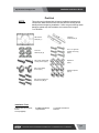
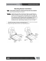
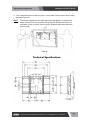
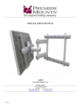
Installation and User’s Guide
Installation and User’s Guide
BIG SCREEN FLAT LCD DISPLAY MOUNT MODEL
WB-72 WALL MOUNT BRACKET
http://www.orionimages.com
All contents of this document may change without prior notice, and actual product appearance may differ
from that depicted herein
http://www.orionimages.com
Installation and User’s Guide
TABLE OF CONTENTS
Warning Statements ............................................................................................................
Parts List .............................................................................................................................
Installation Tools ..................................................................................................................
Mounting Bracket Installation ...............................................................................................
WB-72 Installation ................................................................................................................
Installing the Flat Panel Display (WB-72) ..............................................................................
Technical Specifications ......................................................................................................
Warranty ................................................................................................................................
Contact ................................................................................................................................
2
7300 Bolsa Avenue, Westminster CA 92683 / Tel: 714-766-6300 / Fax: 714-766-6310
3
4
4
5
8
10
11
12
12
pg2
Installation and User’s Guide
http://www.orionimages.com
Warning Statements
WARNING
THE WALL STRUCTURE MUST BE CAPABLE OF SUPPORTING AT LEAST A
MAXIMUM WEIGHT OF 50 LBS. IF NOT, THE WALL MUST BE REINFORCED.
PROPER INSTALLATION PROCEDURE BYAQUALIFIED SERVICE TECHNICIAN,
AS OUTLINED IN THE INSTALLATION INSTRUCTIONS, MUST BE ADHERED
TO. FAILURE TO DO SO COULD RESULT IN SERIOUS PERSONAL INJURY, OR
EVEN DEATH.
WARNING
SAFETY MEASURES MUST BE PRACTICED AT ALL TIMES DURING THE
INSTALLATION OF THIS PRODUCT. USE PROPER SAFETY GEAR AND TOOLS
FOR THE INSTALLATION PROCEDURE TO PREVENT PERSONAL INJURY.
WARNING
PRIOR TO THE INSTALLATION OF THIS PRODUCT, THE INSTALLATION
INSTRUCTIONS SHOULD BE READ AND COMPLETELY UNDERSTOOD. THE
INSTALLATION INSTRUCTIONS MUST BE READ TO PREVENT PERSONAL
INJURY AND PROPERTY DAMAGE. KEEP THESE INSTALLATION
INSTRUCTIONS IN AN EASILY ACCESSIBLE LOCATION FOR FUTURE
REFERENCE.
Indicates that the power plug is to be disconnected from the power outlet.
Safety precautions must be taken at all times.
Warning and Caution statements.
A secure structure must support the weight, or load, of the display. When mounting
to a wall that contains wooden studs, dead center of the wooden stud must be
confirmed prior to installation.
Do not install on a structure that is prone to vibration, movement or chance of
impact. Failure to do so could result in damage to the display and/or damage to the
mounting surface.
Do not install near heater, fireplace, direct sunlight, air conditioning or any other
source of direct heat energy. Failure to do so may result in damage to the display
and could increase the risk of fire.
At least two qualified people should perform the installation procedure. Injury and/or
damage can result from dropping or mishandling the display.
Recommended mounting surfaces: wooden studs and solid-flat concrete. If the
mount is to be installed on any surface other than wooden studs, use suitable
hardware (which is commercially available).
Contact Orion Images with any technical/ installation questions.
3
7300 Bolsa Avenue, Westminster CA 92683 / Tel: 714-766-6300 / Fax: 714-766-6310
pg3
Installation and User’s Guide
http://www.orionimages.com
Part List
NOTE:
This wall mount is shipped with all proper installation hardware and
components. Make sure that none of these parts are missing and/or
damaged before beginning installation. If there are parts missing and/or
damaged, please stop the installation and contact Orion Images.
714-766-6300
WB-72 Wall
Plate (Qty 1)
Mounting
Brackets (Qty 2)
5/16” Flat
Washers (Qty 6)
5/16” x 3” Lag Bolts
(wooden studs only)
(Qty 6)
M6 x 30mm Lateral Shift
Locking Screws (Qty 2)
Griplates™
(Qty 6)
M6 x 12mm Safety
Knobs (Qty 2)
M8 Nylon Spacers
(Qty 6)
M8 x 25mm Phillips Pan
Head Screws (Qty 6)
Installation Tools
Phillips Head Screw Driver,
Pencil
Level (Supplied)
4
Soft Material/ Blanket,
Tape Measure,
1/2” Socket and Wrench
Drill Gun,
7300 Bolsa Avenue, Westminster CA 92683 / Tel: 714-766-6300 / Fax: 714-766-6310
pg4
http://www.orionimages.com
Installation and User’s Guide
Mounting Bracket Installation
NOTE: Proper installation procedure by qualified personnel as outlined in the installation
instructions must be adhered to. Failure to do so could result in serious personal
injury and possible damage to the flat panel.
WARNING: INVERT THE FLAT PANEL. PLACE IT ON A SOFT, FLAT SUFRACE TO
PREVENT DAMAGE TO THE FLAT PANEL. USE A BLANKET, FOAM, ETC.
FAILURE TO DO SO WILL RESULT IN DAMAGING THE FLAT PANEL. DO
NOT LAYTHE FLAT PANELON THE FLOOR WITHOUT ANY PROTECTION
TO THE GLASS. THE FLAT PANEL IS HEAVY AND FRAGILE. AT LEAST (2)
QUALIFIED PERSONNEL ARE STRONGLY RECOMMENDED FOR
INSTALLATION OF THIS PRODUCT. FAILURE TO DO SO COULD RESULT
IN SERIOUS INJURY AND POSSIBLE DAMAGE TO THE FLAT PANEL.
1.
Once the flat panel is inverted, use a measuring tape to find the center of your flat panel
measuring from outside to outside of the chassis (Figure 4).
2. Using a pencil lightly mark the center of your flat panel (Figure 5).
5
7300 Bolsa Avenue, Westminster CA 92683 / Tel: 714-766-6300 / Fax: 714-766-6310
pg5
http://www.orionimages.com
Installation and User’s Guide
3. Determine where the mounting points are (Figure 6).
4. Lay the mounting brackets (stamped arrows facing out) over the mounting points (Figure 7).
5. Match the center of viewing guide with the centerline you marked in Step 1 (Figure 8).
6. The mounting brackets are designed with a center of viewing guide on the outside (Figure 9).
6
7300 Bolsa Avenue, Westminster CA 92683 / Tel: 714-766-6300 / Fax: 714-766-6310
pg6
http://www.orionimages.com
Installation and User’s Guide
7. The Griplates™ have M4, M5 M6 and M8 hole patterns to fit the hardware that your flat
panel requires.
EXAMPLE: If your plasma uses M8 x 20 Phillip screws. Use the M8 mounting points (Figure 10)..
8. Once the mounting brackets are aligned secure the Griplate™ to the flat panel. Use (1)
Griplate™ per mounting point (Figure 11).
NOTE:
7
The dimples of the top plates have to be facing up and the bottom dimples must be
facing down.
7300 Bolsa Avenue, Westminster CA 92683 / Tel: 714-766-6300 / Fax: 714-766-6310
pg7
Installation and User’s Guide
http://www.orionimages.com
WB-72 Installation
1. Using a (commercially available) wood stud finder, locate the 16" or 24" stud centers behind
the wall (Figure 12).
2. Once found, make a pencil marking on the center of the wood studs (Figure 13)
NOTE: The wall plates have 16" and 24" mounting slot positions.
3. Place the wall plate to the reference line and mark the six (6) lag bolt mounting points through
the wall plate slots on the wall..
Stud Finder
Mark the Wall and
the Center of the
Wood Studs
Wood Stud
behind the Wall
Measure and
Mark the
Desired
Viewing
Height
8
7300 Bolsa Avenue, Westminster CA 92683 / Tel: 714-766-6300 / Fax: 714-766-6310
pg8
Installation and User’s Guide
http://www.orionimages.com
4. Level the wall plate with the reference arrow pointing up to the ceiling (Figure 15).
5. Drill six (6) ¼" pilot holes to the marked wall.
6. Secure the plate using the six (6) 5/16" lag bolts and flat washers (Figure 16).
Mark the Six Mounting
Slot Openings
Wall Plate
Wall Plate
5/16” x 3”
Lag Bolts
9
7300 Bolsa Avenue, Westminster CA 92683 / Tel: 714-766-6300 / Fax: 714-766-6310
pg9
http://www.orionimages.com
Installation and User’s Guide
Installing the Flat Panel Display (WB-72)
WARNING:
AT LEAST (2) QUALIFIED PERSONNEL ARE STRONGLY RECOMMENDED
FOR INSTALLATION OF THIS PRODUCT. FAILURE TO DO SO COULD
RESULT IN SERIOUS INJURY AND POSSIBLE DAMAGE TO THE FLAT
PANEL.
1. Raise the flat panel with the mounting brackets secured to the flat panel and insert the top
hooks over the upper rod. The lower hooks should rest on the lower rod (Figure 16).
2. Make any lateral shift adjustment and lock it by tightening the two (2) M6 x 30mm Phillips
screws found on the bottom of the mounting brackets. Use the foot leveler to adjust your
plasma.
CAUTION: Do not over tighten the M6 x 30mm screws to the rods (Figure 17).
NOTE:
To remove the display from the wall simply back off the M6 x 30mm screws using
a Phillips screwdriver and lift the unit of the wall carefully.
10
7300 Bolsa Avenue, Westminster CA 92683 / Tel: 714-766-6300 / Fax: 714-766-6310
pg10
http://www.orionimages.com
Installation and User’s Guide
3. Tilt the flat panel and secure the two (2) M6 x 12mm safety knobs to each of the mounting
brackets (Figure 18).
NOTE:
To remove the display from the wall simply extend the display to its maximum tilt
range, remove the two 6 (mm) safety knurl knobs push the flat panel back to it’s
flat position, loosen or remove the two (2) M6 x 30 lateral shift screws and lift the
unit of the wall.
Technical Specifications
11
7300 Bolsa Avenue, Westminster CA 92683 / Tel: 714-766-6300 / Fax: 714-766-6310
pg11
http://www.orionimages.com
Installation and User’s Guide
Limited Lifetime Warranty
All Orion Images products carry a limited lifetime warranty from ship date against defects in
materials and workmanship. Orion Images is not liable for improper installation that results in
damage to mounts, adapters, display equipment or personal injury.
Contact Orion Images
In the event of missing and/or damage equipment, or technical questions, the
following information can help in the completion of the installation.
Address: 7300 Bolsa Avenue, Westminster, CA 92683
Tel: 714-766-6300 / Fax: 714-766-6310
Email: [email protected]
Website: http://www.orionimages.com
12
7300 Bolsa Avenue, Westminster CA 92683 / Tel: 714-766-6300 / Fax: 714-766-6310
pg12