1
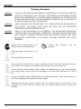
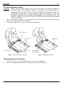
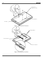
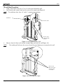
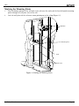
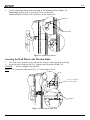
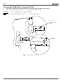
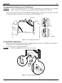
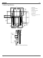
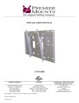
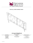
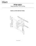
INSTALLATION MANUAL
SFM1
Sony Electronics, Inc.
16540 West Bernardo Drive
San Diego, CA 92127
www.sony.com
PBL-110 Projector Mount
Page 2
Installation Manual
SFM1
Table Of Contents
Warning Statements .................................................................................................................................................... 4
Parts List ....................................................................................................................................................................... 5
Flat Panel List ............................................................................................................................................................... 5
Installation Tools ......................................................................................................................................................... 5
Flat Panel Mount Location ......................................................................................................................................... 6
Mounting Bracket Positioning .................................................................................................................................... 6
Griplates™ ..................................................................................................................................................................... 9
Wood Stud Location .................................................................................................................................................. 10
Marking The Mounting Points ................................................................................................................................. 11
Securing The Wall Plate To The Wooden Studs ..................................................................................................... 12
Securing The Wall Plate To A Concrete Wall .......................................................................................................... 13
Securing The Flat Panel To The Wall Mount .......................................................................................................... 14
Lateral Shift Adjustment ........................................................................................................................................... 14
Security Cable ............................................................................................................................................................. 15
Technical Specifications ............................................................................................................................................ 16
Warranty ..................................................................................................................................................................... 17
Customer Support ...................................................................................................................................................... 17
Notes ........................................................................................................................................................................... 18
Installation Manual
Page 3
SFM1
Warning Statements
WARNING:
THE WALL STRUCTURE MUST BE CAPABLE OF SUPPORTING AT LEAST FIVE (5) TIMES THE
WEIGHT OF THE DISPLAY. IF NOT, THE WALL STRUCTURE MUST BE REINFORCED. PROPER
INSTALLATION PROCEDURE BY A QUALIFIED SERVICE TECHNICIAN, AS OUTLINED IN THE
INSTALLATION INSTRUCTIONS, MUST BE ADHERED TO. FAILURE TO DO SO COULD RESULT
IN SERIOUS PERSONAL INJURY, OR EVEN DEATH.
WARNING:
SAFETY MEASURES MUST BE PRACTICED AT ALL TIMES DURING THE INSTALLATION OF
THIS PRODUCT. USE PROPER SAFETY GEAR AND TOOLS FOR THE INSTALLATION
PROCEDURE TO PREVENT PERSONAL INJURY.
WARNING:
PRIOR TO THE INSTALLATION OF THIS PRODUCT, THE INSTALLATION INSTRUCTIONS
SHOULD BE READ AND COMPLETELY UNDERSTOOD. THE INSTALLATION INSTRUCTIONS
MUST BE READ TO PREVENT PERSONAL INJURY AND PROPERTY DAMAGE. KEEP THESE
INSTALLATION INSTRUCTIONS IN AN EASILY ACCESSIBLE LOCATION FOR FUTURE
REFERENCE.
Indicates that the power plug is to be
disconnected from the power outlet.
Contact Sony
questions.
Electronics
with
any
Safety precautions must be taken at all
times.
Warning and Caution statements.
Do not install on a structure that is prone to vibration, movement or chance of impact. Failure to
do so could result in damage to the display and/or damage to the mounting surface.
Do not install near heater, fireplace, direct sunlight, air conditioning or any other source of direct
heat energy. Failure to do so may result in damage to the display and could increase the risk of
fire.
At least two qualified people should perform the installation procedure. Injury and/or damage can
result from dropping or mishandling the plasma display.
Recommended mounting surfaces: wooden studs and solid-flat concrete. If the mount is to be
installed on any surface other than wooden studs, use suitable hardware (which is commercially
available).
Page 4
Installation Manual
SFM1
Parts List
NOTE:
This wall mount is shipped with all proper installation hardware and components. Make sure that
none of these parts are missing and/or damaged before beginning installation. If there are parts
missing and/or damaged, please stop the installation and contact Sony Electronics (800)222-7669.
Wall Plate (1ea)
Mounting
Brackets (Left and
Right)
Griplates™
(4ea)
5/16” x 3” Lag
Bolts (4ea)
(Wooden studs
only)
M6 x 12mm
(4ea)
5/16” Flat
Washers-Metal
(8ea)
Flat Panel List
SONY
Fits All Sony Professional plasma and Large LCD Panels.
Installation Tools
Phillips Head Screw Driver
Soft Material/ Blanket
Installation Manual
Portable Drill
Pencil
¼” Drill Bit
Tape Measure
Level
Wrench with ½” Drive Socket
Page 5
SFM1
Flat Panel Mount Location
WARNING:
1.
2.
INVERT THE FLAT PANEL PLACE IT ON A SOFT, FLAT SUFRACE TO PREVENT DAMAGE TO
THE FLAT PANEL. USE A BLANKET, FOAM, ETC. FAILURE TO DO SO WILL RESULT IN
DAMAGING THE FLAT PANEL. DO NOT LAY THE FLAT PANEL ON THE FLOOR WITHOUT ANY
PROTECTION TO THE GLASS. THE FLAT PANEL IS HEAVY AND FRAGILE. AT LEAST (2)
QUALIFIED PERSONNEL ARE STRONGLY RECOMMENDED FOR INSTALLATION OF THIS
PRODUCT. FAILURE TO DO SO COULD RESULT IN SERIOUS INJURY AND POSSIBLE DAMAGE
TO THE FLAT PANEL.
Once the flat panel is inverted, use a measuring tape to find the center of your flat panel measuring
from outside to outside of the chassis (Figure 1).
Using a pencil lightly mark the center of your flat panel (Figure 2).
Top of Flat Panel
Inverted Flat
Panel
Inverted Flat
Panel
Measuring Tape
CL
Bottom of Flat
Panel
Figure 1. Flat Panel Mount Location
CL
Mark the Center
of the Flat Panel
Figure 2. Marking the Mount
Mounting Bracket Positioning
1.
2.
Install the nylon spacers to the mounting points on the flat panel (Figure 3)
Lay the left and right mounting brackets (stamped arrows facing out) (Figure 4).
Page 6
Installation Manual
SFM1
Nylon Spacers, If
Applicable (See Chart)
Inverted Flat Panel
Center Mark
Figure 3. Mounting Bracket Positioning
Mounting Brackets
Arrows Facing OUT
Bottom of Flat Panel
Figure 4. Mounting Bracket Installation
Installation Manual
Page 7
SFM1
NOTE:
The mounting guides are designed with a center viewing guide on the side of them. There will be
a “notch” cut on the side of the bracket (Figure 5).
Mounting Bracket
Bottom of Flat
Panel
Center of Flat
Panel
Center of Viewing
Guide
Figure 5. Locating the Center of the Flat Panel
3.
Match the center of the viewing guide with the centerline you marked in Step 1 (Figure 6).
CL
Bottom of the Flat
Panel
Align the Mounting
Brackets
Figure 6. Adjusting the Mounting Brackets
Page 8
Installation Manual
SFM1
Griplates™
1.
The Griplates™ have M4, M5, M6 and M8 hole patterns to fit the hardware that the flat panel requires.
Examples: If your display uses M8 x 20 Phillips head screws. Use the M8 mounting points (Figure 7).
Dimples
M8
M6
M5
M4
Figure 7. Griplates™ Orientation
2. Once the mounting brackets are aligned, secure the Griplate™ to the flat panel.
NOTE:
The dimples of the top plates have to be facing up and the bottom dimples must be facing down.
Use (1) Griplate™ per mounting point (Figure 8).
Leave a ¾” gap on both mounting brackets as shown on this diagram.
NOTE:
CAUTION:
Do not over tighten the mounting hardware.
Phillips Screw Driver
DIMPLES
FACING UP
DIMPLES
FACING UP
DIMPLES
FACING DOWN
Bottom Flat Panel
DIMPLES
FACING DOWN
3/4"
Figure 8. Griplate™ Attachment
Installation Manual
Page 9
SFM1
Wood Stud Location
1. Using a stud finder, locate the 16” or 24” stud centers behind the wall.
2. Once found, make a pencil mark on the center of the wood studs (Figure 9).
NOTE: The wall plates have three 16” and 12” mounting slot positions.
Stud Finder
Wooden Studs
16"
Wooden Studs
behind the Wall
Structure
Figure 9. Locating the Wooden Stud
3. Measure from the floor to the desired viewing height and mark the wall (Figure 10).
NOTE:
This marking will reference the center of your flat panel display once mounted to the wall.
16"
Measure and
Mark the Desired
Viewing Height
on the Wall
Figure 130. Measuring the Height
Page 10
Installation Manual
SFM1
Marking the Mounting Points
1.
2.
Place the bottom portion of the wall plate to the reference line and mark the four (4) lag bolt mounting
points through the wall plate slots on the wall.
Level the wall plate with the reference arrow pointing up to the ceiling (Figure 11).
Wall Plate
16"
Mounting Slots
Level
Wood Studs
Figure 11. Marking the Mounting Points
Installation Manual
Page 11
SFM1
3.
Use the information below when mounting to the following surfaces (Figure 12):
Wood Studs: Drill four (4) ¼” pilot holes to the marked wall.
Concrete Wall: Drill four (4) 3/8” pilot holes to the marked wall
Drill Gun
Pilot Holes
16"
Figure 12. Mounting Surfaces
Securing the Wall Plate to the Wooden Studs
1. Level and secure the plate to the wall with the reference arrow facing up to ceiling.
2. Secure the plate using four (4) 5/16” lag bolts and flat washers (Figure 13).
CAUTION:
Do not overtighten the lag bolts.
NOTE: Use a minimum diameter of 5/16” x 3” long wooden screws.
Level
5/16” x 3” (4ea) and
flat washers (4ea)
Wall Plate
Figure 13. Securing the Wall Plate
Page 12
Installation Manual
SFM1
Securing the Wall Plate to a Concrete Wall
1. Level and secure the plate to the wall with the reference arrow facing up to the ceiling.
2. Use a minimum diameter of 5/16” x 2 ¼” wedge anchors (Figure 14).
CAUTION:
Do not overtighten the wedge anchor bolts.
NOTE: Use a minimum diameter of 5/16” x 2 ¼”” long wedge anchors.
5/16” x 2 ¼”
Wedge Anchors
(4ea)
Wall Plate
Figure 14. Concrete Installation
nstallation Manual
Page 13
SFM1
Securing the Flat Panel to the Wall Mount
WARNING:
1.
At least (2) qualified personnel are strongly recommended for installation of this product.
Failure to do so could result in serious injury and possible damage to the flat panel.
Raise the flat panel with the LEFT and RIGHT mounting brackets secured to the flat panel and insert
the top hooks from each bracket to the rod on the wall plate (Figure 15).
Wall Plate
TOP
BOTTOM
Figure 15. Securing the Flat Panel
Lateral Shift Adjustment
1.
Make any lateral shift adjustment and lock it by tightening the two (2) ¼”-20 Phillips screws found on
the bottom of the mounting brackets (Figure 16).
2. Use the foot leveler to adjust your plasma.
CAUTION:
Do not over tighten the ¼”-20 screws to the rods.
Lateral Shift
Figure 16. Lateral Shift Adjustment
Page 14
Installation Manual
SFM1
Security Cable
1
2
3
4
Installation Manual
Page 15
SFM1
Technical Specifications
28.000
(171.2)
16.000
(406.4)
1.245
(31.75)
A.
B.
C.
D.
E.
F.
G.
H.
A
CL
B
5.000 3.500
(127) (88.9)
Wall plate
Mounting brackets
Griplate™
Mounting hardware
Safety screws
Leveling feet
Wood stud
5/16” x 3” Lag screws and
flat washers
21.790
(553.4)
CL
H
C
16.000
(406.4)
16.000
16.000 (406.4)
(406.4)
24.290
(616.97)
G
E
D
F
1.943
(49.3)
B
H
A
5.000
(127)
21.790
(553.4)
F
Figure 17. Technical Specifications
Page 16
Installation Manual
SFM1
Warranty
Limited Lifetime Warranty
This product carries a limited lifetime warranty from ship date against defects in materials and workmanship.
Sony Electronics is not liable for improper installation that results in damage to mounts, adapters, display
equipment or personal injury.
Customer Support
In the event of missing and/or damage equipment, or technical questions, the following information can help
in the completion of the installation.
Customer Service 877-350-3477
Installation Manual
Page 17
SFM1
Notes
Sony Electronics, Inc.
16540 West Bernardo Drive
San Diego, CA 92127
(800) 222-7669
www.sony.com
©Sony 2005
Page 18
Installation Manual