1
TR114 PCI Digital
Hardware Guide
Document Number 930-412-72
Printed January 1999
410 First Avenue
Needham, MA 02494-2772
781-449-4100
www.brooktrout.com
Copyright© 1998-1999 Brooktrout Technology, Inc. All rights reserved.
This manual is copyrighted and all rights are reserved by Brooktrout Technology,
Inc. This product may not, in whole or in part, be copied, photocopied,
reproduced, translated, or reduced to any electronic medium or machine readable
form without prior consent, in writing, from Brooktrout Technology, Inc.
Information contained in this document is subject to change without notice.
Printed in the United States of America.
Trademarks
Brooktrout Technology™, TR Series™, TR114™, TRNIC™, and Universal
Port™ are trademarks of Brooktrout Technology, Inc.
MS-DOS®, Windows®, Windows NT®, and Visual C++® are registered
trademarks of Microsoft Corporation.
Sun™, Solaris™, SPARC™, and SunSoft™ are trademarks of Sun
Microsystems, Inc.
Intel® is a registered trademark of Intel Corporation.
MVIP™ is a trademark of Natural MicroSystems Corporation.
PEB™ and SCbus™ are trademarks of Dialogic Corporation.
Other company or product names mentioned herein may be trademarks or
registered trademarks of their respective companies.
Technical Assistance
See Chapter 5, Service Information.
LIMITED WARRANTY
Brooktrout Technology, Inc. ("Brooktrout") warrants the hardware component of
the product described in this documentation (the "Product") to be free from
defects in materials and workmanship under normal and proper use for a period
of one year from the date of purchase from Brooktrout. This warranty applies to
the tangible media on which software and firmware are recorded, but does not
apply to the software and firmware themselves. This warranty also does not
apply to any expendable components, any damage resulting from abuse of the
Product, or normal wear and tear. In the event of a warranty claim, the defective
item will be repaired or replaced, at Brooktrout's option, upon delivery to
Brooktrout of the defective item. Brooktrout is not responsible for transportation
and related charges in connection with shipment of items to Brooktrout for
warranty service. Brooktrout reserves the right to charge for inspection of
returned items if it is determined that the items were not defective.
With respect to software and firmware, it should be understood that these
components are complex works which may contain undiscovered defects.
Although the software and firmware provided with the Product contain
substantially the features described in the documentation, to the extent applicable
to the product purchased, no assurance can be given that operation of such
software and firmware will meet the user's requirements or be uninterrupted or
free of errors.
Except as expressly agreed by Brooktrout in writing, Brooktrout makes no
representations or warranties of any kind, express or implied, with respect
to the Product or any hardware, software or firmware components thereof.
In particular, but without limitation of the foregoing, Brooktrout disclaims
all implied warranties of merchantability or fitness for a particular purpose.
Some states do not allow the exclusion of implied warranties so the above
exclusion may not apply to you.
In no event shall Brooktrout be liable for loss of profits or indirect, special,
incidental, or consequential damages relating to the Product. Brooktrout's total
liability, in contract, tort or otherwise, in any way connected with the Product
shall be the correction, repair or replacement of any defective item or, at
Brooktrout's option, the payment of actual direct damages not to exceed the
payments made to Brooktrout for the Product in question. Some states do not
allow the limitation or exclusion of liability for incidental or consequential
damages, so the above limitation and exclusion may not apply to you.
This warranty gives you specific legal rights. You may also have other rights
which vary from state to state.
Contents
Preface
About this Manual . . . . . . . . . . . . . . . . . . . . ix
Related Documents . . . . . . . . . . . . . . . . . . . x
Manual Conventions . . . . . . . . . . . . . . . . . . x
Chapter 1 Introduction
Configurations . . . . . . . . . . . . . . . .
Features . . . . . . . . . . . . . . . . . . .
Computer Platforms . . . . . . . . . . . . .
Hardware Requirements . . . . . . . . . .
Operating and Environmental Requirements
.
.
.
.
.
.
.
.
.
.
.
.
.
.
.
.
.
.
.
.
.
.
.
.
.
1-1
1-1
1-2
1-3
1-3
Board Layout . . . . . . . . . . . . . . . . . .
Default Configuration Settings . . . . . . . . .
Changing the Default Settings . . . . . . . . .
Setting MVIP Clock Termination . . . . . .
Setting T1 Options on the TR114+P8V-T1 .
Setting the T1 Cable Length . . . . . . . .
Setting MVIP Options on the TR114+P8V-T1
Setting the Board ID (SCBus Boards Only) .
Setting Termination for the SCbus . . . . .
Installing the TR114 Board . . . . . . . . . . .
Attaching the PCM Bus to the TR114 . . . .
MVIP Cabling Specifications . . . . . .
SCbus Cabling Specifications . . . . . .
After Installing the Board and Cables . . . .
.
.
.
.
.
.
.
.
.
.
.
.
.
.
.
.
.
.
.
.
.
.
.
.
.
.
.
.
. 2-1
. 2-2
. 2-3
. 2-4
. 2-5
. 2-6
. 2-7
. 2-8
2-10
2-11
2-11
2-12
2-12
2-14
Chapter 2 Configuration and Installation
v
Installing Software . . . . . . . . . . . . . . .
Installing the Brooktrout Software . . . . . .
Installing LAN Fax Software . . . . . . . . .
Using PCI and ISA Boards in the Same System
.
.
.
.
.
.
.
.
2-14
2-14
2-14
2-15
Chapter 3 Connecting to the Telephone Service
T1 and E1 Telephone Service . . . . . . . . . . .
Connecting the P8V-T1 to the T1 Telephone Service
Using a Channel Service Unit . . . . . . . . . .
Configuration of the T1 Network Connection . . . .
Pinouts for the T1 Connector . . . . . . . . . .
T1 Cables . . . . . . . . . . . . . . . . . . . .
Twisted Cable . . . . . . . . . . . . . . . .
Crossover Cable . . . . . . . . . . . . . .
Straight-Through Cable . . . . . . . . . . .
. 3-1
3-1
. 3-2
. 3-3
. 3-3
. 3-4
. 3-4
. 3-5
. 3-5
Chapter 4 Testing and Troubleshooting
Testing the Board . . . . . . . . . . . .
Installing the Test Software . . . . .
Changing the Configuration File . .
Testing the Configuration Settings .
Identifying Channels . . . . . . . .
Testing Channels . . . . . . . . . .
Before You Test Channels . . .
The faxtest Command . . . . . . . .
Sending a Fax . . . . . . . . . . . .
Receiving a Fax . . . . . . . . . . .
Redirecting the Test Results to a File
Creating a Message Log . . . .
Rebooting the System . . . . . . . .
Replacing Your Test Software . . .
Troubleshooting . . . . . . . . . . . . .
TR114+P8V-T1 Error Conditions . .
The Loopback Switch . . . . . .
btdriver Conditions . . . . . . . . .
faxtest Conditions . . . . . . . . . .
vi TR114 PCI Digital Hardware Guide
.
.
.
.
.
.
.
.
.
.
.
.
.
.
.
.
.
.
.
.
.
.
.
.
.
.
.
.
.
.
.
.
.
.
.
.
.
.
.
.
.
.
.
.
.
.
.
.
.
.
.
.
.
.
.
.
.
.
.
.
.
.
.
.
.
.
.
.
.
.
.
.
.
.
.
.
.
.
.
.
.
.
.
.
.
.
.
.
.
.
.
.
.
.
.
.
.
.
.
.
.
.
.
.
.
.
.
.
.
.
.
.
.
.
. 4-1
. 4-2
. 4-3
. 4-4
. 4-5
. 4-6
. 4-6
. 4-7
. 4-8
. 4-8
. 4-9
. 4-9
. 4-9
4-10
4-10
4-10
4-10
4-11
4-12
Chapter 5 Service Information
Getting Technical Support . . . . . . . . . . . . . . 5-1
Downloading the Test Software . . . . . . . . . . 5-2
Returning a Defective TR114 Board . . . . . . . 5-2
Appendix A Interpreting LEDs
Channel LEDs . . . . . . . . .
T1 LEDs on the TR114+P8V-T1
T1 Service LEDs . . . . .
T1 Transmission LEDs . .
CSU LEDs . . . . . . .
. .
.
. .
. .
. .
.
.
.
.
.
.
.
.
.
.
.
.
.
.
.
.
.
.
.
.
.
.
.
.
.
.
.
.
.
.
.
.
.
.
.
.
.
.
.
.
.
.
.
.
.
. A-1
. A-1
. A-2
. A-5
. A-5
Appendix B North American Standards Compliance
Telephony Regulations . . . . . . . . . . . . . . . . B-1
FCC Notices for Registered Component Devices . B-1
FCC Rules Regarding Fax Branding . . . . . . . B-2
FCC Regulations For Connecting to a T1 Phone Line
(Part 68) . . . . . . . . . . . . . . . . . . . . B-3
IC Equipment Attachment Limitations (CS-03) . . B-4
Electromagnetic Emissions . . . . . . . . . . . . . . B-5
FCC Emissions Information . . . . . . . . . . . . B-5
IC Emissions Notice . . . . . . . . . . . . . . . . B-6
Safety . . . . . . . . . . . . . . . . . . . . . . . . . B-6
Appendix C Developing Digital Applications
PCM Buses . . . . . . . . . . . . . . . . . . . . .
The digital.cfg File . . . . . . . . . . . . . . . . . .
MVIP Bus Basics . . . . . . . . . . . . . . . . . .
How the API Implements MVIP Operation . . .
SCbus Basics . . . . . . . . . . . . . . . . . . . .
Implementing SCbus Operation . . . . . . . . .
Assigning Time Slots to Resources . . . . .
Setting Up to Operate in PEB Mode . . . .
Setting Up to Operate in SCSA Mode . . . .
How the API Implements SCSA and PEB Modes
Using DNIS on T1 Lines . . . . . . . . . . . . . .
Using Dialing Prefixes to Dial Out . . . . . . . . . .
. C-1
. C-2
. C-4
. C-5
. C-6
. C-8
. C-8
C-10
C-11
C-12
C-12
C-13
vii
Appendix D Using Two or More NICs on the MVIP Bus
Setting MVIP Clock Master (MASTR)
Setting MVIP Clock Synchronization
Setting Stream Selection . . . . . .
MVIP Clock Termination . . . . . .
Index
viii TR114 PCI Digital Hardware Guide
.
.
.
.
.
.
.
.
.
.
.
.
.
.
.
.
.
.
.
.
.
.
.
.
.
.
.
.
.
.
.
.
. D-1
. D-1
. D-2
. D-3
Preface
About this Manual
This manual describes how to configure, install, and test the
Brooktrout PCI digital boards.
This manual is divided as follows:
Chapter 1 - Presents information on the basic features of the TR114
PCI digital boards and describes the hardware, operating, and
environmental requirements of the TR114 PCI digital boards.
Chapter 2 - Explains how to configure and install the TR114 PCI
digital boards and connect the SCbus or MVIP bus to the board.
Chapter 3 - Explains how to connect a TR114+P8V-T1 board to the
telephone service.
Chapter 4 - Describes how to test and troubleshoot TR114 PCI
digital boards as well as the channels that they support.
Chapter 5 - Lists the ways to contact Brooktrout technical support
and describes the information that you should furnish when
requesting help.
Appendix A - Explains how to interpret the LEDs on the TR114
boards.
Appendix B - Provides information on North American regulations
with which the PCI digital boards comply.
Appendix C - Describes the digital.cfg file as well as using DNIS and
dialing prefixes.
Appendix D - Explains how to configure the TR114+P8V-T1 when
there is more than one NIC on an MVIP bus.
ix
Related Documents
TR114 Firmware Installation and Release Notes
Fax, Voice, and Data API V4.0 Volume 1 User’s Guide
Fax, Voice, and Data API V4.0 Volume 2 Programmer’s Reference
TR114 ISA Digital Hardware Guide
If you are a LANfax user, the fax application may come with its own
documentation and not all of the above manuals would be applicable.
Manual Conventions
This manual uses the following conventions:
• Italics denote file names, directory names, and program
names within the general text.
• The Courier font in bold indicates a command sequence
entered by the user at the system prompt, for example:
cd /usr/sys/bfax/app.src
The Courier font not bolded indicates system output, for
example:
c:>Files installed.
• The
icon indicates a Caution because damage to
software or hardware can occur if proper precautions are not
observed.
• When used by itself, the term ‘TR114’ refers to any of the
TR114 PCI digital boards.
x TR114 PCI Digital Hardware Guide
Chapter 1
Introduction
The TR114 PCI digital boards are for use in computers with
PCI buses. The TR114 is suitable for fax broadcast,
fax-on-demand, fax store and forward, LAN fax servers, email to
fax services, and combined voice and fax applications.
Configurations
The TR114 PCI digital board is available in the following
configurations:
TR114+P2V
TR114+P8S
TR114+P8V
TR114+P8V-T1
TR114+P16S
TR114+P16V
Two channels with an MVIP interface.
Eight channels with an SCbus interface.
Eight channels with an MVIP interface.
Eight channels with an MVIP and an
integrated T1 interface.
Sixteen channels with an SCbus interface.
Sixteen channels with an MVIP interface.
Features
The TR114 PCI digital board has the following features:
• Up to 16 independent fax and voice channels in one PCI
bus slot.
• Each channel has a 25 MHz microprocessor (32-bit
CISC with built-in DSP) and 2MB RAM with parity
checking.
• Full Group 3 fax send and receive functionality on each
channel, with advanced features, such as Error
Correction Mode and MR or MMR compression.
1-1
• Speech record and playback.
Each channel can record and play back ADPCM and µ-law
PCM, permitting developers to build a variety of fax and
voice systems—voice-prompted fax retrieval systems, fax
mail systems with voice annotation capability, integrated
voice/fax mail systems — all using a single TR114.
• Downloadable firmware.
You can easily install updates, even in the field, from a
floppy diskette to add enhanced system functionality without
replacing hardware.
• DTMF (Touch-Tone), SIT, CNG, and CED detection
capability.
• Group 3 and 4 fax compression. Auto conversion of ASCII,
MH, MR, MMR, TIFF, and PCX/DCX files and binary file
transfer.
• Automatic reduction or expansion of the page width on
transmission.
• Adaptive call progress detection capability that works
world-wide.
• Links to the telephone network and other CTI boards via the
SCbus or MVIP bus.
• Integrated T1 interface for the TR114+P8V-T1
• API tools and software drivers to work with many operating
systems. Contact Brooktrout technical support for the latest
information on supported operating systems.
Computer Platforms
Brooktrout recommends the following PC manufacturers:
Diversified Technology, Inc. 800-443-2667
Industrial Computer Source 800-523-2320
Compaq Proliant servers: 1600, 2500, 5500, 7000
www.compaq.com
1-2 TR114 PCI Digital Hardware Guide
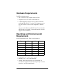
Hardware Requirements
Each TR114 board requires:
• One 32-bit slot in any computer with a PCI bus.
• Telephone service via SCbus or the MVIP bus.
• A digital telephony interface card to connect each board
(except the TR114+P8V-T1) to the T1/E1 telephone service.
The TR114+P8V-T1 has its own integrated T1 interface
card.
You can use the Brooktrout TRNIC Series board (for the
MVIP boards) or any other T1 network interface card that
supports SCbus and MVIP.
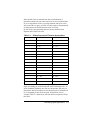
Operating and Environmental
Requirements
Power requirements for the TR114 series boards are:
Type
5V DC
-12V DC
Power
TR114+P2V
750 mA
26 mA
4W
TR114+P8S
1.9 A
104 mA
10.7 W
TR114+P8V
1.26 A
104 mA
7.5 W
TR114+P8V-T1
1.4 A
104 mA
8.3 W
TR114+P16V
4.0 A
208 mA
22.5 W
TR114+P16S
3.8 A
208 mA
21.5 W
• Temperature: 0°C – 50°C (32°F – 122°F)
• Humidity: 10% – 95% (noncondensing)
• Cooling: Direct forced-air flow over each board. We
recommend a supplemental fan blowing directly across the
board for 8- and 16-channel boards.
Introduction 1-3
Chapter 2
Configuration and
Installation
This chapter shows the layout of the boards and explains how to
perform the following operations:
• Set MVIP or PEB termination. The SCbus in SCSA mode
does not require termination.
• Set the T1 options (SW2) and MVIP options (SW3) on the
TR114+P8V-T1 daughter board.
• Set the board ID for SCbus boards (optional).
• Install the TR114 in a system.
• Install the TR114's firmware.
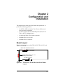
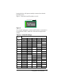
Board Layout
Figure 2-1 shows the layout of the TR114+P2V, TR114+P8V, and
TR114+P16V boards.
MVIP clock termination switches
MVIP Connector
Channel Status LEDs (2, 8, or 16
depending on the board)
PCI Bus Connector
Figure 2-1. TR114+P2V, TR114+P8V, and +P16V Board
Layout
2-1
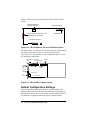
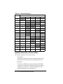
Figure 2-2 shows the layout of the TR114+P8S and TR114+P16S
boards.
Board ID Switches
(on back of board)
SCbus Connector
Channel Status LEDs (8 or 16
depending on the board)
PEB Resistors
PCI Bus Connector
Figure 2-2. TR114+P8S and TR114+P16S Board Layout
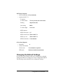
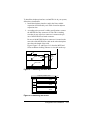
The TR114+P8V-T1 consists of a T1 network interface card mounted
on a TR114+P8V board. Figure 2-3 shows the layout of the
TR114+P8V-T1. The positions of some components on the T1 card
are indicated by dotted lines.
T1 Transmission
LEDs
Channel
Status
LEDs
MVIP clock
termination switches
MVIP Connector
T1 Options
(SW2)
MVIP Options
(SW3)
Loopback
Switch
T1 Service LEDs
T1
Connector
PCI bus connector
Figure 2-3. TR114+P8V-T1 Board Layout
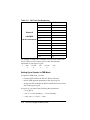
Default Configuration Settings
These PCI boards do not require switch or jumper setting for I/O
address or IRQ because the PC BIOS automatically assigns addresses
and an IRQ to each board. You can quickly set up and install a TR114
PCI board by accepting the following factory-assigned settings:
2-2 TR114 PCI Digital Hardware Guide
MVIP Board Defaults
• MVIP termination: ON (terminated)
• Options for P8V-T1
- T1 options:
T1 clock master
T1 line provides the clock master
Framing
Superframe (SF)
Line coding
B8ZS
T1 cable length
0 to 132 ft.
- MVIP Options:
MVIP stream pair
6/7
MVIP clock master TR114+P8V-T1
MVIP sync ctrl
TR114+P8V-T1
MVIP termination
Unterminated
SCbus Board Defaults
• Board ID
0
• SCbus Termination
SCSA mode
No termination required
PEB mode
Resistors installed (terminated)
Changing the Default Settings
In some cases, you will not be able to use all the factory-assigned
settings and will have to change one or more configuration options.
The following sections describe how to change the settings.
Configuration and Installation
2-3
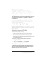
Setting MVIP Clock Termination
The clock on the MVIP bus requires termination. A two position DIP
switch controls termination for the MVIP clock signals on all the
TR114 boards. It is located on the board's top edge, next to the MVIP
connector. See Figures 2-1 and 2-3 for the location of the MVIP
connector on your TR114 board. Set both switches to ON for
termination as shown in Figure 2-4.
M ounting B rac ket
Figure 2-4. MVIP Clock Termination Switches
MVIP clock termination requirements depend on the number of
connections on the MVIP bus. Follow these guidelines:
• Install the telephony network interface card (or the
TR114+P8V-T1) at one end of the cable.
• For systems with 5 or fewer MVIP bus connections,
terminate the MVIP resource board (such as a TR114) at
the end of the cable opposite the NIC. Make all other
boards on the cable unterminated.
• For systems with more than 5 MVIP bus connections,
terminate both ends of the MVIP cable – the NIC and the
MVIP resource board at the opposite end of the cable.
Make all other boards on the cable unterminated.
Switches 5 and 6 of SW3 on the TR114+P8V-T1 daughter board
control termination for the daughter board. See Figure 2-3 for the
location of SW3 and Figure 2-6 for a detailed illustration of SW3.
When setting MVIP clock termination on the TR114+P8V-T1, treat
the base board of the P8V-T1 as a separate board. If you are installing
the TR114+P8V-T1 by itself, terminate just the MVIP clock on the
base board. Otherwise follow the guidelines above.
2-4 TR114 PCI Digital Hardware Guide
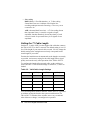
Setting T1 Options on the TR114+P8V-T1
Use the switches of SW2 to set the T1 options. See Figure 2-3 for the
location of SW2 on the TR114+P8V-T1. Switches 7 and 8 of SW2
are nonoperational and do not affect TR114+P8V-T1 operation.
Figure 2-5 shows SW2 with the switches set to the default.
3
4
5
6
7
8
T8
T7
LEN3
LEN2
LEN1
DOWN
B8ZS
2
MASTR
SF
1
Figure 2-5. T1 Switches (SW2)
To configure the T1 clock master, framing mode, and line coding
options for the TR114+P8V-T1, set the switches as shown in
Table 2-1. DOWN means towards the board and UP means away
from the board. Default settings are shown in bold.
Table 2-1. Valid T1 Options
Switch
Meaning
Setting
Mode
1
T1 clock master
(MASTR)
UP
DOWN
Network
TR114+P8V-T1
2
Framing mode
(SF)
UP
DOWN
SF
ESF
3
Line coding
(B8ZS)
UP
DOWN
B8ZS
AMI
The modes are:
• T1 clock master
T1 (network) – T1 generates and transmits the clocking
signals to the TR114+P8V-T1.
TR114+P8V-T1 – The TR114+P8V-T1 generates and
transmits the clocking signals to the T1.
• Framing mode
SF (Super Frame) – A transmission structure that divides
the data into twelve, 193-bit blocks or frames.
ESF (Extended Super Frame) – A transmission structure
that divides the data into twenty-four, 8,000 bps blocks or
frames.
Configuration and Installation
2-5
• Line coding
B8ZS (Binary 8 Zero Substitution) – A T1 line-coding
format that inserts two violations of the bipolar line
encoding technique instead of inserting a 1 for every seven
consecutive 0s.
AMI (Alternate Mark Inversion) – A T1 line coding format
that represents binary 1s (marks) as signals of equal
amplitude, but that alternately inverts the polarity of each
successive mark. It represents binary 0s as signals of zero
amplitude.
Setting the T1 Cable Length
Switches 4, 5, and 6 of SW2 set the length of the cable that connects
the TR114+P8V-T1 to the T1 network. The default setting is 0 to 132
feet. If the length of your network cable exceeds 132 feet, change the
default setting to the setting that most closely corresponds to the
actual length of your cable.
Examine the installation environment and set the length as accurately
as possible. An incorrect setting for the cable length affects signal
quality and can adversely affect operation of the TR114+P8V-T1.
To configure the length of the network cable, set the switches as
shown in Table 2-2. The default settings of switches 4, 5, and 6 are
shaded.
Table 2-2. Valid Cable Length Settings
Cable length
4 (LEN1)
5 (LEN2)
6 (LEN3)
0 to 132 ft.
DOWN
DOWN
DOWN
133 to 266 ft.
UP
DOWN
DOWN
267 to 398 ft.
DOWN
UP
DOWN
399 to 532 ft.
UP
UP
DOWN
533 to 654 ft.
DOWN
DOWN
UP
You can change these switches while the TR114+P8V-T1 is powered
on without causing the board or the system to malfunction. The
TR114+P8V-T1 monitors these switches once every second and
when it detects a change, it reconfigures its operation.
2-6 TR114 PCI Digital Hardware Guide
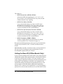
Setting MVIP Options on the TR114+P8V-T1
Use the switches of SW3 to set the MVIP options. See Figure 2-3 for
the location of SW3 on the TR114+P8V-T1. Switches 7 and 8 of
SW3 are nonoperational and do not affect TR114+P8V-T1 operation.
Figure 2-6 shows SW3. In the figure, the switches are set to the
default.
5
6
7
8
TER M2
4
SEC8K
3
TER M1
STR M2
2
M ASTR
STR M1
1
DOW N
Figure 2-6. MVIP Options Switches (SW3)
To configure the MVIP options, set switches 1 through 6 as shown in
Table 2-3. Note that the default switch setting of the switches and the
modes that they select are in bold.
Note: Down means toward the T1 daughter board and UP
means away from the T1 daughter board.
Table 2-3. Valid MVIP Options set with SW3
Switch
Meaning
Setting
Mode
1, 2
MVIP Stream Select UP, UP
(STRM1, STRM2) DOWN, UP
UP, DOWN
DOWN, DOWN
6/7
4/5
2/3
0/1
3
MVIP Clock master UP
(MASTR)
DOWN
TR114+P8V-T1 master
TR114+P8V-T1 slave
4
Clock sync
functions:
4
Sync source ctrl
w/3 UP (SEC8K)
Functioning depends on mode set for MVIP
master clock (switch 3)
UP
DOWN
4
Framing sig. output UP
w/3
(SEC8K)
DOWN
DOWN
5, 6
Termination
(TERM1, TERM2)
TR114+P8V-T1
Secondary net card
Disable output
Enable output
UP, UP
Unterminated
DOWN, DOWN Terminated
Configuration and Installation
2-7
The modes are:
• MVIP Stream Select (STRM1, STRM2)
Selects the MVIP data/signaling pair: 0/1, 2/3, 4/5, or 6/7.
By convention, even numbered streams carry data, and odd
numbered streams carry signaling.
• MVIP Clock Master (MASTR)
Leave at the default setting if you have one NIC on the
MVIP bus. See Appendix D, Using Two or More NICs on
the MVIP Bus for information on setting this switch when
you have more than one NIC on the MVIP bus.
• MVIP Clock Synchronization Functions (SEC8K)
Leave at the default setting if you have one NIC on the
MVIP bus. See Appendix D, Using Two or More NICs on
the MVIP Bus for information on setting this switch when
you have more than one NIC on the MVIP bus.
• MVIP Termination (TERM1, TERM2)
Enables or disables MVIP clock termination. For details,
see Setting MVIP Clock Termination on page 2-4.
Be sure that the MVIP parameters in the digital.cfg file match those
actually used on the TR114+I8V-T1 and its associated resource
boards.
LAN fax users: Typically, for software setup, you set parameters in
the digital.cfg file or through a board setup procedure. See the
documentation supplied with your software.
Setting the Board ID (SCBus Boards Only)
If your system has multiple TR114 PCI boards, it may not be apparent
which board contains which channel numbers. The board ID switches
on the back of the board (see Figure 2-2 for their location) can be
used to uniquely identify the board using a hexadecimal number from
00 through 1F. By identifying each board, you can determine the
channels that belong to that board using the MS-DOS driver or the
faxinit program. See the Brooktrout Application Programming
Interface User’s Guide for more information. Use of the board ID is
optional. You can leave the board ID set to 0 on all TR114 PCI SCbus
2-8 TR114 PCI Digital Hardware Guide
boards; the driver will operate normally no matter what value the
board ID is set to.
Figure 2-7 shows the board ID switches set to 08.
M o u n tin g B ra ck et
1
2
3
4
5
6
O FF
Figure 2-7. Board ID Switches
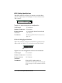
Use switches 2 through 6 to set the board ID. Switch 1 (on the left) is
not operational. Table 2-4 shows the values that correspond to the
settings.
Table 2-4. Board ID Settings
Switch
ID
2
3
4
5
6
00
OFF
OFF
OFF
OFF
OFF
01
OFF
OFF
OFF
OFF
ON
02
OFF
OFF
OFF
ON
OFF
03
OFF
OFF
OFF
ON
ON
04
OFF
OFF
ON
OFF
OFF
05
OFF
OFF
ON
OFF
ON
06
OFF
OFF
ON
ON
OFF
07
OFF
OFF
ON
ON
ON
08
OFF
ON
OFF
OFF
OFF
09
OFF
ON
OFF
OFF
ON
0A
OFF
ON
OFF
ON
OFF
0B
OFF
ON
OFF
ON
ON
0C
OFF
ON
ON
OFF
OFF
0D
OFF
ON
ON
OFF
ON
0E
OFF
ON
ON
ON
OFF
Configuration and Installation
2-9
Table 2-4. Board ID Settings
Switch
ID
2
3
4
5
6
0F
OFF
ON
ON
ON
ON
10
ON
OFF
OFF
OFF
OFF
11
ON
OFF
OFF
OFF
ON
12
ON
OFF
OFF
ON
OFF
13
ON
OFF
OFF
ON
ON
14
ON
OFF
ON
OFF
OFF
15
ON
OFF
ON
OFF
ON
16
ON
OFF
ON
ON
OFF
17
ON
OFF
ON
ON
ON
18
ON
ON
OFF
OFF
OFF
19
ON
ON
OFF
OFF
ON
1A
ON
ON
OFF
ON
OFF
1B
ON
ON
OFF
ON
ON
1C
ON
ON
ON
OFF
OFF
1D
ON
ON
ON
OFF
ON
1E
ON
ON
ON
ON
OFF
1F
ON
ON
ON
ON
ON
Setting Termination for the SCbus
The SCbus can operate in one of two modes:
• SCSA mode
The SCbus in SCSA mode does not require termination. If
the PEB resistor bank is present on the board, remove it.
• PEB mode
The SCbus in PEB mode requires termination. The PEB
termination resistor bank, located directly below the SCbus
connector (see Figure 2-2), controls termination for the
PEB implementation of the SCbus board.
2-10 TR114 PCI Digital Hardware Guide
Install the resistor bank on only the TR114 board attached
to the last connector at the opposite end of the cable from
the network interface card. Remove the resistor bank from
all other TR114 boards in the system.The resistor bank is
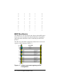
shown in Figure 2-8.
Figure 2-8. PEB Bus Resistor Bank
Installing the TR114 Board
After configuring the board, you are ready to install the TR114 board
in your computer. We recommend you keep a record of the T1 and
MVIP options for the TR114+P8V-T1. You will need these values
later when you configure your software. To install the board:
1. Power off the computer.
2. Remove the computer’s cover. If the system has a board
hold-down bar, remove it as well.
3. Locate an unused PCI slot and remove the bracket for it.
4. Holding the TR114 at each top corner, insert the board
firmly into the PCI slot.
5. Screw the TR114's mounting bracket securely to the
computer's frame.
6. Connect the PCM cable. See Attaching the PCM Bus to the
TR114.
7. Turn on the computer.
Attaching the PCM Bus to the TR114
The MVIP and SCbus protocols adhere to certain cabling
specifications. If you do not follow these cabling specifications when
you cable the resource boards – TR114s, network boards, or other
boards – to the telephony interface card in your system, your system
may fail with a digital configuration error.
The cabling specifications for these protocols, as they are described in
this hardware guide, are described in the following sections.
Configuration and Installation
2-11
MVIP Cabling Specifications
The MVIP connector (see Figure 2-9) attaches to a 40-pin ribbon
cable. See Figures Figure 2-1 and Figure 2-3 for its location on the
TR114 boards.
Pin 1
Figure 2-9. MVIP Connector Pin Configuration
Cable length
22" maximum
Number of connectors
22 maximum
Distance between
connectors
≅1" (at least the distance between board
slots in PCs)
Termination
See Setting MVIP Clock Termination on
page 2-4.
SCbus Cabling Specifications
The SCbus connector (see Figure 2-10) attaches to a twenty-six pin
ribbon cable. See Figure 2-2 for its location on the TR114 boards.
Pin 1
Figure 2-10. Pin Configuration of the SCbus Connector
Cable length
21" maximum
Number of connectors 21 maximum
Distance between
connectors
1.0" minimum
Termination
SCbus in SCSA mode requires no
termination. See Setting Termination for the
SCbus on page 2-10 for termination in PEB
mode.
2-12 TR114 PCI Digital Hardware Guide
To install the telephony interface card and TR114s in your system,
follow these instructions:
1. Install the telephony interface card in the first available
expansion slot followed by each TR114 board in adjacent
expansion slots.
2. According to the protocol’s cabling specifications, connect
the MVIP/SCbus bus connectors to each TR114 making
sure that pin one of the bus connector is connected to pin
one of the MVIP/SCbus board connector.
Pin one of the MVIP/SCbus bus connector is located on the
same side of the MVIP/SCbus cable as the colored strip that
runs down the length of the cable.
Figures Figure 2-11 and Figure 2-12 show the MVIP and
SCbus multiboard cabling schemes as viewed from the top.
MVIP
TR114 +P8V-T1Bus
T1(b)/E1(b)
T1
pin 1
TR114 +P8V side
Metal
bracket
MVIP
Bus
TR114 +P8V
Figure 2-11.Attaching the MVIP Bus
Telephony interface Card
SCbus
TR114
pin
side
TR114
T1
TR114
Figure 2-12.Attaching the SCbus
Configuration and Installation
2-13
After Installing the Board and Cables
Once you have installed the board and cables, you can test the board
by running the faxtest program (see Testing the Board on page 4-1)
and then install software. Or you can install software immediately.
Installing Software
You need to install software to run the boards. If you are an
application developer, you would install the Brooktrout-supplied
driver, API, and firmware. If you use software from another vendor,
see that vendor's manual for instructions on installing software.
Installing the Brooktrout Software
The Brooktrout API and driver are available for a variety of operating
systems. See the Brooktrout Fax, Voice, and Data API User’s Guide
for information on installing the API and driver for a specific
operating system.
The TR114 firmware is included on a single DOS-formatted diskette.
Before running any applications that use the TR114 board, consult the
TR114 Firmware Installation and Release Notes for detailed
instructions on how to copy the contents of this diskette onto your
hard disk. The Brooktrout API/driver downloads the firmware for
you.
Installing LAN Fax Software
If you use software from another vendor, in most cases the firmware
may already be included with the software, which automatically
downloads the firmware to the board.
See your LAN fax application’s user manual for instructions on
installing your LAN fax software. After you have set up your LAN
fax software to support the TR114 board, you can begin sending and
receiving faxes.
2-14 TR114 PCI Digital Hardware Guide
Using PCI and ISA Boards in the Same
System
For PCI boards, the PC BIOS automatically configures the addresses
and hardware interrupts (IRQs), which may change when the system
is rebooted, especially if devices are added or moved.
If you have a TR114 ISA board in your system when you install a
TR114 PCI board, the BIOS will not recognize the ISA board when it
configures the PCI board. All TR114 ISA boards share one unique
IRQ. An IRQ can be shared among PCI boards, but not between PCI
boards and ISA boards. The Brooktrout drivers will not load if such a
conflict exists.
If you select an IRQ when installing the Brooktrout driver, the driver
will reserve that IRQ, but will not use it for the PCI board. If you
select a DMA channel (which is not used by PCI boards), the driver
will reserve that channel, but will not use it for the PCI board. Thus,
you will be wasting the IRQ or DMA channel and could cause a
conflict with another board or device.
If there are conflicts between your TR114 PCI and ISA boards’
resources, you may need to make changes to the computer BIOS or
setup. The method you use depends on your brand of computer.
Check the manufacturer’s instructions for techniques for dealing with
conflicts between boards.
Generally, you can avoid conflicts between PCI and ISA boards by
doing the following:
1. Let the PC BIOS assign the IRQ and I/O addresses to the
TR114 PCI board.
2. Use the tools supplied with the operating system to
determine the interrupts and addresses used by the PCI
board.
3. Configure the interrupts and addresses for the TR114 ISA
boards.
4. If you are installing a TR114 ISA board in an EISA slot,
create an EISA configuration file. Using the BIOS, reserve
the interrupt, I/O addresses, and DMA channel (if used).
The BIOS will not use the resources that are reserved for
ISA (or EISA) boards for your PCI board.
Configuration and Installation
2-15
Chapter 3
Connecting to the Telephone
Service
This chapter provides information on the following topics:
• T1 and E1 telephone service.
• Connecting the P8V-T1 to T1 service.
• Configuration of the T1 connection.
T1 and E1 Telephone Service
T1 telephone service provides digital data transmission at 1.544
Mbps. One T1 robbed-bit line can carry 24 channels of fax, voice, or
other data.
E1 telephone service provides digital data transmission at 2.048
Mbps. One E1 line can carry 30 channels of fax, voice, or other data.
The TR114 board is designed to operate with a T1 or E1 network
interface card. T1 network interface cards with robbed-bit signaling
and T1/E1 network interface cards with ISDN call control are
available from Brooktrout Technology, Inc. In addition, the
TR114+P8V-T1 has an integrated T1 (robbed-bit) interface.
Connecting the P8V-T1 to the T1
Telephone Service
The T1 connector, an RJ-45 telephone jack on the TR114+P8V-T1
mounting bracket, provides the connection to the T1 service. See
Figure A-1. for the location of the T1 connector.
To connect the TR114+P8V-T1 to T1 service, follow these steps:
3-1
1. Insert one end of the T1 cable into the T1 connector in the
TR114+P8V-T1’s RJ-45 telephone jack.
The T1 cable that comes with the TR114+P8V-T1 is a
twisted cable. If you need a straight or crossover cable, you
can order it from Brooktrout Technology or build it
yourself (see Pinouts for the T1 Connector on page 3-3).
2. Insert the other end of the T1 cable into either the T1 wall
jack or the T1 jack on the Channel Service Unit (CSU).
The TR114+P8V-T1 is now connected to T1 telephone service.
Using a Channel Service Unit
The distance between the originating T1 circuit (ask your telephone
representative for this information) and its termination point (the T1
connector on the TR114+P8V-T1) determines whether you must
connect the T1 connector to a CSU (Channel Service Unit) or directly
to a T1 wall jack.
If the T1 circuit is fewer than 500 feet from the TR114+P8V-T1, you
do not need to connect the T1 connector to a CSU. If the distance
from the TR114+P8V-T1 to the T1 circuit exceeds 500 feet, you must
connect the T1 connector to a CSU and the CSU to the T1 wall jack.
CSUs provide these important features:
• Amplify the T1 signal so both ends of the connection detect
the signal correctly.
• You may need to configure the CSU to boost or attenuate
the signal until both ends can detect the signal correctly.
• Provide constant circuit to the telephone company when a
power down occurs.
Since the T1 line continues to receive signal during a power
down (though the T1 line cannot communicate without the
PC), providing constant current prevents the telephone
company from receiving a T1 line failure alarm.You must
provide battery backup to the CSU.
• Provide access to bantam jacks for diagnostic testing and
problem solving.
3-2 TR114 PCI Digital Hardware Guide
• Provide a loop-back mechanism to the telephone company
to test and ensure that signals on the T1 line to the CSU are
good.
Telephone companies use this feature whenever they install
a new T1 line or to diagnose line problems.
• Provide other performance monitoring features and LED
error warning.
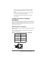
Configuration of the T1 Network
Connection
The T1 connection consists of the connector on the TR114+P8V-T1
and the cable supplied by Brooktrout Technology. You may need this
information if you need a different kind of cable (see below) or you
want to build your own cable.
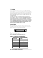
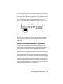
Pinouts for the T1 Connector
Pins 1, 2, 4, and 5 on the RJ-45 provide T1 data paths to and from the
TR114+P8V-T1.
The pins of these connectors are configured as shown in Table 3-1
and as shown in Figure 3-1..
Table 3-1. Pin Configuration of RJ-45 T1 Connector
Tip & Ring
RJ-45 Pin
Transmit Tip
5
Transmit Ring
4
Receive Tip
2
Receive Ring
1
5- Figure 3-1. Pinouts of the RJ-45
Connecting to the Telephone Service
3-3
T1 Cables
At some point between the T1 connector on the TR114+P8V-T1
board and the T1 service connector (CSU, wall-mounted jack, PBX),
one and only one twist must occur in the wiring to connect the receive
tip and ring pins on one connector to the corresponding transmit tip
and ring pins on the opposite connector. All other connections must
be straight through.
To use the correct cable, you need to know the pinout on the T1
service connector side (CSU, wall jack, or PBX). Brooktrout supplies
a 6-foot twisted cable (see Twisted Cable below) but in some cases
you may need to use a crossover cable (see Crossover Cable on page
3-5) or a straight-through cable (see Straight-Through Cable on page
3-5) to connect the transmit tip and ring pins on the TR114+P8V-T1
to the receive tip and ring pins on the T1 circuit.
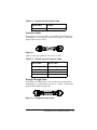
Twisted Cable
The supplied T1 cable (order number: 340-018-02) provides the
connection from the board to the T1 network with the proper twist.
Figure 3-2 shows the design of the twisted cable.
rR
rT
xR
xT
xR
xT
rR
rT
Figure 3-2. Twisted Cable
Table 3-2 shows the pinouts for the twisted cable.
Table 3-2. Pinouts for the Twisted Cable
RJ-45 Pin on one
end of cable
RJ-45 Pin on other end
of cable
1
8
2
7
3
6
4
5
5
4
6
3
7
2
3-4 TR114 PCI Digital Hardware Guide
Table 3-2. Pinouts for the Twisted Cable
RJ-45 Pin on one
end of cable
RJ-45 Pin on other end
of cable
8
1
Crossover Cable
If you require a cross-over cable, you can order it from Brooktrout
Technology Inc. (order number: 340-144-70). Figure 3-3 shows the
design of the crossover cable.
Figure 3-3. Crossover Cable
Table 3-3 shows the pinouts for the crossover cable.
Table 3-3. Pinouts for the Crossover Cable
RJ-45 Pin on one
end of cable
RJ-45 Pin on other
end of cable
5
2
2
5
4
1
1
4
Straight-Through Cable
If you require a straight cable, you can order one from Brooktrout
Technology Inc. (order number: 340-101-07). Figure 3-4 shows the
design of the straight-through cable.
xR
xT
rR
rT
rR
rT
xR
xT
Figure 3-4. Straight-through Cable
Connecting to the Telephone Service
3-5
Table 3-4 shows the pinouts for the straight-through cable.
Table 3-4. Pinouts for the Straight-through Cable
RJ-45 Pin on one
end of cable
RJ-45 Pin on other
end of cable
5
5
4
4
2
2
1
1
3-6 TR114 PCI Digital Hardware Guide
Chapter 4
Testing and
Troubleshooting
Testing the Board
The TR114 PCI board should now be properly configured and
installed in your computer. Appropriate telephone service should be
installed, and the TR114 board should be connected via MVIP to a
TRNIC or TR114+P8V-T1, which is connected to your telephone
service.
Note: You cannot use this test on an SCbus board.
Use the TR114 hardware test program, faxtest.exe, to test the TR114
by sending and receiving faxes.
Users of LAN fax software may test the board using test software
from the LAN fax vendor instead of faxtest.exe. See the manual
shipped with the LAN fax software for more information.
We recommend that you run faxtest on your TR114 board before you
replace the cover on your PC and before you configure your fax
software for the TR114.
The test software includes:
faxtest.exe
A DOS test program used to send and receive
facsimiles.
btdriver.bat, btk1.exe,
btk2.exe
A batch file and DOS program that you must
install before you run the faxtest program.
user.cfg
A configuration file that contains a number
of run-time configuration parameters.
country.cfg
A read-only configuration file with
country-specific information.
test-16.pex,
test-164.pex
Test firmware that the faxtest program
automatically downloads to the TR114.
4-1
send.fil
A single-page Group 3 fax file.
btdriver.cnf
The configuration file that contains the
interrupt, DMA channel, and channel
addresses of the TR114 ISA fax board or
boards that you have installed in your
system. The btdriver batch file uses this
configuration file.
If you installed more than one TR114 or
installed more than one model of TR series
boards, before you run faxtest, you must edit
and change the configuration file as
explained in Changing the Configuration
File on page 4-3.
digital.cfg
A configuration file used by faxtest
containing PCM interface configuration
information that sets general operation
parameters.
To run faxtest, you must:
1. Install the test software.
2. Modify the configuration files, if necessary.
3. Boot up your system under DOS.
4. Check and test the configuration settings.
5. Identify the TR114 channels.
6. Test the channels.
7. Shut down DOS and reboot your operating system.
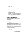
Installing the Test Software
Note: If you are using Windows NT, make sure you do
not use the faxtest program from a DOS window.
Instead, boot from a DOS floppy and run faxtest
from the floppy drive.
To install the test software in a separate directory (for example
\bfax\faxtest) on your hard drive, follow these steps:
4-2 TR114 PCI Digital Hardware Guide
1. Make the \bfax\faxtest directory in which to store the test
software. Type:
mkdir \bfax\faxtest
2. Make the new directory the current directory. Type:
cd \bfax\faxtest
3. Copy the files from the diagnostic diskette into the current
directory. Type:
copy A:*.* *.*
4. Make sure no other software applications or programs for
Brooktrout boards are running.
For MS-DOS, either edit your current autoexec.bat file and
remove the lines that run such software, or create an
alternate autoexec.bat file that does not contain those lines.
5. Reboot your system using the modified or alternate
autoexec.bat file.
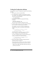
Changing the Configuration File
The configuration file, btdriver.cnf, contains parameters used to
identify the interrupt number, dma channel, and base addresses for
TR114 ISA boards.
If you install only TR114 PCI boards, you must change the contents
of the configuration file to:
intnum -1
dmachan -1
Since you do not have to specify any addresses for the PCI board, you
should delete the line containing the default address (addrs 264 4).
If the system has a TR114 ISA board in addition to PCI boards, you
must specify the appropriate address, IRQ, and DMA channel for the
ISA board, but you should not specify any values for the PCI boards.
For example if you install one TR114 ISA 8-channel board in your
system (at base address 260) along with your PCI board, change the
contents of the configuration file to:
intnum 5
dmachan 1
addrs 264 8
Testing and Troubleshooting
4-3
Testing the Configuration Settings
To test the TR114 board’s configuration settings, use the following
procedure:
1. Boot up your system to run under DOS.
2. Go to the directory to which you copied the test software.
For example, if you copied the test software to the directory
\bfax\faxtest, type the following:
cd \bfax\faxtest
3. Run the btdriver batch file by typing the following
command:
btdriver btdriver.cnf
The batch file should display output on the screen.
4. Check the display output to verify that the program displays
the same number of channels that you installed.
For example, if you have one TR114 8-channel board
installed in your system, you should see the following
output:
Total Channels: 8 TR114; 0 Trufax;
0 TR112/TR111MC; 0 TR200
No BRI TR114s found.
Note that the btdriver batch file checks for all TR114
boards, including the TR114 ISDN (BRI) board.
If you have installed two TR114 8-channel boards in your
system, you should see the following output:
Total Channels: 16 TR114; 0 Trufax;
0 TR112/TR111MC; 0 TR200
No BRI TR114s found.
5. If the correct number of channels is displayed, skip to
Identifying Channels on page 4-5.
If the program fails to find the correct number of channels,
run through the following checklist for possible solutions:
- Make sure the LEDs on the TR114 flash once when you
power up your system.
4-4 TR114 PCI Digital Hardware Guide
If the LEDs fail to flash or if they remain on, a
problem may exist with the TR114 or with the
PC. To determine where the problem lies:
1. Install the TR114 in another slot and power up the
system again.
2. If the LEDs still fail to operate correctly, install
the TR114 in another PC and try again.
3. Check the PC power supply to ensure that it has
adequate power for all the devices in the chassis.
See Operating and Environmental Requirements
on page 1-3 for TR114 power requirements.
4. If the LEDs fail to operate correctly after you have
tried 1, 2, and 3, contact Brooktrout Technical
Support or the reseller from whom you purchased
your TR114 board. To contact Brooktrout
Technical Support, see Service Information on
page 5-1.
- If you are installing one or more TR114 ISA boards in
addition to a TR114 PCI board, then make sure that:
-
each TR114 ISA board has a unique base I/O address
and that it is listed in the btdriver.cnf file.
-
the base I/O address switches and the jumper on the
interrupt header on the ISA board are set correctly to
match the configuration parameter values in the
btdriver.cnf configuration file.
-
the I/O address settings do not conflict with those of
another device in your system.
Identifying Channels
On all TR114 boards, channel numbers start at 0. For example, on
8-channel TR114s, channel numbers are 0, 1, 2, 3, 4, 5, 6, and 7.
However, when you run faxtest with more than one TR114, faxtest
does not look for the assigned channel numbers on the boards after
the first one. Instead, faxtest assumes that channels are numbered
sequentially from board to board, starting with the first channel (0) on
Testing and Troubleshooting
4-5
the TR114 that occupies the lowest base I/O address and ending with
the last channel on the TR114 that occupies the highest base I/O
address. For example, if you want to test the second channel on the
second TR114 8-channel board, enter 9 as the channel number.
If you are using multiple TR114 PCI boards, it may not be apparent
which board corresponds to which addresses and contains which
channel numbers. btdriver provides two features to assist in
identifying boards and channels.
When btdriver is run, it prints information about each TR114 PCI
board detected including the base address, bus number, device
number and function number (the function number is currently
always 0). From the base address you can determine which channels
are on which board. From the bus and device numbers you can
determine the slot in the system in which the board is located. Each
slot in the system has a unique bus and device number that
correspond to it, so by using one board at a time, the correspondence
can be determined for that system.
Also, btdriver has a -f command line option that allows flashing of
LEDs on the board containing a particular channel. After running the
btdriver initially to assign channel numbers, you can then run it again
with the -f option to determine which board contains which channel.
Testing Channels
This section provides instructions for testing channels on the TR114.
There are two tests: one tests the TR114 by sending a fax, the other
tests the TR114 by receiving a fax.
Before You Test Channels
Before testing the TR114, you must perform the following actions:
• Verify that the correct number of channels has been
configured, as described in Testing the Configuration
Settings on page 4-4.
• Connect the TRNIC, the TR114+P8V-T1, or the network
interface card to the T1 service.
• Verify that the TR114+P8V-T1 or the network interface
card is properly connected to the telephone service.
4-6 TR114 PCI Digital Hardware Guide
If connecting to the telephone service via a
TR114+P8V-T1, verify that the T1 line is running by
checking that the green LED is lit.
If connecting to the telephone service via a different
network interface card, verify that the T1 line is running by
performing the appropriate test procedure specified by the
card’s manufacturer.
In addition, you need access to a fax machine to perform these tests.
The faxtest Command
The command used to test channels is faxtest. The faxtest command
has the following syntax:
Send:
faxtest -u # -s wphonenumber send.fil
Receive: faxtest -u # -r
The parameters and arguments are defined as follows:
-u
The unit parameter precedes the number of the
channel to be tested.
#
Specifies the number of the channel to be tested.
Run this test for each channel, typing the
appropriate channel number each time. See
Identifying Channels on page 4-5 for channel
mapping information.
-s
Places the channel in send mode.
-r
Places the channel in receive mode.
Forces the TR114 to wait for wink (E&M wink
protocol) or the availability of a timeslot (E&M
immediate protocol). Used with phonenumber.
w
phonenumber
The phone number of the receiving fax machine.
send.fil
The test file included with the test software.
You should run faxtest on each channel in your system to verify that
the TR114 boards are operating properly. If you need help on the
faxtest program, type:
faxtest
If you need to stop faxtest at any time, press q to quit.
Testing and Troubleshooting
4-7
Sending a Fax
To test a TR114 channel by sending a fax from it, use the following
procedure:
1. Go to the directory to which you copied the test software.
For example, if you copied the test software to the directory
\bfax\faxtest, type the following:
cd \bfax\faxtest
2. Run faxtest specifying the channel to be tested, the -s
argument and the number of the fax machine to receive the
fax. For example, to send the test fax send.fil on channel 0
to 781 555-0000, type the following:
faxtest -u 0 -s w17815550000 send.fil
3. If it completes the fax transmission successfully, the faxtest
program displays the following message:
Fax Sent Successfully - Test Completed.
Otherwise, it displays an error message. See Redirecting the
Test Results to a File on page 4-9.
Receiving a Fax
To receive a fax from a fax machine on any channel, follow these
steps:
1. If you are not already in the correct directory, go to the
directory to which you copied the test software. For
example, if you copied the test software to the directory
\bfax\faxtest, type the following:
cd \bfax\faxtest
2. Run faxtest specifying the channel to be tested and the -r
argument. For example, to test channel 0, type the
following:
faxtest -u 0 -r
3. From a fax machine, dial the telephone number connected
to the channel you are testing, and send it a test fax.
4. If the fax is received successfully, the faxtest program
displays the following message:
Fax Received Successfully - Test Completed.
4-8 TR114 PCI Digital Hardware Guide
Otherwise, it displays an error message. See Redirecting the
Test Results to a File below.
Note: If your T1 is set up as a hunt group for multiple
channels, you may have to coordinate with your
telephone company to receive a fax from a
particular T1 channel.
Redirecting the Test Results to a File
If you still cannot correct the problems you encountered, run the
faxtest program and redirect the output to a file. Brooktrout Technical
Support or the reseller where you bought the TR114 board will want
to examine the diagnostic test results to determine the cause of the
malfunction.
We recommend that you fax or email the test results to Brooktrout
Technical Support or to the reseller. For instructions on how to
contact or send test results to Brooktrout Technical Support, see
Chapter 5, Service Information.
Creating a Message Log
To redirect output to a message log, use one of the command lines
shown below. In the examples, # is the number of the channel you are
testing, and log is the name of the output file. If the program fails to
exit on its own, press q to quit.
To redirect output from faxtest when attempting to send a fax, type:
faxtest -u # -v -s wphonenumber >log
To redirect output from faxtest when attempting to receive a fax, type:
faxtest -u # -v -r >log
Rebooting the System
To configure your fax software and start sending and receiving faxes
with your TR114 board, reboot your system to run under the
operating system you normally use.
If your system normally runs under DOS or Windows 95, and you
booted your system with a special autoexec.bat file to run the test
software, reboot your system now using the original autoexec.bat file
that contains the lines that run your fax application software.
Testing and Troubleshooting
4-9
Replacing Your Test Software
If you do not already have faxtest.exe or if you need to replace your
copy, you can get it from the Brooktrout web site (see Downloading
the Test Software on page 5-2).
Troubleshooting
You may encounter some of the error conditions listed and described
in this section when you run the btdriver and faxtest programs.
To resolve the error condition, find the description of the problem and
follow the instructions given for it. If you still cannot resolve the
problem, see Redirecting the Test Results to a File on page 4-9.
TR114+P8V-T1 Error Conditions
The TR114+P8V-T1 has two sets of LEDs that can be used to
interpret activity on the T1 interface. See Appendix A, Interpreting
LEDs.
The Loopback Switch
The loopback switch is a toggle switch located on the P8V-T1’s
mounting bracket. This switch enables and disables network loopback
mode. D1, the red LED on the left below the loopback switch on the
TR114+P8V-T1, becomes lit when the TR114+P8V-T1 is in network
loopback mode. See Figure A-1 on page A-2 for the location of D1
and the loopback switch.
The telephone company uses network loopback mode to test
individual channels in the T1 span. Turn network loopback mode on –
toggle the loopback switch down – only at the telephone company’s
request.
Make sure loopback mode is off – toggle the loopback switch up –
while the TR114+P8V-T1 is running under normal conditions.
4-10 TR114 PCI Digital Hardware Guide
Solution
no fax or voice
boards found
The system cannot find
any boards. Btdriver
should detect eight
channels for each
eight-channel board.
Put the TR114 in a different slot. Make sure that all the channel
LEDs of the board flash once at power up.
No BRI TR114s
Found
This message is
No action is required.
informational. It means
that you do not have a
TR114 BRI ISDN board
in your system.
Cannot set
BFAX_INFO env
var. X bytes
needed, only
found Y.
Aborting.
The driver required more
temporary environment
space for the
BFAX_INFO variable
than was available.
The environment is limited in space. Different DOS versions use
different amounts of default environment space. Change the
environment space to a larger setting by putting a SHELL directive
in your CONFIG.SYS file. This directive is used to specify a
different command interpreter. The default is \COMMAND.COM.
To change the environment space setting, insert the following line
into CONFIG.SYS for DOS versions earlier than 5.0:
SHELL=C:\COMMAND.COM /P /E:2048
or for DOS 5.0 and later:
SHELL=C:\COMMAND.COM C:\ /P /E:2048
The number 2048 seems to work best in every case. After editing
CONFIG.SYS, reboot and try again.
4-11
Description
Testing and Troubleshooting
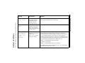
The following messages may be reported by btdriver.
btdriver Conditions
Message
Message
Description
Solution
reset failed
faxtest hangs when
downloading firmware.
1. Check your btdriver.cnf file setting to ensure that the
dma and interrupt are both set to -1.
Originate_call:
Final Call
Progress: Probable
human detected
If the reset still fails, contact Brooktrout Technical
Support (see Getting Technical Support on page 5-1).
A human voice was probably Check the telephone number and have the board dial the
detected instead of a fax
correct fax number.
tone.
Digital
The TR114 is not receiving 1. Replace or check the MVIP cable.
Configuration Error proper clocking signals from 2. Ensure that the MVIP stream selections on the
the TR114+P8V-T1 or NIC
TR114+P8V-T1 or the NIC match the tstream and
due to a malfunctioning
rstream numbers in the digital.cfg file.
MVIP cable or an incorrect
clock setting in the
3. Ensure that the clock_rate parameter is set to 1
digital.cfg file.
(2.048) in the digital.cfg file.
Reorder Busy
On outdialing, the TR114
1. The system is dialing prematurely. Insert a dialing
always reports that the line is
prefix ww or w, at the beginning of each dial string.
busy.
2. Check your PBX to ensure that calls are routed
correctly. You may have to dial 8 or 9 to dial outside.
4-12 TR114 PCI Digital Hardware Guide
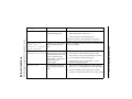
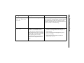
The following messages may be reported by faxtest.
faxtest Conditions
2. Move the board to a different PCI slot.
Message
Description
Solution
4-13
Originate_call:
Dial: No dialtone
detected
The board is not detecting a dialtone.
Check the configuration of your T1 line. You can
insert a second w in the dial string to specify that the
TR114 should wait for dial tone. However, if the
telephone company does not provide a dial tone, do
not put a second w in the dial string.
error 265
The TR114 is not getting a wink or a 1.
timeslot is not available on the T1
line. This error is usually the result of
a misconfiguration in the T1 signaling 2.
protocol, the T1 network board setup,
or the digital.cfg file. It is also
possible that the T1 trunk and the T1 3.
header board configurations do not
match.
Testing and Troubleshooting
Check that the signaling protocol your T1
provider is sending matches the settings in the
digital.cfg file.
Check with the phone company that your T1
service is working.
Ensure that the green LED on the NIC or
TR114+P8V-T1 is on.
Chapter 5
Service Information
In the event of equipment malfunction, Brooktrout Technology, Inc.
or an authorized agent should perform all repairs. The user is
responsible for reporting the need for service to Brooktrout or to one
if its authorized agents.
Getting Technical Support
Brooktrout provides technical support for customers who have
purchased their TR114 product directly from Brooktrout Technology,
Inc. If you purchased your TR114 board from a reseller, please
contact that reseller for technical support.
Before contacting Brooktrout Technical Support, please have the
following information at hand:
• The part number (PN) of the TR114 board. The part
numbers always begins with the digits “802.” On 900 series
boards, the part number is on the back of the TR114 board.
• Test results from running the faxtest program. See Testing
Channels on page 4-6 on how to use the faxtest program.
Contact Brooktrout Technical Support by:
• E-Mail:
US:
[email protected]
Belgium:
[email protected]
Japan:
[email protected]
Singapore:
[email protected]
5-1
• Telephone:
U.S.:
781-433-9600
Monday through Friday
8:30AM – 8:30PM Eastern Time
Europe:
+32-2-658-0170
Singapore:
+65-224-4485
Japan:
+81-3-5800-9102
• FTP Site: ftp://ftp.brooktrout.com
• Web Site: http://www.brooktrout.com
Downloading the Test Software
You can get copies of the latest test software from the Brooktrout web
site. To download the software to your PC:
1. Start your Internet browser.
2. Go to the Brooktrout web site by typing:
http://www.brooktrout.com
3. Select technical support.
4. Select downloads.
5. Select diag.exe.
Returning a Defective TR114 Board
If you suspect that your TR114 board is malfunctioning, contact
Brooktrout Technology, Inc. or the reseller from whom you
purchased the board.
Typically, Brooktrout Technical Support or your reseller will request
you to run the diagnostics on the TR114 board in question to
determine whether or not it has a hardware defect. If it does, you need
to return the board for repair to Brooktrout Technology, Inc. or to the
reseller from whom you purchased it.
5-2 TR114 PCI Digital Hardware Guide
If you purchased the TR114 board directly from Brooktrout
Technology, Inc., Brooktrout will issue a Return Material
Authorization (RMA) number for it. When returning a product on
RMA to Brooktrout Technology, Inc., you must supply the RMA
number clearly on the shipping container and send the container to
the following address:
Brooktrout Technology, Inc.
152 Second Avenue
Needham, MA 02494-2722
If your TR114 board is out of warranty, you must get a Purchase
Order Number before Brooktrout will issue you an RMA number.
Service Information
5-3
Appendix A
Interpreting LEDs
Channel LEDs
As shown in Figures 2-1, 2-2, and 2-3, channel status LEDs can be
viewed through the mounting brackets of the TR114 boards. The
LEDs are numbered according to the TR114's channels. Each red
LED indicates the activity status of its associated channel. Each LED
should
• Flash once at PC power up.
• Flash periodically after firmware is downloaded to the
TR114.
• Flash more rapidly when the channel goes off hook.
• Flash when the channel is receiving data from the host
computer.
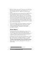
T1 LEDs on the TR114+P8V-T1
In addition to the channel LEDs, the TR114+P8V-T1 has two banks
of T1 LEDs that provide information about T1 errors when they
occur. The T1 service LEDs project through the mounting bracket as
shown in Figure A-1.
The T1 transmission LEDs are located on the top left of the board (see
Figure 2-3 for the location). These LEDs indicate T1 errors as
described in T1 Transmission LEDs on page A-5.
A-1
0
2
4
6
Channel
LEDs
1
3
5
7
Loopback switch
TE S T
D1
D3
D2
D4
T1 connector
Figure A-1. TR114+P8V-T1 Mounting Bracket with LEDs
T1 Service LEDs
The LEDs labeled D1 through D4 provide information on the T1
service. These LEDs are described in Table A-1.
Table A-1. T1 Service LED Activity
LED Color
Indicates
D1
Red
TR114+P8V-T1 in network loopback mode.
D2
Red
Loss of T1 network signal.
D3
Yellow
TR114+P8V-T1 failing to synchronize on
incoming T1 signal, and sending yellow
alarm.
D4
Green
TR114+P8V-T1 receiving error-free T1.
When the TR114+P8V-T1 is operating in normal mode under
error-free conditions, only D4, the green LED, is lit. If there are
problems, D4 will not be lit. Instead you will encounter one of the
following conditions.
A-2 TR114 PCI Digital Hardware Manual
Solution
A-3
Yellow LED (D3)
The board cannot detect
and red LED (D2) are a valid T1 signal.
lit.
1. Ensure that the cable between the network card and T1 is the
correct type. For information on the correct type of cable, see
Connecting the P8V-T1 to the T1 Telephone Service on page 3-1.
2. Ensure that the cable pinouts are correct between the
TR114+P8V-T1 and the T1 service connector. See
Pinouts for the T1 Connector on page 3-3. The tip transmit pin on
the T1 should be mapped to the tip receive pin on the P8V-T1 and
the ring transmit pin should be mapped to the ring receive pin.
3. Ensure that your T1 service is up and running correctly.
4. Ensure that the P8V-T1 board is not in loop-back mode during
testing.
Interpreting LEDs
Red LED (D2) is lit
1. Check the TR114+P8V-T1’s cabling and connection to the CSU or
T1 wall jack.
2. Check the configuration of the CSU.
Condition
Flashing Green LED
Description
Loss of signal from the
T1 network
Check to see if the clocking parameters match what your T1 provider
is set up to provide.
Description
Solution
Yellow LED (D3) is lit.
The board cannot
synchronize on the T1
signal it is receiving
Possible causes are:
- Loss of T1 signal.
- T1 signal has an invalid framing pattern.
- T1 signal contains severe errors.
- T1 signal contains Blue Alarm (all 1s) pattern.
- AMI/B8ZS, SF/ESF setup parameters of the T1 service do not
match what the TR114+P8V-T1 is set up to receive.
Check for proper network clock configuration in the T1 signal from
the Central Office or from the PBX.
Green LED lit but data is A clocking conflict
1. Check Switch 1 of SW2 for the T1 clock master configuration.
not received or sent to
between the board and the
Unless the TR114+P8V-T1 is connected to a PBX, configure the
the T1 service.
T1 service, caused by both
TR114+P8V-T1 so that the T1 is the clock master.
sides generating and
2. Check the PBX or Telco to ensure that the T1 line is up and running
sending T1 clock signals,
may prevent the board
from synchronizing. When
the TR114+P8V-T1 fails
to synchronize, it will not
receive or send data to the
T1 network properly.
A-4 TR114 PCI Digital Hardware Manual
Condition
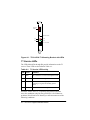
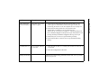
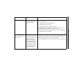
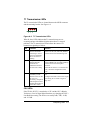
T1 Transmission LEDs
CRC
BPV
FRM
The T1 transmission LEDs are located between the MVIP connector
and the mounting bracket. See Figure A-2.
Figure A-2. T1 Transmission LEDs
When lit, these LEDs indicate that T1 transmission errors are
occurring and provide additional information about T1 network
problems. The T1 transmission LEDs indicate the status of T1
transmission signaling as follows.
LED
FRM
BPV
CRC
Indicates
T1 framing error
detected. Problems
connecting to the T1
circuit are frequently
due to incorrect T1
framing.
T1 bipolar violation
detected. Bipolar
violations are
sometimes related to
incorrect line coding.
Discrepancy in cyclic
redundancy check
detected. Noise on the
T1 line or an
incorrectly configured
cable length can cause
repeated discrepancies
in the CRC results.
Solution
Cycle switch 2 (frame mode) of SW2
between its SF (UP) and ESF (DOWN)
to detect and correct the framing error.
Cycle switch 3 (line coding) of SW2
between B8ZS (UP) and AMI (DOWN)
to detect and correct the bipolar
violation.
If the TR114+P8V-T1 is connected to a
CSU, check the configuration of the
CSU.
Ensure that there is no noise on the T1
line.
Configure the cable to the correct length
(see Setting the T1 Cable Length on
page 2-6).
CSU LEDs
If the TR114+P8V-T1 is attached to a CSU and the CSU’s Bipolar
Violation or Loss Of Signal lights illuminate, try changing the CSU’s
Line Build Out setting. The choices are usually 0dB, -7dB, -15 dB,
and -22.5 dB.
Interpreting LEDs
A-5
Appendix B
North American Standards
Compliance
Note to developers, system integrators, value added resellers, and
distributors: The following compliance information must be provided
to your customer and the end user as part of your system
documentation.
The Federal Communications Commission (FCC) in the United
States and Industry Canada (IC) in Canada regulate all electronic
devices that connect to the telephone system and/or generate radio
frequency signals. The TR114 is such a device and must comply with
the regulations specified below.
Telephony Regulations
FCC Notices for Registered Component
Devices
This equipment is registered with the FCC under Part 68 as a
component device for use with a host PC. In order for the FCC
registration of this product to be retained, all other products used in
conjunction with this product must also be FCC Part 68 registered for
use with these hosts. If any of these components are not registered,
then you are required to obtain FCC Part 68 registration of the
assembled equipment prior to connection to the telephone network.
Part 68 registration requires that you maintain this approval and as
such are responsible for the following:
Any component added to your equipment, whether it bears
component registration or not, will require a Part 68 compliance
evaluation. You may need to test and make a modification filing to
the FCC before that new component can be used.
B-1
Any modification/update made by a manufacturer to any registered
component within your equipment, will require a Part 68 compliance
evaluation. You may need to test and make a modification filing to
the FCC before that modified component can be used.
If you continue to produce this component you are required to comply
with the FCC's Continuing Compliance requirements.
Therefore, it is recommended that only FCC Part 68 registered
devices bearing the 'CN' or 'CE' equipment code as part of the FCC
registration number, be used. To determine if your particular
components are appropriately approved, look for the FCC registration
number on all components and ensure that the equipment code '-CN-'
or '-CE-' is part of that number. Refer to the FCC Registration number
on this product as an example.
If the telephone company requests that you supply the FCC
Registration number and REN of the device you are connecting,
please supply the FCC Registration numbers from all component and
host devices that have a direct PSTN connection (i.e. have a REN
stated on the label) and the highest REN.
If at any time the ownership of this component device is transferred to
someone else (whether independently or as part of a system), supply
this manual to the new owner.
To ensure that the operation of the TR114 is compliant with FCC and
Industry Canada regulations use 0010 as the country_code in the
user defined configuration file btcall.cfg. Use of any other value for
the country code or modification of the BT_CPARM.CFG file in the
app.src directory may result in non-compliance of the board and
make its connection to the public telephone network illegal.
FCC Rules Regarding Fax Branding
The Telephone Consumer Protection Act of 1991 makes it unlawful
for any person to use a computer or other electronic device to send
any message via a telephone fax machine unless such message clearly
contains, in a margin at the top or bottom of each transmitted page or
on the first page of the transmission, the date and time it is sent; an
identification of the business, other entity, or individual sending the
message; and the telephone number of the sending machine, business,
entity, or individual.
B-2 TR114 PCI Digital Hardware Guide
Users:
To program this information into your fax machine,
follow the procedure described in your user manual.
Developers: You must include facilities in your application to
enable the user to enter the required information. Use
the API’s BfvFaxHeader function with the TR114 to
place this information on each transmitted page as
required. You must also include, in your user
manual, instructions for entering this information
into your system.
FCC Regulations For Connecting to a T1
Phone Line (Part 68)
The Federal Communications Commission (FCC) has established
rules that permit the TR114+P8V-T1 to be directly connected to the
telephone network:
• Standardized jacks are used for connections.
• This equipment may not be used on coin service provided by
the telephone company. Connection to party lines is subject
to state tariffs. (Contact your state public utility commission
or corporation commission for information.)
A malfunctioning circuit can harm the telephone network.
Disconnect a malfunctioning TR114+P8V-T1 board from the
telephone network until you determine the cause of the malfunction
and repair it. If a malfunctioning TR114+P8V-T1 remains connected,
the telephone company may temporarily disconnect service.
The CSU/DSU has been designed to prevent harm to the T1 network.
If the telephone company finds that the equipment is exceeding
tolerable parameters, the telephone company can temporarily
disconnect service, although they will attempt to give you advance
notice if possible.
If the telephone company alters their equipment in a manner that will
affect use of this device, they must give you advance warning so as to
give you the opportunity for uninterrupted service. You will be
advised of your right to file a complaint with the FCC.
North American Standards Compliance
B-3
Under the FCC rules, no customer is authorized to repair this
equipment. This restriction applies regardless of whether the
equipment is in or out of warranty.
Before connecting the TR114+P8V-T1 to telephone service, you
must give a representative of the local telephone company the
following information:
• The telephone numbers (Port ID) to which the
TR114+P8V-T1 is connected.
• SOC: 6.0F
• FIC: 04DU9-BN
04DU9-DN
1.544Mbps SF
1.544Mbps SF+B8ZS
04DU9-1KN 1.544Mbps ESF
04DU9-1SN 1.544Mbps ESF+B8ZS
• The type of wall jack required: USOC-RJ-48C
• The FCC Registration number: Labeled on back of board
IC Equipment Attachment Limitations (CS-03)
The Industry Canada label identifies certified equipment. This
certification means that the equipment meets certain
telecommunications network protective, operational, and safety
requirements. Industry Canada does not guarantee the equipment will
operate to the user's satisfaction.
Before installing this equipment, users should ensure that it is
permissible to be connected to the facilities of the local
telecommunications company. The equipment must also be installed
using an acceptable method of connection. In some cases, the
company's inside wiring associated with a single line individual
service may be extended by means of a certified connector assembly
(telephone extension cord). The customer should be aware that
compliance with the above conditions may not prevent degradation of
service in some situations.
Repairs to certified equipment should be made by an authorized
Canadian maintenance facility designated by the supplier. Any
repairs or alterations made by the user to this equipment, or
equipment malfunctions, may give the telecommunications company
cause to request the user to disconnect the equipment.
B-4 TR114 PCI Digital Hardware Guide
Users should ensure for their own protection that the electrical ground
connections of the power utility, telephone lines, and internal metallic
water pipe system, if present, are connected together. This precaution
may be particularly important in rural areas. Users should not attempt
to make installation connections themselves, but should contact the
appropriate electric inspection authority or electrician, as appropriate.
The Industry Canada certification number is found on the back of the
board.
Electromagnetic Emissions
This product was tested for emissions in a personal computer meeting
the limits of FCC Part 15, Class B. In order to ensure that it continues
to meet the Class A emissions limits it should be installed in a host
computer or other enclosure which also meets the Class B limits and
bears an FCC Part 15 registration number, a FCC logo and/or a CE
marking.
FCC Emissions Information
All computing devices utilizing clock frequencies in excess of 10 kHz
must be tested for compliance with RF emission limits set by the
FCC.
Changes or modifications to this unit not expressly approved by
Brooktrout Technology, Inc. could void the user’s authority to
operate the equipment.
Pursuant to Part 15 of the FCC Rules, this equipment has been tested
and found to comply with the limits for a Class A digital device.
These limits provide reasonable protection against harmful
interference when the equipment is operated in a commercial
environment. This equipment generates, uses, and can radiate radio
frequency energy, and if not installed and used in accordance with the
instruction manual, it may cause interference harmful to radio
communications. Operation of this equipment in a residential area is
likely to cause harmful interference, in which case, the user will be
required to correct the interference at his or her own expense.
North American Standards Compliance
B-5
IC Emissions Notice
This Class A digital apparatus complies with Canadian ICES-003.
Cet appareil numérique de la class A est conforme à la norme
NMB-003 du Canada.
Safety
The TR114 is recognized by ETL; the component recognition number
is on the back of the board. The TR114 has been tested and complies
with UL Standard 1950, Third Edition and with CSA Standard C22.2
No.950-95, Third Edition, Safety of Information Technology
Equipment, Including Electrical Business Equipment.
This product must be mounted in the final assembly so that it is
isolated from exposure to any hazardous voltages (voltages greater
than 42.4V peak or 60Vdc) within the assembly. Adequate separation
and restraint of cables and cords must be provided.
To maintain the safety certification of the system, ensure that the
power drawn from the power supply does not exceed its capacity.
Please refer to the power usage table elsewhere in this manual for
information on the voltages and currents required for proper
operation.
B-6 TR114 PCI Digital Hardware Guide
Appendix C
Developing Digital
Applications
This appendix describes:
• The MVIP and SCbus PCM buses and how the Brooktrout
API implements their operations.
• How to modify the digital.cfg file to set up the parameters
for the MVIP bus.
• How to use DNIS and dialing prefixes on T1 lines.
Developing and testing applications for a T1 environment does not
require T1 service. Because applications are not board-dependent,
you can develop and test T1 applications in Loop-Start or DID
environments initially and switch over to a T1 environment later.
PCM Buses
The TR114 PCI digital boards support the MVIP and SCbus PCM bus
protocols. A PCM bus carries digital telephone traffic between boards
housed within a PC. This digital traffic is received from and
transmitted to a T1 or E1 telephone line via a telephony network
interface card. On the TR114+P8V-T1, the T1 interface is built into
the board.
The NIC parses command signals (on-hook, off-hook, dial pulses,
and so on) from the incoming telephone line to pass to the host. The
application must handle all call progress before passing calls to the
TR114 boards connected to the bus.
C-1
The digital.cfg File
The digital configuration file, digital.cfg, contains PCM interface
configuration information that set general operation parameters.
digital.cfg is an ASCII file that you can create or edit with a text
editor. You can modify the example digital.cfg file or create your
own.
The first line of the digital configuration file consists of six integers
that set general configuration parameters. These parameters must be
entered sequentially, in the order shown in the table below. These
values apply to all channels on a TR114 board. The values for these
parameter settings are:
Parameter Value
mvip_peb For MVIP boards, use 1
For SCbus boards:
0 = PEB; 1 = SCSA.
law
0 = A-Law coding (Europe); 1 = µ-Law coding (U.S.).
robbed
0 – Required for MVIP and ignored for SCbus
(does not refer to robbed-bit signaling on the T1)
clock_rate For MVIP boards, use 1 (2.048 MHz).
For SCbus boards:
SCSA: 1 = 2.048MHz; 2 = 4.096MHz; 3 = 8.192MHz
PEB: 0 = 1.544 MHz (U.S.); 1 = 2.048 MHz (Europe).
sig_prot
0 = E&M (AT&T PUB 43801) wink start.
1 = E&M (AT&T PUB 43801) immediate start.
2 = FXS, Loop Start Mode (AT&T PUB 43801)
3 = FXO, Loop Start Mode (AT&T PUB 43801)
4 = Exchange Access North America (FG_D_EANA)
5 = Exchange Access International Signaling
(FG_D_EAIN)
6 = Operator Service Signaling (FG_D_OS)
7 = Terminating Protocol (FG_D_TERM)
Set this parameter according to your T1 telephone line
configuration.
Ignored for SCbus.
mf_freq
0 – Required for MVIP and ignored for SCbus.
C-2 TR114 PCI Digital Hardware Guide
The remaining lines of the digital configuration file consist of the
following parameters:
Parameter
Value
chan
TR114 channel number.
tstream*
MVIP transmit stream number for the channel; use the
even-numbered (data) MVIP stream you selected for
the TR114+P8V-T1 or TRNIC.
tslot
T1 transmit time slot number for the channel.
rstream
MVIP receive stream number for the channel; use the
even-numbered (data) MVIP stream you selected for
the TR114+P8V-T1 or TRNIC.
rslot
T1 receive time slot number for the channel.
* For information about using these parameters for SCbus, see Assigning
Time Slots to Resources on page C-8.
The example below shows the settings for MVIP boards (for
example, two P8V boards and one P8V-T1 board) with 24 channels (a
single T1 span) using data stream 6. The line that starts with # is a
comment line and does not affect the TR114/NIC operation.
# MVIP/PEB A/µ robbed clock_rate sig_prot mf_freq
#
1
1
0
chan
0
tstream
6
1
tslot
0
0
rstream
6
0
rslot
0
1
6
1
6
1
2
6
2
6
2
3
6
3
6
3
4
6
4
6
4
5
6
5
6
5
6
6
6
6
6
7
6
7
6
7
8
6
8
6
8
9
6
9
6
9
10
6
10
6
10
11
6
11
6
11
12
6
12
6
12
Developing Digital Applications
C-3
13
6
13
6
13
14
6
14
6
14
15
6
15
6
15
16
6
16
6
16
17
6
17
6
17
18
6
18
6
18
19
6
19
6
19
20
6
20
6
20
21
6
21
6
21
22
6
22
6
22
23
6
23
6
23
MVIP Bus Basics
The MVIP bus is a 40-wire ribbon cable. Sixteen of the MVIP cable's
forty serial wires carry data; these physical data lines correspond to
logical data units called data streams as defined by the MVIP bus
protocol.
The TR114 uses the MVIP configuration called channel-associated
signaling, which is shown in Figure C-1.
STR EA MS
connector
pin #
clocking
31
35
33
37
framing
7
8
9
10
DSO (0)
DSI (0)
DSO (1)
DSI(1)
fax & voice - out
fax & voice - in
signal - out
signal - in
11
12
13
14
DSO (2)
DSI (2)
DSO (3)
DSI (3)
fax & voice - out
fax & voice - in
signal - out
signal - in
15
16
17
18
DSO (4)
DSI (4)
DSO (5)
DSI (5)
fax & voice - out
fax & voice - in
signal - out
signal - in
19
20
21
22
DSO (6)
DSI (6)
DSO (7)
DSI (7)
fax & voice - out
fax & voice - in
signal - out
signal - in
T1 Telephony
Interface Card
T R 114- P 8V
Figure C-1. Channel-Associated Signaling Stream
Configuration
C-4 TR114 PCI Digital Hardware Guide
In this configuration, the sixteen streams are grouped into four sets of
four streams each. Each set contains two input and output pairs; each
pair consists of one data and one signaling stream, enabling the bus to
carry 128 separate voice, fax, data, or mixed channels.
The frame is the basic unit of a logical MVIP data stream (see
Figure C-2). A frame consists of thirty-two 8-bit time slots. A time
slot corresponds to one telephone call.
FRAM E
8 0 0 0 /s e c .
0
1
2
31
T im e s lo t s
3 2 /fr a m e
8 b it s / s l o t
Figure C-2. Basic Unit of a Logical MVIP Data Stream
Eight thousand frames are transmitted every second on a data stream.
This rate translates into a time slot transmission rate of 64,000 bps.
Thus, a stream carrying thirty-two time slots transmits at a rate of
2.048 Mbps.
How the API Implements MVIP Operation
At system startup, the Application Programming Interface (API)
loads each TR114 with parameters that designate which of the four
sets of streams will be used for data and which will be used for
signaling. The choices are streams 0/1, 2/3, 4/5, or 6/7. The first
stream in each pair transmits data, and the second stream in each pair
transmits signals.
During operation, the API selects a time slot from one of the streams
and associates it with one of the TR114's channels (for example, eight
slots must be selected and associated with an 8-channel board's eight
channels). Once time slots are associated, the TR114 monitors each
slot for incoming calls and transmits over each slot on outgoing calls.
Only calls on API-selected slots are monitored, so calls arriving on or
switched to unassociated slots are not answered.
Developing Digital Applications
C-5
Because each TR114 can use up to 32 time slots in one of the sixteen
data streams, up to 32 channels on any combination of 2-, 4-, 8-, 12-,
and 16-channel boards can be configured for operation on each
stream.
All TR114 channels on the same board must use the same data stream
and each slot in any stream can associate with only one TR114
channel in a system. Therefore, make sure no two TR114 channels,
either on the same board or on different boards, are associated (via the
API) with the same slot in the same stream; that is, slot x on stream A
must be associated with only one TR114 channel. If any changes in
slot-to-channel assignment are made during operation, these changes
must be coordinated with all devices that use the affected slots or with
any switching or network devices. Unique slot-to-channel association
must be ensured and maintained.
We recommend making a one-time slot assignment via the digital.cfg
file if you are using Brooktrout TRNIC boards. If you are using
another manufacturer’s telephony network interface card, we
recommend using dynamic reassignment of slot-to-channel
associations via the API.
SCbus Basics
The SCbus protocol logically divides the cable’s twenty-six serial
wires into the Data Bus, which carries data, and the Message
Channel1, which carries messages between boards or between board
components. All physical wires on the Data Bus and the Message
Channel correspond to logical units called streams.
The Data Bus carries data on sixteen bi-directional streams. The Data
Bus can transfer data at 2.048 Mbps, 4.096 Mbps, or 8.192 Mbps.
However, the nominal speed of ribbon cable implementations is
4.096 Mbps. Only backplanes that achieve correct signal termination
can run at 8.192 Mbps. Depending on the data transfer rate used, the
SCbus can carry 512, 1024, or 2048 separate voice, fax, data, or
mixed channels.
1. The TR114 board does not support this feature.
C-6 TR114 PCI Digital Hardware Guide
S tre am s
connector
pin #
S C LK x2*
GND
S C LK
Re served
F S Y NC*
CL K F A IL
SD 0
GND
SD 1
SD 2
SD 3
SD 4
SD 5
SD 6
GND
SD 7
SD 8
SD 9
S D 10
S D 11
GND
S D 12
S D 13
S D 14
S D 15
M C D ata
1
2
3
4
5
6
7
8
9
10
11
12
13
14
15
16
17
18
19
20
21
22
23
24
25
26
T1 Telephony
Interface Card
T R 1 14-P 8S
Figure C-3. SCbus Distributed Signaling Configuration
The frame is the basic unit of a logical SCbus data stream. A frame
consists of 32, 64, or 128 8-bit time slots. A time slot corresponds to
one telephone call.
FR A M E
8 0 0 0 /s e c .
0
1
2
31
T i m e s lo t s
3 2 / fr a m e
8 b its / s lo t
Figure C-4. Basic Unit of a Logical SCbus Data Stream
Operating at 2.048 Mbps
FR A M E
8 0 0 0 /s e c .
0
1
2
63
T i m e s lo t s
6 4 /f r a m e
8 b its /s lo t
Figure C-5. Basic Unit of a Logical SCbus Data Stream
Operating at 4.096 Mbps
Developing Digital Applications
C-7
Eight thousand frames are transmitted every second down a data
stream. This rate translates into a time slot transmission rate of 64,000
bps. Thus, a stream carrying 32 time slots transmits at a rate of 2.048
Mbps, and a stream carrying 64 time slots transmits at a rate of 4.096
Mbps.
Implementing SCbus Operation
The TR114 is designed to use the distributed switching architecture
(SCSA) of the SCbus (see Figure C-3) or to emulate PEB operation.
The Brooktrout API provides parameters in the digital.cfg file to
support each mode (see The digital.cfg File on page C-2 and
Appendix C, Volume 2 of the Fax and Voice Application
Programming Interface).
The SCbus data path provides a point-to-point link between two
ports, enabling:
• Association of any T1 time slot to any SCbus time slot.
• Ports to use any SCbus time slot to transmit or receive data.
• Only one port at a time to transmit data on a particular time slot.
• Any number of ports to receive data from the same time slot.
• Any port to reroute an incoming call on a T1 time slot to an
outbound call on another T1 time slot.
Assigning Time Slots to Resources
All resources on the SCbus have a transmit time slot and a receive
time slot. A full duplex connection is created between two resources
when the transmit time slot of each resource links to the other’s
receive time slot.
At initialization, the switch handler, software on the NIC, selects the
time slots the NIC will use to transmit data over the SCbus, and these
time slots remain assigned to the NIC until the system is powered off.
Only the NIC can transmit data over these selected time slots.
You assign the time slots the TR114 channels will use to transmit
data (tslot) and the time slots it will use to receive data (rslot) in
the digital.cfg file.
C-8 TR114 PCI Digital Hardware Guide
Since the NIC takes its transmit time slots at initialization, it
determines which time slots other resources can use to transmit data.
So, to avoid conflicts, before you assign transmit and receive time
slots to the TR114, query your NIC (see the vendor’s documentation
for instructions) for the transmit time slots it is using.
On the SCbus, the relationship between streams and time slots
depends on the clock rate used:
Table C-1. SCbus Stream and Timeslot Associations
SCbus Stream
2.048 MHz Time Slots 4.096 MHz Time Slots
0
0 – 31
0 – 63
1
32 – 63
64 – 127
2
64 – 95
128 – 191
3
96 –127
192 –255
4
128 – 159
256 – 319
5
160 – 191
320 – 383
6
192 – 223
384 – 447
7
224 – 255
448 – 511
8
256 – 287
512 – 575
9
288 – 319
576 – 639
10
320 – 351
640 – 703
11
352 – 383
704 – 767
12
384 – 415
768 – 831
13
416 – 447
832 – 895
14
448 – 479
896 – 959
15
480 – 511
960 – 1023
The tslot and rslot fields in the digital.cfg file are limited to two
digits, preventing use of the SCbus time slots 100 through 1023. To
work around this limitation, the API uses stream/time slot pairs. In
this scheme, time slot numbers in each stream begin at 0 and end at 31
or 63, depending on the clock rate used. Using stream 8 as an
example, Table C-2 shows how API time slots correspond to SCbus
time slots.
Developing Digital Applications
C-9
Table C-2. API Time Slot Numbering
SCbus Time slots
API Time slots
512
0
513
1
514
2
Stream 8
515
3
4.096 MHz
516
4
517
5
518
6
519
7
520
8
521
9
522
10
…
…
575
63
64 time slots/stream
For example, to assign TR114 channel 2 to transmit on SCbus time
slot 515 and to receive on time slot 521, enter the following
information in your digital.cfg file:
#
chan
tstream
tslot
rstream
rslot
2
8
3
8
9
Setting Up to Operate in PEB Mode
To operate in PEB mode, you must:
• Connect a PEB cable to the TR114’s SCbus connector.
• Specify PEB operation parameters in the digital.cfg file.
• Assign each TR114 channel an SCbus transmit and a receive time
slot via the digital.cfg file.
In digital.cfg, you must set the following three parameters:
• mvip_peb: 0
• law: 0 = A-Law decoding; 1 = µ-Law decoding
• clock_rate: 0 = 1.544, 1 = 2.048
C-10 TR114 PCI Digital Hardware Guide
The other parameters are ignored.
Although you can assign transmit and receive time slots
independently of each other, you must always assign stream 0 to
transmit (tstream ) and stream 1 to receive (rstream). The
Brooktrout API automatically makes these stream assignments when
mvip_peb is 0.
Thus, depending on the clock rate used, in PEB mode the TR114 can
use SCbus time slots 0 through 23 (1.544 MHz) or 0 through 31
(2.048 MHz) only.
So, to define and assign TR114 channel 2 SCbus time slot 14 to
transmit on and time slot 24 to receive on, you would enter this
information in your digital.cfg file:
# chan tstream
tslot
rstream
rslot
2
0
14
1
24
If you enter a value other than 0 in tstream and 1 in rstream, the
Brooktrout API ignores it and uses the correct values when the value
of mvip_peb is 0.
Setting Up to Operate in SCSA Mode
To operate in SCSA mode, you must:
• Connect an SCbus cable to the TR114’s SCbus connector.
• Specify SCSA operation parameters in the digital.cfg file.
• Assign each TR114 channel an SCbus transmit and a receive time
slot via the digital.cfg file.
In digital.cfg, you must set the following three parameters:
• mvip_peb: 1 (SCSA)
• law: 0 = A-Law decoding; 1 = µ-Law decoding
• clock_rate: 1 = 2.048, 2 = 4.096, 3 = 8.192
The other parameters are ignored.
To define and assign TR114 channels’ SCbus transmit and receive
time slots, you enter transmit and receive stream/time slot pairs as
described in Assigning Time Slots to Resources.
Developing Digital Applications
C-11
How the API Implements SCSA and PEB
Modes
During channel reset, the API loads each TR114 with operation
parameters; one of these parameters designates the clock rate to use.
Depending on the mode specified, the choices are 1.544 MHz, 2.048
MHz, 4.096 MHz, or 8.192MHz. According to the clock rate
specified, each of the SCbus’ sixteen data streams carries 24, 32, 64,
or 128 time slots to interface with those of the T1 or E1 network. For
each stream, SCbus time slots are numbered from 0 to 23, from 0 to
31, from 0 to 63, or from 0 to 127.
During operation, the API selects a transmit time slot and a receive
time slot from one or more streams and associates it with one of the
TR114's channels (sixteen slots for an 8-channel board, eight slots for
a 4-channel board, and four slots for a 2-channel board). Once time
slots are associated, the TR114 monitors each receive slot for
incoming calls and transmits over the transmit slots for outgoing
calls. Only calls on API-selected slots are monitored, so calls arriving
on or switched to unassociated slots are ignored.
The application can change time-slot-to-channel assignments during
operation, but it must coordinate these changes with other resources
that use the affected time slots. Full duplex paths require transmit
time-slot-to-receive time slot connections between the NIC and
resource. And, while only one resource at a time can transmit on the
same time slot, no resource can transmit on any of the NIC’s transmit
time slots.
Each time the system reboots, you must query the NIC for its time
slot assignments before you run your application, whether you use the
previous time slot-to-channel assignments or new ones.
Using DNIS on T1 Lines
Dialed Number Identification Service (DNIS) is a common option on
T1 lines that use DTMF to transmit digits. Like Direct Inward Dial
(DID) on analog telephone lines, on incoming calls, DNIS transmits
the last few digits of the dialed number to the receiver, providing
information useful for routing faxes in LAN-FAX applications.
C-12 TR114 PCI Digital Hardware Guide
When you purchase your T1 service with DNIS, you specify how
many DNIS digits you want the telephone company to transmit. Then
you must configure the TR114 for the same number of DNIS digits
through software.
• For third party applications, see the documentation that came
with it for instructions on how to configure the TR114 for DNIS
digits. Brooktrout maintains a list of digital TR114 configuration
settings for specific LAN-FAX applications. To obtain this list,
call the Brooktrout Technical Support Fax-On-Demand system at
781-449-9010.
• For API applications, you configure the DNIS digits with the
did_digits keyword in the btcall.cfg configuration file. (See
the example btcall.cfg configuration file in the sample application
directory bfax\app.src.) You can change this parameter at any
time without executing a hardware or simulated hardware reset.
• For the DOS test program, faxtest, configure the DNIS
digits with the did_digits keyword in the user.cfg
configuration file.
Using Dialing Prefixes to Dial Out
Another T1 option provides dial tone to a channel when the channel
goes off-hook. Because of dialing prefixes, it is useful to know if your
T1 service includes this option.
For all applications, note that a dialing prefix inserted at the
beginning of the dial string controls how the TR114 dials out.
Prefix
Action
w
1. If w is the first digit in the dial string, checks the
availability of the time slot or wink.
2. If w is other than the first digit in the dial string, waits for
the dial tone before dialing the first digit in the dial string
,
Delays one second before dialing the first digit in the dial
string.
Developing Digital Applications
C-13
If your T1 service provides dial tone, we recommend that you insert
ww before the first digit in your dial string so that the TR114 will
check the availability of the time slot and then wait for the dial tone.
If your service does not provide dial tone or if you are not sure, we
recommend that you insert w, before the first digit in your dial string
so the TR114 will check for the availability of the time slot and then
delay one second.
For third party applications, see the documentation that came with it
for information about the dialing prefixes it uses.
C-14 TR114 PCI Digital Hardware Guide
Appendix D
Using Two or More
NICs on the MVIP Bus
In rare cases, you may have to put two or more NICs on a single
MVIP bus. Be aware that each resource board (such as TR114
boards) connected to that MVIP must be configured to transfer data
on all channels through only one NIC.
This appendix describes some of the issues involved and how to
configure the TR114+I8V-T1 so that it functions properly.
Setting MVIP Clock Master (MASTR)
The MASTR switch (switch 3 of SW3) controls whether the
TR114+I8V-T1 being configured is the MVIP clock master. The
clock master generates clocking signals to the MVIP bus. Only one
NIC can be set to be the clock master.
MASTR
UP
DOWN
Result
The TR114+I8V-T1 will generate the clocking
signals to the MVIP bus.
The TR114+I8V-T1 will not generate the clocking
signals to the MVIP bus.
Setting MVIP Clock Synchronization
Switch 4 (SEC8K) of SW3 is called the clock synchronization switch.
It can have one of two functions depending on the setting of the
MVIP clock master switch.
If the TR114+I8V-T1 being configured is designated as MVIP clock
master, it will be the NIC that synchronizes the MVIP clocks using a
T1 framing signal. It can use its own (clock sync UP) or another
NIC’s (clock sync DOWN) T1 framing signal.
D-1
If the TR114+I8V-T1 is not the MVIP clock master, its T1 framing
signal (the Sec. 8K signal) is output (clock sync DOWN) or is not
output (clock sync UP) to the MVIP bus, which may or may not use it
to synchronize the MVIP clocks. These switch states are shown in
Table D-1.
Table D-1. MVIP Clock Synchronization
MVIP clock
Clock sync
master switch switch
UP
DOWN
Result
UP
Sets the TR114+I8V-T1 to use its
own T1 framing signal to
synchronize the MVIP clocks.
DOWN
Sets the TR114+I8V-T1 to use the
T1 framing signal from another
network interface card to
synchronize the MVIP clocks.
UP
Prevents the TR114+I8V-T1 from
outputting its T1 framing signal to
the MVIP bus.
DOWN
Sets the TR114+I8V-T1 to output
its T1 framing signal to the MVIP
bus.
Setting Stream Selection
If you have more than one T1 line transmitting to more than one NIC
on a single MVIP, you may have to set different data/signal streams
for the different T1 lines. You set the streams using switches 1 and 2
of SW3. Once you have selected the streams on the TR114+I8V-T1,
you must edit the digital.cfg file for the TR114 boards (or its
equivalent for other resource boards) to ensure that the data/signal
streams for the TR114s match the streams for the TR114+I8V-T1
through which the TR114 transfers data.
D-2 TR114 ISA Digital Hardware Guide
MVIP Clock Termination
Even if you have more than one NIC on the MVIP bus, the clock
termination requirements are basically the same as when you have a
single NIC on the bus. MVIP clock termination requirements depend
on the number of connections on the MVIP bus. Follow these
guidelines:
• Install the NIC designated as clock master at one end of the
cable.
• For systems with 5 or fewer MVIP bus connections,
terminate the resource board (such as a TR114) at the end
of the cable opposite the NIC. Make all other boards on the
cable unterminated including the clock master NIC and any
other NICs.
• For systems with more than 5 MVIP bus connections,
terminate both ends of the MVIP cable – the clock master
NIC and the resource board at the opposite end of the cable.
Make all other boards on the cable, including any other
NICs, unterminated.
Using Two or More NICs on the MVIP Bus
D-3
Index
A
adding another TR114 2-15
Attaching
MVIP bus 2-13
PCM bus 2-11
SCbus 2-13
B
Board ID, setting 2-8
Board layout
TR114+P16S 2-2
TR114+P16V 2-1
TR114+P2V 2-1
TR114+P8S 2-2
TR114+P8V 2-1
TR114+P8V-T1 2-2
Brooktrout software, installing
2-14
Btdriver.cnf 4-4
error conditions 4-11
Buses, PCM C-1
C
Cable length, T1 2-6
Cables
MVIP 2-12
SCbus 2-12
T1 3-4
crossover 3-5
straight-through 3-5
twisted 3-4
Changing the configuration
settings 2-3
Channel LEDS A-1
Channel service unit 3-2
Channels
identifying 4-5
testing 4-6
Clock
MVIP
master D-1
synchronization D-2
termination 2-4, D-3
termination switches
2-4
Configuration 2-1
btdriver.cnf file 4-3
changing settings 2-3
default settings 2-2
testing 4-4
Configurations 1-1
Index-1
configuring PCI board 2-15
Connection to the telephone
service 3-1
Connector
MVIP 2-12
RJ-45 3-3
SCbus 2-12
T1 3-3
Crossover T1 cable 3-5
pinouts 3-5
CSU 3-2
LEDs A-5
D
Data stream
MVIP C-5
SCbus C-7
Defaults, configuration 2-2
Dialing prefixes C-13
Digital applications,
developing C-1
digital.cfg file C-2
DNIS, using on T1 C-12
Downloading test software
5-2
E
E1
telephone service 3-1
EISA, configuring 2-15
Electromagnetic emissions
B-5
Environmental requirements
1-3
Error conditions
btdriver 4-11
faxtest 4-12
TR114+P8V-T1 4-10
Index-2
F
Fax
receiving test 4-8
sending test 4-8
Faxtest 4-7
command 4-7
error conditions 4-12
FCC
emissions information
B-5
notices B-1
regulations for connecting
to T1 B-3
rules for fax branding B-2
Features 1-1
H
Hardware requirements 1-3
I
IC
emissions notice B-6
equipment attachment
limitations B-4
Identifying the board 2-8
Installation 2-1
Installing
Brooktrout software 2-14
LAN Fax software 2-14
software 2-14
test software 4-2
TR114 board 2-11
Interpreting LEDs A-1
ISA boards
using with PCI boards
2-15
TR114 PCI Digital Hardware Guide
L
O
LAN Fax software, installing
2-14
LEDs
channel A-1
CSU A-5
interpreting A-1
T1 service A-2
T1 transmission A-5
TR114+P8V-T1 A-2
Loopback switch 4-10
Operating requirements 1-3
Options, T1 2-5
M
message log 4-9
Messages, test 4-4
multiple boards, using PCI
with ISA boards 2-15
MVIP C-4
attaching the bus 2-13
cabling specifications
2-12
clock master D-1
clock synchronization
D-1
clock termination D-3
switches 2-4
connector 2-12
data stream C-5
operation C-5
options 2-7
switches (SW3) 2-7
signaling configuration
C-4
stream selection D-2
termination 2-4
using two or more NICs on
D-1
P
PCI
using with ISA boards
2-15
PCM buses C-1
attaching to TR114 2-11
PEB mode, setting SCbus to
C-10
PEB resistors 2-11
Pinouts
crossover T1 cable 3-5
RJ-45 connector 3-3
straight-through T1 cable
3-6
T1 connector 3-3
twisted T1cable 3-4
R
Receiving a test fax 4-8
Replacing test software 4-10
Returning a TR114 board 5-2
RJ-45 connector 3-3
S
Safety B-6
SCbus C-6
attaching 2-13
cabling specifications
2-12
connector 2-12
operation C-8
PEB mode C-10
Index-3
SCSA mode C-11
signaling configuration
C-7
stream and timeslot
associations C-9
termination in PEB mode
2-10
termination in SCSA
mode 2-10
SCSA mode, setting SCbus to
C-11
Sending a test fax 4-8
Service information 5-1
Software
downloading 5-2
installing 2-14
installing Brooktrout
2-14
installing LAN fax 2-14
test 4-2
Standards compliance B-1
Straight-through T1 cable 3-5
pinouts 3-6
Stream selection, MVIP D-2
SW2, T1 options set with 2-5
SW3, MVIP options set with
2-7
Switches
MVIP options 2-7
MVIP termination 2-4
T1 options 2-5
T
T1
cable length 2-6
cables 3-4
connector pinouts 3-3
LEDs (TR114+P8V-T1)
A-1
Index-4
network connection 3-3
options 2-5
service LEDs A-2
telephone service 3-1
transmission LEDs A-5
using DNIS on C-12
Technical support 5-1
use of part numbers 5-1
use of test results 5-1
Telephone service
T1 and E1 3-1
Telephony regulations B-1
Termination
MVIP 2-4, D-3
SCbus in PEB mode 2-10
SCbus in SCSA mode
2-10
Test messages 4-4
Test software 4-2
downloading 5-2
installing 4-2
replacing 4-10
Testing
channels 4-6
configuration 4-4
TR114 4-1
TR114
+P16S board layout 2-2
+P16V board layout 2-1
+P2V board layout 2-1
+P8S board layout 2-2
+P8V board layout 2-1
+P8V-T1
board layout 2-2
error conditions 4-10
LEDs A-2
MVIP options 2-7
T1 options 2-5
configurations 1-1
TR114 PCI Digital Hardware Guide
environmental
requirements 1-3
features 1-1
hardware requirements
1-3
installing 2-11
operating requirements
1-3
returning 5-2
Testing 4-1
Troubleshooting 4-10
Twisted T1 cable 3-4
pinouts 3-4
Index-5