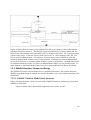
1
Master of Software Engineering Portfolio
By
Michael L. Fraka
B.S., University of Nebraska, 1982
MSE, Kansas State University, 2011
A PORTFOLIO
submitted in partial fulfillment of the requirements for the degree
MASTER OF SOFTWARE ENGINEERING
Department of Computing and Information Sciences
College of Engineering
KANSAS STATE UNIVERSITY
Manhattan, KS
2011
Approved by:
Major Professor
Dr. Scott DeLoach
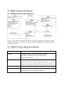
0 Abstract
The Goal Model for Dynamic Systems (GMoDS) is a means for specifying system requirements
for agent-oriented software at design time and tracking their achievement at run time. The
specification goal tree represents the specified requirements at design time. The instance goal
tree represents the run time achievement profile of the specified goals.
The GMoDS Visualizer is an optional graphical display of both the specification and instance
goal trees and all appropriate relations between the goals. In addition, the visualizer displays
goal parameters in both the specification and instance trees and the status and parameter values
of instance goals.
The GMoDS Test Driver tests either GMoDS or the GMoDS Visualizer. The Test Driver
executes event scripts from a file or by random generation compatible with the GMoDS model
being used. The Test Driver operates in automated or manual mode.
ii
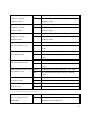
Table of Contents
0
ABSTRACT .......................................................................................................................................................II
1
CHAPTER 1 VISION DOCUMENT ...............................................................................................................4
2
CHAPTER 2 PROJECT PLAN ...................................................................................................................... 28
3
CHAPTER 3 SOFTWARE QUALITY ASSURANCE PLAN ..................................................................... 34
4
CHAPTER 4 ARCHITECTURAL DESIGN................................................................................................. 38
5
CHAPTER 5 TECHNICAL INSPECTION CHECK LIST ......................................................................... 69
6
CHAPTER 6 USE/OCL MODELING OF THE FORMAL SPECIFICATION ........................................ 72
7
CHAPTER 7 COMPONENT DESIGN .......................................................................................................... 82
8
CHAPTER 8 TEST PLAN ............................................................................................................................ 131
9
CHAPTER 9 ASSESSMENT EVALUATION ............................................................................................ 148
10
CHAPTER 10 USER MANUAL ................................................................................................................... 152
11
CHAPTER 11 PROJECT EVALUATION .................................................................................................. 174
12
REFERENCES ............................................................................................................................................... 181
iii
1 Chapter 1 Vision Document
1.1 Introduction
This paper provides the background, motivation, and specific system requirements for a
graphical visualization tool employable by software incorporating the Goal Model for Dynamic
Systems (GMoDS) [2] component. In addition, the paper specifies requirements for a test driver
for GMoDS that can substitute for simulation components as a client of GMoDS. Finally, the
paper concludes with assumptions, constraints, and the proposed development environment.
1.1.1 Motivation
Several simulations of agent-oriented systems using the GMoDS system exist but users of these
simulations have limited access to the state of GMoDS at run time. Developers of these
simulations would find GMoDS run time information invaluable as a debugging tool, but should
not be required to use this tool. The GMoDS Visualizer will provide a graphical representation
of GMoDS specification goals and run time instance goals with loose coupling to GMoDS
allowing for optional use.
Running an agent simulation is more complex and computationally expensive than is
necessary to test the Visualizer. The GMoDS Test Driver will test the GMoDS Visualizer by
stimulating GMoDS to in turn stimulate the Visualizer, thus allowing an alternative to simulation
clients as test mechanisms.
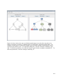
1.1.2 GMoDS
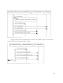
The GMoDS system represents system requirements as goals and their relationships using an a
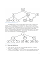
priori (i.e., prior to run time) specification tree. See Figure 1 [2] below. Higher level goals can
be decomposed into lower level goals using a parent/child relation, forming the tree. Parent
goals are related to child goals using either an AND or OR connective. Child goals connected
via AND must all be achieved to achieve the parent goal. Child goals connected via OR require
only one child to be achieved for the parent goal to be achieved. The specification tree goals can
be parameterized and are a template for goals created at run time; such run time goals are called
instance goals. Relationships between specification goals represent causal events (“triggers” that
create instance goals), negating events (“negative triggers” that cancel instance goals), and
ordering relations (“precedes” relations that force certain goals to be achieved before others).
4
Figure 1 GMoDS Specification Goal Tree [1]
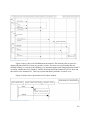
The GMoDS instance goal tree represents run time instances of the specification goal
templates, with any template parameters instantiated with values. See Figure 2 [2] below.
Instance goals are created in response to events that occur during execution of tasks that fulfill
goals and as a result of the relationships specified in the goal specification tree. A special “init
event” bootstraps the system, creating the initial instance goals that have no other trigger
specified. An instance goal tree represents parent/child relationships and can be color coded to
represent the status of a goal (triggered, active, achieved, failed, removed, or obviated) (see 0
below, terms and definitions, for explanation of these statuses).
Figure 2 GMoDS Instance Goal Tree [1]
1.1.3 Terms and Definitions
•
•
Instance goal state – the state of the instance goal within GMoDS (one of triggered,
active, achieved, failed, removed, or obviated).
Triggered – a goal is triggered by the “init event” if it has no other trigger. Otherwise, the
event associated with a “triggers” relation must occur while a task associated with the
5
•
•
•
•
•
•
goal at the source of the triggers relation is being executed for the goal to become
triggered.
Active – a goal becomes active if it is triggered and no precedes relation exists that points
to the triggered goal (or its ancestors) from an unachieved goal.
Achieved – a leaf goal is achieved when the agent executing the goal notifies GMoDS of
its achievement. A parent of child goals joined by “AND” is achieved when all of its
child goals are achieved. A parent of child goals joined by “OR” is achieved if any of its
child goals are achieved.
Failed – a leaf goal enters the failed status if the agent executing it notifies GMoDS of
failure to fulfill it.
Removed – a goal is removed from the instance tree as if it never existed if the event
associated with a negative trigger occurs during the execution of the goal that is the
source of the negative trigger and that trigger points to the specification goal that is the
template for the removed instance goal.
Obviated – a goal is obviated (made unnecessary to successful completion of its parent
goal) if a sibling goal is achieved when those siblings are connected by OR to their parent
goal.
Parameter value origin – the means by which the parameter value was established in
GMoDS (one of inherited, trigger, or modification). An inherited value comes from its
parent goal. A value with origin trigger comes from the triggering event. The origin
“modification” indicates the parameter value was modified.
1.2 Project Overview
1.2.1 Project Goal
The goal of this project is to provide an optional GMoDS run time information visualizer that
can be tested by multiple means. An additional project goal is to provide a GMoDS test driver
component that can test the visualizer by directly stimulating GMoDS substituting for a
simulation application component.
6
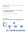
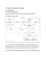
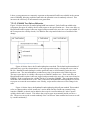
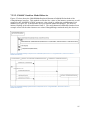
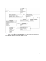
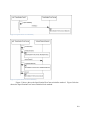
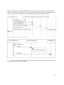
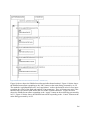
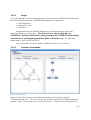
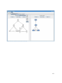
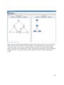
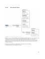
1.2.2 System Context
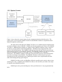
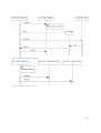
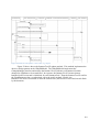
Figure 3 GMoDS Visualization Project System Context
Figure 3 above shows the system context for the components developed in this project. The
project goal is to develop the GMoDS Test Driver and GMoDS Visualizer components shown
shaded in light blue in this figure.
The figure shows that either the GMoDs Test Driver or a simulated agent component (but
not both) send goal events to GMoDS. GMoDS provides the possible goal events to the GMoDS
Test Driver. GMoDS pushes instance tree changes to the GMoDS Visualizer using a variant of
the Observer design pattern called ChangeManager. GMoDS already implements the client
portion of this design pattern. The GMoDS component provides the specification goal tree and
initial instance goal tree to the GMoDS Visualizer. The GMoDS Visualizer uses the specification
goal tree and instance goal tree as part of the “model” for its Model/View/Controller
architecture. The GMoDs Visualizer will display the specification goal tree and initial instance
tree and await changes from GMoDS. The GMoDS Visualizer will not import any layout
information from the goal diagram since GMoDS goal models can be programmatically built
rather than through parsing a goal diagram.
GMoDS Test Driver relies on GMoDS to define the possible goal events in order to issue
random goal events. In addition, the GMoDS Test Driver can check user-provided event scripts
for legality using GMoDS interfaces.
GMoDS parses the goal model diagram, if the specification tree is not programmatically
built.
7
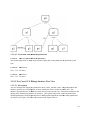
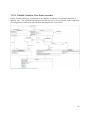
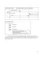
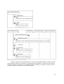
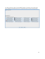
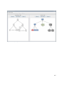
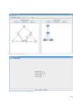
1.3 Project Requirements
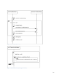
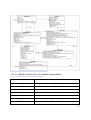
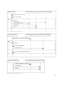
1.3.1 GMoDS Test Driver
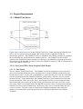
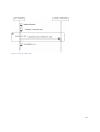
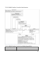
Figure 4 GMoDS Test Driver Use Cases
Figure 4 above shows use cases for the GMoDS Test Driver. When invoking the GMoDS Test
Driver, the user specifies the goal diagram that will be passed to GMoDS to build the
specification goal tree. The GMoDS Test Driver instantiates the GMoDS component, populates
the specification tree, and initializes the instance goal tree. The GMoDS Test Driver then
constructs the GMoDS Visualizer passing in a reference to the GMoDS component and to itself.
The reference to the GMoDS Test Driver causes the GMoDS Visualizer to add UI components to
control the GMoDS Test Driver.
1.3.1.1 Use Case GTD-1 Issue Scripted Goal Events
1.3.1.1.1 Description
The user selects “Load Event Script”. The GMoDS Test Driver prompts the user to provide a
goal event script that defines the goal events that will be issued to GMoDS and the delay time
between these events. It is the user’s responsibility to assure that the goal events are consistent
with the goal diagram but the GMoDS Test Driver will check the script for correct event and
parameter names. Upon initialization, the GMoDS Test Driver enters manual mode and waits
for user interaction. If the user clicks “Play”, the GMoDS Test Driver enters automatic mode
and executes the goal event script pausing for the specified delay time between events. If the
user clicks “Pause” in automatic mode, the GMoDS Test Driver event execution pauses and the
GMoDS Test Driver enters manual mode. If the user clicks “Next” in manual mode, the next
event is executed. The goal events are issued to the GMoDS component which alters the
instance tree based on the event and specification tree definition and informs the GMoDS
Visualizer.
8
1.3.1.1.2 Associated Functional Requirements
1.3.1.1.2.1 SR.GTD-1.1(Non-critical Requirement)
The GMoDS Test Driver shall prompt the user for a goal event script if the user selects “Load
Event Script” and if such a script is provided, the GMoDS Test Driver shall enter scripted event
mode (“Use Case GTD-1 Issue Scripted Goal Events”).
1.3.1.1.2.2 SR.GTD-1.2 (Critical Requirement)
The GMoDS Test Driver shall parse the goal event script to generate goal events, their
parameters, and the time delay relative to the previous goal event.
1.3.1.1.2.3 SR.GTD-1.2.1(Non-critical Requirement)
The GMoDS Test Driver shall log errors and drop the corresponding goal event from the script if
a goal event or parameter name does not match a legal name defined in the goal diagram. In
addition, the GMoDS Test Driver shall visually inform the user of these errors.
1.3.1.1.2.4 SR.GTD-1.2.2 (Critical Requirement)
The GMoDS Test Driver shall support a scripted events language with the following event types:
ACHIEVED, FAILED, and MODIFIED events for each active instance goal, and positive and
negative trigger events defined by the specification goal corresponding to any active instance
goal.
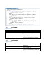
1.3.1.1.2.5 SR.GTD-1.2.3 (Critical Requirement)
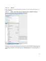
The GMoDS Test Driver Event Script Language (GTD-ESL) shall include the following XML
elements and attributes as shown in Figure 5 below and defined in the following requirements.
9
Figure 5 GMoDS Test Driver Event Script Language
1.3.1.1.2.5.1 SR.GTD-1.2.3.1 (Critical Requirement)
The GTD-ESL shall have a top-level “Script” element containing one or more “Event” element
children.
1.3.1.1.2.5.2 SR.GTD-1.2.3.2 (Critical Requirement)
The GTD-ESL “Event” element shall represent a single goal model event and have the following
attributes: “type” whose possible values are ACHIEVED, FAILED, POSITIVE_TRIGGER,
NEGATIVE_TRIGGER, or MODIFIED, “specGoal” whose value is the unique identifier of the
specification goal whose instance goal is achieved, failed, or from which the positive or negative
trigger emanates, “instGoal” whose value is the unique integer identifier of a particular instance
10
of the specification goal, “delay” whose value is the delay in milliseconds prior to issuing this
event to GMoDS (with minimum acceptable value of 1), and “name” whose value is the userdefined event name if the “type” is POSITIVE_TRIGGER or NEGATIVE_TRIGGER. If “type”
is MODIFIED, “instGoal” is the goal whose parameters are modified.
1.3.1.1.2.5.3 SR.GTD-1.2.3.3 (Critical Requirement)
The GTD-ESL “Event” element attributes “type”, “specGoal”, “instGoal”, and delay must be
provided.
1.3.1.1.2.5.4 SR.GTD-1.2.3.4 (Critical Requirement)
The GTD-ESL “Event” element attribute “name” must be provided if “type” has value
POSITIVE_TRIGGER or NEGATIVE_TRIGGER.
1.3.1.1.2.5.5 SR.GTD-1.2.3.5 (Critical Requirement)
The GTD-ESL “Event” element shall contain 0 or more “Parameter” element children.
1.3.1.1.2.5.6 SR.GTD-1.2.3.6 (Critical Requirement)
The GTD-ESL “Parameter” element shall represent the parameters of a positive or negative
trigger or “modifyInstanceGoal” event and have the following attributes: “name” whose value is
the parameter name and “value” whose value is the parameter value.
1.3.1.1.2.5.7 SR.GTD-1.2.3.7 (Critical Requirement)
The GTD-ESL “Parameter” element “value” attribute shall be treated as if the parameter’s data
type is a Java String.
1.3.1.1.2.5.8 SR.GTD-1.2.3.8 (Critical Requirement)
At least one GTD-ESL “Parameter” element must be provided if “type” is MODIFIED.
1.3.1.1.2.6 SR.GTD-1.3(Critical Requirement)
The GMoDS Test Driver shall cause GMoDS to populate its specification goal tree.
1.3.1.1.2.7 SR.GTD-1.4(Critical Requirement)
The GMoDS Test Driver shall cause GMoDS to initialize its instance goal tree.
1.3.1.1.2.8 SR.GTD-1.5(Critical Requirement)
The GMoDS Test Driver shall issue each goal event defined in the event script to GMoDS after
the specified delay time (milliseconds) relative to the previously issued goal event.
11
1.3.1.1.2.9 SR.GTD-1.6 (Critical Requirement)
Upon initialization of the GMoDS Test Driver in this use case, the GMoDS Test Driver shall
enter manual mode and await user interaction.
1.3.1.1.2.10 SR.GTD-1.6.1 (Critical Requirement)
If the user clicks “Play” in manual mode, the GMoDS Test Driver enters automatic mode and
begins to execute each event as defined in 1.3.1.1.2.8 above. If GMoDS Test Driver is in
random event operation, GMoDS Test Driver automatically generates a new random event and
executes it after the random delay time until the specified number of random events has been
issued.
1.3.1.1.2.11 SR.GTD-1.6.2 (Critical Requirement)
If the user clicks “Next” in manual mode, the GMoDS Test Driver issues the next unexecuted
goal event and waits for the next user interaction. If GMoDS Test Driver is in random event
operation and manual mode, the GMoDS Test Driver generates the next random event, appends
it to the currently executing script, issues the event to GMoDS, and waits for the next user
interaction.
1.3.1.1.2.12 SR.GTD-1.6.3 (Critical Requirement)
If the user clicks “Pause” in automatic mode, the GMoDS Test Driver enters manual mode and
waits for the next user interaction.
1.3.1.1.2.13 SR.GTD-1.6.4 (Critical Requirement)
If there are no more pre-defined events remaining or the specified number of random events have
been issued, the GMoDS Test Driver disables the “Play” and “Next” controls.
12
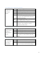
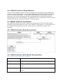
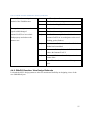
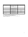
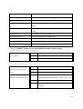
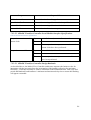
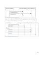
1.3.1.2 Use Case GTD-2 Issue Random Goal Events
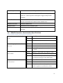
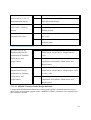
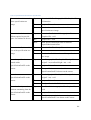
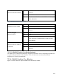
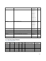
Table 1 below shows GMoDS Test Driver options to configure random events.
Table 1 GMoDS Test Driver Random Event Options
Option
Min String Length
Max String Length
Min Delay Time
Definition
Minimum length for a
String representing a
parameter value.
Maximum length for a
String representing a
parameter value.
Minimum delay time
between events.
Max Delay Time
Maximum delay time
between events.
Number of Random
Events
The total number of
random events to issue.
Default
1
Modified
While paused or in
manual mode.
10
While paused or in
manual mode.
1000 milliseconds (see
Table 2 page 17)
2
milliseconds (see Table
2 page 17)
25
While paused or in
manual mode.
While paused or in
manual mode.
While paused or in
manual mode.
1.3.1.2.1 Description
The user selects “Issue Random Events”. The GMoDS Test Driver replaces the currently loaded
event script with an empty script and begins random goal event generation. The GMoDS Test
Driver relies on the GMoDS component to discover the possible goal events based on the events
that have been issued to GMoDS. The “init” event provides the initial set of active instance
goals. The GMoDS Test Driver generates a random event as specified in the random event
configuration based on the current active instance goals and appends this event to the currently
executing event script. The GMoDS Test Driver issues the last-generated event to GMoDS,
according to “1.3.1.1.2.8 and 1.3.1.1.2.9” described above, after a random delay time, if GMoDS
Test Driver is in automatic mode or immediately if in manual mode. Upon execution of that
event, the “Use Case GTD-2 Issue Random Goal Events” resumes event generation until the
final random event is issued. The GMoDS Test Driver keeps the currently executing goal event
script which can be saved using the “Use Case GTD-3 Save Goal Event Script” described below.
Each active instance goal’s specification goal defines the positive and negative trigger events
that can be executed from that goal. In addition, the GMoDS Test Driver can issue an
ACHIEVED, FAILED, or MODIFIED event for each active instance goal. The union of all
positive and negative trigger, ACHIEVED, FAILED, and MODIFIED events defined by all
active instance goals and their corresponding specification goals defines the possible random
events at any time.
1.3.1.2.2 Associated Functional Requirements
1.3.1.2.2.1 SR.GTD-1.1
See 1.3.1.1.2.1 above.
13
1.3.1.2.2.1.1 SR.GTD.2.1.1 (Non-critical Requirement)
The GMoDS Test Driver shall treat all parameter types as if they were String. That is, the
system shall make no attempt to generate a value of the type specified for the parameter in the
goal diagram. Instead, the type of the java object will be String for all parameter values. The
system will generate a random String for each parameter value.
1.3.1.2.2.1.2 SR.GTD.2.1.2 (Non-critical Requirement)
The GMoDS Test Driver may be configured with the minimum and maximum string lengths for
randomly generated strings. The system shall default to a minimum string length of 1 and a
maximum string length of 10.
1.3.1.2.2.1.3 SR.GTD.2.1.3 (Non-critical Requirement)
The GMoDS Test Driver may be configured with the minimum and maximum delay time in
milliseconds between randomly issued goal events. The system shall default to a minimum
delay time and maximum delay time defined relative to the default “Flash Period” from Table 2
on page 17. The minimum delay time shall default to the default “Flash Period” plus 1000
milliseconds. The maximum delay time shall default to twice the default “Flash Period”. The
system shall not accept a minimum delay time of less than the current “Flash Period” plus 100
milliseconds.
1.3.1.2.2.1.4 SR.GTD.2.1.4 (Non-critical Requirement)
The GMoDS Test Driver may be configured with the number of random goal events to issue.
The system will default to 25 random goal events to issue.
1.3.1.2.2.2 SR.GTD-1.3
See 1.3.1.1.2.6 above.
1.3.1.2.2.3 SR.GTD-1.4
See 1.3.1.1.2.7 above.
14
1.3.1.2.2.4 SR.GTD-2.2 (Critical Requirement)
The GMoDS Test Driver shall incrementally issue random goal events based on the current
active instance goals. The union of all positive and negative trigger, ACHIEVED, FAILED, and
MODIFIED events defined by all active instance goals and their corresponding specification
goals defines the possible random events at any time.
1.3.1.2.2.5 SR.GTD-2.3 (Critical Requirement)
The GMoDS Test Driver shall keep a history of randomly-generated goal events to form the
current event script being executed.
1.3.1.3 Use Case GTD-3 Save Goal Event Script
1.3.1.3.1 Description
The user selects “Save Script” and is prompted for a file in which to save the current goal event
script. If the user selects a file that exists, the GMoDS Test driver asks for confirmation that it
should overwrite that file. If the user selects a file name that does not exist or confirms the
overwrite operation, the GMoDS Test Driver saves the current goal event script to the file.
1.3.1.3.2 Associated Functional Requirements
1.3.1.3.2.1 SR.GTD-3.1 (Non-critical Requirement)
The GMoDS Test Driver shall provide a “Save Script” menu item that will cause the GMoDS
Test Driver to save the currently executing goal event script to a file.
1.3.1.3.2.2 SR.GTD-3.2 (Non-critical Requirement)
The GMoDS Test Driver shall allow the user to specify the file to contain the saved script.
1.3.1.3.2.3 SR.GTD-3.2.1 (Non-critical Requirement)
If the user selects a file that exists, the GMoDS Test driver shall ask for confirmation that it
should overwrite that file.
1.3.1.3.2.4 SR.GTD-3.2.2 (Non-critical Requirement)
If the user selects a file name that does not exist or confirms the overwrite operation, the GMoDS
Test Driver shall save the current goal event script to the file.
15
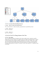
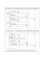
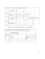
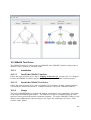
1.3.2 GMoDS Visualizer
Figure 6 GMoDS Visualizer Use Cases
Figure 6 above shows use cases for the GMoDS Visualizer. The client component (simulated
agent component or GMoDS Test Driver) instantiates the GMoDS component, populates the
specification tree, and initializes the instance goal tree. The client component then constructs the
GMoDS Visualizer passing in a reference to the GMoDS component. The GMoDS Visualizer
registers itself with GMoDS’ EventRegistry as the ChangeManager. The GMoDS Visualizer
displays the specification goal tree pulled from the GMoDS component. The GMoDS Visualizer
displays the initial instance goal tree provided by GMoDS and changes to the instance goal tree
pushed to it by GMoDS. The User can alter the appearance of the specification goal tree or
instance goal tree as a whole, change the appearance of a specific instance goal, or
collapse/expand a sub-tree of instance goals. Table 2 below shows the GMoDS Visualizer
options.
16
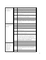
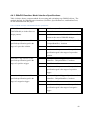
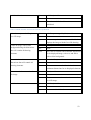
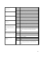
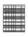
Table 2 GMoDS Visutalizer Options
Option
Flash Period
Definition
Total time a changed instance goal is
flashed.
Default
2 seconds
Modified
In manual mode.
Flash Cycle
Time between instance goal color
inversions in a single flash.
Show or hide parameter names and
types throughout the specification goal
tree.
Show or hide parameter names, values,
and origin throughout the entire
instance goal tree.
Show or hide particular specification
goals’ derived instance goals (a check
list of goal types to show is presented to
the user).
A triggered goal’s background color.
0.5 seconds
In manual mode.
Show
At run-time.
Show
At run-time.
Show
At run-time.
Specification Tree
Show/Hide Parameters
Instance Tree
Show/Hide Parameters
Show/Hide Instance
Goals of Particular
Specification Goals
Triggered Goal
Background
Triggered Goal
Foreground
Triggered Goal Flash
Background
Triggered Goal Flash
Foreground
Active Goal
Background
Active Goal Foreground
Active Goal Flash
Background
Active Goal Flash
Foreground
Achieved Goal
Background
Achieved Goal
Foreground
Achieved Goal Flash
Background
Achieved Goal Flash
Foreground
Failed Goal Background
Failed Goal Foreground
Failed Goal Flash
Background
Failed Goal Flash
Foreground
Removed Goal
Background
Removed Goal
Foreground
At run-time.
A triggered goal’s foreground color.
At run-time.
A triggered goal’s background color
during a flash.
A triggered goal’s foreground color
during a flash.
An active goal’s background color.
At run-time.
An active goal’s foreground color.
An active goal’s background color
during a flash.
An active goal’s foreground color
during a flash.
An achieved goal’s background color.
At run-time.
At run-time.
An achieved goal’s foreground color.
At run-time.
An achieved goal’s background color
during a flash.
An achieved goal’s foreground color
during a flash.
A failed goal’s background color.
A failed goal’s foreground color.
A failed goal’s background color during
a flash.
A failed goal’s foreground color during
a flash.
A removed goal’s background color.
At run-time.
A removed goal’s foreground color.
At run-time.
At run-time.
At run-time.
At run-time.
At run-time.
At run-time.
At run-time.
At run-time.
At run-time.
At run-time.
At run-time.
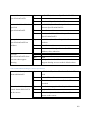
17
Option
Removed Goal Flash
Background
Removed Goal Flash
Foreground
Obviated Goal
Background
Obviated Goal
Foreground
Obviated Goal Flash
Background
Obviated Goal Flash
Foreground
Definition
A removed goal’s background color
during a flash.
A removed goal’s foreground color
during a flash.
An obviated goal’s background color.
Default
Modified
At run-time.
At run-time.
At run-time.
A removed goal’s foreground color.
At run-time.
A removed goal’s background color
during a flash.
A removed goal’s foreground color
during a flash.
At run-time.
At run-time.
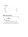
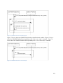
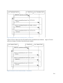
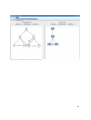
1.3.2.1 Use Case GV-11 Display Specification Tree
1.3.2.1.1 Description
The GMoDS Visualizer displays the specification tree including all goals, parent/child relatio
relations,
positive trigger relations, negative trigger relations, and precedes relations with their string
identifiers. The system uses the current setting for “Specification Tree Show/Hide Parameters”
to decide whether goal, positive trigger, and negative trig
trigger
ger parameter names and types are
shown. The default setting causes the system to display these parameters and types. See Figure
7 below.
Figure 7 Use Case GV-1
1.3.2.1.2 Associated Functional Requirements
18
1.3.2.1.2.1 SR.GV-1.1(Critical Requirement)
The system shall display the specification goal tree as a graphical tree using minimum white
space padding between adjacent tree elements. Each goal will have a white background and
black foreground lines and characters.
1.3.2.1.2.2 SR.GV-1.2 (Critical Requirement)
The system shall display the string name of all specification goals, parent/child connectives
(«and» and «or»), trigger events, negative trigger events, and precedes relations («precedes»).
1.3.2.1.2.3 SR.GV-1.3(Non-critical Requirement)
The system shall use the current “Specification Tree Show/Hide Parameters” setting to decide
whether to display the parameter name for goals or events.
1.3.2.1.2.4 SR.GV-1.4(Critical Requirement)
The system shall show all parent/child, precedes, positive trigger, and negative trigger relations
as lines connecting two specification goals.
1.3.2.1.2.5 SR.GV-1.5(Critical Requirement)
The lines connecting the source specification goal to the destination specification goal for
positive trigger, negative trigger, and precedes relations shall have an arrow head pointing to the
destination goal.
1.3.2.1.2.6 SR.GV-1.6(Critical Requirement)
Parent/child, precedes, and trigger relation lines shall be solid.
1.3.2.1.2.7 SR.GV-1.7(Critical Requirement)
Negative trigger relation lines shall be dashed.
1.3.2.1.2.8 SR.GV-1.8(Non-critical Requirement)
The system shall separate specification goal names from parameters using a horizontal line if
parameters are displayed. If parameters are not displayed no such horizontal line shall be shown.
1.3.2.1.2.9 SR.GV-1.9(Non-critical Requirement)
The system shall show for each specification goal each parameter name on its own single
separate line.
1.3.2.1.2.10 SR.GV-1.10(Non-critical Requirement)
19
The system shall show all event parameters on a single line between the opening parenthesis and
closing parenthesis separated by a comma. The final parameter shall be followed by the closing
parenthesis and no comma.
1.3.2.1.2.11 SR.GV-1.11(Critical Requirement)
Parent/child relation lines shall not intersect with each other.
1.3.2.1.2.12 SR.GV-1.12(Non-critical Requirement)
The system shall minimize the number of intersections between precedes, positive trigger,
negative trigger, and parent/child relation lines.
1.3.2.1.2.13 SR.GV-1.13(Critical Requirement)
The system shall not allow any lines to intersect goal rectangles.
1.3.2.1.2.14 SR.GV-1.14(Critical Requirement)
The system shall provide scrolling and zooming of the specification goal tree view.
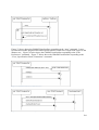
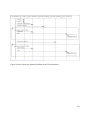
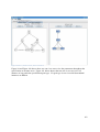
1.3.2.2 Use Case GV-2 Display Instance Tree
1.3.2.2.1 Description
The GMoDS Visualizer displays the initial instance goal tree in a tree-like structure including all
instance goals, and parent/child relations with their string identifiers. By default, goal parameter
names, values, and the values’ origin (I – inherited, T – trigger, M – modification) are shown.
The system shows each instance goal state visually. See Figure 8 below.
Figure 8 Use Case GV-2
20
1.3.2.2.2 Associated Functional Requirements
1.3.2.2.2.1 SR.GV-2.1(Critical Requirement)
The system shall display the instance goal tree as a graphical tree using minimum white space
padding between adjacent tree elements. Each instance goal will have a background color that
indicates the current state of the instance goal and black foreground lines and characters. The
state colors shall be as indicated in the “Legend” in Figure 8 above by default but shall be
editable at run time.
1.3.2.2.2.2 SR.GV-2.2(Critical Requirement)
The system shall display the instance goal name for each instance goal.
1.3.2.2.2.3 SR.GV-2.3(Non-critical Requirement)
The system shall display a collapse/expand toggle rectangle, if the instance goal has children,
centered on the lower edge of the instance goal. An instance goal displaying its children will
display the character “-“ in the collapse/expand toggle. An instance goal hiding its children will
display “+“ in the collapse/expand toggle.
1.3.2.2.2.4 SR.GV-2.4(Non-critical Requirement)
The system shall display a show/hide parameter toggle rectangle, if the instance goal has
parameters, centered on the left edge of the instance goal. An instance goal showing its
parameters will display the character “H” in the show/hide parameter toggle. An instance goal
hiding its parameters will display the character “S” in the show/hide parameter toggle.
1.3.2.2.2.5 SR.GV-2.5(Critical Requirement)
The system shall connect each parent instance goal to one of its child instance goals using a line
with an arrow pointing to the child, whose source is the collapse/expand toggle control on the
parent instance goal. The arrow head shall be centered on the top edge of the child instance goal.
1.3.2.2.2.6 SR.GV-2.6(Non-critical Requirement)
The system shall separate instance goal names from parameters using a horizontal line if
parameters are displayed. If parameters are not displayed no such horizontal line shall be shown.
1.3.2.2.2.7 SR.GV-2.7 (Non-critical Requirement)
The system shall show each instance goal parameter, parameter value, and parameter value
origin combination on a single line separated by a space, a semi-colon, and another space. One
21
line will be used for each combination of instance goal parameter, parameter value, and
parameters value origin.
1.3.2.2.2.8 SR.GV-2.8(Non-critical Requirement)
The system shall abbreviate the parameter value origin values as I (inherited), T (trigger), and M
(modification).
1.3.2.2.2.9 SR.GV-2.9(Critical Requirement)
The system shall provide scrolling and zooming of the instance goal tree view.
1.3.2.2.2.10 SR.GV-2.10 (Non-critical Requirement)
The system shall allow the user to specify that instance goals of particular specification goals be
shown or hidden.
1.3.2.2.2.11 SR.GV-1.11
See 1.3.2.1.2.11 above.
22
1.3.2.2.2.12 SR.GV-1.13
See 1.3.2.1.2.13 above
1.3.2.3 Use Case GV-3 Update Instance Tree
1.3.2.3.1 Description
The system receives notification from GMoDS that some aspect of the instance tree has changed.
The system modifies the display to reflect the changed information and flashes the affected
instance goals for a pre-determined period.
1.3.2.3.2 Associated Functional Requirements
1.3.2.3.2.1 SR.GV-3.1 (Critical Requirement)
The system shall flash all instance goals for which it has received a change for a pre-defined
period.
1.3.2.3.2.2 SR.GV-3.2 (Non-critical Requirement)
The default flashing period shall be 2 seconds. The default flashing cycle shall be 0.5 second.
Both the flashing period and flashing cycle shall be editable in manual mode.
1.3.2.3.2.3 SR.GV-3.3 (Critical Requirement)
The system shall flash an instance goal by changing its background and foreground from its state
color to its defined flash color and back once every flashing cycle. The user may avoid the
flashing effect by making the state and flash background and foreground colors match.
1.3.2.4 Use Case GV-4 Change Specification Tree View
1.3.2.4.1 Description
The user changes the display of parameters throughout the specification goal tree by selecting
hide or show parameters from a menu bar menu item. All specification goal and event parameters are hidden or shown as specified by the user. The system minimizes the display area
consumed by the tree at all times. The system reduces the size of elements that include
parameters when the parameters are hidden and expands the elements when parameters are
shown. See Figure 9 below and compare with Figure 7 above.
23
Figure 9 Use Case GV-4
1.3.2.4.2 Associated Functional Requirements
Req
1.3.2.4.2.1 SR.GV-4.1(Non-critical
critical Requirement)
The system shall show or hide all specification goal and event parameters as specified by the
user.
1.3.2.4.2.2 SR.GV-1.8
See 1.3.2.1.2.8 above.
1.3.2.4.2.3 SR.GV-1.9
See 1.3.2.1.2.9 above.
1.3.2.5 Use Case GV-55 Change Instance Tree View
1.3.2.5.1 Description
The user changes the display of parameters, their values, and the values’ origin throughout the
instance goal tree by selecting hide or show parameters from a menu bar menu item. All
instance goal parameters are hidden or shown as specified by the user. The system minimizes the
display area consumed by the tree at all times. The system reduces the size of elements that
include parameters when the parameters are hidden and expands the elements when parameters
are shown. See Figure 10 below and compare with Figure 8 above.
24
Figure 10 Use Case GV-5
1.3.2.5.2 Associated Functional Requirements
1.3.2.5.2.1 SR.GV-5.1(Non-critical Requirement)
The system shall show or hide all instance goal parameters as specified by the user.
1.3.2.5.2.2 SR.GV-2.6
See 1.3.2.2.2.6 above.
1.3.2.5.2.3 SR.GV-2.7
See 1.3.2.2.2.7 above.
1.3.2.6 Use Case GV-6 Change Instance Goal View
1.3.2.6.1 Description
The user toggles the display of parameters, their values, and the values’ origin for a specific
instance goal. The user clicks the view toggle control (a rectangle enclosing the letter S or H) on
a specific instance goal to toggle the display of parameters, their values, and the values’ origin.
The system minimizes the display area consumed by the tree at all times. The system reduces
the size of elements that include parameters when the parameters are hidden and expands the
elements when parameters are shown. See Figure 11 below where goal g5<2>’s parameters have
been hidden.
25
1.3.2.6.2 Associated Functional Requirements
1.3.2.6.2.1 SR.GV-6.1(Non-critical Requirement)
The system shall toggle the display of parameter names, value, and value origins for the specific
instance goal whose parameter display toggle control has been clicked.
1.3.2.7 Use Case GV-7 Change Instance Sub-tree View
1.3.2.7.1 Description
The user collapses or expands a specific instance goal sub-tree by clicking on its expand/collapse
toggle. When the system collapses a sub-tree it consumes less space in the display area. The
system redraws the instance tree with child elements of the specified goal removed if the
instance goal sub-tree is collapsed. A collapsed sub-tree draws its’ expand/collapse toggle as
“+”. An expanded sub-tree draws its’ expand/collapse toggle as “-“. A minimum white space
pad surrounds each visible instance goal, placing collapsed instance goal sub-trees as near as
possible to their peer instance goals. See Figure 11 below, where goal g5<2>’s sub-tree is
collapsed.
Figure 11 Use Cases GV-6 and GV-7
1.3.2.7.2 Associated Functional Requirements
1.3.2.7.2.1 SR.GV-7.1(Non-critical Requirement)
The system shall collapse the specific instance goal sub-tree hiding all descendant goals if the
user clicks on the collapse toggle control of that instance goal.
1.3.2.7.2.2 SR.GV-7.2(Non-critical Requirement)
26
The system shall expand the specific instance goal sub-tree showing all descendant goals whose
parent goal has not been collapsed, if the user clicks on the expand toggle control of that instance
goal.
1.3.2.7.2.3 SR.GV-7.3(Non-critical Requirement)
The system shall not change the expand/collapse state of any instance goal whose
expand/collapse control was not directly clicked.
1.3.3 Assumptions
•
•
There is no need to stack collapsed instance goals under instance goals from the same
specification goal. The view space savings from hiding the descendants will shrink the
displayed tree sufficiently to allow simultaneous viewing of the desired number of
instance goals.
Java JRE 1.6 or above will be available on platforms using the GMoDS Test Driver or
Visualizer.
1.3.4 Constraints
•
Applications using GMoDS shall not be forced to include the GMoDS Test Driver or
GMoDS Visualizer components in their projects but may optionally do so.
1.3.5 Environment
•
•
•
Application environment
o JDK 1.6 or higher available at http://www.sun.com/java.
Development environment
o Eclipse IDE for Java Developers
1.2.1.20090918-0703
GMoDS Version 2
o The GMoDS component is the GoalModel2 module in the CVS repository
cvs.projects.cis.ksu.edu at the repository path /cvsroot/gmods.
27
2 Chapter 2 Project Plan
2.1 Introduction
This is the final project plan for the GMoDS Visualizer and Test Driver Masters of Software
Engineering final project.
2.1.1 Terms
•
KSLOC – The size of source code in units of thousands of lines.
2.2 Project Phases
2.2.1 Inception Phase
The inception phase includes tasks to prepare a vision document, project plan, software quality
assurance plan, develop an initial prototype, and present the inception phase products to the
project supervisory committee.
The prototype will demonstrate a user interface for the GMoDS Visualizer that partially
implements the use cases “GV-1 Display Specification Tree”, “GV-2 Display Instance Tree”,
and “GV-3 Update Instance Tree”. The UI will also demonstrate the manual mode for the
GMoDS Test Driver using a hardwired event script.
The inception phase will conclude upon approval of the supervisory committee.
2.2.2 Elaboration Phase
The elaboration phase includes tasks to revise the vision and project plan documents, develop a
formal specification of one aspect of the software, prepare the architectural design document,
prepare a test plan, implement an executable architecture prototype, conduct a technical
inspection of one elaboration phase artifact, and present elaboration phase products to the
supervisory committee.
The executable architecture prototype will demonstrate the architecture of the software
on the critical requirements.
The elaboration phase will conclude upon approval of the supervisory committee.
2.2.3 Production Phase
The production phase includes tasks to prepare the component design document, develop the
remaining code and tests, conduct testing, evaluate the project, and present production phase
products to the supervisory committee.
The production phase presentation will include the production phase artifacts and a final
demonstration of the software.
28
The production phase will end upon approval of the supervisory committee.
2.3 Architecture Elaboration Plan
2.3.1 Revise the Vision Document
The student will incorporate changes suggested by the supervisory committee into the vision
document. The revised vision document will be submitted to the major professor for approval.
2.3.2 Revise the Project Plan
The student will revise the project plan to provide a detailed implementation phase plan and
revised cost estimate. The revised project plan will be submitted to the major professor for
approval.
2.3.3 Develop a Formal Specification
The student will formally specify the visibility and appearance of UI elements corresponding to
instance goals in response to GMoDS updates and user interactions using USE and OCL. The
formal specification will be submitted to the supervisory committee for approval.
2.3.4 Prepare the Architectural Design Document
The student will prepare an architectural design document to the level of abstraction of
component interfaces using appropriate diagrams. The architectural document will undergo
technical inspection and be submitted to the supervisory committee for approval.
2.3.5 Prepare the Test Plan
The student will prepare a test plan for the software to be executed in the production phase. The
test plan will include unit, integration, and component- and system-level functional tests.
The plan will include evaluation criteria for all critical use cases and a set of test data deemed
adequate for acceptance testing. Specifically, the test plan will identify a set of test cases, the types
of tests that will be used for these test cases, the data that will be used for each case, and the
requirement traces for each test case [6].
The test plan will be submitted to the supervisory committee for approval.
2.3.6 Conduct a Technical Inspection
The student will prepare an inspection checklist for the architectural design document and
coordinate the inspection with the inspectors. Kyle Hill and Shylaja Chippa will serve as
inspectors on this project. The inspection check lists and letters will be submitted to the
supervisory committee for approval.
2.3.7 Implement an Executable Architecture Prototype
The executable prototype will demonstrate the architecture for the critical requirements
established in the GMoDS Test Driver use cases “GTD-1 Issue Scripted Goal Events” and
“GTD-2 Issue Random Goal Events” and the GMoDS Visualizer use cases “GV-1 Display
Specification Tree”, “GV-2 Display Instance Tree”, and “GV-3 Update Instance Tree”. The
29
demonstration and presentation to the supervisory committee will expose the top technical risks
in the project.
2.4 Implementation Plan
2.4.1 Deliverables
The following deliverables will be provided in the production phase per course requirements [6].
2.4.1.1 Action Items
Action items identified during Presentation 2 will be resolved and documented.
2.4.1.2 User Manual
A user manual will be provided. Sections will include an overview and explanations of common
usage, user commands, error messages, and data formats.
2.4.1.3 Component Design
The internal design of the components will be documented consistent with their complexity
using class, sequence, and state chart diagrams.
2.4.1.4 Source Code
Well documented source code will be submitted consistent with the architectural and component
designs.
2.4.1.5 Assessment Evaluation
A test evaluation document will include descriptions of the testing, failures, and reliability
estimates. The document will include graphical depiction of software quality metrics.
2.4.1.6 Project Evaluation
A project review document will review both the process and product. The process review will
cover methodologies, cost estimation accuracies, and usefulness of technical reviews. The
product review will address whether the system requirements have been achieved and evaluate
the quality of the product.
2.4.1.7 References
The annotated bibliography will include cited references for all notations used in the portfolio.
2.4.1.8 Formal Technical Inspection Letters
Fellow MSE students Kyle Hill and Shylaja Chippa will provide letters including their formal
technical inspection checklist evaluations of this project and stating that the student in question
successfully participated in their MSE project as an inspector and that their projects (or at least
their formal technical inspection section) have successfully passed the architecture presentation.
30
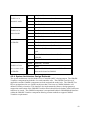
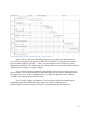
2.5 Work Breakdown Structure
Deliverable
Source code
Component Design
Task
Draw relations
between nonadjacent
specification
goals.
Implement
parameter origin
value (M)
“Modification”.
Revise event error
checking.
Log event script
errors
Visually notify
user of event script
errors.
Confirm overwrite
during save event
script.
Edit random event
parameters.
Edit state
parameters
View specification
tree parameters.
View instance tree
parameters
Expand/collapse
instance sub-trees.
Show/hide specific
instance goal
parameters.
Show/hide all
instances of
particular
specification goals
and their
descendants.
GMoDS Test
Driver Component
Design
GMoDS
Visualizer
Component
Design
Completion
Criteria
Executable code.
Time Frame
Time
9-14 Feb
4 days
Executable code.
15-17 Feb
3 days
Executable code.
18 Feb
0.5 day
Executable code.
18 Feb
0.5 day
Executable code.
22 Feb
1 day
Executable code.
23 Feb
0.25 day
Executable code.
23-24 Feb
2 days
Executable code.
25-28 Feb
2 days
Executable code.
1 Mar
0.5 day
Executable code.
1 Mar
0.25 day
Executable code.
2 Mar
1 day
Executable code.
3 Mar
1 day
Executable code.
4-7 Mar
2 days
UML diagrams.
8-9 Mar
1.5 days
UML diagrams.
9-10 Mar
1.5 days
31
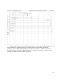
Deliverable
Task
Testing/Assessment Develop Unit
Evaluation
Tests
Develop test case
inputs
Run manual test
cases and resolve
issues.
Evaluate quality
metrics.
Document test
results.
Action Items
User Manual
All action item
resolutions
documented.
Installation guide
User guide
References
Formal Technical
Inspection Letters
Project Evaluation
All references
documented.
Send and receive
letters from formal
inspectors.
Evaluate process
and product.
Compile all
project artifacts
into an overall
portfolio
document.
Completion
Criteria
Unit tests
complete and
passed.
Inputs complete.
Time Frame
Time
11-17 Mar
5 days
18-22 Mar
3 days
All test cases
complete.
23-30 Mar
6 days
Quality metric
graphs complete.
All test case
documentation
complete.
All action items
resolved and
documented.
Approved by
Major Professor.
Approved by
Major Professor.
Approved by
Major Professor.
Approved by
Major Professor.
31 Mar
1 day
1-4 Apr
2 days
5 Apr
0.5 day
5-6 Apr
1.5 day
6-7 Apr
1.5 day
8 Apr
0.5 day
8 Apr
0.5 day
Approved by
Major Professor.
Approved by
Major Professor.
11-13 Apr
3 days
14 Apr
1 day
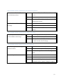
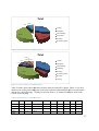
2.6 Cost Estimate
The project is at the end of the Elaboration Phase (phase 2). Table 3 below lists the productivity
for source code and documentation development in phases 1 and 2 of this project.
Table 3 Productivity in Phases 1 and 2
Activity Type
Source Code
Documentation
Reading/Research/Misc.
Project Time (hours)
85.7
68.5
24.5
178.7
Quantity
5000 SLOC
11 Documents
-
Productivity
58.4 SLOC/Hr
0.16 Doc./Hr
-
I have completed about 51 of 72 (71 %) functional requirements by the end of phase 2.
32
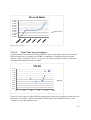
I estimate that the total SLOC required for the project near 7000 (5000/0.71 = 7059). So
approximately 2000 SLOC remain to be written.
I estimate about 36 hours of source code development using the productivity factor of 58.4
SLOC/Hr (2059/58.4 = 35.3 hours). Assuming work of 2 hours/day this translates to
approximately 18 days.
I estimate that developing unit tests should take approximately 10 hours (5 days), developing
manual test inputs 6 hours (3 days), running manual tests with the GMoDS Test Driver 6 hours
(3 days), and running manual tests with a simulation 6 hours (3 days) for a total of 14 days.
There are 5 major documents to produce in the Implementation Phase (component design,
assessment evaluation, user manual, project evaluation, and references). I estimate this will take
32 hours (5/0.16 = 31.25) or 16 days. So the total estimated time for phase 3 is 48 days.
2.6.1 Comparison of Cost Estimates
I initially estimated the code size as 3.3 KSLOC using unadjusted function points. The updated
code size estimate more than doubles the initial estimate. This discrepancy may be due to
inexperience with function point estimation and with the application area.
I initially made an estimate of the most likely the effort and time required using COCOMO 2.0.
The most likely time estimate was 7.8 months. The new time estimate places the project
conclusion in mid to late April which is well within that time frame.
33
3 Chapter 3 Software Quality Assurance Plan
3.1 Purpose
This is the initial software quality assurance plan for the GMoDS Visualizer and Test Driver
Masters of Software Engineering final project.
3.2 Management
3.2.1 Organization
The GMoDS Visualizer and Test Driver project is organized as follows.
•
•
•
•
Developer
o Mike Fraka
Major Professor
o Dr. Scott A. DeLoach
Supervisory Committee
o Dr. David Gustafson
o Dr. Robby
Technical Inspectors
o Shylaja Chippa
o Kyle Hill
3.2.2 Tasks
See Chapter 2 Project Plan for a discussion of all project tasks.
3.2.3 Responsibilities
3.2.3.1 Developer
The developer must produce all artifacts mentioned in 3.3.2 Minimum Documentation
Requirements as well as any additional documentation that may be required by the major
professor or supervisory committee. The developer must notify the major professor of any
technical risks found during conduct of the project.
3.2.3.2 Major Professor
The major professor must monitor the developer’s progress and provide guidance as needed. The
major professor is considered the primary user for the product.
3.2.3.3 Supervisory Committee
The supervisory committee must review and approve or provide necessary actions to remediate
all artifacts presented at the end of each phase of the project.
34
3.2.3.4 Technical Inspectors
The technical inspectors must inspect the architectural design document using the provided
checklist and provide the completed checklist and letter of inspection to the major professor and
a copy to the developer.
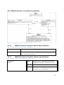
3.3 Documentation
All project documentation will be available at http://people.cis.ksu.edu/~mfraka/FrakaMSE.html.
3.3.1 Purpose
The purpose of the documentation is to provide a reference to the state of the project and the
engineering activities performed by the developer to date.
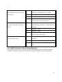
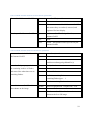
3.3.2 Minimum Documentation Requirements
Table 4 below shows the minimum documentation required for the GMoDS Visualizer and Test
Driver project.
Table 4 GMoDS Visualizer and Test Driver Minimum Documentation
Phase 1
Time Log
Vision Document 1.0
Project Plan 1.0
SQA Plan 1.0
Initial Executable Prototype
Presentation 1
Phase 2
Time Log
Vision Document 2.0
Project Plan 2.0
Architectural Design 1.0
Formal Requirements
Specification
Technical Inspection Checklist
Test Plan
Executable Architecture
Prototype
Presentation 2
Phase 3
Time Log
Component Design 1.0
Technical Inspection Letters
Project Evaluation
Project Source Code
Executable Project
User Manual
Presentation 3
3.4 Standards, practices, conventions, and metrics
The project will follow applicable IEEE standards ([4] [5]) for documents. The source code will
use Java naming conventions. The source code will be documented using javadoc. COCOMO
2.0 will be used as the cost estimation metric. Quality will be measured using the rework ratio
metric defined as:
!
Where EDefeects is the effort spent fixing defects and EDevelopment is the effort spent developing
code. Quality also will be measured using the mean time between defects. Both of these metrics
can be estimated using the engineering notebook time logs.
35
3.5 Reviews and audits
The developer will present all artifacts produced in each phase for review and approval by the
major professor and supervisory committee.
3.6 Test
The Test Plan will address all testing issues. Please refer to this document when it is produced.
3.7 Problem reporting and corrective action
The major professor may report problems to the developer at any time during the project. The
supervisory committee will report problems during each presentation. Any action items will be
documented and addressed in the next phase. Action items found at presentation 3 will be
addressed before project conclusion.
3.8 Tools, techniques, and methodologies
Table 5 below shows the tools, techniques, and methodologies employed in the GMoDS
Visualizer and Test Driver project.
Table 5 GMoDS Visualizer and Test Driver Tools, Techniques, and Methodologies
Tool
Microsoft Word 2007
Microsoft Excel 2007
Microsoft Power Point 2007
Microsoft Project 2002
XML Spy 2005
Gimp 2.2
Visual Paradigm for UML 7.0
Eclipse IDE for Java Developers
1.2.1.20090918-0703
Use
Prepare all written documents.
Prepare cost estimates.
Prepare custom figures.
Prepare Gantt charts.
Design XML schemas.
Customize images for insertion in documents.
Prepare UML diagrams and generate source code.
Develop source code.
JUnit 3.8
USE/OCL
Freemind 0.8.1
Develop and execute unit tests.
Formally specify UI element behaviors.
Record notes and ideas.
3.9 Code control, media control, and supplier control
Project artifacts produced using the Eclipse IDE (mainly source code, configuration files, and
tests) will be kept under version control using a Multiagent and Cooperative Robotics (MACR)
Laboratory CVS repository and accessed remotely.
Project artifacts produced using other tools (see Table 5 above) will be kept under version
control in a local CVS repository on the development machine and backed up at least weekly.
Supplier control is not applicable to this project.
36
3.10 Records, collection, maintenance, and retention
All project documentation (see 3.3.2 Minimum Documentation Requirements above) will be
available at http://people.cis.ksu.edu/~mfraka/FrakaMSE.html when completed. For access to
the most current version of GMoDS Visualizer and Test Driver artifacts, contact Dr. Scott
DeLoach.
3.11 Risk management
The developer and major professor share responsibility for identifying project risks and
communicating them to each other via email or phone.
37
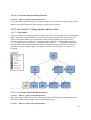
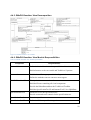
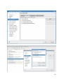
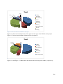
4 Chapter 4 Architectural Design
4.1 Introduction
4.2 System Architecture
This section documents the system architecture in a component diagram, lists module
responsibilities and interface specifications, and describes the design rationale.
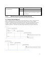
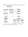
4.2.1 System Components
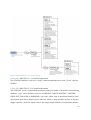
Figure 12 System components
Figure 12 System components shows the three components developed or reused in this project.
The system reuses the Goal Model for Dynamic Systems (GMoDS) component to
visualize its behavior. The exact version of GMoDS reused is specified in Chapter 3 Software
Quality Assurance Plan. The GMoDS component provides the GoalTree interface and requires
the ChangeManager interface. The client uses the GoalTree interface to pull information from
GMoDS. GMoDS uses the ChangeManager interface to push information to the client.
The GMoDS Visualizer component provides the user interface for visualizing the behavior
of GMoDS. Figure 12 notes show that the GMoDS Visualizer uses the Model-View-Controller
38
(MVC) architecture. The GMoDS Visualizer defines the TestDriver interface that must be
provided by the GMoDS Test Driver when the visualizer is tested using this component. The
GMoDS Visualizer provides the GMoDSVisualizer interface to support its initialization.
The GMoDS Test Driver component provides the TestDriver interface implementation to
support testing of the GMoDS Visualizer and uses the GMoDSVisualizer interface to initialize it.
4.2.2 System Component Responsibilities
Table 6 System component responsibilities
Component
GMoDS
Responsibilities
Provide the core objects and behaviors to be visualized.
Provide pull and push access to these core objects.
GMoDS
Provide the user interface for visualizing GMoDS object behaviors.
Visualizer
Provide the user interface controls for the GMoDS Test Driver if configured.
GMoDS Test
Provide the capability to test the GMoDS Visualizer in manual and automatic
Driver
mode.
4.2.3 System Interface Specifications
All interfaces throw an IllegalArgumentException if their preconditions are violated except for
the GMoDS Test Driver Launcher main program which prints an error message to the console
and exits if its preconditions are not met.
39
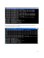
Table 7 GMoDS Test Driver Launcher interface specifications
Launch the GMoDS
Syntax:
main(args : string[]) : void
Test Driver for a
Pre:
args.length = 1
specific goal
Pre:
args[0] is the goal diagram file name.
diagram.
Pre:
args[0] is a file that exists and is readable.
Post:
The GMoDS component is created, initialized,
and passed to the GMoDSTestDriverImpl and
GMoDSVisualizerImpl.
Post:
The GMoDSTestDriverImpl is created and passed
to the GMoD Visualizer component.
Post:
The GMoDSVisualizerImpl is created and
initialized. The user interface is created,
initialized, and made visible.
Table 8 GMoDSVisualizer interface specifications
Initialize the
Syntax:
initialize() : void
GMoDS Visualizer
Pre:
GMoDS GoalTree implementation != null.
resulting in a
Pre:
GMoDS GoalTree implementation is initialized.
visible, ready user
Post:
The GMoDSVisualizerImpl is initialized. The
interface.
user interface is created, initialized, and made
visible.
Table 9 Test Driver interface specifications
Add an Observer of
Syntax:
addObserver(o : Observer) : void
the event script (as
Pre:
o != null.
in the Observer
Post:
An Observer o is recorded and will be notified
design pattern).
whenever the state of the EventScript changes.
40
Load an event
Syntax:
loadEventScript(eventScript : File) : void
script XML file into
Pre:
eventScript != null.
the TestDriver.
Pre:
eventScript File exists, is a File, and can be read.
Post:
An EventScriptImpl is created from the
eventScript File.
Post:
All valid GoalEvents specified in eventScript are
included in the EventScriptImpl
Post:
The TestDriver enters manual mode.
Post:
All invalid GoalEvents are discarded and the user
is notified visually and in a log file of discarded
GoalEvents.
Save the current
Syntax:
saveEventScript(eventScript : File) : void
event script as an
Pre:
TestDriver is in manual mode.
XML file.
Pre:
eventScript != null.
Pre:
User must have permission to write the
eventScript File.
Pre:
If eventScript File exists then user must confirm
that it will be overwritten.
Post:
The current EventScript of validated Goal Events
(events that have already been confirmed to refer
to instance goals that exist in GMoDS) will be
written to eventScript File using the XML schema
defined in Chapter 1 Vision Document.
Post:
The TestDriver remains in manual mode.
Begin issuing
Syntax:
issueRandomEvents() : void
random events
Pre:
None.
using the current
Post:
A RandomEventScriptImpl is created using the
random event
RandomEventParameters in effect during the
configuration
method call.
parameters.
Post:
The TestDriver enters manual mode.
41
Place the
Syntax:
play() : void
TestDriver in
Pre:
TestDriver is in manual mode.
automatic mode.
Pre:
TestDriver has a next GoalEvent it can issue.
Post:
The TestDriver enters automatic mode.
Place the
Syntax:
pause() : void
TestDriver in
Pre:
TestDriver is in automatic mode.
manual mode.
Pre:
TestDriver has a next GoalEvent it can issue.
Post:
The TestDriver enters manual mode.
Issue the next event
Syntax:
next() : void
to GMoDS.
Pre:
TestDriver is in manual mode.
Pre:
TestDriver has a next GoalEvent it can issue.
Pre:
The next GoalEvent refers to a valid instance
goal.
Post:
The TestDriver issues the next GoalEvent to
GMoDS.
Post:
The TestDriver remains manual mode.
Determine if the
Syntax:
hasNext() : boolean
TestDriver has a
Pre:
None.
next event to issue
Post:
Result = TestDriver has a next valid GoalEvent
to GMoDS.
that can be issued to GMoDS.
4.2.4 System Architecture Design Rationale
The system architecture uses the Model-View-Controller (MVC) design pattern. The GMoDS
Visualizer component has both the view and controller roles. The GMoDS Test Driver (if
applicable) and the GMoDS components are both assigned the model role. The GMoDS Test
Driver encapsulates the core GoalEvent objects that it can issue to GMoDS behind a welldefined TestDriver interface. This interface also implements the Observer design pattern to
support the notification of the GMoDS Visualizer that it should check whether valid GoalEvents
remain to be issued. The GMoDS component is encapsulated behind a GMoDSModel interface
within the GMoDS Visualizer component allowing custom methods to support GMoDS
Visualizer requirements.
42
4.3 GMoDS Test Driver Architecture
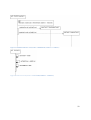
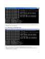
4.3.1 GMoDS Test Driver Decomposition
Figure 13 GMoDS Test Driver architectural modules
Figure 13 above shows the GMoDS Test Driver component architecture. Since this is a small
component and since it is used in the formal specification all GMoDS Test Driver modules are
shown in the diagram.
4.3.2 GMoDS Test Driver Module Responsibilities
Table 10 GMoDS Test Driver module responsibilities
Component
Launcher
Responsibilities
Configure GMoDS, GMoDSTestDriverImpl, and the
GMoDSVisualizerImpl. Initialize GMoDS and the
GMoDSVisualizerImpl.
GMoDTestDriverImpl
Hold an EventScript.
Implement loadEventScript and issueRandomEvents to create and
install EventScriptImpl and RandomEventScriptImpl, respectively.
EventScript
Define the behaviors of any EventScript.
EventScriptImpl
Hold the list of GoalEvents defining the script and provide default
implementations of the EventScript interface.
43
Component
RandomEventScriptImpl
Responsibilities
Override the EventScriptImpl to create and issue random
GoalEvents based on the RandomEventParameters configured by
the user and the events defined by the goal diagram.
GoalEvent
Define the behaviors of a GoalEvent.
EventType
Define the possible types of any event in a goal diagram.
GoalEventImpl
Implement the GoalEvent interface.
4.3.3 GMoDS Test Driver Interface Specifications
Table 11 GMoDS Test Driver GoalEvent interface specifications
Access the EventType of a
Syntax:
getType() : EventType
GoalEvent.
Pre:
None.
Post:
Result = this.eventType
Access the UniqueIdentifier
Syntax:
getSpecificationGoalIdentifier() : UniqueIdentifier
of the specification goal
Pre:
None.
referenced by a GoalEvent.
Post:
Result = this.specificationGoalID
Access the UniquieIdentifier
Syntax:
getInstanceGoalIdentifier() : UniqueIdentifier
of the instance goal
Pre:
None.
referenced by a GoalEvent.
Post:
Result = this.instanceGoalID
Access the UniqueIdentifier
Syntax:
getEventGoalIdentifier() : UniqueIdentifier
of the SpecificationEvent
Pre:
this.eventType =
referenced by a GoalEvent.
EventType.POSITIVE_TRIGGER or
this.eventType =
EventType.NEGATIVE_TRIGGER
Post:
Result = this.eventID
44
Table 12 GMoDS Test Driver EventScript interface specifications
Add an event valid with
Syntax:
addEvent(e : GoalEvent) : void
respect to the GMoDS
Pre:
e != null
specification tree to the end
Pre:
e is not already included in the script.
of the script.
Pre:
e.type is valid.
Pre:
if e.type = #MODIFIED then at least one
parameter must be provided for the event.
Pre:
e.getSpecificationGoalIdentifier() refers to a
specification goal that exists in the specification
tree.
Pre:
if e.type = #ACHIEVED then
e.getSpecificationGoalIdentifier() = ‘ACHIEVED’
and the specification goal is a leaf.
Pre:
if e.type = #FAILED then
e.getSpecificationGoalIdentifier() = ‘FAILED’ and
the specification goal is a leaf.
Pre:
if e.type != #MODIFIED then
e.getSpecificationEventIdentiifer() refers to an
specification event defined in the specification
tree.
Post:
(events – events@pre)->size() = 1
Post:
events.includes(e)
Post:
events.last() = e
Place the EventScript in
Syntax:
play() : void
automatic mode.
Pre:
EventScript is in manual mode.
Pre:
EventScript has a next GoalEvent it can issue.
Post:
The EventScript enters automatic mode.
45
Place the EventScript in
Syntax:
pause() : void
manual mode.
Pre:
EventScript is in automatic mode.
Pre:
EventScript has a next GoalEvent it can issue.
Post:
The EventScript enters manual mode.
Issue the next event to
Syntax:
next() : void
GMoDS.
Pre:
EventScript is in manual mode.
Pre:
EventScript has at least 1 event.
Pre:
EventScript has a next GoalEvent it can issue.
Pre:
The next GoalEvent refers to a valid instance goal.
Pre:
If next GoalEvent type != #MODIFIED then the
next event refers to a valid active instance goal.
Post:
If the next GoalEvent type != #MODIFIED the
EventScript issues the next GoalEvent to the
GMoDS event method.
Post:
If the next GoalEvent type = #MODIFIED the
EventScript issues the next GoalEvent to the
GMoDS modifyInstanceGoal method.
Post:
The EventScript index refers to the next event if
one exists.
Post:
The EventScript remains manual mode.
Determine if the EventScript
Syntax:
hasNext() : boolean
has a next event to issue to
Pre:
None.
GMoDS.
Post:
Result = EventScript has a next valid GoalEvent
that can be issued to GMoDS.
Add an Observer of the event
Syntax:
addObserver(o : Observer) : void
script (as in the Observer
Pre:
o != null.
design pattern).
Post:
An Observer o is recorded and will be notified
whenever the state of the EventScript changes.
46
4.3.4 GMoDS Test Driver Design Rationale
The heart of the GMoDS Test Driver is the EventScriptImpl and RandomEventScriptImpl that
extends it and the GoalEventImpl. The EventScriptImpl provides the deterministic (usually filebased) event script functionality. The RandomEventScriptImpl provides random GoalEvent
generation. The GoalEventImpl enforces the invariants that assure valid InstanceGoals and
SpecificationEvents are sent to GMoDS. The GMoDS Test Driver architecture was derived from
analysis of the objects referenced in Chapter 1 Vision Document.
4.4 GMoDS Visualizer Architecture
The GMoDS Visualizer uses the MVC architectural design pattern. Each section that follows
decomposes the modules that take on each role in the MVC design pattern. I did not make use of
the Command design pattern because the visualizer has no requirement to support undo
operations.
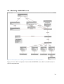
4.4.1 GMoDS Visualizer Model Decomposition
Figure 14 GMoDS Visualizer model modules
4.4.2 GMoDS Visualizer Model Module Responsibilities
Table 13 GMoDS Visualizer model module responsibilities
Component
Responsibilities
GoalState
Enumeration of possible goal states.
GMoDSModel
Define methods for access and evaluation of the core GMoDS
objects.
GMoDSModelImpl
Implement methods for access and evaluation of the core GMoDS
objects.
47
4.4.3 GMoDS Visualizer Model Interface Specifications
Table 14 below shows custom methods for accessing and evaluating core GMoDS objects. The
methods defined for GMoDS native interfaces (GoalTree, SpecificationTree, and InstanceTree)
are not documented in this paper.
Table 14 GMoDS Visualizer GMoDSModel interface specifications
Add an Observer of the
Syntax:
addObserver(o : Observer) : void
GMoDSModel (as in the Observer
Pre:
o != null.
design pattern).
Post:
An Observer o is recorded and will be notified
whenever the state of GMoDS changes.
Determine if any ancestor of the
Syntax:
specified specification goal is the
target of a precedes relation.
isAncestorPrecededSpecificationGoal(identifier
: UniqueIdentifier) : boolean
Pre:
identifier != null.
Post:
Result = true if any ancestor of the specified
specification goal is the target of a precedes
relation.
Determine if any ancestor of the
Syntax:
specified specification goal is the
target of a positive trigger.
isAncestorPositiveTriggeredSpecificationGoal
(identifier : UniqueIdentifier) : boolean
Pre:
identifier != null.
Post:
Result = true if any ancestor of the specified
specification goal is the target of a positive
trigger.
Determine if any ancestor of the
Syntax:
specified specification goal is the
target of a negative trigger.
isAncestorNegativeTriggeredSpecificationGoal
(identifier : UniqueIdentifier) : boolean
Pre:
identifier != null.
Post:
Result = true if any ancestor of the specified
specification goal is the target of a negative
trigger.
48
Determine if the two specified
Syntax:
specification goals do not have the
same parents.
isCrossTreeLink (identifier1 : UniqueIdentifier,
identifier2 : UniqueIdentifier) : boolean
Pre:
identifier1 != null.
Pre:
identifier2 != null.
Post:
Result = true if the two specified specification
goals do not have the same parents.
Determine if the two specified
Syntax:
haveSameParents (identifier1 :
specification goals have the same
UniqueIdentifier, identifier2 : UniqueIdentifier)
parents.
: boolean
Pre:
identifier1 != null.
Pre:
identifier2 != null.
Post:
Result = true if the two specified specification
goals have the same parents.
Evaluate the GoalState of the
Syntax:
specified instance goal.
assessState(identifier : UniqueIdentifier) :
GoalState
Pre:
identifier != null.
Post:
Result = the GoalState of the specified instance
goal.
4.4.4 GMoDS Visualizer Model Design Rationale
The GMoDS component is encapsulated behind a GMoDSModel interface within the GMoDS
Visualizer component to allow custom methods to support GMoDS Visualizer requirements.
49
4.4.5 GMoDS Visualizer View Decomposition
Figure 15 GMoDS Visualizer view modules
4.4.6 GMoDS Visualizer View Module Responsibilities
Table 15 GMoDS Visualizer view module responsibilities
Component
AbstractUI
Responsibilities
Define the basic behaviors and responsibilities of the view role.
Hold references to the core model and TestDriver if present.
AbstractCanvas
Hold the Java 2D image upon which a diagram is drawn.
Define the methods concrete canvases must support.
GMoDSVisualizerUI
The top level concrete user interface.
Hold the JFrame containing all visual components.
Provide the JMenuBar and host the TestDriver JToolBar.
Hold the SpecificationTreeUI and InstanceTreeUI in a JSplitPane.
SpecificationTreeUI
Define the UI for the specification tree.
Provide zoom and scroll controls for the specification tree.
SpecificationTreeCanvas
Draw the specification tree.
SpecificationGoalUI
Define the UI for a specification goal.
50
Component
AbstractRelationUI
Responsibilities
Define the basic behaviors of a relation UI between 2 specification
goal UIs. Used for positive and negative triggers and precedes
relations.
InstanceTreeUI
Define the UI for the instance tree.
Provide zoom and scroll controls for the instance tree.
InstanceTreeCanvas
Draw the instance tree.
InstanceGoalUI
Define the UI for an instance goal.
FlashDaemon
Flash added and changed instance goal UIs for the desired rate and
duration.
4.4.7 GMoDS Visualizer View Interface Specifications
Table 16 GMoDS Visualizer AbstractUI interface specifications
Create this view and all subordinate
Syntax:
createUI() : void
views.
Pre:
None.
Post:
This view and all subordinate views are created.
Create the appropriate controller for
Syntax:
makeController() : AbstractPart
this view.
Pre:
None.
Post:
Result = The appropriate controller for this view
is created.
Respond to notification of a change
Syntax:
update (o : Observable, arg : Object) : void
in the model.
Pre:
The Observable o (the model) has changed state.
Post:
This view makes appropriate changes to the
view based on changes in the Observable.
Register with the model if this view
Syntax:
registerWithModel() : void
needs to do so.
Pre:
None.
Post:
If this view needs to receive updates from the
model it registers as an Observer with it.
51
Initialize this view.
Syntax:
initialize() : void
Pre:
None.
Post:
This view and all subordinate views are
initialized.
Table 17 GMoDS Visualizer AbstractCanvas interface specifications
Paint the component holding the
Syntax:
paintComponent(g : Graphics) : void
Java 2D image.
Pre:
None.
Post:
This canvas paints the component it holds that
displays the image with the Java 2D drawing.
Create an image with a white
Syntax:
resize() : void
background using the dimensions
Pre:
None.
that will contain all drawing
Post:
This canvas calculates the minimum dimensions
elements.
for its displayed image, resizes it, and fills it
with a white background.
Determine the minimum
Syntax:
determineSize() : void
dimensions that will contain all
Pre:
None.
drawing elements.
Post:
The concrete canvas should calculate the
minimum dimensions for its displayed elements.
Draw viewed elements on the Java
Syntax:
draw() : void
2D image.
Pre:
None.
Post:
The concrete canvas draws its elements on the
Java 2D image.
Initialize the canvas.
Syntax:
initialize() : void
Pre:
None.
Post:
The canvas is initialized.
52
Table 18 GMoDS Visualizer SpecificationTreeCanvas interface specifications
Add an AbstractRelationUI to the
Syntax:
list of relations to draw.
addRelationUI(relationUI : AbstractRelationUI)
: void
Pre:
None.
Post:
The relationUI is added to the list of relationUIs
drawn on the canvas.
Draw the AbstractRelationUIs on
Syntax:
drawRelations() : void
the image.
Pre:
None.
Post:
All AbstractRelationUIs are drawn on the
canvas.
Table 19 GMoDS Visualizer SpecificationGoalUI interface specifications
Draw the SpecificationGoalUI and
Syntax:
drawTree(graphics2D : Graphics2D) : void
its descendants on the image.
Pre:
None.
Post:
This SpecificationGoalUI and its descendants
are drawn on the Java 2D image.
Table 20 GMoDS Visualizer InstanceTreeUI interface specifications
Begin flashing added or changed
Syntax:
update (o : Observable, arg : Object) : void
InstanceGoalUIs.
Pre:
The Observable o (the model) has changed state.
Post:
Added or changed InstanceGoalUIs begin to
flash.
Draw and repaint the canvas.
Syntax:
draw() : void
Pre:
None.
Post:
The canvas held by this view is redrawn and
repainted to allow dynamic changes to appear.
53
Table 21 GMoDS Visualizer InstanceTreeCanvas interface specifications
Create all added InstanceGoalUIs.
Syntax:
createGoalUIs() : void
Pre:
None.
Post:
This canvas creates all added InstanceGoalUIs
and assures they are ordered, assessed, and
registered for later display.
Get the specified InstanceGoalUI.
Syntax:
get(instanceGoalID : UniqueIdentifier) :
InstanceGoalUI
Pre:
None.
Post:
Result = the InstanceGoalUI specified by the
instanceGoalID.
Table 22 GMoDS Visualizer InstanceGoalUI interface specifications
Assess and record the GoalState of
Syntax:
assessState() : void
this InstanceGoalUI.
Pre:
None.
Post:
this.state =
model.assessState(goal.getIdentifier())
Invert the flash property, calculate
Syntax:
flash() : boolean
the remaining number of flashes,
Pre:
None.
and return false when there are no
Post:
flash = !flash
Post:
if (!flash) remainingFlashes =
remaining flashes.
remainingFlashes@pre – 1
Post:
Result = remainingFlashes > 0
Draw this InstanceGoalUI and its
Syntax:
drawTree(graphics2D : Graphics2D) : void
descendants on the image.
Pre:
None.
Post:
This InstanceGoalUI and its descendants are
drawn on the Java 2D image.
54
Table 23 GMoDS Visualizer FlashDaemon interface specifications
Start the Thread executing the run()
Syntax:
startThread() : void
method of the FlashDaemon.
Pre:
The thread is not running.
Post:
The thread calling FlashDaemon.run() is started.
The asynchronous process that
Syntax:
run() : void
signals added/changed
Pre:
The thread is running.
InstanceGoalUIs to invert their
Body:
The FlashDaemon polls for and adds all
flash property and redraws the
InstanceGoalUIs in its workQueue to the set of
instance tree.
flashing goals (flashers).
Body:
If there are no flashers, wait until notified that a
flasher has been added.
Body:
If there are flashers, flash each flasher and
redraw the InstanceTreeUI.
Body:
Remove all flashers whose flash() method
returns false.
Post:
None. The thread never exits until the system
exits.
4.4.8 GMoDS Visualizer View Design Rationale
I selected the MVC design pattern to allow for maximum flexibility in designing views of the
core GMoDS objects.
55
4.4.9 GMoDS Visualizer Controller Decomposition
Figure 16 GMoDS Visualizer controller modules
4.4.10
GMoDS Visualizer Controller Module Responsibilities
Table 24 GMoDS Visualizer controller module responsibilities
Component
AbstractPart
Responsibilities
Define basic methods for setting up a controller associated with its
view, model, and TestDriver.
4.4.11
GMoDS Visualizer Controller Interface Specifications
Table 25 GMoDS Visualizer AbstractPart interface specifications
AbstractPart
Syntax:
intialize
initialize(model : GMoDSModel, testDriver :
TestDriver, abstractUI : AbstractUI) : void
Pre:
None.
Post:
This controller is initialized with references to
the model, view, and TestDriver.
56
AbstractPart
Syntax:
registerWithModel() : void
registerWithModel
Pre:
None.
Post:
If this controller needs to receive updates from
the model it registers as an Observer with it or
the TestDriver.
4.4.12
GMoDS Visualizer Controller Design Rationale
I selected the MVC design pattern to support unit testing of controller behaviors.
4.5 System Startup Behavior
Figure 17 through Figure 23 illustrate the system startup behavior. Figure 17 shows the steps
taken by the GMoDS Test Driver Launcher main program to make use of the GMoDS
Visualizer. Simulation components should follow these same steps except that they will skip
creating a TestDriver and pass null into the constructor of GMoDSVisualizerImpl for the
TestDriver parameter. The figures also illustrate the initialization of the MVC architecture.
Figure 17 GMoDS Test Driver Launcher main program behavior
Figure 18 GMoDSVisualizerImpl create(goalTree : GoalTree, testDriver : TestDriver)
57
Figure 19 GMoDSVisualizerUI create(model : GMoDSModel, testDriver : TestDriver)
Figure 20 AbstractUI create(model : GMoDSModel, testDriver : TestDriver)
58
Figure 21 GMoDSVisualizerImpl initialize()
Figure 22 GMoDSVisualizerUI initialize()
59
Figure 23 AbstractUI initialize()
60
4.6 GMoDS Architecture
Figure 24 below documents selected GMoDS and GMoDS Test Driver classes for the sole
purpose of supporting USE/OCL modeling of invariants on EventScriptImpl (a GMoDS Test
Driver class). This diagram should not be taken for official GMoDS documentation. The
diagram is an abstraction of the real architecture designed to make it easier to perform USE/OCL
modeling. In particular, I replaced use of UniqueIdentifier with the equivalent primitive data
types used for specification and instance goal identifiers. Also, GoalEventParameter,
SpecificationParameter, and InstanceParameter were created to replace the use of Map data
structures mapping from a parameter UniqueIdentifier to an arbitrary value Object. I omitted the
SpecificationParameters class since it was not needed in any OCL invariants. Finally, the
signature of “modifyInstanceGoal” was altered to include separate specification and instance
goal IDs where the real signature uses a UniqueIdentifier that encapsulates both of these IDs.
Figure 24 GMoDS and GMoDS Test Driver classes supporting formal specification
4.7 USE/OCL Model
-- GMoDS Test Driver Formal Specifications
--- GMoDSTestDriver.use
--
61
-- A formal specification of invariants maintained by EventScriptImpl
addEvent and next methods.
--- Author : Mike Fraka
-- Date: November 30, 2010
-model GMoDSTestDriver
--- E N U M E R A T I O N S
-enum EventType {ACHIEVED, FAILED, POSITIVE_TRIGGER, NEGATIVE_TRIGGER,
MODIFIED}
enum GoalState {TRIGGERED, ACTIVE, ACHIEVED, FAILED, REMOVED,
OBVIATED}
--- C L A S S E S
-class GoalEventImpl
attributes
type : EventType
specEventID : String
specGoalID : String
instGoalID : Integer
end
class GoalEventParameter
attributes
id : String
value : String
end
class EventScriptImpl
attributes
index : Integer
operations
addEvent(e : GoalEventImpl)
next()
end
class GoalTreeImpl
operations
event(ig : InstanceGoalImpl, event : SpecificationEvent, param :
InstanceParameters)
modifyInstanceGoal(specID : String, instID : Integer, param :
InstanceParameters)
end
class SpecificationTreeImpl end
62
class SpecificationEvent
attributes
id : String
declaredGoalID : String
end
class ParameterizedSpecificationGoal
attributes
id : String
isLeaf : Boolean
operations
closureChildren(s : Set(ParameterizedSpecificationGoal)) :
Set(ParameterizedSpecificationGoal) =
if s->includesAll(s.child->asSet()) then s
else closureChildren(s->union(s.child->asSet()))
endif
descendantsAndSelf() : Set(ParameterizedSpecificationGoal) =
closureChildren(Set{self})
end
class SpecificationParameter
attributes
id : String
end
class InstanceTreeImpl
end
class InstanceGoalImpl
attributes
instID : Integer
specID : String
state : GoalState
end
class InstanceParameters end
class InstanceParameter
attributes
id : String
value : String
end
63
--- A S S O C I A T I O N S
--- GoalEventParameters: a GoalEventImpl has zero or more parameters
association GoalEventParameters between
GoalEventImpl [1] role event
GoalEventParameter [0..*] role param
end
-- Events: a EventScriptImpl has zero or more events
-- and a GoalEventImpl is associated with zero or one script.
association Events between
EventScriptImpl [0..1] role script
GoalEventImpl [0..*] role event ordered
end
-- GMoDSTree: a EventScriptImpl has 1 GoalTreeImpl
association GMoDSTree between
EventScriptImpl [1] role script
GoalTreeImpl [1] role gmods
end
-- SpecTrees: a GoalTreeImpl has 1 SpecificationTreeImpl
association SpecTrees between
GoalTreeImpl [1] role goalTree
SpecificationTreeImpl [1] role specTree
end
-- SpecEvents: a SpecificationTreeImpl has 0 or more
SpecificationEvents
association SpecEvents between
SpecificationTreeImpl [1] role tree
SpecificationEvent [0..*] role event
end
-- SpecGoals: a SpecificationTreeImpl has 1 or more
ParameterizedSpecificationGoals
association SpecGoals between
SpecificationTreeImpl [1] role tree
ParameterizedSpecificationGoal [1..*] role goal
end
-- Offspring: a ParametererizedSpecificationGoal has 0 or 1 parents
and
-- 0 or more children
association Offspring between
ParameterizedSpecificationGoal [0..1] role parent
ParameterizedSpecificationGoal [0..*] role child
end
64
-- SpecEventParams: a SpecificationEvent has 0 or more
SpecificationParameters
association SpecEventParams between
SpecificationEvent [0..1] role event
SpecificationParameter [0..*] role param
end
-- SpecGoalParams: a ParameterizedSpecificationGoal has 0 or more
SpecificationParameters
association SpecGoalParams between
ParameterizedSpecificationGoal [0..1] role goal
SpecificationParameter [0..*] role param
end
-- InstTrees: a GoalTreeImpl has 1 InstanceTreeImpl
association InstTrees between
GoalTreeImpl [1] role goalTree
InstanceTreeImpl [1] role instTree
end
-- InstGoals: an InstanceTreeImpl has 1 or more InstanceGoalImpl
association InstGoals between
InstanceTreeImpl [1] role tree
InstanceGoalImpl [1..*] role goal
end
-- InstGoalParams: an InstanceGoalImpl has 1 InstanceParameters
association InstGoalParams between
InstanceGoalImpl [1] role goal
InstanceParameters [1] role paramCollctn
end
-- InstParams: an InstanceParameters has 0 or more InstanceParamter
objects
association InstParams between
InstanceParameters [1] role collec
InstanceParameter [0..*] role param
end
--- C O N S T R A I N T S
-constraints
-- The index of the event script initially points to just before the
first event.
-- In Java, this is -1.
-- USE 2.6.2 does not support this legal OCL syntax
-- context EventScriptImpl::index
-init: 0
65
context EventScriptImpl::addEvent(e : GoalEventImpl)
-- The event does not already exist in the script
pre NotInScript: event->excludes(e)
-- The added event's type is valid
pre ValidType:
e.type = #ACHIEVED or e.type = #FAILED or
e.type = #POSITIVE_TRIGGER or
e.type = #NEGATIVE_TRIGGER or e.type = #MODIFIED
-- At least one parameter must be provided if type is #MODIFIED
pre ModifiedReqParam: e.type = #MODIFIED implies e.param->size > 0
-- A #MODIFIED event's parameter names must match specification goal's
parameter names
pre ValidModifiedParamNames:
e.type = #MODIFIED and e.param->size > 0 implies
e.param->forAll(ep | gmods.specTree.goal->exists(sg | sg.id =
e.specGoalID and
sg.param->exists(sgp | sgp.id = ep.id)))
-- The added event refers to a ParameterizedSpecificationGoal that
-- exists in GMoDS' specification tree
pre ValidSpecGoal:
gmods.specTree.goal->exists(sg | sg.id = e.specGoalID)
-- An #ACHIEVED event will access the special 'ACHIEVED' event of
GMoDS and
-- must apply to a leaf specification goal.
pre ValidAchievedEvent:
e.type = #ACHIEVED implies e.specEventID = 'ACHIEVED' and
gmods.specTree.goal->exists(sg | sg.id = e.specGoalID and
sg.isLeaf = true)
-- A #FAILED event will access the special 'FAILED' event of GMoDS and
-- must apply to a leaf specification goal.
pre ValidFailedEvent:
e.type = #FAILED implies e.specEventID = 'FAILED' and
gmods.specTree.goal->exists(sg | sg.id = e.specGoalID and
sg.isLeaf = true)
-- If the type is #POSITIVE_TRIGGER or #NEGATIVE_TRIGGER
-- the added event refers to a SpecificationEvent that exists in GMoDS
specification tree,
-- the event's specification goal is a leaf goal, the event's
specification event's
-- declared goal exists, and the event's specification goal is either
the goal on which the
-- event was declared or a descendant of the declared goal.
pre ValidSpecEvent:
e.type = #POSITIVE_TRIGGER or e.type = #NEGATIVE_TRIGGER implies
(gmods.specTree.event->exists(se | se.id = e.specEventID and
gmods.specTree.goal->exists(sg,dg |
sg.isLeaf = true and sg.id = e.specGoalID and dg.id =
se.declaredGoalID and dg.descendantsAndSelf()->includes(sg))))
66
-- if the type is #POSITIVE_TRIGGER or #NEGATIVE_TRIGGER
-- then it must provide the parameters required by the specification -- event
pre ValidTriggerParamNames:
e.type = #POSITIVE_TRIGGER or e.type = #NEGATIVE_TRIGGER implies
(gmods.specTree.event->exists(se | se.id = e.specEventID and
se.param->forAll(sep | e.param->exists(ep | ep.id = sep.id))))
-- The event is added to the script if all preconditions are met
post NowInScript: event->includes(e)
-- The number of events is increased by 1
post OneMoreEvent: (event->asSet - event@pre->asSet)->size = 1
-- The new event is appended to the end of the script
post Appended: event->last = e
context EventScriptImpl::next()
-- The script must have at least 1 event
pre HasAtLeastOneEvent: event->size > 0
-- The script has a next event to issue to GMoDS
pre HasNextEvent: index < event->size
-- The next event refers to an InstanceGoal that exists in GMoDS
pre ValidInstGoal: let nextEvt : GoalEventImpl = event->at(index +
1) in
gmods.instTree.goal->exists(ig | ig.instID = nextEvt.instGoalID
and ig.specID = nextEvt.specGoalID)
-- An event whose type is not #MODIFIED must reference
-- an #ACTIVE InstanceGoal
pre NotModifiedRefActiveGoal:
let nextEvt : GoalEventImpl = event->at(index + 1) in
nextEvt.type <> #MODIFIED implies
gmods.instTree.goal->exists(ig | ig.instID = nextEvt.instGoalID
and
ig.specID = nextEvt.specGoalID
and
ig.state = #ACTIVE)
-- If the next event type is #NEGATIVE_TRIGGER then all of its
parameter
-- values must match an existing instance goal's parameter values
pre ValidNegativeTrigger:
let nextEvt : GoalEventImpl = event->at(index + 1) in
nextEvt.type = #NEGATIVE_TRIGGER and nextEvt.param->size > 0 implies
gmods.instTree.goal->exists(ig | ig.instID = nextEvt.instGoalID and
ig.specID = nextEvt.specGoalID and
nextEvt.param->forAll( nep |
ig.paramCollctn.param->exists(igp | igp.id = nep.id and
igp.value = nep.value)))
-- Advance the script index
post ScriptIndexAdvanced: index = index@pre + 1
-- If preconditions met and the next event is not #MODIFIED then
-- the 'event' message is sent to GMoDS with appropriate parameter
values.
post NotModifiedSendsEvent:
let nextEvt : GoalEventImpl = event->at(index@pre + 1)
in
(nextEvt.type <> #MODIFIED implies
67
(let
instParams : InstanceParameters =
gmods.instTree.goal->any(ig | ig.instID = nextEvt.instGoalID and
ig.specID = nextEvt.specGoalID).paramCollctn
-- USE 2.6.2 would not accept these additional local variable
declarations needed to specify the message sent in the next method.
-,
-instGoal : InstanceGoalImpl =
-- gmods.instTree.goal->any(ig | ig.instID = nextEvt.instGoalID and
-ig.specID = nextEvt.specGoalID),
-specEvt : SpecificationEvent =
-gmods.specTree.event->any(se | se.id = nextEvt.specEventID)
in
instParams.oclIsNew() and
nextEvt.param->forAll(np | instParams.param->exists(ip | ip.oclIsNew()
and ip.id = np.id and ip.value = np.value))
-- USE 2.6.2 does not appear to support the "isSent" operator denoted
by "^" in Warmer and Kleppe "The Object Constraint Language", 2nd
Edition, 2003, Addison Wesley, pp. 156-157.
-- and gmods^event(instGoal, specEvt, instParams)
))
-- If preconditions are met and the next event is #MODIFIED then the
-- 'modifyInstanceGoal' message is sent to GMoDS with appropriate
parameter values.
post ModifiedSendsModifyInstanceGoal:
let nextEvt : GoalEventImpl = event->at(index@pre + 1)
in
(nextEvt.type = #MODIFIED implies
(let
instParams : InstanceParameters =
gmods.instTree.goal->any(ig | ig.instID =
nextEvt.instGoalID and
ig.specID =
nextEvt.specGoalID).paramCollctn
in
instParams.oclIsNew() and
nextEvt.param->forAll(np | instParams.param->exists(ip
| ip.oclIsNew() and
ip.id = np.id and
ip.value = np.value))
-- USE 2.6.2 does not appear to support the "isSent" operator denoted
by "^" in
-- Warmer and Kleppe "The Object Constraint Language", 2nd Edition,
2003, Addison Wesley, pp. 156-157.
-- and gmods^modifyInstanceGoal(nextEvt.specGoalID,
nextEvt.instGoalID, instParams)
))
68
5 Chapter 5 Technical Inspection Check List
5.1 Introduction
5.2 Items to Inspect
5.2.1 System Architecture Design Document 1.0
1. System Architecture (Section 4.2)
a. System Components (Section 4.2.1)
b. System Component Responsibilities (Section 4.2.2)
c. System Interface Specifications (Section 4.2.3)
d. System Architecture Design Rationale (Section 4.2.4)
2. GMoDS Test Driver Architecture (Section 4.3)
a. GMoDS Test Driver Decomposition Class Diagram (Section 4.3.1)
b. GMoDS Test Driver Module Responsibilities (Section 4.3.2)
c. GMoDS Test Driver Interface Specifications (Section 4.3.3)
d. GMoDS Test Driver Design Rationale (Section 4.3.4)
3. GMoDS Architecture (Section 4.6)
4. USE/OCL Model (Section 4.7)
5.3 Inspectors
•
•
Shylaja Chippa
Kyle Hill
5.4 Formal Inspection Check List
Table 26 Formal Inspection Check List
Inspection Item
Pass/Fail/Partial
Comments
The system component
diagram (Figure 2) uses legal
UML elements.
Section 4.1 clearly explains
the elements of the system
component diagram.
Table 1 clearly explains the
responsibilities of each system
component.
Table 2 clearly specifies the
GMoDS Test Driver main
69
Inspection Item
Pass/Fail/Partial
Comments
program interface.
Table 3 clearly specifies the
GMoDSVisualizer interface.
Table 4 clearly specifies the
TestDriver interface.
Section 4.4 clearly explains the
rationale for the system
architecture.
The GMoDS Test Driver
architectural module class
diagram (Figure 3) uses legal
UML elements.
Table 5 clearly explains the
responsibility of each GMoDS
Test Driver architectural class or
interface (Note: GoalTree is a
GMoDS interface not a GMoDS
Test Driver interface).
Table 6 clearly specifies the
GoalEvent interface.
Table 7 clearly specifies the
EventScript interface.
Section 5.1.3 clearly explains the
rationale for the GMoDS Test
Driver architecture.
The GMoDS architectural class
diagram (Figure 14) uses legal
UML elements.
Section 8 clearly explains the
rationale for Figure 14 elements.
Classes in the USE/OCL model
(section 9) are consistent with the
classes in Figure 14.
70
Inspection Item
Pass/Fail/Partial
Comments
Attributes in the USE/OCL
model (section 9) are consistent
with the corresponding classes in
Figure 14.
Associations in the USE/OCL
model (section 9) are consistent
with associations in Figure 14.
Multiplicities in the USE/OCL
model (section 9) are consistent
with multiplicities on the
corresponding associations in
Figure 14.
71
6 Chapter 6 USE/OCL Modeling of the Formal Specification
6.1 Introduction
This documents the validation of the formal specification of the method
EventScriptImpl::addEvent with USE version 2.6.2.
6.2 USE Modeling
An action item from MSE presentation 2 was:
•
Perform USE/OCL modeling of state snapshots to validate the pre and post conditions of
the EventScriptImpl::next method in the formal specification.
I performed this modeling using USE 2.6.2.
6.3 Limitations of USE 2.6.2
USE 2.6.2 does not support the OCL “isSent” operator (denoted ‘^’) necessary for the most
important post conditions of the EventScriptImpl::next method. A MODIFIED event type causes
the next method to send the message “modifyInstanceGoal” to GMoDS, and all other event types
cause the next method to send the message “event”. In addition, USE 2.6.2 does not support the
“init” constraint on a class attribute. Finally, I was unable to get USE 2.6.2 to allow more than 1
local variable to be defined in a “let” expression.
As a result of these limitations, I requested and was granted permission to model the
EventScriptImpl::addEvent method.
6.4 Modeling EventScriptImpl::addEvent in USE
Table 27 below lists the scripts contained in [10] that I used to model the formal specification of
the method EventScriptImpl::addEvent.
Table 27 USE scripts modeling EventScriptImpl::addEvent
Script
GTD.use
gtd-valid-pt.cmd
gtd-valid-post.cmd
gtd-invalid-post.cmd
gtd-invalid-specevt.cmd
Comment
OSE class, association, and
constraint model
Snapshot of pre state adding a
valid #POSITIVE_TRIGGER
Script to invoke pre/post
conditions (valid post conditions)
Script that invokes pre/post
conditions (invalid post
conditions)
Snapshot of pre state adding an
invalid #POSITIVE_TRIGGER
due to an invalid
SpecificationEvent ID.
Figure
Figure 24
Figure 25
Figure 26
Figure 27
Figure 29
72
Script
gtd-invalid-specgoal.cmd
gtd-invalid-achieved.cmd
gtd-invalid-modified.cmd
gtd-valid-modified.cmd
gtd-invalid-modifiedparamnames.cmd
Comment
Snapshot of pre state adding an
invalid #POSTIVE_TRIGGER
due to an invalid
ParamterizedSpecificationGoal
ID.
Snapshot of pre state adding an
invalid #ACHIEVED event due
to referencing a non-leaf goal.
Snapshot of pre state adding an
invalid #MODIFIED event due
to no parameters specified.
Snapshot of pre state adding a
valid #MODIFIED event.
Snapshot of pre state adding an
invalid #MODIFIED event due
to mismatch on parameter names.
Figure
Figure 30
Figure 31
Figure 32
Figure 33
Figure 34
Figure 35
Figure 36
6.4.1 Modeling a POSITIVE_TRIGGER event
Figure 25 below shows an object diagram of a pre state when adding a valid
#POSITIVE_TRIGGER event.
73
Figure 25 Valid snapshot prior to adding a POSITIVE_TRIGGER event
Figure 26 below shows that the pre conditions and post conditions are valid for the above
snapshot when executing the script gtd-valid-post.cmd manually.
74
Figure 26 Valid pre/post conditions when adding a POSITIVE_TRIGGER event
Figure 27 Invalid post conditions
75
Figure 27 above shows that the post conditions are violated in the above snapshot if the script
gtd-invalid-post.cmd is executed.
Figure 28 Invalid already in script
Figure 28 above shows that executing addEvent twice for the same event violates the
“NotInScript” precondition.
Figure 29 Invalid SpecificationEvent
Figure 29 above shows that the script gtd-invalid-specevt.cmd violates the “ValidSpecEvent” pre
condition.
76
Figure 30 Invalid SpecificationGoal
Figure 30 above shows the script gtd-invalid-specgoal.cmd violates the “ValidSpecGoal” and
“ValidSpecEvent” pre conditions.
6.4.2 Modeling an ACHIEVED event
Figure 31 Invalid ACHIEVED event
Figure 31 above shows that the script gtd-invalid-achieved.cmd violates the
“ValidAchievedEvent” pre condition. A slight modification of this script would violate the
“ValidFailedEvent” pre condition.
77
6.4.3 Modeling a MODIFIED event
Figure 32 Valid snapshot prior to adding an invalid MODIFIED event with no parameters
Figure 32 above shows a snapshot of an invalid #MODIFIED event which is invalid because it
specifies no parameters.
78
Figure 33 Invalid MODIFIED event with no parameters
Figure 33 above shows that invoking the addEvent violates the “ModifiedReqParam” pre
condition for the above snapshot.
79
Figure 34 Valid snapshot prior to adding a valid MODIFIED event with parameters
Figure 34 above shows a snapshot of the pre state when adding a valid #MODIFIED event.
Figure 35 below shows that invoking addEvent on this snapshot produces valid pre conditions.
80
Figure 35 Valid pre conditions adding a MODIFIED event
Figure 36 below shows that the script gtd-invalid-modifed-paramnames.cmd violates the
“ValidModifiedParamNames” pre condition.
Figure 36 Invalid parameter name in a MODIFIED event
81
7 Chapter 7 Component Design
7.1 Introduction
This is the component design for the GMoDS Visualizer and Test Driver Masters of Software
Engineering final project.
7.2 Component Design
This section documents the detailed design of each system component.
7.2.1 GMoDS Test Driver Component Design
This section documents the detailed static and behavioral design of the GMoDS Test Driver
component.
7.2.1.1 GMoDS Test Driver Static Structure
Figure 37 GMoDS Test Driver Architecture
Figure 37 above shows the GMoDS Test Driver architecture described in detail in 4.3.1. Figure
38 below shows the component classes that implement random events for the GMoDS Test
Driver.
82
Figure 38 GMoDS Test Driver Random Events Component Classes
7.2.1.1.1 GMoDS Test Driver Local Module Responsibilities
This section describes the responsibilities of GMoDS Test Driver local modules (not described in
4.3.2).
Table 28 GMoDS Test Driver Module Responsibilities
Component
AbstractEventGenerator
Responsibilities
Define the behaviors required to generate a random
GoalEvent.
AbstractTriggerEventGenerator
Define the behaviors of a trigger-based GoalEvent.
AchievedEventGenerator
Generate a random ACHIEVED GoalEvent.
FailedEventGenerator
Generate a random FAILED GoalEvent.
ModifiedEventGenerator
Generate a random MODIFIED GoalEvent.
83
Component
PositiveTriggerEventGenerator
Responsibilities
Generate a random POSITIVE_TRIGGER GoalEvent.
NegativeTriggerEventGenerator Generate a random NEGATIVE_TRIGGER GoalEvent.
Randomizer
Provide random number and string utilities.
7.2.1.1.2 GMoDS Test Driver Local Module Interface Specifications
Table 29 AbstractEventGenerator Interface Specifications
Generate a random
Syntax:
generateEvent(gmods : GoalTree) : GoalEvent
GoalEvent.
Pre:
gmods != null
Pre:
GoalEvent that can be generated by this generator
is applicable to the current state of GMoDS.
Post:
Result = new random GoalEvent of the type
represented by this generator.
Generate a random event
Syntax:
getRandomDelayTime() : int
delay time.
Pre:
none
Post:
Result = new random integer in the range defined
by the GMoDS Visualizer’s
RandomEventParameters.
Get the identifier of the
Syntax:
getEventIdentifier() : UniqueIdentifier
random event known to
Pre:
none
GMoDS.
Post:
Result = the UniqueIdentifier of the generated
GoalEvent that identifies it to GMoDS.
Create random event
Syntax:
parameters if applicable.
createEventParameters(gmods : GoalTree) :
Map<UniqueIdentifier, Object>
Pre:
none
Post:
Result = a new Map<UniqueIdentifier, Object>
containing the applicable parameter names and
their random values.
7.2.1.1.3 GMoDS Test Driver Design Rationale
84
I chose event generators to compactly represent each potential GoalEvent available in the current
state of GMoDS, delaying expansion until after the potential event is randomly selected. This
increases the efficiency of incremental event generation.
7.2.1.2 GMoDS Test Driver Behavior
Figure 39 below shows the EventScriptImpl.addEvent method. Each GoalEvent added to the
script must first pass all validity checks with respect to the specification tree. If an event fails, an
IllegalGoalEventException is thrown, logged, and presented to the user; the event is not added. If
the event passes the validity checks, it is added to the script and all observers of notified of the
change.
Figure 39 EventScriptImpl.addEvent(GoalEvent e)
Figure 40 below shows the EventScriptImpl.next method. The default implementation of
getNextEvent() provides deterministic event script operation simply selecting the next event in
the file. RandomEventScriptImpl overrides getNextEvent() to incrementally create the next
random event. The incrementIndex() method moves the event pointer to the following event.
The next event checks its validity with respect to GMoDS’ instance tree. If an event fails, an
IllegalGoalEventException is thrown, logged, and presented to the user; the event is not issued to
GMoDS. If the event passes the validity checks, it is issued to GMoDS. The script then notifies
itself that it has issued the next event. This is a hook for the RandomEventScriptImpl to override
to prepare to create the next random event. Finally, script notifies observers of the change in its
state.
Figure 41 below shows the RandomEventScriptImpl.getNextEvent method. This method
refers to a data member called “nextEvent” used to hold onto the GoalEvent currently being
issued to GMoDS, so that it can be added to the script in “nextEventIssued()” after is passes
validity checks and is issued. This allows the script to grow incrementally and be saved to a
file. The next event can be created randomly if the “nextEvent” data member has been set to null
by “nextEventIssued()”.
85
Figure 40 EventScriptImpl.next()
Figure 41 RandomEventScriptImpl.getNextEvent()
86
Figure 42 RandomEventScript.createRandomEvent() : GoalEvent (Part 1)
Figure 42 above shows the first half of the process of creating a random GoalEvent.
Every active leaf instance goal may be ACHIEVED or FAILED so event generators of these
types are added to the list “possible”. Then every specification event of each active goal is
obtained from GMoDS. The method loops on each specification event and determines whether it
defines a positive trigger or a negative trigger.
If it is a negative trigger, an instance goal pointed to by the negative trigger must exist
and an instance of a leaf specification goal descended from the specification goal that declared
the trigger must exist. If these conditions are met, a NegativeTriggerGenerator is added to
“possible” representing the specification event.
If it is a positive trigger, an instance of a leaf specification goal descended from the
specification goal that declared the trigger must exist. If this condition is met, a
PositiveTriggerGenerator is added to “possible” representing the specification event.
87
Figure 43 RandomEventScriptImpl.createRandomEvent() : GoalEvent (Part 2)
Figure 43 above shows the second half of the process of creating a random GoalEvent. All
triggered and active instance goals may be modified if their specification goal defines
parameters. If so, a ModifiedEventGenerator is added to “possible”. If there is at least one
possible GoalEvent, an AbstractsEventGenerator is randomly selected from “possible” and it
generates a random GoalEvent which is returned.
88
Figure 44 GMoDS Test Driver UI Controls State Diagram
Figure 44 above shows the states of the GMoDS Test Driver in response to the toolbar buttons
and menu items that control it. This diagram suppresses differences between random and filebased events (incremental event generation versus a complete script load). The Test Driver starts
with an empty script. If the user selects “load event script” or “issue random events” the Test
Driver moves to Manual Mode. Clicking next issues the next event to GMoDS if valid and
returns to Manual Mode if there is a next event possible. Clicking play while in Manual Mode
moves the Test Driver to Automatic Mode if there is a next event possible. Clicking pause while
in Automatic Mode moves the Test Driver to Manual Mode if there is a next event possible. In
either Manual or Automatic Mode if there is not an event possible the Test Driver is finished.
7.2.2 GMoDS Visualizer Component Design
The GMoDS Visualizer uses the Model-View-Controller architecture. This section shows the
detailed component design in separate sections for the model, view, and controller portions of the
architecture.
7.2.2.1 GMoDS Visualizer Model Static Structure
Figure 45 below shows the “model” portion of the GMoDS Visualizer architecture to show how
GMoDS is referenced.
Figure 46 below shows the detailed component classes of the “model”.
89
Figure 45 GMoDS Visualizer Model Architecture
Figure 46 GMoDS Visualizer Model Component Classes
90
7.2.2.1.1 GMoDS Visualizer Model Local Module Responsibilities
Table 30 GMoDS Visualizer Model Module Responsibilities
Component
ModifiableInstanceParameters
Responsibilities
Record the current value of each InstanceGoal parameter so
that if the value changes it can be ascribed the parameter
value origin “MODIFICATION”.
ValueContainer
Record the current value of a particular InstanceGoal
parameter.
RandomEventParameters
Define the parameters guiding random event generation.
FlashParameters
Define the parameters guiding InstanceGoalUI flashing.
UIColors
Define the colors used when drawing an InstanceGoalUI for
the combination of GoalState, FlashContext, and
ImageContext.
GoalState
Enumerate the possible goal states.
FlashContext
Enumerate the possible states of a flash.
ImageContext
Enumerate the portions of an image requiring colors.
7.2.2.1.2 GMoDS Visualizer Model Local Module Interface Specifications
Table 31 ModifiableInstanceParameters Interface Specifications
Query the inherited property
Syntax:
of a specific parameter.
isInherited(uniqueIdentifier : UniqueIdentifier) :
boolean
Pre:
uniqueIdentifier != null
Post:
Result = true if the specified parameter’s value is
inherited.
Query the modified property
Syntax:
of a specific parameter.
isModified(uniqueIdentifier : UniqueIdentifier) :
boolean
Pre:
uniqueIdentifier != null
Post:
Result = true if the specified parameter’s value
has changed.
91
Set the value of a specific
Syntax:
parameter.
setValue(uniqueIdentifier : UniqueIdentifier,
inherited : boolean, value : Object) : boolean
Pre:
uniqueIdentifier != null
Pre:
value != null
Post:
Result = true if the specified parameter’s value has
changed.
Get the value of a specific
Syntax:
parameter.
getValue(uniqueIdentifier : UniqueIdentifier) :
Object
Pre:
uniqueIdentifier != null
Post:
Result = the value of the parameter.
Table 32 ValueContainer Interface Specifications
Query the inherited property
Syntax:
isInherited() : boolean
of a specific parameter.
Post:
Result = true if the specified parameter’s value is
inherited.
Query the modified property
Syntax:
isModified() : boolean
of a specific parameter.
Post:
Result = true if the specified parameter’s value
has changed.
Set the value of a specific
Syntax:
setValue(value : Object) : boolean
parameter.
Pre:
value != null
Post:
Result = true if the specified parameter’s value has
changed.
Get the value of a specific
Syntax:
getValue() : Object
parameter.
Post:
Result = the value of the parameter.
Table 33 RandomEventParameters Interface Specification
Query the minimum string
Syntax:
getMinStringLength() : int
length for a random
Post:
Result = the minimum string length for a
parameter value.
parameter value.
92
Set the minimum string
Syntax:
setMinStringLength(minStringLength : int) : void
length for a random
Post:
Record the minimum string length for a random
parameter value.
parameter value.
Query the maximum string
Syntax:
getMaxStringLength() : int
length for a random
Post:
Result = the maximum string length for a
parameter value.
parameter value.
Set the maximum string
Syntax:
setMaxStringLength(maxStringLength : int) : void
length for a random
Post:
Record the maximum string length for a random
parameter value.
parameter value.
Query the minimum delay
Syntax:
getMinDelayTime() : int
time for a random event.
Post:
Result = the minimum delay time for a random
event.
Set the minimum delay time
Syntax:
setMinDelayTime (minDelayTime : int) : void
for a random event.
Post:
Record the minimum delay time for a random
event.
Query the maximum delay
Syntax:
getMaxDelayTime () : int
time for a random event.
Post:
Result = the maximum delay time for a random
event.
Set the maximum delay time
Syntax:
setMaxDelayTime (maxDelayTime : int) : void
for a random event.
Post:
Record the maximum delay time for a random
event.
Query the maximum number
Syntax:
getNumEvents () : int
of random events.
Post:
Result = the maximum number of random events.
Set the maximum number of
Syntax:
setNumEvents (numEvents : int) : void
random events.
Post:
Record the maximum number of random events.
Table 34 FlashParameters Interface Specification
Query the total number of
Syntax:
getTotalFlashCount() : int
times an InstanceGoalUI
Post:
Result = the total number of times an
should flash.
InstanceGoalUI should flash.
93
Query the number of
Syntax:
getFlashCycle() : int
milliseconds in a cycle of
Post:
Result = the number of milliseconds in a cycle of
flash and normal display.
flash and normal display.
Query the total number of
Syntax:
getFlashPeriod() : int
milliseconds of flashing
Post:
Result = the total number of milliseconds of
desired.
Update the flash parameters
flashing desired.
Syntax:
with consistent values.
setFlashParameters(flashPeriod : int, flashCycle :
int) : void
Post:
Record values of the flash parameters consistent
with each other.
Table 35 UIColors Interface Specification
Query the color of an
Syntax:
getColor(state : GoalState, flashContext :
InstanceGoalUI for the
FlashContext, imageContext : ImageContext) :
combination of GoalState,
Color
FlashContext, and
Post:
ImageContext.
Result = the color of an InstanceGoalUI for the
combination of GoalState, FlashContext, and
ImageContext.
Set the color of an
Syntax:
setColor(state : GoalState, flashContext :
InstanceGoalUI for the
FlashContext, imageContext : ImageContext, color
combination of GoalState,
: Color) : void
FlashContext, and
ImageContext.
Post:
Record the color of an InstanceGoalUI for the
combination of GoalState, FlashContext, and
ImageContext.
7.2.2.1.3 GMoDS Visualizer Model Design Rationale
I designed ModifiableInstanceParameters starting with GMoDS’ InstanceParameters class to
make it easy to incorporate support for the “MODIFICATION” parameter value origin directly
into GMoDS, if desired.
94
7.2.2.2 GMoDS Visualizer Model Behavior
Figure 47 below shows the GMoDSModelImpl.notifyInstanceGoalModified method of the
ChangeManager interface. This method records the new values of the instance parameters to add
support for the “MODIFICATION” parameter value origin by calling the updateInstanceGoal
method (see Figure 48). It then notifies observers that the model has changed. The observer
initiates flashing of the affected InstanceGoalUI. The notifyInstanceGoalModified method is an
example of how all the other instance tree-related ChangeManager methods notify the observers.
Figure 47 GMoDSModelImpl.notifyInstanceGoalModified(instanceGoal : UniqueIdentifier, instanceParameters :
InstanceParameters)
Figure 48 GMoDSModelImpl.updateInstanceGoal(instanceGoal : UniqueIdentifier, instanceParameters :
InstanceParameters)
95
7.2.2.3 GMoDS Visualizer View Static Structure
Figure 49 below shows the architecture of the GMoDS Visualizer view package described in
detail in 4.4.5. The EditPreferenceUI has been added as a new view not shown in the component
class diagrams focused on the specification and instance tree views below.
Figure 49 GMoDS Visualizer View Architecture
96
Figure 50 GMoDS Visualizer Specification Tree View Component Classes
Figure 50 above shows the component design of the specification tree view. Figure 51
below shows the component design of the instance tree view.
97
Figure 51 GMoDS Visualizer InstanceTreeUI Component Classes
7.2.2.3.1 GMoDS Visualizer View Local Module Responsibilities
Table 36 GMoDS Visualizer View Module Responsibilities
Component
Responsibilities
EditPreferencesUI
Provide the view for editing preferences.
SpecificationTreeUI
Provide the view for the specification tree.
SpecificationTreeCanvas
Draw the specification tree on an image.
SpecificationGoalUI
Provide the view for a specification goal.
AbstractRelationUI
Provide the view for relation UIs.
AbstractTriggerUI
Provide the view for trigger UIs.
PrecedesRelationUI
Provide the view for a “precedes” relation.
98
Component
Responsibilities
PositiveTriggerUI
Provide the view for a positive trigger.
NegativeTriggerUI
Provide the view for a negative trigger.
SpecificationGoalUIRegistry
Record and provide access to the view of each specification
goal.
IndirectRelationUIRegistry
Record and manage the drawing of indirectly routed relation
views.
InstanceTreeUI
Provide the view for the instance tree.
InstanceTreeCanvas
Draw the instance tree on an image.
InstanceGoalUI
Provide the view for an instance goal.
InstanceGoalUIRegistry
Record and provide access to the view of each instance goal.
FlashDaemon
Flash each changed InstanceGoalUI.
7.2.2.3.2 GMoDS Visualizer View Local Module Interface Specifications
Table 37 SpecificationTreeUI Interface Specifications
Draw the specification tree
Syntax:
draw() : void
on the canvas.
Pre:
none
Post:
The specification tree is drawn on the canvas.
Table 38 SpecificationTreeCanvas Interface Specifications
Assure that all instance goals
Syntax:
createGoalUIs() : void
in the instance tree have
Pre:
none
views.
Post:
All instance goals in the instance tree have views.
Create the view for a
Syntax:
createGoalUI(goal :
particular specification goal.
ParameterizedSpecificationGoal, depth : int) : void
Pre:
goal != null
Post:
The specification goal has a view created and
recorded.
99
Draw the specification tree
Syntax:
draw() : void
on the canvas.
Pre:
none
Post:
The specification tree is drawn on the canvas.
Syntax:
drawRelations() : void
Pre:
none
Post:
All relations are drawn.
Syntax:
initialize() : void
Pre:
none
Post:
The canvas is initialized.
Initialize all specification
Syntax:
initializeGoals() : void
goal views.
Pre:
none
Post:
All specification goal views are initialized.
Order the goals at each level
Syntax:
orderGoals() : void
of the specification tree to
Pre:
none
draw relations from left to
Post:
The goals at each level of the specification tree are
Draw all relations.
Initialize the canvas.
right.
ordered so relations can be drawn from left to
right.
Determine the dimensions of
Syntax:
determineSize() : Dimension
the specification tree image.
Pre:
none
Post:
Result – the total size of the specification tree
image is returned.
Register and sort all
Syntax:
registerRelations() : void
relations.
Pre:
none
Post:
All relations are registered with the appropriate
views and registries and are sorted for drawing
order.
100
Table 39 SpecificationGoalUI Interface Specifications
Determine the minimum size
Syntax:
of the specification tree
image.
determineMinTreeSize(graphics2D : Graphics2D)
: Dimension
Pre:
graphics2D != null
Post:
Result = the minimum dimensions of the
specification tree image.
Determine the horizontal
Syntax:
offsets required to provide
space for relations in the tree.
determineTreeRelationOffsets(graphics2D :
Graphics2D) : void
Pre:
graphics2D != null
Post:
Each SpecificationGoalUI has recorded its
required horizontal offset.
Determine the final overall
Syntax:
determineFinalTreeSize() : Dimension
size of the specification tree
Pre:
none
image.
Post:
Result = the final dimensions of the specification
tree image.
Draw the specification tree
Syntax:
rooted at this
drawTree(graphics2D : Graphics2D, originX : int,
originY : int, maxPeerHeight : int) : void
SpecificationGoalUI on the
Pre:
graphics2D != null
canvas.
Post:
The specification tree rooted at this
SpecificationGoalUI is drawn on the canvas.
Draw the
Syntax:
SpecificationGoalUI on the
canvas.
Draw the directly-routed
drawSelf(graphics2D : Graphics2D, originX : int,
originY : int) : void
Pre:
graphics2D != null
Post:
The SpecificationGoalUI is drawn on the canvas.
Syntax:
drawDirectRelations(graphics2D : Graphics2D) :
relations emanating from the
void
SpecificationGoalUI on the
Pre:
graphics2D != null
canvas.
Post:
The directly-routed relations emanating from the
SpecificationGoalUI are drawn on the canvas.
101
Table 40 AbstractRelationUI Interface Specifications
Determine whether the
Syntax:
determineRouting() : void
relation will be directly or
Pre:
none
indirectly routed.
Post:
The AbstractRelationUI has recorded whether the
relation will be directly or indirectly routed.
Determine the horizontal
Syntax:
determineOffsets(graphics2D : Graphics2D) : void
offset required for the
Pre:
graphics2D != null
destination
Post:
The destination SpecificationGoalUI has recorded
SpecificationGoalUI.
the horizontal offset required for this
AbstractRelationUI.
Query the required label for
Syntax:
getLabel() : String
the relation.
Pre:
none
Post:
Result = the required label for the relation.
Draw the relation on the
Syntax:
draw(graphics2D : Graphics2D) : void
canvas.
Pre:
graphics2D != null
Post:
The relation is drawn on the canvas.
Table 41 SpecificationGoalUIRegistry Interface Specifications
Record a
Syntax:
put(goalUI : SpecificationGoalUI) : void
SpecificationGoalUI.
Pre:
goalUI != null
Post:
Recorded the SpecificationGoalUI.
Syntax:
get(identifier : UniqueIdentifier) :
Access a
SpecificationGoalUI.
SpecificationGoalUI
Pre:
identifier != null
Post:
Result = the SpecificationGoalUI.
Access the root
Syntax:
getRootUI() : SpecificationGoalUI
SpecificationGoalUI.
Pre:
none
Post:
Result = the root SpecificationGoalUI.
102
Access all
Syntax:
getGoalUIs() : Iterator<SpecificationGoalUI>
SpecificationGoalUIs.
Pre:
none
Post:
Result = all SpecificationGoalUIs.
Syntax:
getChildUIs(identifier : UniqueIdentifier) :
Access all children UIs of the
specified
SpecificationGoalUI.
Iterator<SpecificationGoalUI>
Pre:
identifier != null
Post:
Result = all children UIs of the specified
SpecificationGoalUI.
Query whether a
Syntax:
SpecificationGoalUI has
children.
hasChildren(identifier : UniqueIdentifier) :
boolean
Pre:
identifier != null
Post:
Result = true if the SpecificationGoalUI has
children; false, otherwise.
Reset all
Syntax:
resetGoalUIs() : void
SpecificationGoalUIs data
Pre:
none
structures that support
Post:
All SpecificationGoalUIs data structures that
drawing.
support drawing are reset to their default values.
Table 42 IndirectRelationUIRegistry Interface Specifications
Record an indirectly-routed
Syntax:
AbstractRelationUI.
addRelationUI(relationUI : AbstractRelationUI) :
void
Pre:
relationUI != null
Post:
The indirectly-routed AbstractRelationUI is
recorded.
Draw the all indirectly-
Syntax:
drawRelations(graphics2D : Graphics2D) : void
routed AbstractRelationUIs
Pre:
graphics2D != null
on the canvas.
Post:
All indirectly-routed AbstractRelationUIs are
drawn on the canvas.
103
Sort all indirectly-routed
Syntax:
sortRelations() : void
AbstractRelationUIs into
Pre:
none
drawing order.
Post:
All indirectly-routed AbstractRelationUIs are
sorted into drawing order.
Calculate the size required
Syntax:
calculateRequiredSize(width : int) : Dimension
for indirectly-routed relations
Pre:
none
below the specification tree.
Post:
Result = the size required for indirectly-routed
relations below the specification tree.
Reset indirectly-routed
Syntax:
reset() : void
AbstractRelationUIs data
Pre:
none
structures that support
Post:
All indirectly-routed AbstractRelationUIs data
drawing.
structures that support drawing are reset to their
default values.
Table 43 InstanceTreeUI
Draw the instance tree on the
Syntax:
draw() : void
canvas.
Pre:
none
Post:
The instance tree is drawn on the canvas.
Syntax:
showAllParameters(showParameters : boolean) :
Record whether all
parameters should be shown
in the instance tree.
void
Pre:
none
Post:
Recorded whether all parameters should be shown
in the instance tree.
Table 44 InstanceTreeCanvas Interface Specifications
Assess the GoalState of all
Syntax:
assessGoals() : void
InstanceGoalUIs.
Pre:
none
Post:
The GoalState of each InstanceGoalUI is recorded.
104
Create an InstanceGoalUI.
Syntax:
createGoalUI(goal :
InstanceGoal<InstanceParameters>, depth : int) :
void
Pre:
goal != null
Post:
An InstanceGoalUI is created for goal and is
recorded in the InstanceGoalUIRegistry.
Create all InstanceGoalUIs if
Syntax:
createGoalUIs() : void
they don’t exist already.
Pre:
none
Post:
An InstanceGoalUI is created for each goal in
GMoDS if it does not already exist and is recorded
in the InstanceGoalUIRegistry.
Determine the dimensions of
Syntax:
determineSize() : Dimension
the instance tree image.
Pre:
none
Post:
Result – the total size of the instance tree image is
returned.
Draw the instance tree on the
Syntax:
draw() : void
canvas.
Pre:
none
Post:
The instance tree is drawn on the canvas.
Syntax:
initialize() : void
Pre:
none
Post:
The canvas is initialized.
Initialize all instance goal
Syntax:
initializeGoals() : void
views.
Pre:
none
Post:
All specification goal views are initialized.
Order the goals at each level
Syntax:
orderGoals() : void
of the instance tree
Pre:
none
alphabetically.
Post:
The goals at each level of the instance tree are
Initialize the canvas.
ordered alphabetically.
105
Record whether all
Syntax:
parameters should be shown
in the instance tree.
showAllParameters(showParameters : boolean) :
void
Pre:
none
Post:
Recorded whether all parameters should be shown
in the instance tree.
Table 45 InstanceGoalUI Interface Specifications
Assess the GoalState of the
Syntax:
assessState() : void
InstanceGoalUI.
Pre:
none
Post:
The GoalState of the InstanceGoalUI is recorded.
Determine the final
Syntax:
determineFinalTreeSize() : Dimension
dimensions of the instance
Pre:
none
tree rooted at this
Post:
Result – the total size of the instance tree rooted at
InstanceGoalUI.
this InstanceGoalUI is returned.
Determine the minimum
Syntax:
determineMinTreeSize() : Dimension
dimensions of the instance
Pre:
none
tree rooted at this
Post:
Result – the minimum size of the instance tree
InstanceGoalUI.
rooted at this InstanceGoalUI is returned.
Determine the horizontal
Syntax:
determineTreeToggleOffsets() : Dimension
offset required to
Pre:
none
accommodate parameter
Post:
The horizontal offset required to accommodate
toggles for the
parameter toggles for the InstanceGoalUIs in the
InstanceGoalUIs in the tree
tree rooted at this InstanceGoalUI are recorded
rooted at this
with each InstanceGoalUI.
InstanceGoalUI.
Draw this InstanceGoalUI on
Syntax:
the canvas.
drawSelf(graphics2D : Graphics2D, originX : int,
originY : int) : void
Pre:
none
Post:
This InstanceGoalUI is drawn on the canvas.
106
Draw the instance tree rooted
Syntax:
at this InstanceGoalUI on the
canvas.
drawTree(graphics2D : Graphics2D, originX : int,
originY : int, maxPeerHeight : int) : void
Pre:
none
Post:
The instance tree rooted at this InstanceGoalUI is
drawn on the canvas.
Invert the colors for this
Syntax:
flash() : boolean
InstanceGoalUI to represent
Pre:
none
a flash and decrement the
Post:
The color for this InstanceGoalUI is inverted and
remaining flash count when
the remaining flash count is decremented when the
the inversion has cycled back
inversion has cycled back to normal.
to normal.
Result – false if remaining flash count <= 0; true
otherwise.
Query whether this
Syntax:
hasParameters() : boolean
InstanceGoalUI has
Pre:
none
parameters.
Post:
Result – true if this InstanceGoalUI has
parameters; false, otherwise.
Initialize the InstanceGoalUI
Syntax:
initialize() : void
and recreate the labels.
Pre:
none
Post:
The InstanceGoalUI is initialized and the labels
are recreated.
Reset the flash count to the
Syntax:
resetFlashCount() : void
current total required by
Pre:
none
FlashParameters.
Post:
The remaining flash count is reset to the current
total required by FlashParameters.
Record whether this
Syntax:
InstanceGoalUI should show
its parameters.
setShowParameters(showParameters : boolean) :
void
Pre:
none
Post:
Recorded whether this InstanceGoalUI should
show its parameters.
107
Toggle whether this
Syntax:
toggleParameters() : void
InstanceGoalUI should show
Pre:
none
its parameters.
Post:
Toggled whether this InstanceGoalUI should show
its parameters.
Toggle whether this
Syntax:
toggleSubtree() : void
InstanceGoalUI should show
Pre:
none
its children.
Post:
Toggled whether this InstanceGoalUI should show
its children.
Table 46 InstanceGoalUIRegistry
Record an InstanceGoalUI.
Syntax:
put(goalUI : InstanceGoalUI) : void
Pre:
goalUI != null
Post:
Recorded the InstanceGoalUI.
Syntax:
get(identifier : UniqueIdentifier) : InstanceGoalUI
Pre:
identifier != null
Post:
Result = the InstanceGoalUI.
Access the root
Syntax:
getRootUI() : InstanceGoalUI
InstanceGoalUI.
Pre:
none
Post:
Result = the root InstanceGoalUI.
Syntax:
getGoalUIs() : Iterator<InstanceGoalUI>
Pre:
none
Post:
Result = all InstanceGoalUIs.
Syntax:
getChildUIs(identifier : UniqueIdentifier) :
Access an InstanceGoalUI.
Access all InstanceGoalUIs.
Access all children UIs of the
specified InstanceGoalUI.
Iterator<InstanceGoalUI>
Pre:
identifier != null
Post:
Result = all children UIs of the specified
InstanceGoalUI.
108
Query whether an
Syntax:
InstanceGoalUI has children.
hasChildren(identifier : UniqueIdentifier) :
boolean
Pre:
identifier != null
Post:
Result = true if the InstanceGoalUI has children;
false, otherwise.
Table 47 FlashDaemon Interface Specifications
Start the thread for the
Syntax:
startThread() : void
FlashDaemon.run method.
Pre:
none
Post:
The thread for the FlashDaemon.run method is
started.
Flash all changed
Syntax:
run() : void
InstanceGoalUIs.
Pre:
none
Post:
Flashed all changed InstanceGoalUIs for the total
times implied by FlashParameters at the time the
goal changed.
Wait until a changed
Syntax:
waitWhileEmpty() : void
InstanceGoalUI is added to
Pre:
none
the daemon.
Post:
A changed InstanceGoalUI has been added to the
daemon.
7.2.2.3.3 GMoDS Visualizer View Design Rationale
The Model-View-Controller architecture separates the business rules for interacting with the user
away from the presentation of the interface. This will allow for maximum flexibility in
designing new visual representations.
7.2.2.4 GMoDS Visualizer View Behavior
Figure 52 below shows the SpecificationTreeUI.initialize() method.
109
Figure 52 SpecificationTreeUI.initialize()
Figure 53 SpecificationTreeCanvas.initialize()
Figure 53 above shows the SpecificationTreeCanvas.initialize method. Figure 54 below
shows the SpecificationTreeCanvas.initializeGoals method.
110
Figure 54 SpecificationTreeCanvas.initializeGoals()
Figure 55 SpecificationGoalUI.initialize()
Figure 55 above shows the SpecificationGoalUI.initialize method. Figure 56 below
shows the SpecificationTreeCanvas.registerRelations method. This method prepares for drawing
relations by recording the relations with the object responsible for drawing them and sorting
them in drawing order.
111
Figure 56 SpecificationTreeCanvas.registerRelations()
Figure 57 SpecificationTreeCanvas.draw()
Figure 57 above shows the SpecificationTreeCanvas.draw method. First, all
SpecificationGoalUIs and AbstractRelationUIs data structures that are dynamically calculated
112
during drawing are reset to their default values. Next, the canvas is triggered to determine the
total size of its image. Finally, the tree and the directly-routed and indirectly-routed relations are
drawn. Figure 58 below shows the SpecificationTreeCanvas.determineSize method.
Figure 58 SpecificationTreeCanvas.determineSize()
Figure 59 InstanceTreeUI.initialize()
Figure 59 above shows the InstanceTreeUI.initialize method. Figure 60 below shows the
InstanceTreeCanvas.initialize method.
113
Figure 60 InstanceTreeCanvas.initialize()
Figure 61 InstanceTreeCanvas.createGoalUIs()
Figure 61 above shows the InstanceTreeCanvas.createGoalUIs method. Using recursion,
each an InstanceGoalUI is created for each InstanceGoal in GMoDS. The goal UIs are ordered
to support drawing. Each goal UI is intitialized and its GoalState is assessed. Figure 62 below
shows the InstanceTreeCanvas.createGoalUI method.
114
Figure 62 InstanceTreeCanvas.createGoalUI(goal : InstanceGoal<InstanceParameter> goal, depth :int)
Figure 63 below shows the InstanceTreeCanvas.initializeGoals method.
Figure 63 InstanceTreeCanvas.initializeGoals()
115
Figure 64 InstanceGoalUI.initialize()
Figure 64 above shows the InstanceGoalUI.initialize method. Figure 65 below shows the
InstanceTreeCanvas.assessGoals method.
Figure 65 InstanceTreeCanvas.assessGoals()
116
Figure 66 InstanceTreeCanvas.draw()
Figure 66 above shows the InstanceTreeCanvas.draw method. Figure 67 below shows
the InstanceTreeCanvas.determineSize method.
Figure 67 InstanceTreeCanvas.determineSize() : Dimension
117
Figure 68 FlashDaemon.run()
Figure 68 above shows the FlashDaemon.run method. The daemon polls its queue for
changed InstanceGoalUIs. If none are present, it waits. If at least one is present that has not
finished flashing, it waits for a half flashing cycle and then toggles each changed InstanceGoalUI
recording whether that UI is finished. Finally, the daemon asks the InstanceTreeUI to draw and
then removes the finished UIs. This loop repeats indefinitely until the visualizer exits.
Figure 69 below shows the InstanceTreeUI.draw method.
Figure 69 InstanceTreeUI.draw()
118
Figure 70 InstanceTreeUI.update(o : Observable, arg : Object)
Figure 70 above shows the InstanceTreeUI.update method. This method implements the
observer design pattern on the GMoDSModel. The GMoDSModel implements the
ChangeManager interface and notifies the InstanceTreeUI whenever an InstanceGoal has
changed its GoalState or been modified. In response, the InstanceTreeUI assures that an
InstanceGoalUI exists and is initialized for each InstanceGoal. Then the InstanceTreeUI notifies
the FlashDaemon using a synchronized call to the notify method. Finally, the
InstanceTreeCanvas is activated to draw the instance tree (and will be re-activated on each flash
by the daemon).
119
7.2.2.5 GMoDS Visualizer Controller Static Structure
Figure 71 GMoDS Visualizer Controller Component Classes
7.2.2.5.1 GMoDS Visualizer Controller Local Module Responsibilities
Component
Responsibilities
GMoDSVisualizerPart
Control the main view and menu items.
120
Component
Responsibilities
EditPreferencesPart
Control the view for editing preferences.
SpecificationTreePart
Control the zooming of the view for the specification tree.
InstanceTreePart
Control the zooming of the view for the instance tree.
InstanceGoalPart
Control the view for a instance goal.
7.2.2.5.2 GMoDS Visualizer Controller Local Module Interface Specifications
Table 48 AbstractPart Interface Specifications
Respond to menu items and
Syntax:
actionPerformed(e : ActionEvent) : void
button clicks.
Pre:
none
Post:
Necessary actions in response to menu items and
button clicks have been performed.
Respond to mouse clicks.
Syntax:
mouseClicked(e : MouseEvent) : void
Pre:
none
Post:
Necessary actions in response to mouse clicks
have been performed.
7.2.2.5.3 GMoDS Visualizer Controller Design Rationale
As described above, the Model-View-Controller architecture separates the business rules for
interacting with the user away from the presentation of the interface, allowing for maximum
flexibility. I used this flexibility to enforce constraints on the FlashParameters’ flash cycle and
period and RandomEventParameters’ minimum and maximum delay time to assure that flashing
will appear reasonable.
121
7.2.2.6 GMoDS Visualizer Controller Behavior
Figure 72 GMoDSVisualizerPart.actionPerformed(e : ActionEvent)
122
Figure 73 GMoDSVisualizerPart loadEventScript
Figure 72 above shows the GMoDSVisualizerPart.actionPerformed method. Figure 73 above
shows the GMoDSVisualizerPart responding to the “load event script” command. Figure 74
below shows the GMoDSVisualizerPart responding to the “save event script” command.
Figure 74 GMoDSVisualizerPart saveEventScript
123
Figure 75 GMoDSVisualizer next
Figure 75 above shows the GMoDSVisualizerPart responding to the “next” command. It uses
try/catch and catches IllegalGoalEventExceptions when a GoalEvent is illegal with respect to the
instance tree. Figure 76 below shows the GMoDSVisualizerPart responding to the “Edit
Preferences” command. Figure 77 below shows the GMoDSVisualizerPart responding to the
“View | Specification Goals | Parameters” command.
Figure 76 GMoDSVisualizerPart editPreferences
Figure 77 GMoDSVisualizerPart viewSpecParams
124
Figure 78 GMoDSVisualizerPart viewInstParams
Figure 78 above shows the GMoDSVisualizerPart responding to the “View | Instance Goals |
Parameters” command. Figure 79 below shows the GMoDSVisualizerPart responding to the
“View | Instance Goals | Goal Types” command.
Figure 79 GMoDSVisualizerPart viewGoalTypes
125
Figure 80 EditPreferencesPart.actionPerformed(e : ActionEvent)
Figure 80 above shows the EditPrefencesPart.actionPerformed method. Figure 81 below shows
the EditPreferencesPart responding to the “OK” button on the main dialog presented by its UI.
The methods “applyRandomEvents” and “applyStates” enforce the business rules for user input
regarding the values of the flash and random event parameters. They will return true only if the
business rules are satisfied and inform the user of the violation otherwise. Figure 82 below
shows the EditPreferencesPart responding to the “Apply” button on the main dialog presented by
its UI. Figure 83 below shows the EditPreferencesPart responding to the “Cancel” button on the
main dialog presented by its UI.
126
Figure 81 EditPreferencesPart OK
Figure 82 EditPreferencesPart Apply
Figure 83 EditPreferencesPart Cancel
127
Figure 84 EditPreferencesPart ColorOK
Figure 84 above shows the EditPreferencesPart responding to the “OK” button on the color
chooser dialog presented by its UI. Figure 85 below shows the EditPreferencesPart responding
to the “Cancel” button on the color chooser dialog presented by its UI.
Figure 85 EditPreferencesPart ColorCancel
128
Figure 86 SpecificationTreePart.actionPerformed(e : ActionEvent)
Figure 86 above shows the SpecificationTreePart.actionPerformed method. Figure 87 below
shows the InstanceTreePart.actionPerformed method.
Figure 87 InstanceTreePart.actionPerformed(e : ActionEvent)
129
Figure 88 InstanceGoalPart.mouseClicked(e : MouseEvent)
Figure 88 above shows the InstanceGoalPart.mouseClicked method.
130
8 Chapter 8 Test Plan
8.1 Test Plan Identifier
GMoDS-Visualizer-TestDriver-TestPlan-2.0
8.2 Introduction
This document describes the testing to be performed on the GMoDS Visualizer and Test Driver
components. The GMoDS Visualizer component allows visualization of the specification tree
and instance tree goals within the Goal Model for Dynamic Systems (GMoDS). The GMoDS
Test Driver is a component that allows scripted events (from a file or generated randomly) to be
send to GMoDS to test the GMoDS Visualizer. This testing will be performed in accordance
with the Project Plan 2.0 and Software Quality Assurance Plan 1.0 available at
http://people.cis.ksu.edu/~mfraka/FrakaMSE.html.
8.3 Test Items
The requirement specifications for all features of each item to be tested can be found in Vision
Document 2.0 at http://people.cis.ksu.edu/~mfraka/FrakaMSE.html. The architectural design
and formal specification for these items can be found at the same URL.
The following items will be tested.
•
GMoDS Test Driver
o GMoDSTestDriverImpl
o EventScriptImpl
o RandomEventScriptImpl
o GoalEventImpl
•
GMoDS Visualizer
o GMoDSModelImpl
o GMoDSVisualizerUI
o AbstractUI
o AbstractCanvas
o SpecificationTreeUI
o SpecificationTreeCanvas
o SpecificationGoalUI
o InstanceTreeUI
o InstanceTreeCanvas
o InstanceGoalUI
o AbstractRelationUI
o AbstractTriggerUI
o PrecedesRelationUI
o PositiveTriggerUI
o NegativeTriggerUI
o FlashDaemon
o AbstractPart
131
o
o
o
o
GMoDSVisualizerPart
SpecificationTreePart
InstanceTreePart
InstanceGoalPart
8.4 Features to be tested
This section lists the system requirements that will be tested for the GMoDS Test Driver and
GMoDS Visualizer. For each component each feature to be tested is uniquely identified in its
own sub-section and associated with the specific system requirement(s) that define the feature.
This document uses these tested feature identifiers as a convenient cross-reference to avoid
repeating system requirement details.
8.4.1 GMoDS Test Driver
8.4.1.1 TF.GTD-1.1
SR.GTD-1.1 - the [GMoDS Visualizer on behalf of the] GMoDS Test Driver shall prompt the
user for a goal event script [etc.].
8.4.1.2 TF.GTD-1.2
SR.GTD-1.2 - the GMoDS Test Driver shall parse the goal event script to generate goal events.
8.4.1.2.1 TF.GTD-1.2.1
SR.GTD-1.2.1 - the GMoDS Test Driver shall log errors and drop invalid goal events from the
script. In addition, the [GMoDS Visualizer on behalf of the] GMoDS Test Driver shall visually
inform the user of these errors.
8.4.1.2.2 TF.GTD-1.2.2
SR.GTD-1.2.2 - the GMoDS Test Driver shall support a scripted events language with the
following event types: ACHIEVED, FAILED, and MODIFIED events for each active instance
goal, and positive and negative trigger events defined by the specification goal corresponding to
any active instance goal.
8.4.1.2.3 TF.GTD-1.2.3
SR.GTD-1.2.3 - the GMoDS Test Driver Event Script Language (GTD-ESL) shall include the
XML elements and attributes defined in all sub-requirements labeled SR.GTD-1.2.3.X where X
ranges from 1 to 8.
8.4.1.3 TF.GTD-1.5
SR.GTD-1.5 - the GMoDS Test Driver shall issue each goal event defined in the event script to
GMoDS after the specified delay time (milliseconds) relative to the previously issued goal event
(automatic mode) or after the user selects “Next” (manual mode).
8.4.1.4 TF.GTD-1.6
SR.GTD-1.6 - upon initialization of the GMoDS Test Driver in this use case, the GMoDS Test
Driver shall enter manual mode and await user interaction.
132
8.4.1.4.1 TF.GTD-1.6.1
SR.GTD-1.6.1 - If the user clicks “Play” in manual mode, the GMoDS Test Driver enters
automatic mode and begins to execute each event [etc.].
8.4.1.4.2 TF.GTD-1.6.2
SR.GTD-1.6.2 - if the user clicks “Next” in manual mode, the GMoDS Test Driver issues the
next unexecuted goal event and waits for the next user interaction [etc.].
8.4.1.4.3 TF.GTD-1.6.3
SR.GTD-1.6.3 - if the user clicks “Pause” in automatic mode, the GMoDS Test Driver enters
manual mode and waits for the next user interaction.
8.4.1.4.4 TF.GTD-1.6.4
SR.GTD-1.6.4 - if there are no more pre-defined events remaining or the specified number of
random events have been issued, the GMoDS Test Driver disables the “Play” and “Next”
controls.
8.4.1.4.5 TF.GTD-2.1.2
SR.GTD.2.1.2 - the GMoDS Test Driver may be configured with the minimum and maximum
string lengths for randomly generated strings. The system shall default to a minimum string
length of 1 and a maximum string length of 10.
8.4.1.4.6 TF.GTD-2.1.3
SR.GTD.2.1.3 - the GMoDS Test Driver may be configured with the minimum and maximum
delay time in milliseconds between randomly issued goal events. The system shall default to a
minimum delay time of 100 milliseconds and maximum delay time of 5000 milliseconds. The
system shall not accept a minimum delay time of less than 1 millisecond.
8.4.1.4.7 TF.GTD-2.1.4
SR.GTD.2.1.4 - the GMoDS Test Driver may be configured with the number of random goal
events to issue. The system will default to 25 random goal events to issue.
8.4.1.5 TF.GTD-2.2
SR.GTD-2.2 - the GMoDS Test Driver shall incrementally issue random goal events based on
the current active instance goals.
8.4.1.6 TF.GTD-2.3
SR.GTD-2.3 - the GMoDS Test Driver shall keep a history of randomly-generated goal events to
form the current event script being executed.
8.4.1.7 TF.GTD-3.1
SR.GTD-3.1 - the GMoDS Test Driver shall provide a “Save Script” menu item that will cause
the GMoDS Test Driver to save the currently executing goal event script to a file.
133
8.4.1.8 TF.GTD-3.2
SR.GTD-3.2 - the [GMoDS Visualizer on behalf of the] GMoDS Test Driver shall allow the user
to specify the file to contain the saved script.
8.4.1.8.1 TF.GTD-3.2.1
SR.GTD-3.2.1 - if the user selects a file that exists, the [GMoDS Visualizer on behalf of the]
GMoDS Test driver shall ask for confirmation that it should overwrite that file.
8.4.1.8.2 TF.GTD-3.2.2
SR.GTD-3.2.2 - if the user selects a file name that does not exist or confirms the overwriteoperation, the GMoDS Test Driver shall save the current goal event script to the file.
8.4.2 GMoDS Visualizer
8.4.2.1 TF.GV-1.1
SR.GV-1.1 - the system shall display the specification goal tree as a graphical tree using
minimum white space padding between adjacent tree elements [etc.].
8.4.2.2 TF.GV-1.2
SR.GV-1.2 - the system shall display the string name of all specification goals, parent/child
connectives («and» and «or»), trigger events, negative trigger events, and precedes relations
(«precedes»).
8.4.2.3 TF.GV-1.3
SR.GV-1.3 the system shall use the current “Specification Tree Show/Hide Parameters” setting
to decide whether to display the parameter name for goals or events.
8.4.2.4 TF.GV-1.4
SR.GV-1.4 - the system shall show all parent/child, precedes, positive trigger, and negative
trigger relations as lines connecting two specification goals.
8.4.2.5 TF.GV-1.5
SR.GV-1.5 - the lines connecting the source specification goal to the destination specification
goal for positive trigger, negative trigger, and precedes relations shall have an arrow head
pointing to the destination goal.
8.4.2.6 TF.GV-1.6
SR.GV-1.6 - parent/child, precedes, and trigger relation lines shall be solid.
8.4.2.7 TF.GV-1.7
SR.GV-1.7 - negative trigger relation lines shall be dashed.
134
8.4.2.8 TF.GV-1.8
SR.GV-1.8 - the system shall separate specification goal names from parameters using a
horizontal line if parameters are displayed. If parameters are not displayed no such horizontal
line shall be shown.
8.4.2.9 TF.GV-1.9
SR.GV-1.9 - the system shall show for each specification goal each parameter name on its own
single separate line.
8.4.2.10
TF.GV-1.10
SR.GV-1.10 - the system shall show all event parameters on a single line between the opening
parenthesis and closing parenthesis separated by a comma. The final parameter shall be
followed by the closing parenthesis and no comma.
8.4.2.11
TF.GV-1.11
SR.GV-1.11 - parent/child relation lines shall not intersect with each other.
8.4.2.12
TF.GV-1.12
SR.GV-1.12 - the system shall minimize the number of intersections between precedes, positive
trigger, negative trigger, and parent/child relation lines.
8.4.2.13
TF.GV-1.13
SR.GV-1.13 - the system shall not allow any lines to intersect goal rectangles.
8.4.2.14
TF.GV-1.14
SR.GV-1.14 the system shall provide scrolling and zooming of the specification goal tree view.
8.4.2.15
TF.GV-2.1
SR.GV-2.1 - the system shall display the instance goal tree as a graphical tree using minimum
white space padding between adjacent tree elements [etc.].
8.4.2.16
TF.GV-2.2
SR.GV-2.2 - the system shall display the instance goal name for each instance goal.
8.4.2.17
TF.GV-2.3
SR.GV-2.3 - the system shall display a collapse/expand toggle rectangle, if the instance goal has
children, centered on the lower edge of the instance goal. An instance goal displaying its
children will display the character “-“ in the collapse/expand toggle. An instance goal hiding its
children will display “+“ in the collapse/expand toggle.
8.4.2.18
TF.GV-2.4
SR.GV-2.4 - the system shall display a show/hide parameter toggle rectangle, if the instance goal
has parameters, centered on the left edge of the instance goal. An instance goal showing its
135
parameters will display the character “H” in the show/hide parameter toggle. An instance goal
hiding its parameters will display the character “S” in the show/hide parameter toggle.
8.4.2.19
TF.GV-2.5
SR.GV-2.5 - the system shall connect each parent instance goal to one of its child instance goals
using a line with an arrow pointing to the child, whose source is the collapse/expand toggle
control on the parent instance goal. The arrow head shall be centered on the top edge of the child
instance goal.
8.4.2.20
TF.GV-2.6
SR.GV-2.6 - the system shall separate instance goal names from parameters using a horizontal
line if parameters are displayed. If parameters are not displayed no such horizontal line shall be
shown.
8.4.2.21
TF.GV-2.7
SR.GV-2.7 - the system shall show each instance goal parameter, parameter value, and
parameter value origin combination on a single line separated by a space, a semi-colon, and
another space. One line will be used for each combination of instance goal parameter, parameter
value, and parameters value origin.
8.4.2.22
TF.GV-2.8
SR.GV-2.8 - the system shall abbreviate the parameter value origin values as I (inherited), T
(trigger), and M (modification).
8.4.2.23
TF.GV-2.9
SR.GV-2.9 - the system shall provide scrolling and zooming of the instance goal tree view.
8.4.2.24
TF.GV-2.10
SR.GV-2.10 - the system shall allow the user to specify that instance goals of particular
specification goals be shown or hidden.
8.4.2.25
TF.GV-3.1
SR.GV-3.1 - the system shall flash all instance goals for which it has received a change for a predefined period.
8.4.2.26
TF.GV-3.2
SR.GV-3.2 - the default flashing period shall be 2 seconds. The default flashing cycle shall be
0.5 second. Both the flashing period and flashing cycle shall be editable in manual mode.
8.4.2.27
TF.GV-3.3
SR.GV-3.3 - the system shall flash an instance goal by changing its background and foreground
from its state color to its defined flash color and back once every flashing cycle [etc.].
136
8.4.2.28
TF.GV-4.1
SR.GV-4.1 - the system shall show or hide all specification goal and event parameters as
specified by the user.
8.4.2.29
TF.GV-5.1
SR.GV-5.1 - the system shall show or hide all instance goal parameters as specified by the user.
8.4.2.30
TF.GV-6.1
SR.GV-6.1 - the system shall toggle the display of parameter names, value, and value origins for
the specific instance goal whose parameter display toggle control has been clicked.
8.4.2.31
TF.GV-7.1
SR.GV-7.1 - the system shall collapse the specific instance goal sub-tree hiding all descendant
goals if the user clicks on the collapse toggle control of that instance goal.
8.4.2.32
TF.GV-7.2
SR.GV-7.2 - the system shall expand the specific instance goal sub-tree showing all descendant
goals whose parent goal has not been collapsed, if the user clicks on the expand toggle control of
that instance goal.
8.4.2.33
TF.GV-7.3
SR.GV-7.3 - the system shall not change the expand/collapse state of any instance goal whose
expand/collapse control was not directly clicked.
8.5 Features not to be tested
8.5.1 GMoDS Test Driver
•
•
•
SR.GTD-1.3 - the GMoDS Test Driver shall cause GMoDS to populate its specification
goal tree.
SR.GTD-1.4 - the GMoDS Test Driver shall cause GMoDS to initialize its instance goal
tree.
SR.GTD.2.1.1 - the GMoDS Test Driver shall treat all parameter types as if they were
String.
8.5.2 GMoDS Visualizer
All features are to be tested as specified in 8.4.2 above.
8.6 Approach
This test plan addresses the testing of the GMoDS Visualizer and Test Driver using automated
unit (white box) testing using JUnit 3.8, and manual black box testing. The GMoDS Visualizer
will be manually tested while stimulated by the GMoDS Test Driver and sample client
simulations.
137
8.6.1 GMoDS Test Driver
The GMoDS Test Driver module GoalEventImpl will be unit tested. Table 49 below lists the
GMoDS Test Driver unit tested features. In addition, manual tests will exercise all tested
GMoDS Test Driver features.
Table 49 GMoDS Test Driver unit tested features
Unit tested feature
TF.GTD-1.2.1
8.6.2 GMoDS Visualizer
The GMoDS Visualizer modules will not be unit tested; manual tests will exercise all features
with the GMoDS Visualizer stimulated by a simulation or by the GMoDS Test Driver.
8.7 Item Pass/Fail Criteria
Tests will pass if they meet the requirements specified for the tested feature in Vision Document
2.0 and fail otherwise.
8.8 Suspension Criteria and Resumption Requirements
8.8.1 Suspension Criteria
If a manual test fails all tests for features that rely on the failed feature will be suspended. The
failed test case will be entered into the test log with a description of the failure and date and time.
Tested features that do not depend on the failed feature will continue.
Automated unit tests will continue in the presence of failures.
8.8.2 Resumption Requirements
Testing for a failed feature will resume once the defect causing the failure has been identified
and resolved.
8.9 Test Deliverables
8.9.1 Test Log
The test log will document all test cases. The log will include the date and time of the test, the
test case identifier, the pass/fail status, reasons for the failure, and the action taken to resolve the
failure.
8.10 Testing Tasks
8.10.1
GMoDS Test Driver
8.10.1.1
Unit Tests
Unit tests will be created for the tested features listed in section 8.6.1, Table 49 above. Every
aspect of the class listed below that lends itself to unit testing of these features will have at least
one unit test method dedicated to it.
138
o GoalEventImpl
8.10.1.2
Manual Tests
The GMoDS Test Driver will be manually tested by having it stimulate the GMoDS Visualizer.
All of the manual tests described in this section are conducted using that configuration.
139
8.10.1.2.1
Test Case TC.GTD-1 – Load Event Script
Table 50 Test Case TC.GTD-1 Load Event Script
Use Cases Tested
Features Tested
Goal Diagrams
Required Event
Scripts
(repeat procedure
for each script
listed here)
Procedure
Expected Results
For Each Required
Event Script
8.10.1.2.2
GTD-1 Issue Scripted Events
TF.GTD-1.1
TF.GTD-1.2
TF.GTD-1.2.1
TF.GTD-1.2.2
TF.GTD-1.2.3
A goal diagram compatible with the event scripts.
1. An event script file that lists a valid event of every type.
2. An event script file with events that are invalid with respect to the specification
tree (fault: goal name).
3. An event script file with events that are invalid with respect to the specification
tree (fault: parameter name).
4. An event script file with events that are invalid with respect to the specification
tree (fault: positive trigger with missing parameter).
5. An event script file with events that are invalid with respect to the specification
tree (fault: positive trigger with extra parameter).
6. An event script file with events that are invalid with respect to the specification
tree (fault: modify event with missing parameter).
7. An event script file with events that are invalid with respect to the specification
tree (fault: modify event with extra parameter).
1. Click “File | Load Event Script” on visualizer menu bar.
2. Navigate to and select the desired event script file.
3. Click OK.
1. Debug log records that every valid event is created successfully.
2. Debug log records an error for every invalid event and a popup window notifies
the user of the same errors.
Test Case TC.GTD-2 – Event Script Operation
Table 51 Test Case TC.GTD-2 Event Script Operation
Use Cases Tested
Features Tested
Goal Diagrams
Required Event
Scripts
(repeat procedure
for each script
listed here)
GTD-1 Issue Scripted Events
GV-3 Update Instance Tree
TF.GTD-1.5
TF.GTD-1.6
TF.GTD-1.6.1
TF.GTD-1.6.2
TF.GTD-1.6.3
TF.GTD-1.6.4
TF.GV-3.1
TF.GV-3.2
TF.GV-3.3
A goal diagram compatible with the event scripts.
1. An event script file that lists a valid event of every type.
2. An event script file with events that are invalid with respect to the instance tree
(fault: instance goal does not exist).
3. An event script file with events that are invalid with respect to the instance tree
(fault: instance goal not active for event type not MODIFIED).
140
Procedure
Expected Results
For Each Required
Event Script
8.10.1.2.3
4. An event script file with events that are invalid with respect to the instance tree
(fault: negative trigger with a parameter value not matching any instance goal
parameter values).
1. Click “File | Load Event Script” on visualizer menu bar.
2. Navigate to and select the desired event script file.
3. Click OK.
4. Click Play.
5. Click Pause.
6. Click Next.
7. Click Play.
8. Let script finish.
9. Repeat this test using Next only.
1. Debug log records that every valid event is issued to GMoDS successfully.
2. Debug log records an error for every invalid event and a popup window notifies
the user of the same errors.
3. The Test Driver stops issuing events upon Pause and enters manual mode.
Examination of the debug log confirms no event is issued while paused.
4. In manual mode, events are issued only after Next is selected.
5. Selecting Play enters automatic mode. Time stamps in the debug log confirm
that the Test Driver is sleeping an appropriate time between issuing events.
6. Appropriate changes to the instance tree are displayed depending on the event
issued. These changes include addition and coloring of goals and flashing.
Test Case TC.GTD-3 – Random Event Script Operation
Table 52 Test Case TC.GTD-3 Random Event Script Operation
Use Cases Tested
Features Tested
Goal Diagrams
Required Event
Scripts
Procedure
GTD-2 Issue Random Events
GV-3 Update Instance Tree
TF.GTD-2.1.2
TF.GTD-2.1.3
TF.GTD-2.1.4
TF.GTD-2.2
TF.GTD-2.3
TF.GV-3.1
TF.GV-3.2
TF.GV-3.3
A goal diagram with at least 1 precedes relation, 1 positive trigger, 1 negative
trigger, 1 “<<or>>” connective, and 1 “<<and>>” connective.
None.
1.
2.
3.
4.
5.
6.
7.
8.
Click “Issue Random Events” on visualizer toolbar.
Click Play.
Click Pause.
Click Next.
Click Play.
Let script finish.
Repeat this test using Next only.
Change Random Event parameters using “Edit | Preferences” on the visualizer
menu bar and repeat this testing.
141
Expected Results
For Each Required
Event Script
8.10.1.2.4
1. Debug log records that every event is valid and issued to GMoDS successfully.
2. The Test Driver stops issuing events upon Pause and enters manual mode.
Examination of the debug log confirms no event is issued while paused.
3. In manual mode, events are issued only after Next is selected.
4. Selecting Play enters automatic mode. Time stamps in the debug log confirm
that the Test Driver is sleeping an appropriate time between issuing events.
5. Appropriate changes to the instance tree are displayed depending on the event
issued. These changes include addition and coloring of goals and flashing.
Test Case TC.GTD-4 – Save Event Script
Table 53 Test Case TC.GTD-4 - Save Event Script
Use Cases Tested
Features Tested
Goal Diagrams
Required Event
Scripts
(repeat procedure
for each script
listed here)
Procedure
Expected Results
For Each Required
Event Scripts
GTD-2 Issue Random Events
GTD-3 Save Event Script
TF.GTD-2.3
TF.GTD-3.1
TF.GTD-3.2
TF.GTD-3.2.1
TF.GTD-3.2.2
A goal diagram compatible with the event scripts.
1. No inputs.
2. An event script file that lists a valid event of every type.
3. An event script file with events that are invalid with respect to the specification
tree (faults: goal name, parameter name, missing parameter, extra parameter).
1. For the no input case, click “Issue Random Events” and “Play” and allow the
event script to end. Then, select “File | Save Event Script”. Restart the GMoDS
Test Driver and select “File | Load Event Script” and choose the previously
saved random event script file. Click “Play” and let the script end.
2. For the other input cases, load the event script and then select “File | Save Event
Script” saving to a new script name. Compare the input script with the saved
script.
1. For the no input case, the two runs should have exactly the same debug logs
except for actual time stamps.
2. For the event script with all valid events the saved script should match the input
script.
3. For the event script with invalid events, the saved script should contain only
valid events.
142
8.10.2
GMoDS Visualizer
8.10.2.1
Manual Tests
Manual test cases listed in this section for the GMoDS Visualizer will be performed while the
Visualizer is stimulated by the GMoDS Test Driver and by at least one agent simulation if that
simulation’s goal diagram is compatible with the test.
8.10.2.1.1
Test Case TC.GV-1 – Display Specification Tree
Table 54 Test Case TC.GV-1 Display Specification Tree
Use Cases Tested
Features Tested
Goal Diagrams
(repeat procedure
for each diagram
listed here)
Required Event
Scripts
Procedure
Expected Results
For Each Required
Goal Diagram
8.10.2.1.2
GV-1 Display Specification Tree
TF.GV-1.1
TF.GV-1.2
TF.GV-1.3
TF.GV-1.4
TF.GV-1.5
TF.GV-1.6
TF.GV-1.7
TF.GV-1.8
TF.GV-1.9
TF.GV-1.10
TF.GV-1.11
TF.GV-1.12
TF.GV-1.13
1. A goal diagram with a goal with no parameters, a goal with at least 2
parameters, a positive trigger with at least 2 parameters, and a negative trigger
with at least 2 parameters, and a precedes relation.
2. A goal diagram with non-adjacent goals connected by positive or negative
triggers.
3. A goal diagram with more than one positive or negative trigger emanating from
the same goal to a non-adjacent goal.
None.
1. Start the GMoDS Test Driver and visually examine the displayed specification
tree.
1. No requirement from the Vision Document is violated.
Test Case TC.GV-2 – Display Instance Tree
Table 55 Test Case TC.GV-2 Display Instance Tree
Use Cases Tested
Features Tested
GV-2 Display Instance Tree
TF.GV-2.1
TF.GV-2.2
TF.GV-2.3
TF.GV-2.4
TF.GV-2.5
TF.GV-2.6
143
Goal Diagrams
(repeat procedure
for each diagram
listed here)
Required Event
Scripts
Procedure
Expected Results
For Each Required
Goal Diagram
8.10.2.1.3
TF.GV-2.7
TF.GV-2.8
1. A goal diagram with a goal with no parameters, a goal with at least 2
parameters, a positive trigger with at least 2 parameters, and a negative trigger
with at least 2 parameters, and a precedes relation.
2. A goal diagram with non-adjacent goals connected by positive or negative
triggers.
3. A goal diagram with more than one positive or negative trigger emanating from
the same goal to a non-adjacent goal.
None.
1. Start the GMoDS Test Driver and visually examine the displayed instance tree.
1. No requirement from the Vision Document is violated.
Test Case TC.GV-3 – Zooming
Table 56 Test Case TC.GV-3 Zooming
Use Cases Tested
Features Tested
Goal Diagrams
Required Event
Scripts
Procedure
Expected Results
8.10.2.1.4
GV-1 Display Specification Tree
GV-2 Display Instance Tree
TF.GV-1.14
TF.GV-2.9
1. Any goal diagram.
1. A compatible event script.
1.
2.
3.
4.
5.
6.
7.
1.
Start the GMoDS Test Driver.
File | Load Event Script and select the compatible script.
Click Play and allow the script to end.
Zoom in on the specification tree.
Zoom out on the specification tree.
Zoom in on the instance tree.
Zoom out on the instance tree.
When zooming in the affected tree gets proportionally larger in its pane and if
large enough causes scroll bars to appear.
2. When zooming out the affected tree gets proportionally smaller and if small
enough scroll bars disappear if previously present.
Test Case TC.GV-4 - Show/Hide Instance Goals of Specific Types
Table 57 Test Case TC.GV-4 Show/Hide Instance Goals of Specific Types
Use Cases Tested
Features Tested
Goal Diagrams
Required Event
Scripts
GV-2 Display Instance Tree
TF.GV-2.10
1. Any goal diagram.
1. A compatible event script.
144
Procedure
Expected Results
8.10.2.1.5
1.
2.
3.
4.
5.
1.
Start the GMoDS Test Driver.
File | Load Event Script and select the compatible script.
Click Play and allow the script to end.
Select View | Instance Goal | Goal Types (uncheck a box). Click OK.
Select View | Instance Goal | Goal Types (recheck the box). Click OK.
When a goal type is unchecked, all instance goals of that specification goal type
and their descendant instance goals are not visible.
2. When a goal type is rechecked, all instance goals of that specification goal type
and their descendant instance goals are visible again.
Test Case TC.GV-5 - Show/Hide All Specification Goal Parameters
Table 58 Test Case TC.GV-5 Show/Hide All Specification Goal Parameters
Use Cases Tested
Features Tested
Goal Diagrams
Required Event
Scripts
Procedure
Expected Results
8.10.2.1.6
GV-4 Change Specification Tree View
TF.GV-4.1
1. Any goal diagram with a goal and an event that have parameters.
1. None.
1.
2.
3.
1.
Start the GMoDS Test Driver.
Select View | Specification Goal | Parameters (uncheck the box).
Select View | Specification Goal | Parameters (recheck the box).
When View | Specification Goal | Parameters is unchecked, all specification
goals’ and events’ parameters are not visible. The horizontal line separating the
goal parameters from the goal name is not visible.
2. When View | Specification Goal | Parameters is rechecked, all specification
goals’ and events’ parameters are visible. The horizontal line separating the
goal parameters from the goal name is visible.
Test Case TC.GV-6 - Show/Hide All Instance Goal Parameters
Table 59 Test Case TC.GV-6 Show/Hide All Instance Goal Parameters
Use Cases Tested
Features Tested
Goal Diagrams
Required Event
Scripts
Procedure
Expected Results
8.10.2.1.7
GV-5 Change Instance Tree View
TF.GV-5.1
1. Any goal diagram with a goal that has parameters.
1. Any compatible event script with valid events.
1.
2.
3.
4.
5.
1.
Start the GMoDS Test Driver.
File | Load Event Script and select the compatible script.
Click Play and allow the script to end.
Select View | Instance Goal | Parameters (uncheck the box).
Select View | Instance Goal | Parameters (recheck the box).
When View | Instance Goal | Parameters is unchecked, all instance goals’
parameters are not visible. The horizontal line separating the goal parameters
from the goal name is not visible.
2. When View | Instance Goal | Parameters is rechecked, all instance goals’
parameters are visible. The horizontal line separating the goal parameters from
the goal name is visible.
Test Case TC.GV-7 - Show/Hide Specific Instance Goal Parameters
145
Table 60 Test Case TC.GV-7 Show/Hide Specific Instance Goal Parameters
Use Cases Tested
Features Tested
Goal Diagrams
Required Event
Scripts
Procedure
Expected Results
8.10.2.1.8
GV-6 Change Instance Goal View
TF.GV-6.1
1. Any goal diagram with a goal that has parameters.
1. Any compatible event script with valid events.
1.
2.
3.
4.
5.
1.
Start the GMoDS Test Driver.
File | Load Event Script and select the compatible script.
Click Play and allow the script to end.
Click the Hide toggle for an instance goal with parameters.
Click the Show toggle for that instance goal.
When the Hide toggle is clicked, that instance goal’s parameters are not visible.
The horizontal line separating the goal parameters from the goal name is not
visible.
2. When the Show toggle is clicked, that instance goal’s parameters are visible.
The horizontal line separating the goal parameters from the goal name is visible.
Test Case TC.GV-8 - Collapse/Expand Instance Goal Sub-tree
Table 61 Test Case TC.GV-8 Collapse/Expand Instance Goal Sub-tree
Use Cases Tested
Features Tested
Goal Diagrams
Required Event
Scripts
Procedure
Expected Results
8.10.2.1.9
GV-7 Change Instance Sub-tree View
TF.GV-7.1
TF.GV-7.2
TF.GV-7.3
1. Any goal diagram.
1. Any compatible event script with valid events.
1.
2.
3.
4.
5.
1.
Start the GMoDS Test Driver.
File | Load Event Script and select the compatible script.
Click Play and allow the script to end.
Click the Collapse toggle for an instance goal with children.
Click the Expand toggle for that instance goal.
When the Collapse toggle is clicked, that instance goal’s descendants are not
visible.
2. When the Expand toggle is clicked, that instance goal’s descendants return to
the same visibility as prior to the Collapse.
Test Case TC.GV-9 – Change Instance Goal State Colors
Table 62 Test case TC.GV-9 Change Instance Goal State Colors
Use Cases Tested
Features Tested
Goal Diagrams
Required Event
Scripts
GV-3 Update Instance Tree
TF.GV-3.3
1. A goal diagram with a goal with a positive trigger and a negative trigger, a
<<precedes>> relation, and at least on <<or>> connective.
1. Any compatible event script with valid events that will cause all possible goal
states to be shown in the instance tree when executed.
146
Procedure
Expected Results
1.
2.
3.
4.
5.
1.
2.
Start the GMoDS Test Driver.
Edit | Preferences and change the goal state colors as desired. Click OK.
File | Load Event Script and select the compatible script.
Click Play and allow the script to end.
Edit | Preferences and change normal goal state colors as desired. Click OK.
The desired colors should be used during script execution.
The normal desired colors should replace the previous colors upon OK being
clicked. Flash colors cannot be changed since the script is not executing.
8.11 Environmental Needs
•
•
•
Application environment
o JDK 1.6 or higher available at http://www.sun.com/java.
Development environment
o Eclipse IDE for Java Developers
1.2.1.20090918-0703
GMoDS Version 2
o The GMoDS component is the GoalModel2 module in the CVS repository
cvs.projects.cis.ksu.edu at the repository path /cvsroot/gmods.
8.11.1
Automated Unit Testing
The following software will be used to unit test the GMoDS Test Driver and Visualizer.
• JUnit 3.8
8.11.2
Manual Testing
8.11.2.1
GMoDS Test Driver
The GMoDS Test Driver will be manually tested by having it stimulate the GMoDS Visualizer.
See 8.11.3 below.
8.11.2.2
GMoDS Visualizer
Manual test cases identified in 8.10.2.1 above for the GMoDS Visualizer will be performed
while the Visualizer is stimulated by the GMoDS Test Driver and by at least one agent
simulation.
8.11.3
•
GMoDS Test Driver main program launches the GMoDS Visualizer.
8.11.3.1
•
Stimulation by GMoDS Test Driver
Stimulation by agent simulation
The agent simulation component that populates GMoDS launches the GMoDS
Visualizer.
147
9 Chapter 9 Assessment Evaluation
9.1 Introduction
This document presents the results of testing the GMoDS Visualizer and Test Driver
components.
9.2 Test Case Result Summary
Table 63 Test Case Result Summary
Test Case ID
Test Case Title
TC.GTD-1
Load Event Script
TC.GTD-2
Event Script Operation
TC.GTD-3
Random Event Script Operation
TC.GTD-4
Save Event Script
Tested
Features
TF.GTD-1.1
TF.GTD-1.2
TF.GTD-1.2.1
TF.GTD-1.2.2
TF.GTD-1.2.3
TF.GTD-1.5
TF.GTD-1.6
TF.GTD-1.6.1
TF.GTD-1.6.2
TF.GTD-1.6.3
TF.GTD-1.6.4
TF.GV-3.1
TF.GV-3.2
TF.GV-3.3
TF.GTD-2.1.2
TF.GTD-2.1.3
TF.GTD-2.1.4
TF.GTD-2.2
TF.GTD-2.3
TF.GV-3.1
TF.GV-3.2
TF.GV-3.3
TF.GTD-2.3
TF.GTD-3.1
TF.GTD-3.2
TF.GTD-3.2.1
TF.GTD-3.2.2
Results
Pass
Pass
Pass
Pass
148
Test Case ID
Test Case Title
TC.GV-1
Display Specification Tree
TC.GV-2
Display Instance Tree
TC.GV-3
Zooming
TC.GV-4
TC.GV-5
TC.GV-6
TC.GV-7
TC.GV-8
Show/Hide Instance Goals of Specific Types
Show/Hide All Specification Goal Parameters
Show/Hide All Instance Goal Parameters
Show/Hide Specific Instance Goal Parameters
Collapse/Expand Instance Goal Sub-tree
TC.GV-9
Change Instance Goal State Colors
Tested
Features
TF.GV-1.1
TF.GV-1.2
TF.GV-1.3
TF.GV-1.4
TF.GV-1.5
TF.GV-1.6
TF.GV-1.7
TF.GV-1.8
TF.GV-1.9
TF.GV-1.10
TF.GV-1.11
TF.GV-1.12
TF.GV-1.13
TF.GV-2.1
TF.GV-2.2
TF.GV-2.3
TF.GV-2.4
TF.GV-2.5
TF.GV-2.6
TF.GV-2.7
TF.GV-2.8
TF.GV-1.14
TF.GV-2.9
TF.GV-2.10
TF.GV-4.1
TF.GV-5.1
TF.GV-6.1
TF.GV-7.1
TF.GV-7.2
TF.GV-7.3
TF.GV-3.3
Results
Pass
Pass
Pass
Pass
Pass
Pass
Pass
Pass
Pass
9.3 Test Case Result Details
Table 64 Test Case Result Details
Date
3/9/2011
Test Case
TC.GTD-1
TC.GTD-1
TC.GTD-1
TC.GTD-1
TC.GTD-1
TC.GTD-1
TC.GTD-1
TC.GTD-2
Manual or
Simulation
M
M
M
M
M
M
M
M
Input
Set
1
2
3
4
5
6
7
1
Status
PASS
PASS
PASS
PASS
PASS
PASS
PASS
PASS
Reasons For Failure
Action to
Resolve
149
Date
3/10/2011
3/11/2011
Test Case
TC.GTD-2
Manual or
Simulation
M
Input
Set
2
TC.GTD-2
TC.GTD-2
TC.GTD-2
TC.GTD-3
TC.GTD-4
TC.GTD-4
TC.GTD-4
TC.GTD-4
TC.GTD-4
TC.GTD-4
TC.GV-1
M
M
M
M
M
M
M
M
M
M
M
2
3
4
0
1
2
3
4
5
6
1
TC.GV-1
TC.GV-1
TC.GV-1
TC.GV-2
TC.GV-2
TC.GV-2
TC.GV-3
M
M
M
M
M
M
M
1
2
3
1
2
3
1
TC.GV-3
TC.GV-4
TC.GV-5
M
M
M
1
1
1
TC.GV-6
TC.GV-7
TC.GV-8
TC.GV-9
TC.GV-1
TC.GV-2
TC.GV-5
M
M
M
M
S
S
S
1
1
1
1
0
0
0
TC.GV-5
TC.GV-4
TC.GV-8
M
S
S
1
0
0
Action to
Status
Reasons For Failure
Resolve
FAIL Uncaught
Deferred
IllegalGoalEventException Exceptions/Add
during play
Throw and
Catches
PASS
PASS
PASS
PASS
PASS
PASS
PASS
PASS
PASS
PASS
FAIL Rightmost specification
Add margins to
goal cutoff in drawing
the image on
the right and
bottom.
PASS
PASS
PASS
PASS
PASS
PASS
FAIL Specification tree
Set preferred
right/bottom cutoff when
size and
zoomed in
revalidate after
zoom.
PASS
PASS
FAIL Specification tree relation
Add flag to
parameters not hidden
prevent
drawing
parameters.
PASS
PASS
PASS
PASS
PASS
PASS
FAIL Specification tree relation
Add flag to
parameters not hidden
prevent
drawing
parameters.
PASS
PASS
PASS
150
Date
3/15/2011
Test Case
TC.GV-3
Manual or
Simulation
S
Input
Set
0
S
S
S
0
0
0
TC.GV-9
TC.GV-6
TC.GV-7
Status
Reasons For Failure
FAIL Specification tree right
cutoff when zoomed in
Action to
Resolve
Set preferred
size and
revalidate after
zoom.
PASS
PASS
PASS
9.4 Problems Encountered
Table 65 Problems Encountered
Test Case
Failure
TC.GTD-2 – Event Script Operation
Failed to catch an
IllegalGoalEventException
thrown when an invalid
GoalEvent is encountered
during event script play.
TC.GV-1 – Display Specification Tree
TC.GV-3 – Zooming
Rightmost specification goal
cutoff in drawing.
Specification tree
right/bottom cutoff when
zoomed in.
TC.GV-5 - Show/Hide All
Specification Goal Parameters
Specification tree trigger
parameters not hidden.
Action to Resolve
Deferred and accumulated
IllegalGoalEventExceptions
while it is unsafe to throw
them. Added try/catch
surrounding applicable code in
the play, pause, and hasNext
methods. Added throw of the
cumulative
IllegalGoalEventException
when it becomes safe to do so.
Add margins to the image on
the right and bottom.
The content of the JScrollPane,
the AbstractCanvas, resets its
preferred size and then calls
the method “revalidate” after a
zoom.
Added a flag to
AbstractTriggerUI to prevent
drawing parameters when
hidden.
9.5 Summary
All manual and simulation test cases were performed as planned and passed. Therefore, the
GMoDS Test Driver and Visualizer are ready for production use.
151
10 Chapter 10 User Manual
10.1 Introduction
10.2 GMoDS Visualizer
The GMoDS Visualizer can be used as an optional visualization tool with any application using
GMoDS or will be used in the GMoDS Test Driver application.
10.2.1
Installation
The GMoDS Visualizer is available as an Eclipse project via the Kansas State University
Multiagent & Cooperative Robotics Laboratory (MACR) CVS repositories. This section
describes how to install the GMoDS Visualizer as an Eclipse project from this source and
assumes you have gained permission to do so.
10.2.1.1
Check out the GMoDS Visualizer
The first step is to open the CVS Repository Exploring perspective. Figure 89 below shows how
to open an “Other” perspective. Select the CVS Repository Exploring perspective as shown in
Figure 90 below.
Figure 89 Window | Open Perspective | Other
152
Figure 90 Open Perspective | CVS Repository Exploring
153
Figure 91 New Repository Location
Establish a new CVS repository location by right clicking in the “CVS Repositories” tab and
choosing “New | Repository Location…” as shown above in Figure 91. Add a new CVS
repository location for “/cvsroot/gmodsvis” using the host “cvs.projects.cis.ksu.edu” and
connection type “extssh” as shown below in Figure 92.
154
Figure 92 Add a new CVS Repository
155
Figure 93 Check Out GMoDSVisualizer
Click the arrows to open “/cvsroot/gmodsvis” and “HEAD” then right click on
“GMODSVisualizer” (not “GMODS Visualizer” an empty project) as shown in Figure 93 above.
Choose “Check Out” or “Check Out As”.
10.2.1.2
Check out the projects the GMoDS Visualizer depends on
The GMoDS Visualizer depends on two other Eclipse projects: GMoDS and the Organization
Model for Adaptive Complex Systems (OMACS). If you do not have these projects already
checked out you must do so now.
10.2.1.2.1
GMoDS
Follow the steps above to define the repository location for /cvsroot/gmods and then check out
GoalModel2.
156
10.2.1.2.2
OMACS
Follow the steps above to define the repository location for /cvsroot/omacs and then check out
OrganizationModel.
10.2.1.3
Make your Eclipse project depend on the GMoDS Visualizer
Figure 94 Project | Properties
In the Java perspective, right click the project that needs to use the GMoDS Visualizer and select
“Properties” as shown above in Figure 94. In the dialog that pops up select “Java Build Path” as
show in Figure 95 below. Click “Add” and select “GMoDSVisualizer” as shown in Figure 96
below.
157
Figure 95 Java Build Path
Figure 96 Required Project Selection
158
10.2.2
Usage
To use the GMoDS Visualizer in an application, one must construct GMoDSVisualizerImpl and
then call its initialize() method. GMoDSVisualizerImpl takes 3 parameters:
1) SpecificationTree,
2) InstanceTree, and
3) Test Driver.
An application that uses GMoDS should have no trouble identifying objects that
implement parameters 1 and 2 above. The InstanceTree object must have its
“initialize()” method called before being passed to the GMoDSVisualizerImpl
constructor or an IllegalArgumentException will be thrown. The application
should send in “null” for the Test Driver.
To use the GMoDS Visualizer with the GMoDS Test Driver see 10.3 below.
10.2.3
Common Commands
Figure 97 Edit | Preferences
Figure 97 above shows sample specification and instance trees for the goal diagram
“VisionDocument2.goal”. One can zoom the specification or instance tree using the applicable
buttons. Figure 97 shows that one can “Edit | Preferences”. Figure 98 below shows that one
159
can “Edit | Preferences | States” for the GMoDS Visualizer. This allows one to pick the total
time a changed goal will flash, the time for a single flash, and select colors for any goal state.
Figure 98 Edit | Preferences | States
160
Figure 99 View | Specification Goals | Show Parameters
161
Figure 100 View | Instance Goals | Show Parameters
Figure 99 and Figure 100 above show one can view or not view the parameters throughout the
specification or instance trees. Figure 101 below shows that one can view or not view all
instance of any particular specification goal type. If a goal type is not viewed all descendants’
instances are hidden.
162
Figure 101 View | Instance Goals | Show Goal Types
163
Figure 102 Valid events executed
Figure 102 above shows the same specification and instance trees after the script shown in
Figure 112 below is executed. Compare Figure 103 and Figure 104 below to this figure. To
collapse all child goals of a particular instance goal click the rectangle containing the “minus”
sign below the instance goal. To expand the child goals, click the rectangle containing “plus”
sign. To hide the parameters of a particular instance goal click the rectangle containing “H”. To
show the parameters, click the rectangle containing “S”.
164
Figure 103 Collapse sub-goals
165
Figure 104 Hide parameters
10.3 GMoDS Test Driver
The GMoDS Test Driver can be used to test GMoDS or the GMoDS Visualizer using scripts or
random events in manual or automatic mode.
10.3.1
Installation
10.3.1.1
Install the GMoDS Visualizer
Follow the steps in section 10.2.1 above, skipping section 10.2.1.3. Section 10.2.1.3 is skipped
because the GMoDS Test Driver project already depends on the GMoDS Visualizer project.
10.3.1.2
Install the GMoDS Test Driver
Follow the steps in section 10.2.1 above except the CVS repository location /cvsroot/gmodsvis
will already be defined and instead of “GMoDSVisualizer” check out “GMoDSTestDriver”.
10.3.2
Usage
The project GMoDSTestDriver includes the folders “eventscripts” and “goalmodels” for sample
event scripts and GMoDS goal models. The GMoDS Test Driver is launched using the class
edu.ksu.cis.macr.goal.model.testdriver.launcher.Launcher. To run the GMoDS Test Driver, first
define a run configuration as shown in Figure 105, Figure 106, and Figure 107 below. Then
click the “Run” button.
166
Figure 105 Run Configurations
167
Figure 106 GMoDS Test Driver Main
Figure 107 GMoDS Test Driver Arguments
10.3.3
Common Commands
168
Figure 108 Load Event Script
Figure 108 above shows that the GMoDS Test Driver allows one to load or save an event script.
Figure 109 below shows that one can issue random events (replacing any previously loaded
event script), play an event script in automated mode, pause an event script and enter manual
mode, or issue the next event manually. Figure 110 below shows that one can “Edit | Preferences
| Random Events” to control the behavior of the GMoDS Test Driver when issuing random
events.
169
Figure 109 Test Driver controls
Figure 110 Edit | Preferences | Random Events
170
10.3.4
Event Script Format
Figure 111 GMoDS Test Driver Event Script XML Schema
Figure 111 above shows the XML Schema defining legal XML format for event script files. The
GMoDS Test Driver does not validate event scripts using this schema so it is the user’s
responsibility to follow these formats. The XML parser will notify the user of badly formed
XML by throwing an exception halting the load of the script (and requiring a restart of the
GMoDS Test Driver).
Figure 112 below shows as a sample legal event script for the goal model
“VisionDocument2.goal” using all event types.
171
Figure 112 Sample Event Script
10.3.5
Log Messages
Table 66 Log Messages
Message
addEvent,addEvent
addEvent,Exception
issueToGMoDS,event
issueToGMoDS,modifyInstanceGoal
next,Exception
10.3.6
Meaning
A legal event was added to the current event script.
An invalid event with respect to the
SpecificationTree in GMoDS was not added to the
current event script.
A legal event was issued to GMoDS.
A legal MODIFIED event was issued to GMoDS.
The next command found an invalid event with
respect to the current InstanceTree in GMoDS.
Error Messages
Table 67 Error Messages
Message
"%s - improper specification event id %s"
"%s - specification goal %s not defined"
"%s - specification goal %s is not a leaf goal"
Meaning
The GMoDS Test Driver did not assign the correct
internal specification event id to an ACHIEVED or
FAILED event.
The event’s “specGoal” attribute does not reference
a legal specification goal.
The event’s “specGoal” attribute does not reference
a leaf goal for an ACHIEVED or FAILED event
type.
172
Message
"%s - specification event %s not defined for
specification goal %s"
"%s - parameter names %s do not match those
specified %s for specification goal %s"
"%s - parameter names %s do not match those
specified %s for specification event %s for
specification goal %s"
"%s - specification event %s not a negative trigger
defined for specification goal %s"
"%s - specification event %s not a positive trigger
defined for specification goal %s"
"%s - instance goal %s not defined"
"%s - instance goal %s not active"
"%s - instance goal %s's negative trigger parameter
values %s do not match any instance goal."
"%s - unspecified triggering instance goal: %s"
Meaning
The specification event referenced by the “name”
attribute is not defined for the specification goal
referenced by the “specGoal” attribute.
The MODIFIED goal events’ Parameter “name”
attribute does not match any specified for the
specification goal referenced by “specGoal”.
A POSITIVE_TRIGGER or
NEGATIVE_TRIGGER goal events’ Parameter
“name” attribute does not match any specified for
that trigger in the specification tree for “specGoal”.
A NEGATIVE_TRIGGER goal event’s “name”
attribute does not refer to a negative trigger in the
specification tree for “specGoal”.
A POSITIVE_TRIGGER goal event’s “name”
attribute does not refer to a positive trigger in the
specification tree for “specGoal”.
The instance goal referenced by “specGoal” and
“instGoal” does not exist in the instance tree (yet).
The instance goal referenced by “specGoal” and
“instGoal” is not an active goal for an event “type”
other than MODIFIED.
No instance goal exists in the instance tree that is
negatively triggered by the negative trigger
referenced by “name” on “specGoal” with instance
parameter names that match the Parameter “name”
attributes in the goal event.
The instance goal referenced by the goal event was
not found during issueToGMoDS.
173
11 Chapter 11 Project Evaluation
11.1 Introduction
This document is the evaluation of the GMoDS Test Driver and Visualizer project and product.
11.2 Process
11.2.1
Problems Encountered
This section lists problems encountered on the project.
11.2.1.1
Drawing with Java 2D
I had little experience drawing with Java 2D prior to the project. It so happened that in parallel
with this project I was assigned a project at work that also required I use this capability. The two
efforts were mutually beneficial.
11.2.1.2
Scrolling a Zoomed Drawing
I had no appreciation for the requirements of placing a customized Component that changes size
in a JScrollPane and no experience with zoom on an image.
11.2.1.3
Designing an Indirect Routing Algorithm for Relations
The projects’ top technical challenge was the algorithm for routing indirect relations avoiding
intersections with goals and minimizing crossing of relations.
11.2.1.4
Supporting the Modification Parameter Origin Value
GMoDS does not directly support the “Modification” parameter origin value. My simple
solution was to revise a copy of InstanceParameters (called ModifiableInstanceParameters) to
persistently track the value of each parameter. Any time a parameter value changes the
“Modification” parameter value origin could be attributed to it.
GMoDS has an unresolved issue regarding the behavior of the InstanceTree method
modifyInstanceGoal with respect to generating a proper parameter origin value for child goals
when their parent is directly modified. In my opinion, the parameter origin value displayed for
these child goals parameters that match the modified parameter in the parent should be
“Inherited” (I). However, GMoDS sends the value of the “inherited” property for these
parameters as false when it calls the ChangeManager method notifyInstanceGoalModified for
the child goals. If GMoDS sent the value of “inherited” as true, the GMoDS Visualizer would
display a parameter value origin of “I” instead of “M” (modified).
174
11.2.2
Estimates
This section compares cost estimates for source lines of code and project duration estimated in
phases 1 and 2 to the final totals.
11.2.2.1
Source Lines of Code
Table 68 Estimates of SLOC by phase
Phase
Phase 1
Phase 2
Phase 3
SLOC Estimate
4K
7K
8.3K (Actual)
Table 68 above shows the estimated number of source lines of code by phase of this project.
This table shows that the estimate improved with feedback through the process and came within
1300 lines of the actual
ctual value.
11.2.2.2
Project Duration
Table 69 Comparing estimated and actual durations
Phase
Phase 1
Phase 2
Phase 3
Estimated End Date
11/10/2010
2/14/2011
4/14/2011
Actual End Date
11/22/2010
1/13/2011
3/16/2011
Table 69 above shows that I underestimated the time required for phase 1 but
b overestimated the
time for the final 2 phases. Figure 114 below shows the
he percentage of time spent in each phase.
Phase 1 took the most time as understanding of the project and Java 2D was a time intensive
process. Phases 1 and 2 were less demanding.
31
46
Phase 1
Phase 2
Phase 3
23
Figure 113 Percent of time spent in each phase
175
Total
0.45
2.36
0.10
1.85 1.58
Coding
Designing
0.13
7.91
Documenting
41.65
Email
Modeling
36.34
Presenting
7.63
Reading
Resolving Defect
Rework
Testing
Figure 114 Percent of time for each task for the project
Figure 114 above shows the percent of time spent on each type of task for the entire project.
Figure 115 below shows the same information for just phase 1.
Total
0.46
0.28
1.00
Coding
12.18
Designing
51.55
30.18
Documenting
Email
Presenting
Reading
Resolving Defect
4.36
Figure 115 Percent of time for each task in phase 1
Figure 116 and Figure 117 below show the same break down for phases 2 and 3, respectively.
176
Total
1.03 6.20 0.72
Coding
29.15
Designing
Documenting
45.36
Presenting
17.52
Reading
Resolving defect
Figure 116 Percent of time for each task in phase 2
Total
0.34
2.77
4.00 5.16
Coding
7.73
Designing
36.26
Documenting
Modeling
Reading
38.73
Resolving defect
Rework
5.00
Testing
Figure 117 Percent of time for each task in phase 3
Table 70 below shows the actual time in hours spent in each task by phase. Phase 1 was most
intensive for coding and reading due to the time needed to understand the project requirements
and the Java 2D technology. Testing occurred in phase 3, as planned, leading
leading to most of the
rework occurring then.
Table 70 Time (in hours) for each task by phase
Coding
Designing
Documenting
Modeling
Reading
Rework
Testing
Other
Phase 1
65.58
5.55
38.40
0.00
15.50
1.27
0.00
0.83
Grand
Total
127.23
Phase 2
18.80
11.30
29.25
0.00
4.00
0.47
0.00
0.67
64.48
Phase 3
30.55
4.22
32.63
6.52
2.33
3.65
4.35
0.00
84.25
Grand
Total
114.93
21.07
100.28
6.52
21.83
6.39
4.35
1.50
275.97
177
11.2.3
Lessons Learned
11.2.3.1
Writing a Valid Scrolling Client
The Java Swing JScrollPane requires that any client update its preferred size and call revalidate()
prior to calling repaint(). This change fixed a bug with scrolling a zoomed image.
11.2.3.2
The Rational Unified Process Works
I learned that executing the Rational Unified Process indeed increases the confidence one should
place in plans as the project unfolds. The highly uncertain first phase gave way to confident
execution of phases two and three.
11.3 Products
This section reviews the products of the project for quality and for possible improvements in the
future.
11.3.1
Quality
11.3.1.1
Rework Ratio
The rework ratio defined is as:
!
where EDefeects is the effort spent fixing defects and EDevelopment is the effort spent developing code.
Figure 118 below shows the plot of Rework Ratio over time throughout this project. As
expected, since the majority of testing occurred at the end of the project the ratio increases as the
majority of defects are found. I believe that continued use of the GMoDS Test Driver and
Visualizer would lead to a Rework Ratio that declines to near zero over time.
178
Rework Ratio
0.0500
0.0450
0.0400
0.0350
0.0300
0.0250
0.0200
0.0150
0.0100
0.0050
0.0000
Rework Ratio
Figure 118 Rework Ratio
11.3.1.2
Mean Time between Failures
[8] defines Mean Time between Failures (MTBF) as the average usage time between software
faults and states that “In rough terms, MTBF is computed by dividing the test hours by the
numbers of type 0 and type 1 SCOs”. In my case, I used the cumulative number of test hours
divided by the cumulative number of faults.
MTBF
2.00
1.80
1.60
1.40
1.20
1.00
0.80
0.60
0.40
0.20
0.00
MTBF
0.00
1.00
2.00
3.00
4.00
5.00
Figure 119 Mean Time between Failures
Figure 119 above shows a rising MTBF as testing begins and a bit of leveling off at the end as no
more defects are found. I believe that MTBF will increase as the GMoDS Test Driver and
Visualizer are put into production use.
179
11.3.2
Future Work
This section lists some future work that could improve the GMoDS Visualizer and Test Driver.
11.3.2.1
Dynamic Specification Tree Display
The GMoDS ChangeManager interface can notify the GMoDS Visualizer of changes to the
specification tree similar to changes to the instance tree. It would not be difficult to change the
Visualizer to respond to these changes by redrawing the specification tree.
11.3.2.2
Display Events Executed in the GMoDS Test Driver
The GMoDS Visualizer UI could be enhanced to display the list of events as they issued by the
GMoDS Test Driver to GMoDS. This could improve the feedback and learning about GMoDS a
user of the Test Driver experiences.
180
12 References
1. B. Boehm et al., “Cost Models for Future Software Processes: COCOMO 2.0,” Annals
of Software Eng., Vol. 1, 1995, pp. 57-94.
2. Scott A. DeLoach & Matthew Miller. “A Goal Model for Adaptive Complex Systems”.
International Journal of Computational Intelligence: Theory and Practice. Volume 5, no.
2, 2010.
3. Scott A. DeLoach, “Cost Estimating With Function Points”, Lecture, CIS 748, Kansas
State University, 2006.
4. IEEE Std. 730-1998, Standard Software Quality Assurance Plans, IEEE, 1998.
5. IEEE Std. 730.1-1995, IEEE Guide for Software Quality Assurance Planning, IEEE,
1995.
6. K-State Master of Software Engineering web site, “MSE Portfolio Requirements,” 5
October 5, 2010; http://mse.cis.ksu.edu/portfolio.html.
7. W. Royce, Software Project Management: A Unified Framework, Addison-Wesley,
1998, p. 34, pp. 265-281.
8. W. Royce, Software Project Management: A Unified Framework, Addison-Wesley,
1998, p. 198.
9. USE - A UML-based Specification Environment – Documentation, 17 March 2011,
available at http://www.db.informatik.uni-bremen.de/projects/USE/#doc.
10. “USEOCLmodeling.zip” available at http://people.cis.ksu.edu/~mfraka/FrakaMSE.html.
This file contains the USE model and command scripts used to model the pre and post
conditions of the method EventScriptImpl::addEvent.
181