1
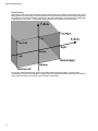
Space Allocations
www.ShipConstructor.com
© Copyright 2011 ShipConstructor Software Inc. – Jun. 16, 11
ShipConstructor 2012 Space Allocations
Published 2011-06-16
Copyright
Copyright © 2011 ShipConstructor Software Inc.
Information in this ShipConstructor manual is the property of ShipConstructor Software Inc. No part of it can be reproduced, translated,
resold, rented, adapted, modified, stored in a retrieval system or transmitted in any form or by any means, in whole or in part. All Rights
Reserved.
Trademarks
ShipConstructor
AutoMagic
SmartParts
Database Driven Relational Object Model
DDROM
Are all registered trademarks of ShipConstructor Software Inc.
ShipConstructor Software Inc.
Suite 304
3960 Quadra Street
Victoria, BC
Canada V8X 4A3
Toll Free:
Phone:
Fax:
1-888-210-7420
1-250-479-3638
1-250-479-0868
Information:
Support:
Sales:
[email protected]
[email protected]
[email protected]
Website:
www.ShipConstructor.com
SHIPCONSTRUCTOR LICENSE AGREEMENT
BEFORE PROCEEDING WITH THE INSTALLATION, YOU MUST ACCEPT THE TERMS OF THIS
AGREEMENT. INDICATE YOUR ACCEPTANCE OR REJECTION OF THIS AGREEMENT BY CLICKING
ON THE APPROPRIATE BUTTON. IF YOU CLICK ON “REJECT,” INSTALLATION WILL ABORT.
License Grant. ShipConstructor Software Inc., #304 – 3960 Quadra Street, Victoria, B.C. Canada, V8X 4A3 (“SSI”) grants
to the person accepting this Agreement (the “Licensee”) a non-exclusive, non-transferable right to use (the “License”)
in object code form those program modules, application programming interface (“API”), any other materials provided
by SSI under this Agreement, and all upgrades, revisions, fixes, updates or enhancements to any of the foregoing
(“Licensed Materials”) specified in the Licensee’s purchase order or request (“Invoice) solely on the software and
hardware listed in the Licensed Materials manual (“System Configuration”).
Academic Institutions/Trial Versions.
A. In the event that the Licensee qualifies as an academic institution user in accordance with SSI’s
specifications (an “Academic Licensee”), the Academic Licensee and its faculty, employees and students may
use the Licensed Materials for the singular purpose of either teaching, training users or undertaking research
provided that the Licensed Materials, and all copies of the Licensed Materials, remain at all times at the
Academic Licensee’s premises and the Licensed Materials are used for no other purpose than that set forth
above. The above restrictions are in addition to the restrictions on use set out in Section 5 below.
B. In the event that the Licensee receives a trial version of the Licensed Materials for evaluation purposes, the
terms and conditions of this Agreement, excluding Sections 15-19, shall continue to apply subject to the
following provisions:
the License pursuant to Section 1 above shall terminate at the end of the specified trial period;
the Licensee shall return the Hardware Key to SSI immediately upon expiry of the specified trial period and in
any event within 28 days of the expiry of the specified trial period;
in the event that the Licensee does not return the Hardware Key in accordance with Section 2B.(b) above, SSI
shall be entitled to invoice the Licensee for and the Licensee shall pay for the costs of the Hardware Key
plus all shipping and handling expenses and SSI administrative charges; and
in the event that the Licensee elects to and does acquire a License, the terms and conditions of this Agreement,
excluding Section 2B herein, shall continue on and apply.
Ownership. All rights, title and interests in and to the Licensed Materials and related documentation shall remain the
sole property of SSI. Licensee shall not remove or alter any proprietary rights notices on the Licensed Materials and
the documentation, and shall reproduce such notices on any copies that it makes. Licensee shall be liable for the
security of the Licensed Materials and the documentation in its possession.
Expertise Required. Licensee is responsible for evaluating whether the Licensed Materials meets Licensee’s
requirements, and for operating the Licensed Materials and the results obtained. The Licensed Materials are
intended for ship modeling and construction purposes only, and must be used by a person who has expertise and
knowledge in this field. The Licensed Materials requires independent confirmation of the reliability and accuracy of
all designs, drawings and other Licensed Materials output. An SSI representative may be made available under a
separate consulting agreement, as the Licensee’s request to provide training and consultation on the operation or
integration of licensed materials.
Limitations on Use.
Licensee shall:
(a)
not make more copies of the Licensed Materials than are necessary for the Licensee’s installation of
the Licensed Materials and shall only create backup copies for archival or emergency restart purposes;
(b)
maintain a log of the number of and location of all originals and copies of the Licensed Materials;
(c)
include SSI’s copyright, trademark and proprietary notices on any complete or partial copies of the
Licensed Materials in the same form and location as the notice on any original work;
(d)
not attempt to defeat any copy protection;
(e)
not modify, any documentation, including any user manuals;
(f)
not modify, translate, reverse engineer, decompile or disassemble the Licensed Materials;
(g)
not sublicense, transfer, assign, sell, loan, rent or lease the Licensed Materials other than as permitted
in this Agreement;
(h)
use the Licensed Materials for its own internal use only;
(i)
not permit any third party to use the Licensed Materials; and
(j)
thoroughly test any and all custom interfaces in accordance with general engineering principles.
6.
Delivery and Installation. All Licensed Materials will be delivered in an electronic format by media or method as SSI
may elect and will be sent to the Licensee’s designated email address or shipping address as specified in the
Invoice. Licensee agrees to be responsible for installation of the Licensed Materials.
7.
Term of License. The License term commences on the delivery of the Licensed Materials to the Licensee, and,
subject to Section 2B above, is either perpetual if so requested on the Order, or on a month to month rental or
lease basis. If Licensee chooses a lease option the license converts to a perpetual term on Licensee’s payment
of the balance of the perpetual License fee (prior monthly payments receiving 80% credit). All Licenses are
subject to termination in accordance with this Agreement.
8.
System Configuration. Operation of the Licensed Materials requires use of the specified System Configuration, which
Licensee shall acquire and implement. SSI shall not be responsible for any operational problems caused by the
System Configuration.
9.
Hardware Keys. Licensed Materials use requires “Hardware Keys” supplied by SSI, which can be used only at the
site(s) authorized by SSI. In the event of a failure of the Licensee’s System Configuration, the Licensee may
upon advising SSI use the Hardware Keys and Licensed Materials on another system and/or location.
10. License Fees. Licensee shall pay to SSI the License fees applicable for the Licensed Materials as set out in and in
accordance with SSI’s Invoice.
11. Services. Support services after the Warranty Period (as defined in Section 15 below) are provided by SSI under the
terms of the SSI Subscription Agreement. Installation, consulting, training and implementation services, if
requested by the Licensee, shall be provided by separate agreement and at an additional charge.
12. Taxes. All amounts payable by Licensee to SSI are exclusive of all commodity taxes, including but not limited to
applicable sales, use, value added, custom duties, excise taxes and other similar government charges, all of
which will be paid by Licensee. If Licensee is required by law to withhold any taxes, then Licensee shall pay SSI
a gross amount of money such that the net amount received by SSI after deducting or withholding the required
taxes is equal to the amount of the fee originally charged by SSI.
13. Interest Charges. If any amount payable under this Agreement is not paid within 30 days of becoming due, SSI shall
have the right to impose a charge of 2% per month (24% annually) on the unpaid balance of the amount, from
the due date until the date of receipt of all amounts in arrears including interest.
14. Purchase Orders. Any purchase order (an “Order”) delivered by Licensee shall at all times be deemed to incorporate
this Agreement by reference and shall be subject to the applicable provisions of this Agreement. Any provisions
of an Order shall not apply and shall not be binding upon SSI unless they relate to information which was
requested by SSI. In the event of a conflict or an inconsistency between the provisions of an Order and the
terms and conditions of this Agreement, this Agreement shall govern and supersede to the extent of such
conflict or inconsistency.
15. Limited Warranty. SSI warrants that during a period of 90 days from the date of delivery of the Licensed Materials to
Licensee (the “Warranty Period”), the Licensed Materials will perform substantially in accordance with the
Licensed Materials documentation specifications, when used in accordance with this Agreement on a properly
operating System Configuration. SSI’s sole obligation under this Warranty, and Licensee’s exclusive remedy,
shall be to use reasonable commercial efforts to correct Errors (a bug, defect or other problem incurred by a
user in operating the Software that prevents the Software from performing in a manner consistent with the
applicable specifications set out in the User Manual) that the Licensee identifies to SSI through fixes or
workarounds free of charge. If SSI determines that it is unable to make the Licensed Materials perform substantially
as warranted, Licensee may terminate the License and receive a refund of a portion of the License Fees paid to date.
16. WARRANTY EXCLUSIONS. THE LIMITED WARRANTY CONTAINED IN SECTION 15 IS IN LIEU OF ALL OTHER
WARRANTIES, EXPRESS OR IMPLIED. ALL OTHER CONDITIONS, WARRANTIES, AND REPRESENTATIONS,
EITHER EXPRESS OR IMPLIED, ARE EXCLUDED, INCLUDING BUT NOT LIMITED TO CONDITIONS,
REPRESENTATIONS AND WARRANTIES RELATING TO MERCHANTABILITY AND FITNESS FOR A PARTICULAR
PURPOSE. SSI DOES NOT WARRANT THAT THE LICENSED MATERIALS ARE COMPLETELY ERROR FREE OR THAT ITS
OPERATION WILL BE CONTINUOUS AND UNINTERRUPTED.
17. Maintenance Services. Licensee may elect, at the expiry of the Warranty Period, to obtain maintenance, support and
upgrade services from SSI in accordance with and subject to the terms of SSI’s standard Subscription
Agreement.
18. Loss of Data. SSI shall not be responsible for any loss of or damage to files or data caused by the Licensed
Materials, or be required to restore or rebuild files or data. Licensee shall implementing adequate backup
procedures to avoid any loss of files and data.
19. Modifications.
SSI may, from time to time, provide the Licensee with revisions to the Licensed Materials (the
“Revised Licensed Materials”). The Licensee shall test any external applications using the revised API before
implementing the new version. While it is SSI’s intention that the Revised Licensed Materials shall be backwardcompatible with the immediately prior version of the Licensed Materials, SSI does not guarantee or warrant that
this shall be so, and SSI shall have no liability whatsoever to the Licensee for any failure of the Revised Licensed
Materials to be backward compatible with any prior version of the Licensed Materials. Modifications requested
by the Licensee shall be subject to prior written agreement as to scope and fees payable. Ownership of all
Licensed Materials modifications shall vest in SSI. SSI does not warrant, guarantee or otherwise commit to
supporting Licensed Materials that has been superseded by Revised Licensed Materials.
20. Confidential Information. Each party will not use the confidential information of the other party for any purpose
except for the purpose described in this Agreement, and shall not disclose it to any other person except on a
confidential basis to its employees and representatives who have a need-to-know the confidential information for
such purposes. This Section 23 shall not apply to confidential information which (a) is or has become readily
available to the public in the same form other than by an act or omission of the receiving party, (b) was lawfully
obtained in the same form by the receiving party from a third party not under an obligation of confidence to the
disclosing party, (c) was in the receiving party’s possession in the same and material form prior to its receipt
from the disclosing party and did not otherwise originate from the disclosing party, or (d) is required to be
disclosed by operation of law.
21. Termination. This Agreement may be terminated by either party, immediately by written notice, if the other party
commits a breach of any material provision of this Agreement, including a failure to make payment when due,
and fails to correct or rectify such breach within 30 days of receipt of the notice requesting it to do so. SSI shall
be entitled to place time-lock devices and other disabling features in the Licensed Materials that become
effective in the event that the Licensee has failed to comply with its payment obligations hereunder and as set
out in SSI Invoices.
22. Effect of Termination. Upon termination of this Agreement Licensee shall immediately cease using the Licensed
Materials, and within 14 days of termination return all Hardware Keys to SSI.
23. CONSEQUENTIAL DAMAGES. IN NO EVENT SHALL SSI BE LIABLE FOR ANY LOSS OF DATA OR PROFITS, ECONOMIC
LOSS OR SPECIAL, INDIRECT, INCIDENTAL, CONSEQUENTIAL OR PUNITIVE DAMAGES WITH RESPECT TO THIS
AGREEMENT OR THE LICENSED MATERIALS, HOWEVER CAUSED, EVEN IF SSI HAD OR SHOULD HAVE HAD ANY
KNOWLEDGE OF THE POSSIBILITY OF SUCH DAMAGES.
24. DAMAGES LIMITATION. THE MAXIMUM LIABILITY OF SSI FOR ALL CLAIMS AND DAMAGES OF ANY KIND, WHETHER
FOR FUNDAMENTAL BREACH OR ANY OTHER CAUSE UNDER THIS AGREEMENT, SHALL BE LIMITED IN THE
AGGREGATE TO THE TOTAL OF ALL FEES PAID BY LICENSEE.
25. LIMITATION OF NON-APPLICABILITY. IN SOME JURISDICTIONS THE EXCLUSION OR LIMITATION OF WARRANTIES OR
LIABILITY MAY NOT BE APPLICABLE, AND IN SUCH JURISDICTIONS SSI HEREBY LIMITS ITS LIABILITY TO THE
FULLEST EXTENT PERMITTED BY LAW.
26. Applicable Law. This Agreement shall be subject to and construed in accordance with the laws of the Province of
British Columbia, Canada, excluding its conflict of laws rules and the application of the UN Convention on
Contracts for the International Sale of Goods.
27. References. SSI shall be allowed to incorporate Licensee’s name in SSI’s customer reference list and to use it for
marketing.
28. Dispute. If any dispute arises under this Agreement, a good faith attempt to resolve the dispute will be made by
senior management of both parties at a mutually agreeable site and time. If the parties are unable to reach
agreement within 30 days after a request for such meeting, the dispute shall be referred to arbitration in
English, before one arbitrator in Victoria, British Columbia, Canada, in accordance with the Commercial
Arbitration Act of the British Columbia.
29. Entire Agreement. This Agreement contains the entire agreement between the parties and shall supersede all prior
discussions and agreements between the parties regarding its subject matter.
30. Amendment. Any amendment of this Agreement must be in writing and signed by duly authorized representatives of
the parties.
31. Waiver. The waiver by any party of a breach by the other party of this Agreement shall not be construed as a waiver
by such party of any succeeding breach by the other party of the same or another provision.
32. Assignments. Licensee may not assign or transfer the License or Licensee’s rights or obligations under this
Agreement without SSI’s prior written consent, and any such assignment or transfer without consent shall be
null and void. A transfer of all or substantially all of the voting stock of the Licensee shall constitute a transfer
for these purposes and shall be subject to SSI’s prior written consent.
33. Successors and Assigns. This Agreement will bind and enure to the benefit of the parties and their respective
successors and permitted assigns.
34. Severability. In the event that any provision of this Agreement is declared invalid, illegal or unenforceable by a court
having jurisdiction, then the remaining provisions shall continue in full force and effect.
35. Force Majeure. Except as related to Licensee’s obligation to make payments to SSI, neither party shall be liable for
delays or non-performance if such delays or non-performance are beyond such party's reasonable control. A
delayed party shall promptly notify the other party in writing stating the cause of the delay and its expected
duration and shall use commercially reasonable efforts to remedy a delay or non-performance as soon as
reasonably possible.
36. Survival. The provisions of Sections 0, 5, 10, 12, 13, 16 and 18-28 shall survive the expiry or termination of this
Agreement.
37. Language. It is the express will of the parties that this Agreement and related documents have been prepared in
English. C’est la volonté expresse des parties que la présente Convention ainsi que les documents qui s’y
rattachent soient rédiges en anglais.
#363338
28/05/2010
Contents
Contents
SHIPCONSTRUCTOR LICENSE AGREEMENT ......................................................................................................................... ii
SPACE ALLOCATION Modeling
1
SPACE ALLOCATION Drawings........................................................................................................................... 1
Create a SPACE ALLOCATION Drawing .................................................................................................................................1
Upon opening a model drawing..............................................................................................................................................1
Set Up SPACE ALLOCATION Groups .................................................................................................................. 1
Create a Group ..........................................................................................................................................................................1
Modify the Properties of a Group ...........................................................................................................................................2
Delete a Group ..........................................................................................................................................................................2
Set the Current Group ..............................................................................................................................................................3
Change the Group for existing Space Allocations ...............................................................................................................3
Checking In/Out Space Allocations................................................................................................................... 3
Space Allocation Manager.................................................................................................................................. 3
Load Strategies.........................................................................................................................................................................3
Creating vs. Loading a Load Strategy....................................................................................................................................4
Creating Space Allocations................................................................................................................................. 4
Straight space allocation.........................................................................................................................................................5
Bent space allocation...............................................................................................................................................................6
Fittings........................................................................................................................................................................................7
Routing Options ..................................................................................................................................................................... 10
Creating Connections While Routing In End Mode........................................................................................................... 11
Offset Routing ........................................................................................................................................................................ 12
Object Snaps........................................................................................................................................................................... 13
Custom Object Snaps............................................................................................................................................................ 14
Modify space allocations...................................................................................................................................16
Anchor a space allocation.................................................................................................................................................... 16
Unanchor a space allocation................................................................................................................................................ 16
Grip-points............................................................................................................................................................................... 17
Toggle Transform Mode........................................................................................................................................................ 17
Resizing a space allocation using grip points ................................................................................................................... 19
Resize Connected Parts........................................................................................................................................................ 20
Symmetrical vs. Asymmetrical Resize ............................................................................................................................... 20
Break a space allocation...................................................................................................................................................... 21
Connect space allocations ................................................................................................................................................... 22
OPM ......................................................................................................................................................................22
Activate UCS from Parts....................................................................................................................................23
i
Contents
Index
ii
27
SPACE ALLOCATION Modeling
SPACE ALLOCATION Modeling
This section of the manual explains how to use the tools provided in the SPACE ALLOCATION module to create and load
Space Allocations in any type of model drawing.
SPACE ALLOCATION Drawings
Create a SPACE ALLOCATION Drawing
Before modeling an SPACE ALLOCATION drawing, you must create one
To create an SPACE ALLOCATION drawing
1.
Choose ShipConstructor > Navigator to open Navigator.
2.
Select SPACE ALLOCATION in the component list.
3.
Select the SPACE ALLOCATION folder in the drawing list.
4.
Click New SPACE ALLOCATION.
The New Drawing window appears.
5.
Enter a File name for the drawing.
Note: To open the new drawing, check the Open new drawing check box.
6.
Click OK.
Upon opening a model drawing
When opening any type of model drawing containing space allocations, if connected to the database, synchronization
occurs between the drawing and the database. All space allocations in the drawing must exist within a load strategy
attached to the drawing. If parts have been added ore removed from an attached load strategy they will be added or
removed from the drawing.
Set Up SPACE ALLOCATION Groups
A SPACE ALLOCATION group is a collection of SPACE ALLOCATION parts that together fulfill a specific purpose (for
example, the heating group or the ventilation group). Each group can have any number of subgroups. Before you can
begin modeling SPACE ALLOCATION, you must set up a group.
Create a Group
To create a group
1.
Open Navigator ‘_SCCATALOG’
2.
Choose Space Allocation > Group to open the Group Manager.
1
SPACE ALLOCATION Modeling
3.
Optionally choose a group that you want the new group to be a child of.
4.
Click New.
5.
Enter a name for the new group.
6.
Set the group color.
7.
Click OK to save and close the Group Manager.
Modify the Properties of a Group
To modify the properties of a group
1.
Open Navigator ‘_SCCATALOG’
2.
Choose Space Allocation > Group to open the Group Manager.
3.
Select the Group to modify.
4.
Modify the group name or color.
5.
Click OK to save and close the Group Manager.
Delete a Group
To delete a Group
Note: You cannot delete a group if space allocations have been assigned to that group.
2
1.
Open Navigator ‘_SCCATALOG’
2.
Choose Space Allocation > Group to open the Group Manager.
3.
Select the group you want to delete.
4.
Click Delete.
5.
Click OK to close the Group Manager.
SPACE ALLOCATION Modeling
Set the Current Group
To set the current Group
1.
If no space allocations exist within a drawing the first time one is created the Group Selection Dialog will appear.
2.
Select the group you want to make current.
3.
Click OK to close the Group Selection Dialog.
-OR-
1.
Choose SC SPACE ALLOCATION > Change Space Allocation Group.
2.
The Group Selection Dialog will appear.
3.
Select the group you want to make current.
4.
Click OK to close the Group Selection Dialog.
Change the Group for existing Space Allocations
To change the Group
1.
Type the command SCSPALLCHANGEGROUP
2.
Optionally select SPACE ALLOCATION parts from the current drawing or press enter to continue.
5.
The Group Selection Dialog will appear.
6.
Select the group you want to make current.
3.
Click OK to close the Group Selection Dialog.
4.
The current Group is now set, and any space allocations selected will be assigned to that group.
Checking In/Out Space Allocations
To edit any properties of an existing space allocation it must be checked to a drawing. Newly created space allocations
are automatically checked out to the drawing they were created in. On close of a drawing any space allocations checked
out to it will be checked back in.
To check out a space allocation
1.
Right click on a space allocation and choose the ‘Check In’ or ‘Check Out’ options.
2.
Use the ‘SCSPALLCHECKIN’ or ‘SCSPALLCHECKOUT’ commands.
3.
In the space allocation manager select a space allocation and use the ‘Check In’ or ‘Check Out’ buttons.
Space Allocation Manager
Load Strategies
All space allocations are organized by group. To bring in a subset of space allocations into a drawing you have the option
of attaching ‘Load Strategies’ to a drawing. There exist three types of load strategy that a drawing can contain.
1. ‘By Drawing’ Using a by drawing load strategy will bring in all space allocations attached to the chosen drawing.
2. ‘By Group’ A by group load strategy loads all space allocations within a specific group.
3. ‘By Volume’ By volume load strategies do a bounds check on all space allocations that exist within a project and bring
in the ones that fall within a user defined area.
The first time a space allocation is created within a model drawing a ‘By Group’ load strategy for the chosen group is
automatically added to the drawing.
3
SPACE ALLOCATION Modeling
To load existing space allocations into a model drawing a load strategy must be attached to the drawing.
The ‘Space Allocation Manager’ must be opened to attach a load strategy to a drawing.
To open the Space Allocation Manager
Use the menu ‘SC SPACE ALLOCATION > Space Allocation Manager’ or the ‘SCSPALLMANAGER’ command
Creating vs. Loading a Load Strategy
Using the `Create` button to bring a load strategy into the drawing will bring space allocations into the drawing but will
not check any of them out. The ‘Load’ button will attempt to check out any space allocations it brings into the drawing.
Creating Space Allocations
You create a SPACE ALLOCATION model by inserting space allocations into model drawings.
4
SPACE ALLOCATION Modeling
Routing a space allocation typically involves selecting a group and then providing geometric input that determines where
the space allocation is located and how it is oriented. You will provide geometric input by clicking points in the model and
using the command line options.
Later when placing another space allocation, any jigging option changes made previously will be used. Command line
options are provided to make it easier to modify some geometric properties of space allocations.
Straight space allocation
To route a straight space allocation, you will select a group and then provide two points indicating the start and end
points of the space allocation.
To insert a straight space allocation
1.
Choose SC SPACE ALLOCATION > Straight.
A straight space allocation appears with the first end at the cursor. Information about the space allocation is shown
on the command line.
2.
You are prompted to pick the start point of the space allocation or choose an option:
Please pick point : or [Stock/Next end <1>/XOffset/YOffset/Choose offset <0,0>
/Rotate/sAddle/Insulation]:
If desired, choose one of the available options (see Routing Options (page 10) for options not listed here):
•
Next end – Switches which end of the space allocation will be placed at the picked point.
•
Rotate – Rotates the space allocation around its own centerline (the NavAid is not affected).
3.
Click anywhere in the model to select the start point of the space allocation. You can connect to an existing
unconnected space allocation end by clicking on its end point, or anywhere along its centerline. The NavAid appears
at the selected point and the end point of the space allocation you are placing is anchored there.
4.
You are prompted to pick the second point or choose an option:
5
SPACE ALLOCATION Modeling
Please pick point : or
SNap<on>]:
[Forward/Aft/Port/Starboard/Up/Down/plaNE/XRotate/YRotate/ZRotate/
See Routing Options (page 10) for explanation of the available options.
Note: If you created a connection to another space allocation by clicking on a free end or by creating a saddle,
several of the options shown above do not apply (for example, the direction options) and are not available.
5.
Click anywhere in the model to select the end point of the space allocation. If you connected the space allocation in
step 3, any point you pick (including OSNAPs) is projected onto the axis of the end you connected to.
Bent space allocation
To insert a bent space allocation by picking points
To route a bent space allocation with this method, you will select a sequence of points that form the path to which the
segments of the bent space allocation will be aligned.
After jigging is over, the bent space allocation is split into its composite straights and arcs
1.
Choose SC SPACE ALLOCATION > Bent.
The first segment of a bent space allocation appears with the first end at the cursor. Information about the space
allocation is shown on the command line.
2.
You are prompted to pick the start point of the bent space allocation or choose an option:
Please pick point : or [Stock/Next end <1>/XOffset/YOffset/Choose offset <0,0>/Toggle
mitered <rounded>/Rotate/sAddle/Insulation]:
If desired, choose one of the available options (see Routing Options (page 10) for options not listed here):
3.
•
Next end – Switches which end of the bent space allocation will be placed at the picked point.
•
Toggle mitered – Switch between rounded corners and mitered corners. The current setting is shown in <angle
brackets>. If you switch to mitered corners, you must specify the number of miter segments per corner.
•
Rotate – Rotates the space allocation around its own centerline (the NavAid is not affected).
Click anywhere in the model to select the start point of the space allocation.
You may also connect to an existing unconnected space allocation end by clicking on its end point, or anywhere
along its centerline. The NavAid appears at the selected point and the end point of the space allocation you are
placing is anchored there.
4.
6
You are prompted to pick the second point or choose an option:
SPACE ALLOCATION Modeling
Please pick point : or
SNap<on>]:
[Forward/Aft/Port/Starboard/Up/Down/plaNE/XRotate/YRotate/ZRotate/
See Routing Options (page 10) for explanation of the available options.
Note: If you created a connection to another space allocation by clicking on a free end or by creating a saddle
connection, several of the options shown above do not apply (for example, the direction options) and will not be
available.
5.
Click anywhere in the model to select the second point of the space allocation. If you connected the space allocation
in step 3, any point you pick (including OSNAPs) is projected onto the axis of the end you connected to.
To choose a point along the axis of an existing end, click the existing end. Your next input point will be restricted to
the axis.
The NavAid appears at the selected point and the first space allocation bend appears.
6.
To create a bend in the space allocation, repeat Steps 4 and 5 for the bend points. Note that he command prompt
has extra options for further points :
Please pick point : or [XOffset/YOffset/Choose offset <0,0>/Radius<200>/World plane/Initial
plane/paRT plane/Align to
part/Forward/Aft/Port/Starboard/Up/Down/plaNE/XRotate/YRotate/ZRotate/ SNap<on>]:
If desired, choose one of the available options (see Routing Options (page 10) for options not listed here):
•
Radius – Changes the corner radius of the bend being manipulated. The current radius is shown in <angle
brackets>.
•
World plane – Aligns the NavAid to the world coordinates.
•
Initial plane – Aligns the NavAid to the UCS that was active when the command started.
•
Part plane – Aligns the NavAid to the plane of the most recently placed segment of bent.
•
Align to part – Aligns the X-Axis of the NavAid to the axis of the most recently placed segment of the bent.
•
Unlock – If you clicked on an existing end in step 5 to restrict your picked point to the axis of that end, this
option will remove the restriction.
To finish a bent space allocation, press Enter.
Fittings
There are two means by which fittings can be placed. End Mode involves placing a fitting by specifying a location and
orientation for one of its ends. Intersection Mode lets you place a fitting where two runs of space allocation will meet.
End Mode
When placing a fitting in end mode, you initially only need to consider which end you are placing (or connecting to
another space allocation).
To insert a fitting in end mode
1.
Choose the desired fitting you want to insert from the SC SPACE ALLOCATION menu. The fitting appears at the cursor
and information about it is shown on the command line.
2.
You are prompted to pick the first point or choose an option from the end mode command line:
Please pick the first point of the end axis : or [Next end <1>/inTersection
mode/XOffset/YOffset/Choose offset <0,0>/sAddle/Insulation]:
If desired, choose one of the available options (see Routing Options (page 10) for options not listed here):
3.
•
Next end – Switches which end of the fitting will be placed at the picked point.
•
Intersection Mode – Switches the routing interface to intersection mode (see Intersection Mode (page 8)).
Click anywhere in the model to select the start point of the fitting. You can connect to an existing unconnected space
allocation end by clicking on its end point, indicated by an arrow (see Creating Connections While Routing In End
Mode (page 11)). The NavAid appears at the selected point and the end point of the fitting you are placing is
anchored there.
7
SPACE ALLOCATION Modeling
4.
If you connected the fitting to another space allocation, continue from Step 6. Otherwise, you are prompted to pick a
point indicating the direction of the end you just placed or choose an option:
Please pick the second point of the end axis : or
[plaNE/XRotate/YRotate/ZRotate/SNap<on>]:
See Routing Options (page 10) for explanation of the available options.
5.
Click anywhere in the model to specify the direction of the current end’s axis (i.e. the end axis will be parallel to the
line formed by this point and the point that you clicked in Step 3). The fitting is now restricted to rotation about this
axis.
Specifying the location and normal of End 1.
6.
You are prompted to pick a point indicating the direction of an orienting end of the fitting or to choose an option:
Please pick a point indicating a rotation about the defined end axis : or [Next end for
orientation <1>/Forward/Aft/Port/Starboard/Up/Down/DEck align/FRame align/Long align/ALign to
WCS/ZRotate/SNap<on>]:
Depending which end you placed in Step 3, not all ends will be available as an orienting end while cycling through
ends with Next end for orientation. For example, if you placed a tee by one end of its trunk, the other end of the trunk
is not useful to orient the tee with, but the branch is.
If desired, choose one of the available options (see Routing Options (page 10) for options not listed here):
•
7.
Next end for orientation – Switches the end governing the orientation of the fitting.
Click anywhere in the model to specify the direction of the orienting end.
Intersection mode
You will typically use intersection mode to place a fitting (or possibly multiple elbows) where two non-parallel space
allocation runs will meet (that is, where their centerlines will intersect).
If you are placing the fitting before the space allocation runs on either side exist, you will directly specify the location of
the intersection point and then set the orientation of the fitting.
8
SPACE ALLOCATION Modeling
If one of the other space allocation runs exists already, you will align one end of your fitting with that run and then specify
how far from that existing run the fitting is placed. If both of the other runs exist already, you will align one end of your
fitting to one space allocation run and a second end of your fitting to the other run.
To insert a fitting in intersection mode when the connecting runs do not exist yet
1.
Choose the desired fitting you want to insert from the SC SPACE ALLOCATION menu. The fitting appears at the cursor
and information about it is shown on the command line.
2.
If end mode is active, switch to intersection mode (see step 2 of End Mode (page 7)); otherwise continue with Step 3.
3.
You are prompted to pick the location of the intersection point or choose an option:
Please pick the first point of the end axis : or
mode/Insulation]:
[Next end <1>/neXt point <1>/End
If desired, choose one of the available options (see Routing Options (page 10) for options not listed here):
•
Next end – Switches which end of the fitting will be aligned to the axis formed by the first two points you will
choose in steps 4 and 6.
•
Next point – Switches which intersection point of the fitting you want to place in step 4. You may not see this
option if a fitting has only one intersection point (e.g. a non-offset elbow or basic tee).
•
End mode – Switches the routing interface to end mode (see End Mode (page 7)).
4.
Click anywhere in the model (except a free end) to specify a location for the current intersection point.
5.
You are prompted to pick a second point defining the axis to which the current end of the fitting will be aligned or to
choose an option.
Please pick the second point of the end axis : or
ZRotate/SNap<on>]:
[orieNting end <1>/plaNE/XRotate/YRotate/
If desired, choose one of the available options (see Routing Options (page 10) for options not listed here):
•
Orienting end – Switches which end of the fitting will be aligned to the axis formed by the point you picked in
6.
step 4 and the point you will pick in step 7.
Click anywhere in the model to specify the direction of the current end’s axis (i.e. the end axis will be parallel to the
line formed by this point and the point that you clicked in Step 3). The fitting is now restricted to rotation about this
axis.
7.
You are prompted to pick a point indicating the direction of an orienting end of the fitting or to choose an option:
Please pick a point indicating a rotation about the defined end axis : or [Next end for
orientation <1>/Forward/Aft/Port/Starboard/Up/Down/DEck align/FRame align/Long align/ALign to
WCS/ZRotate/SNap<on>]:
Depending which end you placed in Step 3, not all ends will be available as an orienting end while cycling through
ends with Next end for orientation. For example, if you placed a tee by one end of its trunk, the other end of the trunk
is not useful to orient the tee with, but the branch is.
If desired, choose one of the available options (see Routing Options (page 10) for options not listed here):
•
8.
Next end for orientation – Switches the end governing the orientation of the fitting.
Click anywhere in the model to specify the direction of the orienting end.
To insert a fitting in intersection mode when one or both of the connecting runs already exist
1.
Choose the desired fitting you want to insert from the SC SPACE ALLOCATION menu. The fitting appears at the cursor
and information about it is shown on the command line.
2.
If end mode is active, switch to intersection mode (see step 2 of End Mode (page 7)); otherwise continue with Step 3.
3.
You are prompted to pick the first point or choose an option from the Intersection Mode line:
Please pick the first point of the end axis : or
mode/Insulation]:
[Next end <1>/neXt point <1>/End
If desired, choose one of the available options (see Routing Options (page 10) for options not listed here):
•
•
Next end – Switches which end of the fitting will be aligned to the axis of the end you will select in step 4.
Next point – You will be picking an existing end in step 4 (and not directly placing an intersection point); this
option is not relevant to this routing method.
9
SPACE ALLOCATION Modeling
•
End mode – Switches the routing interface to end mode (see End Mode (page 7)).
4.
Click any free end in the model to indicate the end axis you want to place the fitting on. The fitting is now restricted
such that its end is aligned with the end you clicked on.
5.
You are prompted to pick a point indicating how far along the axis (chosen in step 4) the fitting should be placed.
Please pick a point indicating distance from the existing end : or
<4>]:
[Next end for orientation
If more than one end is available for orientation, you can switch the end:
•
6.
Next end for orientation – Switches the end governing how far along the chosen end axis the fitting is placed.
Click anywhere in the model to fix the distance between the fitting and the end you clicked in step 4.
If the second run you are looking to connect to already exists, you may click on its free end. Should the angle of the
fitting differ from the angle between the two ends, a warning is printed. If you are routing an elbow, you may be given
additional options to deal with the differing angle.
If you clicked an existing free end you are finished; otherwise the fitting’s distance from the end you clicked in step 4
is fixed; continue with step 7.
7.
You are prompted to pick a point indicating the direction of an orienting end of the fitting or to choose an option:
Please pick a point indicating a rotation about the defined end axis : or [Next end for
orientation <1>/Forward/Aft/Port/Starboard/Up/Down /DEck align/FRame align/Long align/ALign
to WCS/ZRotate/SNap<on>]:
Depending which end you placed in Step 3, not all ends will be available as an orienting end while cycling through
ends with Next end for orientation. For example, if you placed a tee by one end of its trunk, the other end of the trunk
is not useful to orient the tee with, but the branch is.
If desired, choose one of the available options (see Routing Options (page 10) for options not listed here):
•
8.
Next end for orientation – Switches the end governing the orientation of the fitting.
Click anywhere in the model to specify the direction of the orienting end.
Routing Options
Several routing options are available in many different routing cases and serve more or less the same use in each case.
To use the options, type their shortcuts (the letters that are capitalized when the options are displayed on the command
line). Descriptions of each follow.
NavAid specific options
The following options affect the NavAid’s behavior or orientation.
•
Snap – Toggles snapping of picked points to fixed angles (shown as spikes on the NavAid). The current setting is
displayed in the command line in <angle brackets>.
•
Plane – Changes the NavAid plane to a perpendicular one (the plane formed by the Z and X axes of the current UCS);
effectively cycles the NavAid plane between the 3 axial planes of the current UCS.
•
XRotate/YRotate/ZRotate – These options rotate the NavAid (or equivalently, the current UCS) about the respective
axis according to the right-hand rule.
World coordinate alignment options
The following options are often available at times when you are prompted to pick a point specifying a direction or
rotation. They are a convenient way to get diagonally oriented runs pointing back along world-coordinate axes and planes.
•
Forward/Aft/Port/Starboard/Up/Down – These options automatically provide input equivalent to a point in the
respective direction (or as close as possible to that direction, depending on the situation).
If you are routing a trimmable elbow, it is often the case that trimming it will allow alignment to directions not
otherwise possible. In these cases, options for all possible directions will be available; choosing one that requires
trimming will result in a prompt asking if you wish to trim the elbow to allow the alignment.
•
10
Deck align/Frame align/Long align – These options will automatically provide you with an alignment such that the
end you are orienting points in a direction lying parallel to the ship’s decks, frames, or longitudinal bulkheads,
respectively. When there are 2 directions that result in the chosen alignment (which is usually the case),
SPACE ALLOCATION Modeling
ShipConstructor will arbitrarily choose one of them and then ask you if you would like to use the other direction
instead.
•
Align to WCS – Aligns the NavAid such that its spikes are directed along world axes (only available in certain cases
when the NavAid already lies in a world plane).
Offset routing options
These options affect your current routing offset (see Offset Routing (page 12)).
•
XOffset/YOffset – Prompts you to type the new X or Y component of the routing offset, respectively.
•
Choose offset – Allows you to choose a routing offset visually; you will type the letter corresponding to one of several
named points on the bounding box of the space allocation’s profile at the current end.
Creating Connections While Routing In End Mode
Connection creation is initiated by clicking an existing free space allocation end when picking the first point or by clicking
anywhere on the centerline.
1.
Click a point to determine the direction, or if you selected an object coordinate system on the header part, enter a
distance along its z-axis. If you clicked on an existing end, skip to step 6.
The branch part and NavAid appear at the selected point. You are prompted to pick a point indicating the direction of
the saddle end.
Please pick point : or [Center-offset<0>/Edge-offset/Flip-offset/Rotate90/World
plane/Initial plane/paRt plane/Align to
part/FOrward/AFt/Port/Starboard/Up/Down/plaNE/XRotate/YRotate/ZRotate/ SNap<on>]:
Optionally, enter one of the keywords:
•
Center-offset – To set an offset between the end axis of the branch part and the centerline of the header part
(the current offset is shown in <angle brackets>), type C (for Center-offset) and press Enter. Type an offset value
and press Enter.
•
Edge-offset – To set an offset between the edge of the branch part’s profile and the edge of the header part’s
profile (the current offset is shown in <angle brackets>), type E (for Edge-offset) and press Enter. Type an offset
value and press Enter. This option is only available when the header part has a consistent profile in the area
local to the saddle end.
•
Flip-offset – To reverse the direction of the current center or edge offset, type FL (for FLip-offset).
•
Rotate90 – To rotate the branch part about its own end axis by 90 degrees, type R (for Rotate90).
•
World plane – To align the NavAid to the world coordinate axes, type W (for World plane) and press Enter.
•
Initial plane – To align the NavAid to the UCS that was current when the command started, type I (for Initial
plane) and press Enter.
•
Part plane – To align the NavAid to the plane the header part lines in and the direction of its centerline closest
to the saddle end, type RT (for paRT plane) and press Enter.
•
Align to part – To rotate the NavAid within its own plane so that its zero angle is aligned with the nearest point
on the header part’s center line, type A (for Align to part) and press Enter.
•
Forward – To set the direction of the orienting end as close as possible to forward, type F (for Forward) and press
Enter.
•
Aft – To set the direction of the orienting end as close as possible to aft, type A (for Aft) and press Enter.
•
Port – To set the direction of the orienting end as close as possible to port, type P (for Port) and press Enter.
•
Starboard – To set the direction of the orienting end as close as possible to starboard, type S (for Starboard) and
press Enter.
•
Up – To set the direction of the orienting end as close as possible to up, type U (for Up) and press Enter.
•
Down – To set the direction of the orienting end as close as possible to down, type D (for Down) and press Enter.
•
Snap – To turn on or off snapping of picked points to fixed angles (the current setting is displayed in the
command line in <angle brackets>), type SN (for SNap) and press Enter.
11
SPACE ALLOCATION Modeling
Offset Routing
Offset routing lets you route a space allocation or fitting by specifying where it is relative to other geometry in the model.
During typical use of offset routing, you specify offset values for a space allocation and then click on Object snap points of
other geometry in the model (for example, structure parts, other space allocations, or construction lines). A routing offset
is specified as an X and Y value in a coordinate Group perpendicular to the centerline of a space allocation.
You can enter values separately for the X and Y offsets with the XOffset and YOffset options or choose an offset
corresponding to a point on the bounding box of a space allocation’s profile with the Choose offset option. An example of
how an offset vector affects the routing of a space allocation is shown below.
12
SPACE ALLOCATION Modeling
space allocation routed with four input points from several line segments with a left offset of 500 (offset vector <-500,0>).
Object Snaps
SPACE ALLOCATION space allocations have several Object snap points that you may find useful when routing space
allocations or transforming existing space allocations (see Multi-Part Transforms (page 19) or Single-Part Transforms
(page 17)). The Object snaps can be enabled or disabled by clicking the OSNAP button on the AutoCAD status bar, by
pressing F3, or by right clicking on the OSNAP button and clicking On or Off. To enable or disable the Object snaps types,
right click on the OSNAP button and click Settings.
Endpoint Object Snaps
AutoCAD Endpoint Object snaps can be found at end points of space allocations and at end points of the subsegments of
a bent space allocation.
Midpoint Object Snaps
AutoCAD Midpoint Object snaps can be found on the midpoint of straight segments of space allocations.
13
SPACE ALLOCATION Modeling
Nearest Object snap
SPACE ALLOCATION space allocations support AutoCAD’s nearest Object snap by snapping points to each space
allocation’s centerline.
Custom Object Snaps
In addition to the supported AutoCAD Object snaps, several custom Object snap types are supported. The custom Object
snaps can be enabled or disabled by clicking the SCON OSNAP button (located beside the OSNAP button on the AutoCAD
status bar), by pressing shift+F3, or by right clicking on the SCON OSNAP button and click On or Off. To enable or disable
the custom Object snaps types, right click on the SCON OSNAP button and click Settings. The custom Object snap
settings will be saved between ShipConstructor sessions.
14
SPACE ALLOCATION Modeling
All End Object Snaps
These are the points in the model where distributed Groups ends exist.
Free End Object Snaps
These are the points in the model where unconnected distributed Groups ends exist (a subset of the points provided by
the EndPoint object snaps).
End Axis Intersections
End axis intersection snaps are points where end axes of a part meet. For branch fittings, you will find these snaps where
the centerline of a branch meets the centerline of the trunk. For an elbow, you will find them where the two end axes
meet (which is the intersection of the tangent lines defined by the centerline and the two end points of the elbow).
15
SPACE ALLOCATION Modeling
Profile Corners Object Snaps
Profile corner snaps are located on distributed Groups ends. These points are the corners of the bounding box of the
profile (see the points labeled Top-Left, Top-Right, Bottom-Left, and Bottom-Right in Offset Routing (page 12)).
Profile Edges Object Snaps
Profile edge snaps are located on distributed Groups ends. These points are the mid-points of the edges of the bounding
box of the profile (see the points labeled Left, Right, Top, and Bottom in Offset Routing (page 12)).
Modify space allocations
Anchor a space allocation
Anchored space allocations do not move when you perform a transform.
To anchor a space allocation
1.
Right click on a part and choose ‘Anchor’
Note: An anchored space allocation will not provide grips when selected.
Unanchor a space allocation
To unanchor space allocations
2.
16
Right click on a part and unselect ‘Anchor’
SPACE ALLOCATION Modeling
Grip-points
Grips are in the same locations regardless of which transform mode you are using, but they behave differently in each
mode.
In single-part transform mode, there are three types of grips: end, corner, and middle grips. End grips are square, corner
grips are round, and center grips are triangular. Their behavior is part-specific (see Single-Part Transforms (page 17)).
In multi-part mode, all grips look and behave similarly.
Toggle Transform Mode
There are two modes in which you can transform existing space allocations. Single-part transform mode lets you make
specialized changes to individual parts. Multi-part transform mode lets you move larger sections of a space allocation
Group simultaneously. You can toggle between single-part and multi-part transform modes.
To toggle the current transform mode
1.
Click the transform mode icon,
, on the transform toolbar.
Single-Part Transforms
Connected parts
If a part with connections is moved the connections will become lengthened and the previously connected parts will be
treated as unattached by the multipart transform engine.
17
SPACE ALLOCATION Modeling
Bent space allocations
The middle grips can be used to translate the entire bent space allocation without changing its geometry.
End and corner grips behave similarly for bent space allocations. The points you initially clicked when creating the bent
space allocation are actually the same points as the end and corner grips. Moving a grip to a different location can be
thought of as moving one of the input points and recreating the bent space allocation. You can only move a grip point so
that the locations of the other grips are not changed.
18
SPACE ALLOCATION Modeling
Multi-Part Transforms
Multi-part transforms let you manipulate large sections of connected space allocations simultaneously. Typical uses of
multi-part transforms are tasks like fine-tuning the location of large sections of a space allocations or adjusting the
location of branches (fittings or saddles).
Experimenting may be the most effective way to familiarize yourself with the behavior of these transforms, but it may
also be helpful to understand some of the logic ShipConstructor uses to help you in cases where a particular transform is
not behaving as you expect it to.
Helpful things to know about multi-part transforms:
•
Parts connected with a lengthened connection will not move.
•
Selecting a grip on a rigid section effectively selects the entire rigid section (that is, selecting more than one grip
point on the same rigid section has no effect).
•
Selecting more than one grip point selects all of the connected space allocation work between the grips. More
specifically, selecting a set of grips is equivalent to selecting all grips points along all possible paths from every
selected grip point to every other selected grip point.
•
Anchored parts will not move. Free ends are treated similarly to anchors and will not move, unless they are part of
the current selection.
•
When multiple grips are dragged, the entire selected section will move by exactly the same amount and in the same
direction. That is, the constraints governing how a set of grip points can move include the constraints imposed by
each individual grip in the selected section.
•
Within the above constraints, the primary goal of the multi-part transform solver is to determine a way to modify the
space allocations so that selected grips are moved as close as possible to where you drag them. The multi-part
transform engine will adjust as much of the space allocations as is necessary to accomplish this goal, which could
mean transforming parts a significant distance away from the selected grips. Anchors are the best way to limit which
portions of the space allocations can be affected.
•
The transform solver’s secondary goal is to optimize the changes that are made to the space allocations so that the
changes to the space allocations are as localized as possible. That is, changes to parts closer to the selected grips
are preferred over changes to parts further away from the grips.
Resizing a space allocation using grip points
•
All space allocations have the option to be drag-resized with grip points. By right clicking on a space allocation you
can toggle the options to show and hide resize grips, to resize space allocations symmetrically and to resize
connected parts
19
SPACE ALLOCATION Modeling
Resize Connected Parts
•
When ‘Resize Connected Parts’ is on parts connected to a part resized with the grip points will also be resized if they
match all of the following conditions:
1. Part is checked out to the current drawing.
2. Unanchored
3. Profile shape is the same as the resized part before resize.
4. Connection length is zero
Symmetrical vs. Asymmetrical Resize
•
20
Dragging a resize grip when symmetrical resize is set keeps the end point in the same position and applies the resize
operation equally to all sides of the space allocation.
SPACE ALLOCATION Modeling
•
When asymmetrical resize is set, the end points of a space allocation are adjusted so that a specific side of a space
allocation can be resized without the other side moving.
Break a space allocation
Straight and bent space allocations support the AutoCAD’s native break command. See AutoCAD documentation for
further information. ShipConstructor registers a command, through LISP, called SCBAP that automatically splits a space
allocation object at a given point leaving two full length pieces.
The SCBAP command also allows for the Spacebar or Enter keys to repeat the command unlike the AutoCAD toolbar
command.
21
SPACE ALLOCATION Modeling
To break space allocations
1.
Run SCBAP command.
2.
Choose point to split space allocation.
Connect space allocations
To connect space allocations
1.
Run the SCSPALLCONNECT command.
2.
Select the first free end, or any part on the centerline to connect.
3.
Select an end to connect to the first selected end. This is the part that will be moved by the multi-part transform
engine to facilitate the desired connection if it is necessary.
OR
3.
If you chose two coincident ends in step 2, choose the part you wish to be moved to make the connection if it is
necessary.
OPM
The Object Properties Manager (OPM) in AutoCAD is a very powerful tool when used with ShipConstructor entities.
Each ShipConstructor entity has properties which can be seen in the OPM, many of which can be modified directly
through the OPM without running separate commands.
22
SPACE ALLOCATION Modeling
In this example, the properties with the white background are the properties which are editable. There are general
properties as well as part-specific properties. User-defined attributes that are assigned to the stock or part can be seen
here. The part user-defined attributes can be edited through the OPM. The ShipConstructor entities have logically
categorized properties according to the specific part’s properties for easy navigation.
Activate UCS from Parts
This is a ShipConstructor Utility function that is accessed through either the SC Utilities > Activate UCS… menu command
or through the Utilities toolbar button
. This utility behaves differently depending on what type of ShipConstructor
parts are selected while using the command.
This document describes the command if you select a Distributed Groups part. For information on this command while
selecting other ShipConstructor parts, please refer to the respective parts’ documentation.
23
SPACE ALLOCATION Modeling
To activate a UCS from a part
1.
Choose SC Utilities > Activate UCS… or Utilities toolbar >
.
The Activate UCS window appears. For more information about the options in this window, please see the Structure
manual.
2.
Click on the Activate from Object button.
3.
Select a Distributed Groups part such as SPACE ALLOCATION.
Note: Xref’d objects and dimensions are also selectable.
The Select UCS Options window appears.
24
SPACE ALLOCATION Modeling
4.
Select the options for the UCS and click OK. See Select UCS Options Reference for more information.
The UCS will now be activated based on the options selected. To see a list of all the UCSs in your drawing, open up the
Activate UCS window again and you should see the UCS that you just created.
25
Index
Index
No index entries found.
27