1
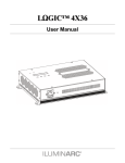
Ilumipod 48 IP Optic RGBW
USER MANUAL
www.ILUMINARC.com
(954) 923-3680
TABLE OF CONTENTS
1. Before You Begin ................................................................................................................................ 3
What is included ....................................................................................................................................... 3
Unpacking Instructions .............................................................................................................................. 3
AC Power ................................................................................................................................................. 3
Safety Instructions .................................................................................................................................... 4
2. Introduction ......................................................................................................................................... 5
Features ................................................................................................................................................... 5
DMX Channel Summary ............................................................................................................................ 6
Product Overview...................................................................................................................................... 8
Dimensions............................................................................................................................................... 9
3. SETUP ............................................................................................................................................... 10
AC Power ............................................................................................................................................... 10
Mounting ................................................................................................................................................ 11
Orientation .............................................................................................................................................. 11
Rigging ................................................................................................................................................... 11
Fixture Linking ........................................................................................................................................ 12
Data Cabling........................................................................................................................................... 12
DMX Data Cable ..................................................................................................................................... 12
Cable Connectors ................................................................................................................................... 12
3-Pin to 5-Pin Conversion Chart .............................................................................................................. 13
Setting up a DMX Serial Data Link ........................................................................................................... 13
Master/Slave Fixture Linking ................................................................................................................... 13
4. Operating Instructions ...................................................................................................................... 14
Control Options ....................................................................................................................................... 14
DMX-512 control without ID address ........................................................................................................ 14
DMX-512 addressing with ID address ...................................................................................................... 14
Setting the DMX address......................................................................................................................... 15
Control Panel Functions .......................................................................................................................... 15
Menu Map .............................................................................................................................................. 16
DMX512 Channel Values ........................................................................................................................ 17
STAG ..................................................................................................................................................... 17
Important Notes about STAG DMX Operation .......................................................................................... 19
Arc.1 ...................................................................................................................................................... 21
Ar1.d ...................................................................................................................................................... 21
Contact Us.............................................................................................................................................. 22
5. Appendix ........................................................................................................................................... 22
DMX Primer ............................................................................................................................................ 22
General Maintenance .............................................................................................................................. 23
Returns Procedure .................................................................................................................................. 23
Claims .................................................................................................................................................... 23
Ilumipod 48 IP Service Maintenance Guide .............................................................................................. 24
Blow-out Diagram. .................................................................................................................................. 25
Technical Specifications .......................................................................................................................... 27
Ilumipod 48 IP Optic RGBW User Manual
2
5/21/2009 11:50 AM
1. BEFORE YOU BEGIN
What is included
1 x Ilumipod 48 IP Optic RGBW
1 x Power cable with plug
1 x IP66 power extension cable
1 x IP66 signal extension cable
1 x DMX input cable adapter
1 x DMX output cable adapter
1 x Warranty Card
1 x User Manual
Unpacking Instructions
Immediately upon receiving a fixture, carefully unpack the carton, check the contents to ensure that
all parts are present, and have been received in good condition. Notify the shipper immediately and
retain packing material for inspection if any parts appear damaged from shipping or the carton itself
shows signs of mishandling. Save the carton and all packing materials. In the event that a fixture
must be returned to the factory, it is important that the fixture be returned in the original factory box
and packing.
AC Power
This fixture has an auto-switching power supply that can accommodate a wide range of input
voltages. The only thing necessary to do before powering on the unit is to make sure the line voltage
you are applying is within the range of accepted voltages. This fixture will accommodate between
100V and 240V AC 50/60 Hz. All fixtures must be powered directly off a switched circuit and cannot
be run off a rheostat (variable resistor) or dimmer circuit, even if the rheostat or dimmer channel is
used solely for a 0% to 100% switch.
Ilumipod 48 IP Optic RGBW User Manual
3
5/21/2009 11:50 AM
Safety Instructions
Please read these instructions carefully, which includes important
information about the installation, usage and maintenance of this
product.
Please keep this User Guide for future consultation. If you sell the unit to another user, be sure that
they also receive this instruction booklet.
Always make sure that you are connecting to the proper voltage, and that the line voltage you are
connecting to is not higher than that stated on the decal or rear panel of the fixture.
Always disconnect from power source before servicing or replacing fuse and be sure to replace with
same fuse type.
Secure fixture to fastening device using a safety chain.
Maximum ambient temperature (Ta) is 104°F (40°C). Do not operate fixture at temperatures higher
than this.
In the event of a serious operating problem, stop using the unit immediately. Never try to repair the
unit by yourself. Repairs carried out by unskilled people can lead to damage or malfunction. Please
contact the nearest authorized technical assistance center. Always use the same type spare parts.
Never connect the device to a dimmer pack.
Make sure the power cord is never crimped or damaged.
Never disconnect the power cord by pulling or tugging on the cord.
Avoid direct eye exposure to the light source while it is on.
Do not daisy chain power to more than 7 units @ 120V and 15 units @ 230V.
Caution!
There are no user serviceable parts inside the unit. Do not open the housing or
attempt any repairs yourself. In the unlikely event your unit may require service,
please contact ILIMINARC™ at: (954) 923-3680.
Caution!
After prolonged periods of operation, the fixture chassis may reach high
temperatures. Use caution when handling this fixture.
Note!
Please refer to local code and regulation for proper installation of this fixture.
Ilumipod 48 IP Optic RGBW User Manual
4
5/21/2009 11:50 AM
2. INTRODUCTION
Features
3, 4, 5, 6, or 11-channel DMX-512 LED wash light (with ID addressing)
Operating modes
3-channel: RGB control
3-channel: HSV control (hue, saturation and value)
4-channel: RGBW control
4-channel: RGB, dimmer
5-channel: RGBW, dimmer
6-channel: RGBW, dimmer, strobe
11-channel: RGBW, ID, dimmer, strobe, macro, auto, auto speed, custom, dimmer speed
RGBW color mixing with or without DMX controller
Color temperature presets (3,200K - 10,000K)
Built-in automated programs via DMX
Recall custom programs via DMX
Addi t i ona l Fe at ur e s
High-power, 2W – 3W (750mA – 1000mA) LEDs
Ingress Protection: IP66
Adjustable barn doors to direct output (includes gel frame)
LED display with lock-out feature
Power and Data extension cables (3.3 FT., 1 M)
Ilumipod 48 IP Optic RGBW User Manual
5
5/21/2009 11:50 AM
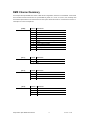
DMX Channel Summary
The Ilumipod 48 IP Optic RGBW has a total of 7 DMX channel configurations, referred to as “Personalities” in this manual
and in the fixture onboard control board. The 7 personalities are [STAG, Arc.1, Ar1.D, Arc.2, Ar2.d, Ar2.s, and HSV]. Each
of the different personalities can be accessed from the control panel. Please see section on “Control Panel Functions” on
a description on how to accomplish this.
[STAG]
[ARC.1]
[AR1.D]
[ARC.2]
CHANNEL DESCRIPTION
1
Dimmer
2
Red (step time when cus.01~10 in ch.8 is activated)
3
Green(fade time when cus.01~10 in ch.8 is activated)
4
Blue
5
White
6
Color Macro / White Balance / Hyper Color
7
Strobe
8
Auto & Custom Programs
9
Auto Speed Adjustment
10
Dimmer Speed
11
ID Address Selection
CHANNEL DESCRIPTION
1
Red
2
Green
3
Blue
CHANNEL DESCRIPTION
1
Dimmer
2
Red
3
Green
4
Blue
CHANNEL
DESCRIPTION
1
Red
2
Green
3
Blue
4
White
Ilumipod 48 IP Optic RGBW User Manual
6
5/21/2009 11:50 AM
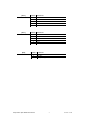
[AR2.D]
[AR2.S]
[HSV]
CHANNEL DESCRIPTION
1
Dimmer
2
Red
3
Green
4
Blue
5
White
CHANNEL DESCRIPTION
1
Dimmer
2
Red
3
Green
4
Blue
5
White
6
Strobe
CHANNEL DESCRIPTION
1
Hue
2
Saturation
3
Value (Intensity)
Ilumipod 48 IP Optic RGBW User Manual
7
5/21/2009 11:50 AM
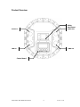
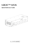
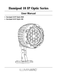
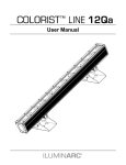
Product Overview
Safety
attachment
Power out
Power in
Power Link Out
DMX out
DMX in
Control board
Ilumipod 48 IP Optic RGBW User Manual
8
5/21/2009 11:50 AM
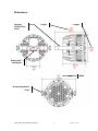
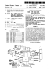
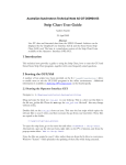
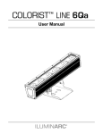
Dimensions
Hanging
bracket/ floor
stand
Length
Height
Safety cable
attachment
Width
Bracket adjustment
knob
Ilumipod 48 IP Optic RGBW User Manual
9
5/21/2009 11:50 AM
3. SETUP
AC Power
This fixture has an auto-switching switch-mode power supply that can accommodate a wide range of
input voltages. The only thing necessary to do before powering on the unit is to make sure the line
voltage you are applying is within the range of accepted voltages. This fixture will accommodate
between 100V and 240V AC 50/60 Hz. All fixtures must be powered directly off a switched circuit and
cannot be run off a rheostat (variable resistor) or dimmer circuit, even if the rheostat or dimmer
channel is used solely for a 0% to 100% switch.
This fixture is designed for power linking from one fixture to another fixture. Each fixture ships with
IP66 proprietary power input cables. Each fixture ships with a power adapter to male Edison
connector.
Warning!
All fixtures must be connected to circuits with a suitable Earth Ground.
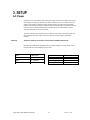
Depending on the application, the lighting fixture may require a different connector. Please refer to
the below wire color code if installing a new connector.
Wire
Connection
Connection
Pin
Brown
Blue
Green/Yellow
AC Live
AC Neutral
AC Ground
AC Live
AC Neutral
Ground(Earth)
1
2
3
Ilumipod 48 IP Optic RGBW User Manual
10
5/21/2009 11:50 AM
Mounting
Orientation
This fixture may be mounted in any safe position.
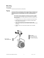
Rigging
The fixture includes a mounting yoke to which a rigging clamp can be attached. You
must supply your own clamp and make sure the clamp is capable of supporting the
weight of this fixture. It is recommended to use at least 2 mounting points per
fixture.
Note: There are 2 types of applications for this fixture: floor stand for up lighting,
and overhead use for down lighting. If you are using this fixture for up lighting,
then you must use at least 1 safety cable/chain for each fixture in addition to the
mounting brackets.
1.
If hanging the fixture for over head use, then please follow the below steps.
2.
Block access below the work area and use suitable and stable platform
when installing or servicing fixture.
3.
Safety cables must always be used, secured through safety cable
attachment. The safety cable must be capable of holding 10 times the weight
of the fixture.
4.
Verify the structure can hold 10 times the weight of all to-be installed
fixtures.
Safety Cable
Note: the cable must be
secured through the heat
sink ventilation passageway.
Hanging Clamp
Note: sold separately
Ilumipod 48 IP Optic RGBW User Manual
11
5/21/2009 11:50 AM
Fixture Linking
You will need a serial data link to run light shows of one or more fixtures using a DMX-512 controller
or to run synchronized shows on two or more fixtures set to a master/slave operating mode. The
combined number of channels required by all the fixtures on a serial data link determines the number
of fixtures the data link can support.
Important:
Fixtures on a serial data link must be daisy chained in one single line. To comply with the EIA-485
standard no more than 32 devices should be connected on one data link. Connecting more than 32
fixtures on one serial data link without the use of a DMX optically-isolated splitter may result in
deterioration of the digital DMX signal.
Maximum recommended serial data link distance: 500 meters (1640 ft.)
Maximum recommended number of fixtures on a serial data link: 32 fixtures
Data Cabling
To link fixtures together you must obtain data cables. If you choose to create your own cable please
use data-grade cables that can carry a high quality signal and are less prone to electromagnetic
interference.
DMX DAT A C ABL E
Use a Belden© 9841 or equivalent cable which meets the specifications for EIA RS-485 applications.
Standard microphone cables cannot transmit DMX data reliably over long distances. The cable will
have the following characteristics:
2-conductor twisted pair plus a shield
Maximum capacitance between conductors – 30 pF/ft.
Maximum capacitance between conductor and shield – 55 pF/ft.
Maximum resistance of 20 ohms / 1000 ft.
Nominal impedance 100 – 140 ohms
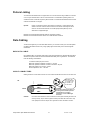
C ABL E CO NNECT O RS
Cabling must have a male XLR connector on one end and a female XLR connector on the other end.
1
3
2
DMX
INPUT
CAUTION
1
3
2
c
o
n
n
e
c
t
o
r
COMMON
1
3
2
DMX +
DMX
-
Resistance 120
ohm 1/4w between
pin 2 (DMX -) and
pin 3 (DMX +) of
the last fixture.
OUTPUT
Termination reduces signal errors. To
avoid signal transmission problems
and interference, it is always
advisable to connect a DMX signal
terminator.
c
o
n
f
i
Do gnot allow contact between the common and the fixture’s chassis ground. Grounding the common can
u a ground loop, and your fixture may perform erratically. Test cables with an ohm meter to verify
cause
r
a polarity and to make sure the pins are not grounded or shorted to the shield or each other.
correct
t
i
o
n
Ilumipod 48 IP Optic RGBW User Manual
12
5/21/2009 11:50 AM
3-PI N T O 5-PI N CO NVERSI O N CHART
Note!
If you use a controller with a 5 pin DMX output connector, you will need to use a 5 pin to 3 pin adapter.
The chart below details a proper cable conversion:
3 PIN TO 5 PIN CONVERSION CHART
Conductor
3 Pin Female (output)
5 Pin Male (Input)
Ground/Shield
Pin 1
Pin 1
Data ( - ) signal
Pin 2
Pin 2
Data ( + ) signal
Pin 3
Pin 3
Do not use
Pin 4
Do not use
Pin 5
Setting up a DMX Serial Data
Link
Universal DMX Controller
1. Connect the (male) 3 pin connector side of
the DMX cable to the output (female) 3 pin
connector of the controller.
2. Connect the end of the cable coming from
the controller which will have a (female) 3
pin connector to the input connector of the
next fixture consisting of a (male) 3 pin
connector.
This drawing provides a
general illustration of the
DMX Input/Output panel of
a lighting fixture.
3. Then, proceed to connect from the output
as stated above to the input of the following
fixture and so on.
Continue the link
Master/Slave Fixture Linking
1. Connect the (male) 3 pin connector side of the DMX cable to the output (female) 3 pin connector
of the first fixture.
2. Connect the end of the cable coming from the first fixture which will have a (female) 3 pin
connector to the input connector of the next fixture consisting of a (male) 3 pin connector. Then,
proceed to connect from the output as stated above to the input of the following fixture and so on.
Often, the setup for Master-Slave
and Standalone operation requires
that the first fixture in the chain be
initialized for this purpose via
settings in the control panel.
Secondarily, the fixtures that follow
may also require a slave setting.
Please consult the “Operating
Instructions” section in this manual
for complete instructions for this
type of setup and configuration.
Ilumipod 48 IP Optic RGBW User Manual
Slave
Slave
13
Master
5/21/2009 11:50 AM
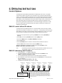
4. OPERATING INSTRUCTIONS
Control Options
The Ilumipod 48 IP Optic RGBW is addressable in the DMX range of 001 to 512. In its simplest
control form, this allows for the control of up to 46 fixtures in the 11-channel “STAG” personality;
however, a secondary ID address system exists for use in a limited DMX universe and architectural
environments. The ID address system allows the user to assign up to 66 fixtures within the same
DMX address; in effect, multiplying the control of units within a single universe to 3,036 fixtures. The
fixture’s ID address system is accessed using DMX channel 11 [STAG]. Consideration must be
placed when programming live performances or cues that need to trigger on demand or on a time
line. So, to remain within one second execution time, program no greater than 10 fixtures on ID
addressing per DMX channel.
DMX-512 control without ID address
The Ilumipod 48 IP Optic RGBW operates on 11 channels of DMX (“STAG” personality). Address
each fixture in increments of 9 channels. (I.e. 1,12,23,34, etc…) To save time you can use the same
DMX address for each fixture. All fixtures will then respond simultaneously to control. You may also
group your fixtures and address those groups alike for faster programming and control.
1. Access the control panel function by pressing the (MENU) button until the {RUN MODE} is
displayed.
2. Press (SET) and use the (UP/DOWN) buttons to select {DMX} function.
3. Then, Press (MENU) button until {DMX512 ADDRESS} is displayed.
4. Pres the (SET) button.
6. Use the (UP/DOWN) buttons to increase or decrease channels between 001 and 512.
7. Press the (SET) button to confirm action. Then press (MENU) to exit.
Deactivate ID addressing in each fixture by setting panel function {ID ON/OFF} to OFF.
{MENU} {SETTINGS} {ID ON/OFF} [OFF]
Notes:
If ID addressing is not deactivated in the fixture’s control panel function, unintended results may occur if
values are present in channel 11. Make sure values on channel 11 are set to “0”.
DMX-512 addressing with ID address
1.
Follow instructions 1 ~ 4 for DMX512 addressing.
2.
Activate ID addressing in each fixture by setting panel function {ID ON/OFF} to ON.
{MENU} {Settings) {ID ON/OFF} [ON]
3.
For every DMX512 starting address the user can set 66 separate ID addresses.
4.
Set ID addresses in each fixture by setting panel function {ID address} to incremental values.
(I.e. 1,2,3,4,5,6,etc…)
{MENU} {Settings} {ID address} [01 ~ 66]
5.
ID addresses are accessible using Channel 11 [STAG].
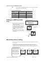
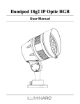
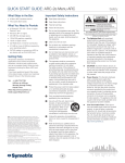
DMX Address: 001
ID Address: 01
DMX 512 Controller
Ilumipod 48 IP Optic RGBW User Manual
DMX Address: 001
ID Address: 02
DMX Address: 001
ID Address: 03
DMX Address: 012
ID Address: 01
DMX Address: 012
ID Address: 02
DMX Address: 012
ID Address: 03
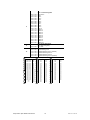
The figure above shows a simple DMX layout which has used three units at each
DMX address. The three units have different ID addresses which allows the user to
collectively control the whole group of units at that DMX address by setting Channel
10 to 0, or to control each unit independently by first selecting the DMX address and
then by using Channel 11 to locate the target ID address. (Note that when using ID
addresses it is also possible to activate ADAS which allows for even more option with
DMX addressing and control.
14
2009-05-21 11:50 AM
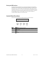
Setting the DMX address
Each fixture requires a "start address" from 1 to 512. A fixture requiring one or more channels for
control begins to read the data on the channel indicated by the start address. For example, a fixture
that occupies or uses 7 channels of DMX and was addressed to start on DMX channel 100, would
read data from channels: 100, 101, 102, 103, 104, 105 and 106. Choose start addresses so that the
channels used do not overlap and note the start address selected for future reference. The Ilumipod
48 IP Optic RGBW uses up to11 channels of DMX. If this is your first time using DMX, we
recommend reading the DMX Primer in the Appendix Section.
Control Panel Functions
All fixture functions and settings are accessible via the built-in control panel interface.
MENU
UP
SET
DOWN
BUTTON
MENU
FUNCTION
Exits from the current menu or function
SET
Enables the currently displayed menu or sets the currently selected value in to the
selected function
Navigates upwards through the menu list and increases the numeric value when in a
function
Navigates downwards through the menu list and decreases the numeric value when
in a function
UP
DOWN
Ilumipod 48 IP Optic RGBW User Manual
15
2009-05-21 11:50 AM
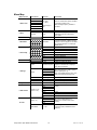
Menu Map
M AIN FUNCTION
1. Static Color
2. Auto
SUB-FUNCTION
Dimmer
Red
Green
Blue
Color Macros
Strobe
Auto
Personal
SELECTION
000 ~ 255*
(0 ~ 100%)
*Strobe range is
0~20
(1~10)
(1~10)
3. DMX Address
001 ~ 512
4. Run Mode
DMX~Slave
ID
HSV
STAG
Arc.1
Ar1.d
Arc 2
Ar2.d
Ar2.s
0-66
On~Off
Upload
*Password required
5. Personality
6. ID Address
7. Settings
Dimmer
Power
RGB to White
RESET Parameter
8. Key-Lock
9. Edit Custom
Custom (1~10)
-(Scene 01-30)
White (1~11)
10. Calib.
RGB to White
Ilumipod 48 IP Optic RGBW User Manual
Off
dim 1
dim 2
dim 3
dim 4
Normal~High
Yes~No
*Password required
On~Off
Red
Green
Blue
White
Strobe
Time
Fade
Red
Green
Blue
White
INSTRUCTION
User can combine Red, Green and Blue
to generate a custom color
Select strobing frequency between 0
and 20Hz
Choose from 10 automatic programs
Choose from 10 programs that be
customized under the “edit custom”
menu option
Sets the DMX starting address
Sets the operating mode for the fixture:
to receive signal from a DMX controller
(DMX) or to receive signal from the DMX
out of another Ilumipod ™ 48 IP Optic
RGBW (Slave)
3-channel: hue, saturation, value
11-channel RGBW+D
3-channel RGB
4-channel RGB+D
4-channel RGBW
5-channel RGBW+D
6-channel RGBW+D+strobe
Assigns the ID address to a fixture
Enables or disables ID ADAS
Performs an upload of the custom
programs to another fixture. Displays
“End!” when successful
Select linear dimmer by [off] or special
dimmer speed [dim1~4]
[dim1] is the fastest dimming curve, and
[dim4] is the slowest dimming curve
Enables HyperColor™ mode
Enables or disables RGB to White
Performs a factory reset
Enables or Disables password lockout
(0~255)
(0~20)
(0~255)
(0~255)
Sets Custom White Balance by
adjusting the maximum fader value
(0~255)
This setting presets and switches RGB
to full power (Off) or RGB auto-mix to
white (On)
On ~ Off
16
2009-05-21 11:50 AM
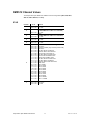
DMX512 Channel Values
The Ilumipod 48 IP Optic RGBW has 7 DMX512 channel configurations [HSV, STAG, ARC1,
ARC1+D, ARC2, ARC2+D, and Ar2.s].
STAG
CHANNEL
VALUE
1
000 255
2
000 255
3
000 255
4
000 255
5
000 255
6
000
006
021
031
051
071
081
091
111
131
151
171
191
201
206
211
216
221
226
231
236
241
246
251
7
000 004
005 255
005
020
030
050
070
090
095
110
130
150
170
190
200
205
210
215
220
225
230
235
240
245
250
255
Ilumipod 48 IP Optic RGBW User Manual
FUNCTION
Dimmer
0 100%
Red
(or STEP TIME when CUS.01-10 is activated)
0 100%
Green
(or FADE TIME when CUS.01-10 is activated)
0 100%
Blue
0 100%
White
0 100%
Color Macro + White Balance + HyperColor™
No Function
HyperColor™ Mode (only in Normal power mode)
No Function
Red 100%/ Green Up/ Blue 0%
Red Down/ Green 100%/ Blue 0%
Red 0%/ Green 100%/ Blue Up
Red 100%/ Green 0%/ Blue Down
Red 0%/ Green Down/Blue 100%
Red Up/ Green 0%/Blue 100%
Red 100%/ Green 0%/ Blue Down
Red 100%/ Green Up/ Blue Up
Red Down/ Green Down/ Blue 100%
RGBW 100%
White 1:3200K
White 2: 3400K
White 3: 4200K
White 4: 4900K
White 5: 5600K
White 6: 5900K
White 7: 6500K
White 8: 7200K
White 9: 8000K
White 10: 8500K
White 11: 10000K
Strobe
No Function
0 20Hz
17
2009-05-21 11:50 AM
8
000
010
020
030
040
050
060
070
080
090
100
110
120
130
140
150
160
170
180
190
200
009
019
029
039
049
059
069
079
089
099
109
119
129
139
149
159
169
179
189
199
255
9
000 255
10
000
010
070
130
190
009
069
129
189
255
Auto + Custom Programs
No Function
Auto 1
Auto 2
Auto 3
Auto 4
Auto 5
Auto 6
Auto 7
Auto 8
Auto 9
Auto 10
Custom 1
Custom 2
Custom 3
Custom 4
Custom 5
Custom 6
Custom 7
Custom 8
Custom 9
Custom 10
Auto Speed Adjustment
(only when using ch.8)
0 100%
Dimmer Speed
Linear dimming curve
Nonlinear dimming curve 1 (fastest)
Nonlinear dimming curve 2
Nonlinear dimming curve 3
Nonlinear dimming curve 4 (slowest)
CHANNEL 11 (ID ADDRESS SELECTION)
000 009
010 019
020 029
030 039
040 049
050 059
060 069
070 079
080 089
090 099
100 109
110 119
120 129
130 139
140 149
150 159
160 169
170 179
180 189
190 199
200 209
210
211
All IDs
ID 1
ID 2
ID 3
ID 4
ID 5
ID 6
ID 7
ID 8
ID 9
ID 10
ID 11
ID 12
ID 13
ID 14
ID 15
ID 16
ID 17
ID 18
ID 19
ID 20
ID 21
ID 22
Ilumipod 48 IP Optic RGBW User Manual
212
213
214
215
216
217
218
219
220
221
222
223
224
225
226
227
228
229
230
231
232
233
234
ID 23
ID 24
ID 25
ID 26
ID 27
ID 28
ID 29
ID 30
ID 31
ID 32
ID 33
ID 34
ID 35
ID 36
ID 37
ID 38
ID 39
ID 40
ID 41
ID 42
ID 43
ID 44
ID 45
18
235
236
237
238
239
240
241
242
243
244
245
246
247
248
249
250
251
252
253
254
255
ID 46
ID 47
ID 48
ID 49
ID 50
ID 51
ID 52
ID 53
ID 54
ID 55
ID 56
ID 57
ID 58
ID 59
ID 60
ID 61
ID 62
ID 63
ID 64
ID 65
ID 66
2009-05-21 11:50 AM
Important Notes about STAG DMX Operation
MASTER DIMMER
Channels 1 controls the intensity of the currently projected color
When the slider is at the highest position (255), then the intensity of the output is at the
maximum.
RED, GREEN BLUE AND WHITE COLOR SELECTION
Channels 2, 3 4 and 5 control the intensity ratio of each of the Red, Green, Blue,& White
LEDs.
Channels 1, 2 3 and 4 can be combined together to create over 4.2 billion color
combinations.
STROBE
Channel 7 controls the strobe of Channels 1 through 5.
Channel 7 has priority over Channels 2, 3, 4 & 5.
Speed of the strobe is adjustable from 0 to 20 Hz.
COLOR MACROS
Channel 6 selects the required Color Macro.
Channel 6 has priority over Channels 2, 3, 4, 5 & 7.
Channel 1 is used to control the intensity of the current Color Macro.
ID ADDRESS SELECTION
Use channel 11 to select ID addressed fixtures.
Each independent DMX address can have up to 66 ID addressed fixtures.
ID address “0” allows control of all fixtures simultaneously.
AUTO & CUSTOM PROGRAMS
Chanel 8 selects the preset Auto/Custom programs 1~10
When activating the Auto/Custom programs, it is then possible to control the Step time
and Fade time by using Channels 2 & 3 respectively.
Channel 8 has priority over channels 2-7.
DIMMER SPEED
Channel 10 is for selecting the dimmer mode and dimmer speed.
When channel 10 is not activated, then RGBW and Master Dimmer are linear.
The dimmer modes 1, 2, 3, and 4 are different speeds of the nonlinear dimming curves.
Ilumipod 48 IP Optic RGBW User Manual
19
2009-05-21 11:50 AM
HSV
CHANNEL
VALUE
FUNCTION
1
000 255
Hue
0 100%
2
000 255
3
000 255
Saturation
0 100%
Value
0 100%
Note: In HSV mode, Hue stands for the visible light, such as red, yellow, and cyan, etc.
Saturation refers to the dominance of hue in the color; when saturation is at 100%, then
the color is at its purest. Value is the color’s brightness; when value is at 100%, then the
color is at its brightest.
Ar2.s
CHANNEL
VALUE
FUNCTION
1
000 255
Dimmer
0 100%
2
000 255
3
000 255
4
000 255
5
000 255
6
000 255
Red
0 100%
Green
0 100%
Blue
0 100%
White
0 100%
Strobe
0 20Hz
Ilumipod 48 IP Optic RGBW User Manual
20
2009-05-21 11:50 AM
Arc.1
CHANNEL
VALUE
FUNCTION
1
000 255
Red
0 100%
2
000 255
3
000 255
Green
0 100%
Blue
0 100%
Ar1.d
CHANNEL
VALUE
FUNCTION
1
000 255
Dimmer
0 100%
2
000 255
3
000 255
4
000 255
Red
0 100%
Green
0 100%
Blue
0 100%
CHANNEL
VALUE
FUNCTION
1
000 255
Red
0 100%
2
000 255
3
000 255
4
000 255
Green
0 100%
Blue
0 100%
White
0 100%
CHANNEL
VALUE
FUNCTION
1
000 255
Dimmer
0 100%
2
000 255
3
000 255
4
000 255
5
000 255
Arc.2
Ar2.d
Red
0 100%
Green
0 100%
Blue
0 100%
White
0 100%
Ilumipod 48 IP Optic RGBW User Manual
21
2009-05-21 11:50 AM
Contact Us
Wor l d Wi de
General Information ILUMINARC™
th
3000 North 29 Court
Hollywood, FL 33020
voice: (954) 923-3680
fax:
(954) 929-5560 (ATTN: ILUMINARC™)
World Wide Web
www.ILUMINARC.com
5. APPENDIX
DMX Primer
There are 512 channels in a DMX-512 connection. Channels may be assigned in any manner. A
fixture capable of receiving DMX 512 will require one or a number of sequential channels. The user
must assign a starting address on the fixture that indicates the first channel reserved in the controller.
There are many different types of DMX controllable fixtures and they all may vary in the total number
of channels required. Choosing a start address should be planned in advance. Channels should
never overlap. If they do, this will result in erratic operation of the fixtures whose starting address is
set incorrectly. You can however, control multiple fixtures of the same type using the same starting
address as long as the intended result is that of unison movement or operation. In other words, the
fixtures will be slaved together and all respond exactly the same.
DMX fixtures are designed to receive data through a serial Daisy Chain. A Daisy Chain connection is
where the DATA OUT of one fixture connects to the DATA IN of the next fixture. The order in which
the fixtures are connected is not important and has no effect on how a controller communicates to
each fixture. Use an order that provides for the easiest and most direct cabling. Connect fixtures
using shielded two conductor twisted pair cable with three pin XLR male to female connectors. The
shield connection is pin 1, while pin 2 is Data Negative (S-) and pin 3 is Data positive (S+).
Ilumipod 48 IP Optic RGBW User Manual
22
2009-05-21 11:50 AM
General Maintenance
To maintain optimum performance and minimize wear fixtures should be cleaned frequently. Usage
and environment are contributing factors in determining frequency. As a general rule, fixtures should
be cleaned at least twice a month. Dust build up reduces light output performance and can cause
overheating. This can lead to reduced LED life and increased mechanical wear. Be sure to power off
fixture before conducting maintenance.
Unplug fixture from power. Use a vacuum or air compressor and a soft brush to remove dust
collected on external vents and internal components; be sure to prevent the fans from turning during
this process, as it can cause damage to the fans. Clean all glass when the fixture is cold with a mild
solution of glass cleaner or Isopropyl Alcohol and a soft lint free cotton cloth or lens tissue. Apply
solution to the cloth or tissue and drag dirt and grime to the outside of the lens. Gently polish optical
surfaces until they are free of haze and lint.
The cleaning of external optical lenses must be carried out periodically to optimize light output.
Cleaning frequency depends on the environment in which the fixture operates: damp, smoky or
particularly dirty surrounding can cause greater accumulation of dirt on the unit’s optics. Clean with
soft cloth using normal glass cleaning fluid. Always dry the parts carefully. Clean the external optics at
least every 20 days.
Returns Procedure
Returned merchandise must be sent prepaid and in the original packing, call tags will not be issued.
Package must be clearly labeled with a Return Merchandise Authorization Number (RMA #).
Products returned without an RMA # will be refused. Call ILUMINARC™ and request an RMA # prior
to shipping the fixture. Be prepared to provide the model number, serial number and a brief
description of the cause for the return. Be sure to properly pack fixture, any shipping damage
resulting from inadequate packaging is the customer’s responsibility. ILUMINARC™ reserves the
right to use its own discretion to repair or replace product(s). As a suggestion, proper UPS packing or
double-boxing is always a safe method to use.
Note:
If you are given an RMA #, please include the following information on a piece of
paper inside the box:
1)
Your name
2)
Your address
3)
Your phone number
4)
The RMA #
5)
A brief description of the symptoms
Claims
Damage incurred in shipping is the responsibility of the shipper; therefore the damage must be
reported to the carrier upon receipt of merchandise. It is the customer's responsibility to notify and
submit claims with the shipper in the event that a fixture is damaged due to shipping. Any other claim
for items such as missing component/part, damage not related to shipping, and concealed damage,
must be made within seven (7) days of receiving merchandise.
Ilumipod 48 IP Optic RGBW User Manual
23
2009-05-21 11:50 AM
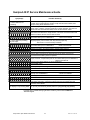
Ilumipod 48 IP Service Maintenance Guide
Symptom(s)
Possible Solution(s)
1 or more LED’s are not
illuminating
1 or more LED’s are producing
very low output
Breaker/Fuse keeps blowing
Device has no power
Fixture is not responding to DMX
Clean the fixture regularly to avoid any such failure. This fixture is convection
cooled, which means that if the surface is kept clean and free of debris, then
proper cooling will be allowed to occur
An LED may have failed, resulting in an open circuit. In this event, all of the red,
green, blue, or white in a single module will no longer illuminate. This does not
mean that all of the LEDs have failed, but the circuit is wired in series.
An LED may have failed, resulting in a short circuit. In this event, only the single
LED which has failed will no longer function. This does not mean that all of the
LEDs have failed, but the circuit is wired in series.
-Note: In the event of LED failure, a replacement LED PCB assembly may be
purchased directly from ILUMINARC™
Part#: P222-C2LEDP
Check that the lens assembly is installed properly. If the lens assembly is not
aligned properly over the LEDs, then they will not project fully
-See section on Lens Assembly Installation
-Note: In the event of LED failure, a replacement LED PCB assembly may be
purchased directly from ILUMINARC™
Part#: P222-C2LEDP
Check total load placed on the electrical circuit
Check for a short in the electrical wiring: internal and/or external
Check device’s fuse (internal)
Check for power on Mains
Check cable connections The Ilumipod 48 IP IP-66 cables must be firmly
connected and locked in place for operation
-Note: In the event of autoswitching transformer failure, the unit can be sent in for
repair; however, a replacement part can be ordered directly from ILUMINARC™
Part#: P140-C2ELTR
Check Control Panel settings for correct addressing
Check DMX cables
Check polarity switch settings on the controller
Check cable connections
Call service technician
-Note: In the event of Display PCB failure, a replacement PCB can be ordered
directly from ILUMINARC™
Part#: P170-C2DISP
Use only DMX cables
Loss of signal
Install terminator
Stand alone operation
The display is only showing: ####
Note: Keep DMX cables separated from power cables or black lights
This fixture has built-in, automatic programs that may be triggered from the
onboard Control Board
The password lockout has been enabled. You may enter the user-set password,
or you may use the factory default password: “[UP]-[DOWN]-[UP]-[DOWN]
If you still have a problem after trying the above solutions, please contact ILUMINARC™
Technical Support.
Ilumipod 48 IP Optic RGBW User Manual
24
2009-05-21 11:50 AM
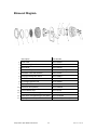
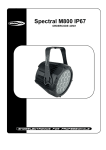
Blow-out Diagram.
Description
Part Number
1 Front cover
P111-C2FRNT
2 Glass watertight seal
P111-C2SEAL
3 Glass cover
P111-C2GLAS
4 Lens Assembly
Fixture model specific
5 LED Metal-Core PCB assembly
P222-C2LEDP
6 Hanging bracket/Floor stand
P111-C2BRKT
7 Electronic transformer
P140-C2ELTR
8 5V voltage regulator PCB
P170-5VREGP
9 Display PCB
P170-C2DISP
10 LED Driver PCB (master)
P172-C2DRVR
11 Control Board cover
P111-C2CVR
12 Cable strain relief/watertight seal-DMX
P111-C2CSSIG
12 Cable strain relief/watertight seal-power
P111-C2CSPWR
13 Display/Master IC chip
P170-C2MIC (not shown)
Ilumipod 48 IP Optic RGBW User Manual
25
2009-05-21 11:50 AM
TM
LED Life: ILUMINARC rates LED lifetime based on lumen depreciation of 70% of the original output, with data provided
by the manufacturer of the LED. Data from the manufacturer of the LED are not independently verified or measured by
TM
ILUMINARC . When the fixture is operating in optimal environmental conditions, the LED lifetime is rated to be 50,000 to
70,000 hours by the LED manufacturer.
LED Binning: LED manufacturers sort LEDs into “bins”, based on variances in color, output intensity and the frequency at
TM
which the semiconductor operates. ILUMINARC strives to hold its LED manufacturers to the highest standards of
binning to optimize consistency in output from fixture to fixture. However, the availability of a single bin cannot be
TM
guaranteed. With that in mind, ILUMINARC has developed a rigorous control system to seek the best achievable
consistency in color and output.
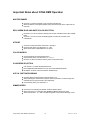
Color Rendering Index (CRI): CRI is an industry standard method to compare properties of different types of light sources.
There are known limitations and inconsistencies related to CRI. Results may vary depending on the environmental factors
involved. For this reason, the US Department of Energy (DOE) states that CRI should be considered as one point of
reference among others in evaluating white LED products and systems.
The following is an excerpt of recommendations from the DOE:
1. Identify the visual tasks to be performed under the light source. If color fidelity under different light sources is critically
important (for example in a space where color or fabric comparisons are made under both daylight and electric lighting),
CRI values may be a useful metric for rating LED products.
2. CRI may be compared only for light sources of equal CCT. This applies to all light sources, not only to LEDs. Also,
differences in CRI values of less than five points are not significant, e.g., light sources with 80 and 84 CRI are essentiall y
the same.
3. If color appearance is more important than color fidelity, do not exclude white light LEDs solely on the basis of relatively
low CRI values. Some LED products with CRIs as low as 25 still produce visually pleasing white light.
4. Evaluate LED systems in person and, if possible, on-site when color fidelity or color appearance are important issues.
Source: DOE publication: PNNL-SA-56891,
January 2008
Ilumipod 48 IP Optic RGBW User Manual
26
2009-05-21 11:50 AM
Technical Specifications
WEIGHT & DIMENSIONS
Length ................................................................................................................................. 12 in (305 mm)
Width ..................................................................................................................................... 9 in (230 mm)
Height ............................................................................................................................... 10.9 in (276 mm)
Weight ................................................................................................................................... 20 lbs (9.1 kg)
POWER
Autoswitching ........................................................................................................... 100V-40VAC 60/50Hz
Power Consumption ...................................................................................... 179.4W (1.5A) max @ 120V
Power Consumption ...................................................................................... 178.9W (0.8A) max @ 230V
Inrush Power ........................................................................................................................(1.2A) @ 120V
Inrush Power ........................................................................................................................(0.8A) @ 230V
Power Factor...........................................................................................................................1.00 @ 120V
Power Factor...........................................................................................................................0.99 @ 230V
Power Output ........................................................................ 7 units max @ 120V, 15 units max @ 230V
LIGHT SOURCE
LED ........... 48 (12 750mA Red, 12 1,000mA Green, 12 1,000mA Blue, 12 1,000mA White) 50,000 hrs
THERMAL
Maximum ambient temperature .............................................................................................104°F (40°C)
CONTROL & PROGRAMMING
Data input ................................................................................................... locking 3-pin XLR male socket
Data output ............................................................................................. locking 3-pin XLR female socket
Data pin configuration................................................................................. pin 1 shield, pin 2 (-), pin 3 (+)
Protocols ........................................................................................................................... DMX-512 USITT
DMX Channels ............................................................................................................................. 3,4,5,6,11
ORDERING INFORMATION
Ilumipod 48 Optic 15 RGBW
Ilumipod 48 Optic 30 RGBW
Ilumipod 48 Optic 15 RGBW
Ilumipod 48 Optic 30 RGBW
(white housing) .................................................................................... 11048003
(white housing) .................................................................................... 11048001
(gray housing) ...................................................................................... 11048004
(gray housing) ...................................................................................... 11048002
WARRANTY INFORMATION
Warranty.................................................................................................................. 2-year limited warranty
Ilumipod 48 IP Optic RGBW User Manual
27
2009-05-21 11:50 AM