1
User’s Manual
CS+ V3.00.00
Integrated Development Environment
User’s Manual: Project Operation
Target Device
RL78 Family
RX Family
RH850 Family
All information contained in these materials, including products and product specifications
represents information on the product at the time of publication and is subject to change by
Renesas Electronics Corp. without notice. Please review the latest information published by
Renesas Electronics Corp. through various means, including the Renesas Electronics Corp.
website (http://www.renesas.com).
www.renesas.com
Rev.1.00
2014.08
Notice
1.
Descriptions of circuits, software and other related information in this document are provided only to illustrate the operation of
semiconductor products and application examples. You are fully responsible for the incorporation of these circuits, software,
and information in the design of your equipment. Renesas Electronics assumes no responsibility for any losses incurred by you
or third parties arising from the use of these circuits, software, or information.
2.
Renesas Electronics has used reasonable care in preparing the information included in this document, but Renesas Electronics
does not warrant that such information is error free. Renesas Electronics assumes no liability whatsoever for any damages
incurred by you resulting from errors in or omissions from the information included herein.
3.
Renesas Electronics does not assume any liability for infringement of patents, copyrights, or other intellectual property rights of
third parties by or arising from the use of Renesas Electronics products or technical information described in this document. No
license, express, implied or otherwise, is granted hereby under any patents, copyrights or other intellectual property rights of
Renesas Electronics or others.
4.
You should not alter, modify, copy, or otherwise misappropriate any Renesas Electronics product, whether in whole or in part.
Renesas Electronics assumes no responsibility for any losses incurred by you or third parties arising from such alteration,
modification, copy or otherwise misappropriation of Renesas Electronics product.
5.
Renesas Electronics products are classified according to the following two quality grades: “Standard” and “High Quality”. The
recommended applications for each Renesas Electronics product depends on the product’s quality grade, as indicated below.
“Standard”:
Computers; office equipment; communications equipment; test and measurement equipment; audio and visual
equipment; home electronic appliances; machine tools; personal electronic equipment; and industrial robots etc.
“High Quality”: Transportation equipment (automobiles, trains, ships, etc.); traffic control systems; anti-disaster systems; anticrime systems; and safety equipment etc.
Renesas Electronics products are neither intended nor authorized for use in products or systems that may pose a direct threat to
human life or bodily injury (artificial life support devices or systems, surgical implantations etc.), or may cause serious property
damages (nuclear reactor control systems, military equipment etc.). You must check the quality grade of each Renesas
Electronics product before using it in a particular application. You may not use any Renesas Electronics product for any
application for which it is not intended. Renesas Electronics shall not be in any way liable for any damages or losses incurred
by you or third parties arising from the use of any Renesas Electronics product for which the product is not intended by Renesas
Electronics.
6.
You should use the Renesas Electronics products described in this document within the range specified by Renesas Electronics,
especially with respect to the maximum rating, operating supply voltage range, movement power voltage range, heat radiation
characteristics, installation and other product characteristics. Renesas Electronics shall have no liability for malfunctions or
damages arising out of the use of Renesas Electronics products beyond such specified ranges.
7.
Although Renesas Electronics endeavors to improve the quality and reliability of its products, semiconductor products have
specific characteristics such as the occurrence of failure at a certain rate and malfunctions under certain use conditions. Further,
Renesas Electronics products are not subject to radiation resistance design. Please be sure to implement safety measures to
guard them against the possibility of physical injury, and injury or damage caused by fire in the event of the failure of a Renesas
Electronics product, such as safety design for hardware and software including but not limited to redundancy, fire control and
malfunction prevention, appropriate treatment for aging degradation or any other appropriate measures. Because the evaluation
of microcomputer software alone is very difficult, please evaluate the safety of the final products or systems manufactured by
you.
8.
Please contact a Renesas Electronics sales office for details as to environmental matters such as the environmental compatibility
of each Renesas Electronics product. Please use Renesas Electronics products in compliance with all applicable laws and
regulations that regulate the inclusion or use of controlled substances, including without limitation, the EU RoHS Directive.
Renesas Electronics assumes no liability for damages or losses occurring as a result of your noncompliance with applicable laws
and regulations.
9.
Renesas Electronics products and technology may not be used for or incorporated into any products or systems whose
manufacture, use, or sale is prohibited under any applicable domestic or foreign laws or regulations. You should not use
Renesas Electronics products or technology described in this document for any purpose relating to military applications or use
by the military, including but not limited to the development of weapons of mass destruction. When exporting the Renesas
Electronics products or technology described in this document, you should comply with the applicable export control laws and
regulations and follow the procedures required by such laws and regulations.
10. It is the responsibility of the buyer or distributor of Renesas Electronics products, who distributes, disposes of, or otherwise
places the product with a third party, to notify such third party in advance of the contents and conditions set forth in this
document, Renesas Electronics assumes no responsibility for any losses incurred by you or third parties as a result of
unauthorized use of Renesas Electronics products.
11. This document may not be reproduced or duplicated in any form, in whole or in part, without prior written consent of Renesas
Electronics.
12. Please contact a Renesas Electronics sales office if you have any questions regarding the information contained in this document
or Renesas Electronics products, or if you have any other inquiries.
(Note 1) “Renesas Electronics” as used in this document means Renesas Electronics Corporation and also includes its majorityowned subsidiaries.
(Note 2) “Renesas Electronics product(s)” means any product developed or manufactured by or for Renesas Electronics.
(2012.4)
How to Use This Manual
This manual describes the role of the CS+ integrated development environment for developing applications and systems for RH850 family, RX family, and RL78 family, and provides an outline of its features.
CS+ is an integrated development environment (IDE) for RH850 family, RX family, and RL78 family, integrating the necessary tools for the development phase of software (e.g. design, implementation, and debugging) into a single platform.
By providing an integrated environment, it is possible to perform all development using just this product, without the
need to use many different tools separately.
Readers
This manual is intended for users who wish to understand the functions of the CS+ and
design software and hardware application systems.
Purpose
This manual is intended to give users an understanding of the functions of the CS+ to use
for reference in developing the hardware or software of systems using these devices.
Organization
This manual can be broadly divided into the following units.
1.GENERAL
2.FUNCTIONS
A.WINDOW REFERENCE
B.GLOSSARY
C.HOW THE MANUALS ARE ORGANIZED
D.INPUT CONVENTIONS
E.USING AN EXTERNAL BUILD TOOL
How to Read This Manual
It is assumed that the readers of this manual have general knowledge of electricity, logic
circuits, and microcontrollers.
Conventions
Data significance:
Higher digits on the left and lower digits on the right
Active low representation:
Note:
XXX (overscore over pin or signal name)
Footnote for item marked with Note in the text
Caution:
Information requiring particular attention
Remarks:
Supplementary information
Numeric representation:
Decimal ... XXXX
Hexadecimal ... 0xXXXX
All trademarks or registered trademarks in this document are the property of their respective owners.
TABLE OF CONTENTS
1.
GENERAL . . . . . . . . . . . . . . . . . . . . . . . . . . . . . . . . . . . . . . . . . . . . . . . . . . . . . . . . 7
1.1
Introduction . . . . . . . . . . . . . . . . . . . . . . . . . . . . . . . . . . . . . . . . . . . . . . . . . . . . . . . . . . . . . . . . . . . . . . . . . . . . 7
1.2
Features. . . . . . . . . . . . . . . . . . . . . . . . . . . . . . . . . . . . . . . . . . . . . . . . . . . . . . . . . . . . . . . . . . . . . . . . . . . . . . . 7
1.3
System Configuration. . . . . . . . . . . . . . . . . . . . . . . . . . . . . . . . . . . . . . . . . . . . . . . . . . . . . . . . . . . . . . . . . . . . . 8
1.4
Operating Environment . . . . . . . . . . . . . . . . . . . . . . . . . . . . . . . . . . . . . . . . . . . . . . . . . . . . . . . . . . . . . . . . . . . 9
2.
FUNCTIONS. . . . . . . . . . . . . . . . . . . . . . . . . . . . . . . . . . . . . . . . . . . . . . . . . . . . . . 10
2.1
Overview . . . . . . . . . . . . . . . . . . . . . . . . . . . . . . . . . . . . . . . . . . . . . . . . . . . . . . . . . . . . . . . . . . . . . . . . . . . . . 10
2.2
Start CS+ . . . . . . . . . . . . . . . . . . . . . . . . . . . . . . . . . . . . . . . . . . . . . . . . . . . . . . . . . . . . . . . . . . . . . . . . . . . . . 11
2.3
Create a Project . . . . . . . . . . . . . . . . . . . . . . . . . . . . . . . . . . . . . . . . . . . . . . . . . . . . . . . . . . . . . . . . . . . . . . . . 13
2.3.1
Start a project . . . . . . . . . . . . . . . . . . . . . . . . . . . . . . . . . . . . . . . . . . . . . . . . . . . . . . . . . . . . . . . . . . . . . . 16
2.3.2
Create a new project. . . . . . . . . . . . . . . . . . . . . . . . . . . . . . . . . . . . . . . . . . . . . . . . . . . . . . . . . . . . . . . . . 17
2.3.3
Add a new subproject . . . . . . . . . . . . . . . . . . . . . . . . . . . . . . . . . . . . . . . . . . . . . . . . . . . . . . . . . . . . . . . . 22
2.3.4
Create a project for multi-core [RH850] . . . . . . . . . . . . . . . . . . . . . . . . . . . . . . . . . . . . . . . . . . . . . . . . . . 23
2.4
Manipulate a Project . . . . . . . . . . . . . . . . . . . . . . . . . . . . . . . . . . . . . . . . . . . . . . . . . . . . . . . . . . . . . . . . . . . . 28
2.4.1
Open a project . . . . . . . . . . . . . . . . . . . . . . . . . . . . . . . . . . . . . . . . . . . . . . . . . . . . . . . . . . . . . . . . . . . . . 28
2.4.2
Add an existing subproject . . . . . . . . . . . . . . . . . . . . . . . . . . . . . . . . . . . . . . . . . . . . . . . . . . . . . . . . . . . . 29
2.4.3
Project is added to the favorites menu . . . . . . . . . . . . . . . . . . . . . . . . . . . . . . . . . . . . . . . . . . . . . . . . . . . 29
2.4.4
Remove a subproject from the project . . . . . . . . . . . . . . . . . . . . . . . . . . . . . . . . . . . . . . . . . . . . . . . . . . . 30
2.4.5
Change the project name . . . . . . . . . . . . . . . . . . . . . . . . . . . . . . . . . . . . . . . . . . . . . . . . . . . . . . . . . . . . . 31
2.4.6
Open a project folder in Explorer . . . . . . . . . . . . . . . . . . . . . . . . . . . . . . . . . . . . . . . . . . . . . . . . . . . . . . . 31
2.4.7
Set the build order of projects. . . . . . . . . . . . . . . . . . . . . . . . . . . . . . . . . . . . . . . . . . . . . . . . . . . . . . . . . . 32
2.4.8
Convert an e2 studio project into a CS+ project [RX] . . . . . . . . . . . . . . . . . . . . . . . . . . . . . . . . . . . . . . . . 34
2.4.9
Convert a CubeSuite project into a CS+ project. . . . . . . . . . . . . . . . . . . . . . . . . . . . . . . . . . . . . . . . . . . . 38
2.4.10
Convert a HEW project into a CS+ project . . . . . . . . . . . . . . . . . . . . . . . . . . . . . . . . . . . . . . . . . . . . . . . . 41
2.4.11
Convert a PM+ project into a CS+ project . . . . . . . . . . . . . . . . . . . . . . . . . . . . . . . . . . . . . . . . . . . . . . . . 48
2.4.12
Change the microcontroller. . . . . . . . . . . . . . . . . . . . . . . . . . . . . . . . . . . . . . . . . . . . . . . . . . . . . . . . . . . . 54
2.5
Change the Build Tool Version. . . . . . . . . . . . . . . . . . . . . . . . . . . . . . . . . . . . . . . . . . . . . . . . . . . . . . . . . . . . . 56
2.6
Set Build Target Files . . . . . . . . . . . . . . . . . . . . . . . . . . . . . . . . . . . . . . . . . . . . . . . . . . . . . . . . . . . . . . . . . . . . 56
2.6.1
Add a file to a project . . . . . . . . . . . . . . . . . . . . . . . . . . . . . . . . . . . . . . . . . . . . . . . . . . . . . . . . . . . . . . . . 56
2.6.2
Remove a file from a project. . . . . . . . . . . . . . . . . . . . . . . . . . . . . . . . . . . . . . . . . . . . . . . . . . . . . . . . . . . 60
2.6.3
Remove a file from the build target. . . . . . . . . . . . . . . . . . . . . . . . . . . . . . . . . . . . . . . . . . . . . . . . . . . . . . 61
2.6.4
Classify a file into a category . . . . . . . . . . . . . . . . . . . . . . . . . . . . . . . . . . . . . . . . . . . . . . . . . . . . . . . . . . 61
2.6.5
Change the file display order . . . . . . . . . . . . . . . . . . . . . . . . . . . . . . . . . . . . . . . . . . . . . . . . . . . . . . . . . . 63
2.6.6
Update file dependencies . . . . . . . . . . . . . . . . . . . . . . . . . . . . . . . . . . . . . . . . . . . . . . . . . . . . . . . . . . . . . 63
2.7
Make Settings for Build Operations . . . . . . . . . . . . . . . . . . . . . . . . . . . . . . . . . . . . . . . . . . . . . . . . . . . . . . . . . 66
2.7.1
Import the build options of other project . . . . . . . . . . . . . . . . . . . . . . . . . . . . . . . . . . . . . . . . . . . . . . . . . . 66
2.7.2
Set the link order of files . . . . . . . . . . . . . . . . . . . . . . . . . . . . . . . . . . . . . . . . . . . . . . . . . . . . . . . . . . . . . . 67
2.7.3
Change the build order of subprojects . . . . . . . . . . . . . . . . . . . . . . . . . . . . . . . . . . . . . . . . . . . . . . . . . . . 70
2.7.4
Display a list of build options . . . . . . . . . . . . . . . . . . . . . . . . . . . . . . . . . . . . . . . . . . . . . . . . . . . . . . . . . . 70
2.7.5
Change the build target project. . . . . . . . . . . . . . . . . . . . . . . . . . . . . . . . . . . . . . . . . . . . . . . . . . . . . . . . . 70
2.7.6
Add a build mode . . . . . . . . . . . . . . . . . . . . . . . . . . . . . . . . . . . . . . . . . . . . . . . . . . . . . . . . . . . . . . . . . . . 71
2.7.7
Change the build mode. . . . . . . . . . . . . . . . . . . . . . . . . . . . . . . . . . . . . . . . . . . . . . . . . . . . . . . . . . . . . . . 73
2.7.8
Delete a build mode . . . . . . . . . . . . . . . . . . . . . . . . . . . . . . . . . . . . . . . . . . . . . . . . . . . . . . . . . . . . . . . . . 74
2.7.9
Set the current build options as the standard for the project . . . . . . . . . . . . . . . . . . . . . . . . . . . . . . . . . . 74
2.8
Run a Build . . . . . . . . . . . . . . . . . . . . . . . . . . . . . . . . . . . . . . . . . . . . . . . . . . . . . . . . . . . . . . . . . . . . . . . . . . . 75
2.8.1
Run a build of updated files . . . . . . . . . . . . . . . . . . . . . . . . . . . . . . . . . . . . . . . . . . . . . . . . . . . . . . . . . . . 77
2.8.2
Run a build of all files . . . . . . . . . . . . . . . . . . . . . . . . . . . . . . . . . . . . . . . . . . . . . . . . . . . . . . . . . . . . . . . . 78
2.8.3
Run a build in parallel with other operations. . . . . . . . . . . . . . . . . . . . . . . . . . . . . . . . . . . . . . . . . . . . . . . 79
2.8.4
Run builds in batch with build modes . . . . . . . . . . . . . . . . . . . . . . . . . . . . . . . . . . . . . . . . . . . . . . . . . . . . 80
2.8.5
Compile/assemble individual files. . . . . . . . . . . . . . . . . . . . . . . . . . . . . . . . . . . . . . . . . . . . . . . . . . . . . . . 80
2.8.6
Stop running a build . . . . . . . . . . . . . . . . . . . . . . . . . . . . . . . . . . . . . . . . . . . . . . . . . . . . . . . . . . . . . . . . . 82
2.8.7
Save the build results to a file. . . . . . . . . . . . . . . . . . . . . . . . . . . . . . . . . . . . . . . . . . . . . . . . . . . . . . . . . . 82
2.8.8
Delete intermediate files and generated files . . . . . . . . . . . . . . . . . . . . . . . . . . . . . . . . . . . . . . . . . . . . . . 82
2.9
Save the Project File . . . . . . . . . . . . . . . . . . . . . . . . . . . . . . . . . . . . . . . . . . . . . . . . . . . . . . . . . . . . . . . . . . . . 84
2.9.1
Save the project file with a different name . . . . . . . . . . . . . . . . . . . . . . . . . . . . . . . . . . . . . . . . . . . . . . . . 84
2.9.2
Save all files . . . . . . . . . . . . . . . . . . . . . . . . . . . . . . . . . . . . . . . . . . . . . . . . . . . . . . . . . . . . . . . . . . . . . . . 85
2.9.3
Pack and save the project and this product . . . . . . . . . . . . . . . . . . . . . . . . . . . . . . . . . . . . . . . . . . . . . . . 85
2.9.4
Close a project . . . . . . . . . . . . . . . . . . . . . . . . . . . . . . . . . . . . . . . . . . . . . . . . . . . . . . . . . . . . . . . . . . . . . 89
2.10
Change the Window Layout. . . . . . . . . . . . . . . . . . . . . . . . . . . . . . . . . . . . . . . . . . . . . . . . . . . . . . . . . . . . . . . 90
2.10.1
Automatically hide panels . . . . . . . . . . . . . . . . . . . . . . . . . . . . . . . . . . . . . . . . . . . . . . . . . . . . . . . . . . . . . 90
2.10.2
Float a window . . . . . . . . . . . . . . . . . . . . . . . . . . . . . . . . . . . . . . . . . . . . . . . . . . . . . . . . . . . . . . . . . . . . . 90
2.10.3
Dock windows. . . . . . . . . . . . . . . . . . . . . . . . . . . . . . . . . . . . . . . . . . . . . . . . . . . . . . . . . . . . . . . . . . . . . . 90
2.10.4
Display multiple panels . . . . . . . . . . . . . . . . . . . . . . . . . . . . . . . . . . . . . . . . . . . . . . . . . . . . . . . . . . . . . . . 91
2.10.5
Reset the window layout. . . . . . . . . . . . . . . . . . . . . . . . . . . . . . . . . . . . . . . . . . . . . . . . . . . . . . . . . . . . . . 91
2.11
Accelerate the Startup Time of CS+. . . . . . . . . . . . . . . . . . . . . . . . . . . . . . . . . . . . . . . . . . . . . . . . . . . . . . . . . 92
2.11.1
2.12
A.
A.1
Use rapid start . . . . . . . . . . . . . . . . . . . . . . . . . . . . . . . . . . . . . . . . . . . . . . . . . . . . . . . . . . . . . . . . . . . . . 92
Manipulate CS+ on the Command Line. . . . . . . . . . . . . . . . . . . . . . . . . . . . . . . . . . . . . . . . . . . . . . . . . . . . . . 93
WINDOW REFERENCE . . . . . . . . . . . . . . . . . . . . . . . . . . . . . . . . . . . . . . . . . . . . 98
Description . . . . . . . . . . . . . . . . . . . . . . . . . . . . . . . . . . . . . . . . . . . . . . . . . . . . . . . . . . . . . . . . . . . . . . . . . . . . 98
B.
GLOSSARY . . . . . . . . . . . . . . . . . . . . . . . . . . . . . . . . . . . . . . . . . . . . . . . . . . . . . 257
C.
HOW THE MANUALS ARE ORGANIZED . . . . . . . . . . . . . . . . . . . . . . . . . . . . 258
D.
INPUT CONVENTIONS . . . . . . . . . . . . . . . . . . . . . . . . . . . . . . . . . . . . . . . . . . . 259
D.1
Input Conventions . . . . . . . . . . . . . . . . . . . . . . . . . . . . . . . . . . . . . . . . . . . . . . . . . . . . . . . . . . . . . . . . . . . . . 259
D.2
Displaying Icons at Locations of Input Errors. . . . . . . . . . . . . . . . . . . . . . . . . . . . . . . . . . . . . . . . . . . . . . . . . 259
E.
USING AN EXTERNAL BUILD TOOL . . . . . . . . . . . . . . . . . . . . . . . . . . . . . . . . . 260
E.1
Overview . . . . . . . . . . . . . . . . . . . . . . . . . . . . . . . . . . . . . . . . . . . . . . . . . . . . . . . . . . . . . . . . . . . . . . . . . . . . 260
E.2
Create a Debug-dedicated Project. . . . . . . . . . . . . . . . . . . . . . . . . . . . . . . . . . . . . . . . . . . . . . . . . . . . . . . . . 261
E.3
Add a File to a Project . . . . . . . . . . . . . . . . . . . . . . . . . . . . . . . . . . . . . . . . . . . . . . . . . . . . . . . . . . . . . . . . . . 262
E.3.1
Add a download file . . . . . . . . . . . . . . . . . . . . . . . . . . . . . . . . . . . . . . . . . . . . . . . . . . . . . . . . . . . . . . . . 262
E.3.2
Add C source files and other files . . . . . . . . . . . . . . . . . . . . . . . . . . . . . . . . . . . . . . . . . . . . . . . . . . . . . . 263
E.3.3
Remove an added file from a project . . . . . . . . . . . . . . . . . . . . . . . . . . . . . . . . . . . . . . . . . . . . . . . . . . . 266
E.4
Make Settings for Build Operations . . . . . . . . . . . . . . . . . . . . . . . . . . . . . . . . . . . . . . . . . . . . . . . . . . . . . . . . 267
E.4.1
Set the commands . . . . . . . . . . . . . . . . . . . . . . . . . . . . . . . . . . . . . . . . . . . . . . . . . . . . . . . . . . . . . . . . . 267
E.4.2
Set the build mode . . . . . . . . . . . . . . . . . . . . . . . . . . . . . . . . . . . . . . . . . . . . . . . . . . . . . . . . . . . . . . . . . 269
E.4.3
Set the target project for a build . . . . . . . . . . . . . . . . . . . . . . . . . . . . . . . . . . . . . . . . . . . . . . . . . . . . . . . 271
E.5
Run a Build . . . . . . . . . . . . . . . . . . . . . . . . . . . . . . . . . . . . . . . . . . . . . . . . . . . . . . . . . . . . . . . . . . . . . . . . . . 273
E.5.1
Run a build . . . . . . . . . . . . . . . . . . . . . . . . . . . . . . . . . . . . . . . . . . . . . . . . . . . . . . . . . . . . . . . . . . . . . . . 274
E.5.2
Run a rebuild . . . . . . . . . . . . . . . . . . . . . . . . . . . . . . . . . . . . . . . . . . . . . . . . . . . . . . . . . . . . . . . . . . . . . 275
E.5.3
Run a clean. . . . . . . . . . . . . . . . . . . . . . . . . . . . . . . . . . . . . . . . . . . . . . . . . . . . . . . . . . . . . . . . . . . . . . . 275
E.5.4
Run a rapid build. . . . . . . . . . . . . . . . . . . . . . . . . . . . . . . . . . . . . . . . . . . . . . . . . . . . . . . . . . . . . . . . . . . 277
E.5.5
Run a batch build . . . . . . . . . . . . . . . . . . . . . . . . . . . . . . . . . . . . . . . . . . . . . . . . . . . . . . . . . . . . . . . . . . 277
E.5.6
Stop running a build . . . . . . . . . . . . . . . . . . . . . . . . . . . . . . . . . . . . . . . . . . . . . . . . . . . . . . . . . . . . . . . . 278
E.5.7
Save the build results to a file. . . . . . . . . . . . . . . . . . . . . . . . . . . . . . . . . . . . . . . . . . . . . . . . . . . . . . . . . 279
Revision Record . . . . . . . . . . . . . . . . . . . . . . . . . . . . . . . . . . . . . . . . . . . . . . . . . . . . . . . 280
CS+ V3.00.00
1. GENERAL
1. GENERAL
This chapter describes the role of the CS+ integrated development environment for developing applications and systems for the microcontrollers (RH850, RX, and RL78), and provides an outline of its features.
1.1 Introduction
CS+ is an integrated development environment (IDE)Note for the microcontrollers.
By integrating the necessary tools for each development phase, it is possible to perform all phases in software development using just this product, without the need to use many different tools separately. Emphasis is placed on making the
tools work together, improving development efficiency in many different situations. As an example, the output from the
design phase is automatically reflected in the debug phase.
CS+ also has an update feature to automatically obtain this product upgrades via the network, making it simple to maintain the environment required for software development (free downloadable tools excluded).
Note
An integrated development environment is a development environment integrating the necessary tools
for all phases of software development, including preparation, design/implementation, and debugging,
into a single platform framework.
Remark
In addition to CS+, emulators and on-chip debugging emulators (emulators for microcontrollers with onchip debugging facilities built in) are provided, as well as a real-time OS package (for developing systems
using real-time OS), making a wide range of development possible.
1.2 Features
CS+'s features are shown below.
(1)
Project management
Manage project information, including source-file structure, build options, and settings for connecting to the debug
tool.
(2)
Design
The pin assignment function makes it possible to output reports called "device pin list" and "device top view" as
files, by inputting the pin-configuration status of the microcontroller.
The code generation function can output source code (device driver programs) corresponding to peripheral functions provided by the microcontroller (e.g. systems, ports, and interrupt) by selecting and entering the information
required for control in the CS+ panels.
(3)
Coding
A tree view of the files included in the project appears in a CS+ panel, and the files can be edited by linking an editor to CS+.
(4)
Build
You can configure optimization and other build options in the CS+ panels, enabling you to create efficient load
module files and a library file.
Remark
It is also possible to link to an external build tool and use it instead of the build tool provided by CS+
(see "E. USING AN EXTERNAL BUILD TOOL").
(5)
Debug
You can display your debugging tool's connection settings and debugging information in CS+ panels. There are
also many methods for executing programs, enabling you to debug your programs efficiently.
(6)
Analysis
You can analyze information while the program is executing, and display information about the functions and variables.
(7)
Updates
Communicate with the update server to get the latest version of this product.
R20UT3101EJ0100 Rev.1.00
Aug 01, 2014
Page 7 of 283
CS+ V3.00.00
1. GENERAL
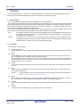
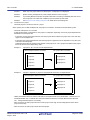
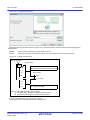
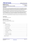
1.3 System Configuration
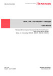
Below is shown an example of the system configuration.
Figure 1.1
System Configuration
Host machine
CS+
Design tools/Build tools, etc.
Supported target environments
Simulator
Supported target environments
Emulator
Target system
Remark
The emulator that can be connected differs depending on the microcontroller used in the project.
See "CS+ Integrated Development Environment User’s Manual: Debug Tool" for details.
R20UT3101EJ0100 Rev.1.00
Aug 01, 2014
Page 8 of 283
CS+ V3.00.00
1. GENERAL
1.4 Operating Environment
Below are the system requirements for this product.
(1)
Hardware environment
Processor: At least 1 GHz (support for hyper threading/multi-core CPU)
Main memory: At least 1 GB (2 GB or higher for Windows (64-bit OS)), 2 GB or higher recommended
Display: Resolution at least 1,204 x 768; at least 65,536 colors
Interface: USB 2.0
(2)
Software environment
- Windows Vista (32-bit OS, 64-bit OS)
- Windows 7 (32-bit OS, 64-bit OS)
- Windows 8 (32-bit OS, 64-bit OS)
- Windows 8.1 (32-bit OS, 64-bit OS)
- Microsoft .NET Framework 4
- Microsoft Visual C++ 2010 SP1 runtime libraries
- Internet Explorer 7 or higher
(3)
Supported target environments
- Emulator
- IECUBE [RL78]
- Full-spec emulator [RH850]
- E1 [RH850][RX][RL78]
- E20 [RH850][RX][RL78]
- EZ Emulator [RX][RL78]
- Simulator
R20UT3101EJ0100 Rev.1.00
Aug 01, 2014
Page 9 of 283
CS+ V3.00.00
2. FUNCTIONS
2. FUNCTIONS
This chapter covers the basic operations of CS+ and the procedure of build using CS+.
2.1 Overview
The procedure starting from the startup of CS+, creating and building projects, and up to saving projects is shown as follows.
(1)
Start CS+
Start CS+ (see "2.2 Start CS+").
(2)
Create or load a project
Create a new project, or load an existing one (see "2.3 Create a Project" and "2.4 Manipulate a Project").
(3)
Set the build tool version
Set the build tool version (see "2.5 Change the Build Tool Version").
(4)
Set build target files
Add or remove build target files and update the dependencies (see "2.6 Set Build Target Files").
(5)
Set build options
Set the options for the build tool.
Remark
(6)
Run a build
Run a build after making related settings as required (see "2.7 Make Settings for Build Operations" and "2.8 Run
a Build").
Remark
(7)
See "CS+ Integrated Development Environment User’s Manual: Build Tool Operation" for details about
setting build options.
If there are any commands you wish to run before or after the build process, on the build tool's
Property panel, from the [Common Options] tab, in the [Others] category, set the [Commands executed before build processing] and [Commands executed after build processing] properties.
If there are any commands you wish to run before or after the build process at the file level, you can
set them from the [Individual Compile Options] tab (for a C source file) and [Individual Assemble
Options] tab (for an assembly source file).
Save the project
Save the setting contents of the project to the project file (see "2.9 Save the Project File").
In addition to the above, the following operations are possible.
- Changing the window layout (see "2.10 Change the Window Layout")
- Accelerating the startup time of CS (see "2.11 Accelerate the Startup Time of CS+")
- Manipulating CS on the command line (see "2.12 Manipulate CS+ on the Command Line")
R20UT3101EJ0100 Rev.1.00
Aug 01, 2014
Page 10 of 283
CS+ V3.00.00
2. FUNCTIONS
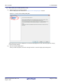
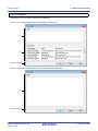
2.2 Start CS+
When CS+ is installed and started for the first time, select Windows [Start] menu >> [Programs] >> [Renesas
Electronics CS+] >> [CS+ for CC (RX,RH850)].
Remark
In Windows 8 or Windows 8.1, double-click on [CS+ for CC (RX,RH850)] on the start screen.
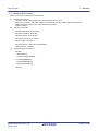
The following Main window will be opened.
Figure 2.1
Main Window
On the second and subsequent occasions, you can startup CS+ from the icon in the task tray when the rapid start (see
"2.11.1 Use rapid start") is enabled.
More than one "CS+ for CC" can be started simultaneously. However, since the setting information (customization of
panel layout or menus) is common, the setting information of the CS+ for CC that ended last is held.
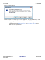
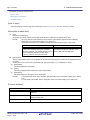
The extension of project files of "CS+ for CC" and "CS+ for CA,CX" is common. When a project file is double-clicked,
CS+ detects its contents and then starts the suitable product and load the project. If an attempt is made to open a project
of "CS+ for CA,CX" after "CS+ for CC" has been started, the following Message dialog box is opened.
R20UT3101EJ0100 Rev.1.00
Aug 01, 2014
Page 11 of 283
CS+ V3.00.00
Figure 2.2
2. FUNCTIONS
Message Dialog Box
Click [Yes] to end "CS+ for CC" and start "CS+ for CA,CX" to load the project. Click [No] to load the project by "CS+ for
CC" without changing the CS+. Click [Cancel] to halt loading. If [No] is clicked, though a project is loaded by "CS+ for
CC", it cannot be built or debugged.
Remark
The plug-ins other than the build tool, debug tool, and Editor panel are disabled by default (the disabled
plug-ins are displayed in the Output panel).
Enable desired plug-ins on the [Additional Function] tab in the Plug-in Manager dialog box opened by
selecting [Tool] menu >> [Plug-in Setting...].
To reflect the new settings, restart CS+.
R20UT3101EJ0100 Rev.1.00
Aug 01, 2014
Page 12 of 283
CS+ V3.00.00
2. FUNCTIONS
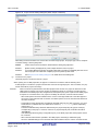
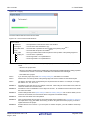
2.3 Create a Project
A project is managed by CS+ as the unit for application system development.
CS+ saves settings information used in the project such as the microcontroller, build tool, and source files, to the project
file (*.mtpj) and references it.
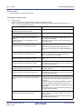
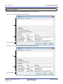
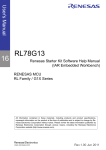
(1)
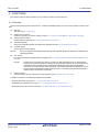
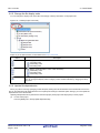
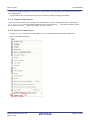
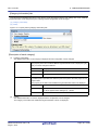
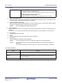
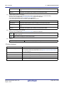
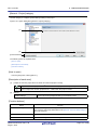
Project tree organization and detailed settings
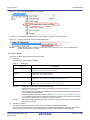
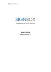
The project's settings are made on the Project Tree panel.
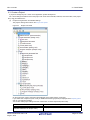
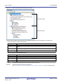
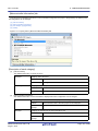
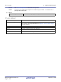
Figure 2.3
Project Tree Panel
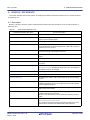
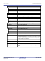
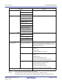
On the project tree, project components are displayed as the nodes below in a tree view.
If you select each component (node or file), its detailed information (properties) is displayed in the Property panel
and you can change its settings.
You can also make project settings from the context menu for each component (node or file).
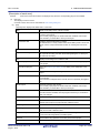
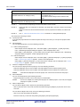
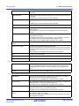
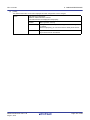
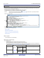
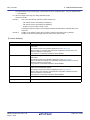
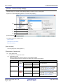
Node
Project name (Project)
(Hereafter referred to as "Project node")
R20UT3101EJ0100 Rev.1.00
Aug 01, 2014
Explanation
The project's name.
Page 13 of 283
CS+ V3.00.00
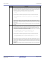
2. FUNCTIONS
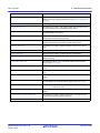
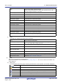
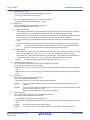
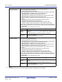
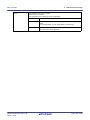
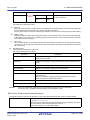
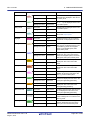
Node
(2)
Explanation
Microcontroller name (Microcontroller)
(Hereafter referred to as "Microcontroller node")
The microcontroller used in the project.
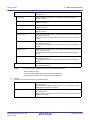
Boot Loader (Configuration Tool for Multi-core
node) [RH850]
(Hereafter referred to as "Configuration Tool for
Multi-core node")
The node for setting application projects which configure a
project for multi-core.
Note that this node is shown when the project type is a boot
loader project.
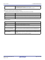
Design Tool name (Design Tool)
(Hereafter referred to as "Design Tool node")
The design tool (pin configurator, code generator, etc.) used.
Note that Code Generator (Design Tool) node is not shown
when the project type is a debug-dedicated project.
Build tool name (Build tool)
(Hereafter referred to as "Build Tool node")
The build tool (compiler, assembler, etc.) used.
When the project type is a debug-dedicated project, "None"
is shown as build tool name.
Debug tool name (Debug Tool)
(Hereafter referred to as "Debug Tool node")
The debug tool (in-circuit emulator, simulator, etc.) used.
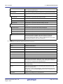
Program Analyzer (Analyze Tool)
(Hereafter referred to as "Analyze Tool node")
The analyze tool used.
Note that this node is not shown when the project type is a
debug-dedicated project.
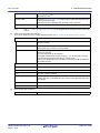
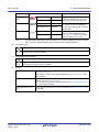
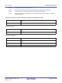
File
(Hereafter referred to as "File node")
Files registered to the project are displayed directly below
the File node.
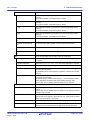
Download files
(Hereafter referred to as "Download files node")
This is a node for adding download files to the project.
Note that this node is shown only when the project type is a
debug-dedicated project.
Build tool generated files
(Hereafter referred to as "Build tool generated
files node")
This node is created during a build. Files created by the
build tools are displayed directly below the node (except for
object files).
Note that this node is not shown when the project type is a
debug-dedicated project.
Startup [RL78]
(Hereafter referred to as "Startup node")
This is a node for adding other than standard startup files to
the project. This node is always shown under the File node.
Note that this node is not shown when the project type is a
debug-dedicated project.
Category name
(Hereafter referred to as "Category node")
These user-defined categories are used to classify files into
modules.
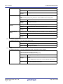
Subproject name (Subproject)
(Hereafter referred to as "Subproject node")
Subprojects added to the project.
For subprojects, see "(2) Projects and subprojects".
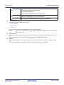
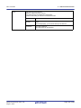
Remark 1.
Only the tools corresponding to the microcontroller in use are shown.
Remark 2.
When more than one component are selected, only the tab that is common to all the components is
displayed.
When more than one file are selected and their common properties are different, that field is left
blank.
Remark 3.
See "E. USING AN EXTERNAL BUILD TOOL" for details on a debug-dedicated project.
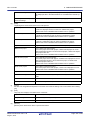
Projects and subprojects
Projects can have subprojects added to the level beneath them.
The subproject's settings information is saved to a subproject file (*.cssp).
Subprojects, for example, are used in the following ways.
- When also creating a project to create library files used in the project, create a project to create library files as a
subproject.
- When developing the same application system for different microcontrollers, create the projects that differ for
the microcontroller as subprojects.
R20UT3101EJ0100 Rev.1.00
Aug 01, 2014
Page 14 of 283
CS+ V3.00.00
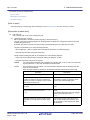
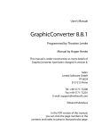
2. FUNCTIONS
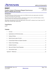
When subprojects are added, this manual call the project "main project", as opposed to its subprojects. "Project"
is a common term for the main project and subprojects.
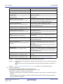
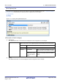
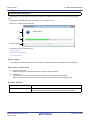
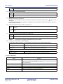
Figure 2.4
Project Tree Panel (When Subprojects Added)
Main project
Project
Subproject
Subproject
In addition, project settings and the settings for subprojects added to a project are independent and have no effect
on each other. When making the same settings between the main project and subprojects, or between differing
subprojects, select multiple nodes to set on the project tree, and make the settings with the Property panel.
Caution
A subproject cannot be added to another subproject.
Remark
See "2.3.3 Add a new subproject" and "2.4.2 Add an existing subproject", for how to add subprojects.
R20UT3101EJ0100 Rev.1.00
Aug 01, 2014
Page 15 of 283
CS+ V3.00.00
2. FUNCTIONS
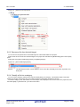
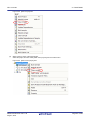
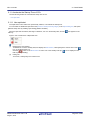
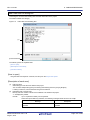
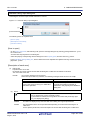
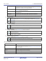
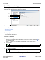
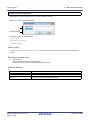
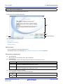
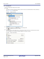
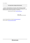
2.3.1 Start a project
On the tool bar, click
to open the Start panel. You can click the buttons on the panel to create a new project or
open an existing one.
Note that the Start panel opens automatically the first time that CS+ starts.
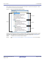
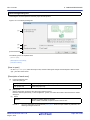
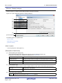
Figure 2.5
Start Panel
(1)
(2)
(3)
(4)
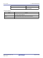
Number
Description
(1)
See "2.3.2 Create a new project".
(2)
See "2.3.4 Create a project for multi-core [RH850]".
Note that this area is minimized by default; click
to resize the area.
(3)
See "(1) Open an existing project".
(4)
See "2.4.8 Convert an e2 studio project into a CS+ project [RX]".
See "2.4.9 Convert a CubeSuite project into a CS+ project".
See "2.4.10 Convert a HEW project into a CS+ project".
See "2.4.11 Convert a PM+ project into a CS+ project".
R20UT3101EJ0100 Rev.1.00
Aug 01, 2014
Page 16 of 283
CS+ V3.00.00
2. FUNCTIONS
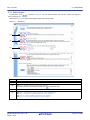
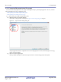
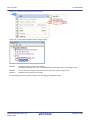
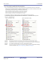
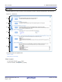
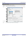
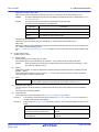
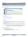
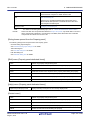
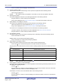
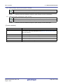
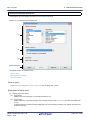
2.3.2 Create a new project
This section describes how to create a new project.
Remark
When a project for RH850 multi-core is created, see "2.3.4 Create a project for multi-core [RH850]".
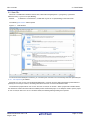
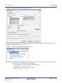
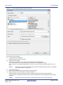
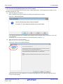
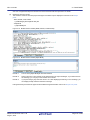
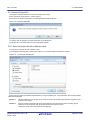
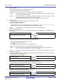
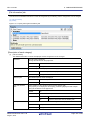
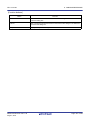
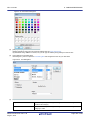
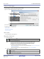
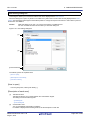
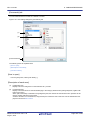
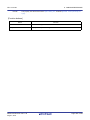
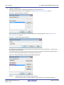
From the [Project] menu, select [Create New Project...], the Create Project dialog box will open.
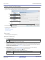
Figure 2.6
Create Project Dialog Box (When First Started)
Set the items in the order below.
(1)
Select the microcontroller type
Select the microcontroller type to use in the project on [Microcontroller].
You can select the item below.
- RH850
- RX
- RL78
(2)
Select the microcontroller
Select the microcontroller to use in the project on the [Using microcontroller] area.
If your microcontroller is not in the [Using microcontroller] area, click the [Update...] button.
You can open the CS+ Update Manager window, and check for microcontroller information updates via the network.
Caution
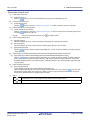
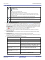
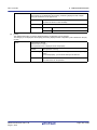
(3)
The [Update...] button is only enabled when this product is installed using the installer. It is disabled
when a packaged item is being used.
Select the project type
Select the project type to create on [Kind of project].
You can select the item below.
- Application(CC-RH/CC-RX/CC-RL)
R20UT3101EJ0100 Rev.1.00
Aug 01, 2014
Page 17 of 283
CS+ V3.00.00
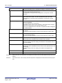
2. FUNCTIONS
Select this to generate the load module file and hex file from C source files, by using the build tool provided by
CS+.
The generated file will be the debug target.
Caution
This item is not displayed when microcontrollers for RH850 multi-core are selected in "(2) Select
the microcontroller".
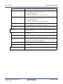
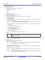
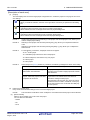
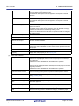
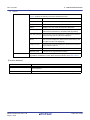
Remark 1.
If the build tool is CC-RH, the following start-up source files are generated in the project folder.
These files are also registered in the project tree.
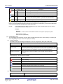
File Name
Remark 2.
cstart.asm
For defining the start-up routine from the occurrence of a reset to a
branch to the main function
iodefine.h
For defining I/O registers
main.c
For defining the empty main function
vecttbl.asm
For defining the interrupt vector table
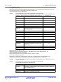
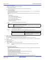
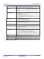
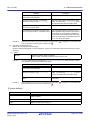
If the build tool is CC-RX, the following start-up source files are generated in the project folder.
The files marked with "OK" in the "Registration in Project Tree" column are also registered in the
project tree. When necessary, also register the files marked with "--" in the project tree.
File Name
Remark 3.
Description
Description
Registration in Project Tree
ProjectName.c
For defining the main function
OK
dbsct.c
For setting up standard sections
OK
hwsetup.c
For initializing hardware
intprg.c
For defining interrupt functions
OK
iodefine.h
For defining I/O registers
OK
lowlvl.src
For defining low-level I/O functions (source
file for assembler)
--
lowsrc.c
For defining low-level I/O functions
--
lowsrc.h
Prototypes for low-level I/O functions
--
resetprg.c
For defining initialization for C language
OK
sbrk.c
For defining the function for allocating the
heap memory
OK
sbrk.h
For defining the heap size
OK
stacksct.h
For defining pragma for the stack
OK
typedefine.h
For defining typedefine for the types used in
sbrk.c, etc.
OK
vect.h
Prototypes for interrupt vector functions
OK
vecttbl.c
For defining the interrupt vector table
OK
--
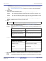
If the build tool is CC-RL, the following start-up source files are generated in the project folder.
These files are also registered in the project tree.
File Name
cstart.asm
R20UT3101EJ0100 Rev.1.00
Aug 01, 2014
Description
For defining the start-up routine from the occurrence of a reset to a
branch to the main function
The memory address and stack area need to be modified to match the
microcontroller used.
Page 18 of 283
CS+ V3.00.00
2. FUNCTIONS
File Name
Description
iodefine.h
For defining I/O registers
main.c
For defining the empty main function
- C++ Application(CC-RX)
Select this to generate the load module file and hex file from a C++ source file (only a file that has a main function) and C source files, by using build tool CC-RX provided by CS+.
The generated file will be the debug target.
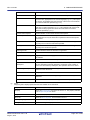
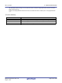
Remark
The following start-up source files are generated in the project folder.
The files marked with "OK" in the "Registration in Project Tree" column are also registered in the
project tree. When necessary, also register the files marked with "--" in the project tree.
File Name
Description
Registration in Project Tree
ProjectName.c
For defining the main function
OK
dbsct.c
For setting up standard sections
OK
hwsetup.c
For initializing hardware
intprg.c
For defining interrupt functions
OK
iodefine.h
For defining I/O registers
OK
lowlvl.src
For defining low-level I/O functions (source file
for assembler)
--
lowsrc.c
For defining low-level I/O functions
--
lowsrc.h
Prototypes for low-level I/O functions
--
resetprg.c
For defining initialization for C language
OK
sbrk.c
For defining the function for allocating the
heap memory
OK
sbrk.h
For defining the heap size
OK
stacksct.h
For defining pragma for the stack
OK
typedefine.h
For defining typedefine for the types used in
sbrk.c, etc.
OK
vect.h
Prototypes for interrupt vector functions
OK
vecttbl.c
For defining the interrupt vector table
OK
--
- Empty Application(CC-RH/CC-RX)
Select this to generate the load module file, by using build tool CC-RH/CC-RX provided by CS+.
The generated file will be the debug target.
Sample startup programs are not generated when the project is created.
- Boot Loader for Multi-core(CC-RH)
Select this to create a boot loader project for multi-core, by using build tool CC-RH provided by CS+.
A boot loader project is used to set application projects configuring a project for multi-core.
Caution
This item is displayed only when microcontrollers for RH850 multi-core are selected in "(2)
Select the microcontroller".
Remark
The following start-up source files are generated in the project folder.
These files are also registered in the project tree.
File Name
boot.asm
R20UT3101EJ0100 Rev.1.00
Aug 01, 2014
Description
For defining the processing from the occurrence of a reset to a branch to
each application project
Page 19 of 283
CS+ V3.00.00
2. FUNCTIONS
File Name
Description
iodefine.h
For defining I/O registers
vecttbl.asm
For defining the interrupt vector table
- Application for Multi-core(CC-RH)
Select this to create an application project for multi-core, by using build tool CC-RH provided by CS+.
Caution
This item is displayed only when microcontrollers for RH850 multi-core are selected in "(2)
Select the microcontroller".
Remark
The following start-up source files are generated in the project folder.
These files are also registered in the project tree.
File Name
Description
cstartm.asm
For defining the start-up routine for each application
iodefine.h
For defining I/O registers
main.c
For defining the empty main function
- Library(CC-RH/CC-RX/CC-RL)
Select this to generate a library file for a user library, by using the build tool provided by CS+.
- Debug Only
Select this to debug a load module file or hex file generated with a build tool other than the one provided by CS+
(i.e. creates a debug-dedicated project).
See "E. USING AN EXTERNAL BUILD TOOL" for details on how to create and use the debug-dedicated project.
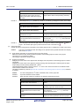
(4)
Specify the project name and location to create the project file
Specify the name of the project and the location to create the project file in [Project name] and [Place].
If you don’t create a folder with the project name under the specified location, clear the [Make the project folder]
check box.
Caution
(5)
When directly entering the location to create the project file, enter it as an absolute path.
Specify the reuse of the file structure of an existing project
When creating a project that reuses the file structure of an existing project, check [Pass the file composition of an
existing project to the new project] and specify the location of the project filename to reuse in [Project to be
passed].
Caution
You cannot specify an e2 studio, CubeSuite, High-performance Embedded Workshop, or PM+ project file.
If you wish to copy an existing e2 studio, CubeSuite, High-performance Embedded Workshop, or
PM+ project, open the project in CS+, then save it as a CS+ project (see "2.4.8 Convert an e2 studio project into a CS+ project [RX]", "2.4.9 Convert a CubeSuite project into a CS+ project", "2.4.10
Convert a HEW project into a CS+ project", "2.4.11 Convert a PM+ project into a CS+ project" for
details). Next, specify the saved project file in this area.
Remark 1.
When the version of the build tool used in the source project is different from the version of the build
tool in the project to be created, it is automatically diverted (the case that "Debug Only" is specified
with [Kind of project] is excluded).
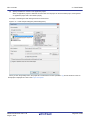
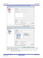
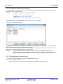
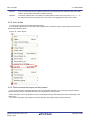
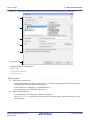
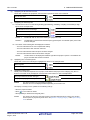
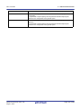
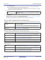
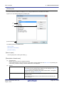
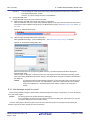
An image of the dialog box after setting the items is shown below.
R20UT3101EJ0100 Rev.1.00
Aug 01, 2014
Page 20 of 283
CS+ V3.00.00
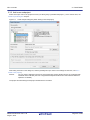
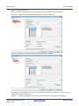
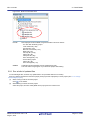
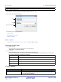
Figure 2.7
2. FUNCTIONS
Create Project Dialog Box (After Setting Items)
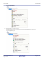
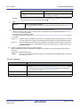
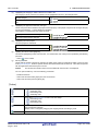
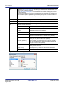
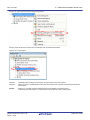
When you click the [Create] button, the project file is created in the location specified in (4) and the structure of the created project is displayed as a tree in the Project Tree panel.
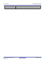
Figure 2.8
Remark
Project Tree Panel (After Creating a New Project)
After creating a project, you must add target files to the project in order to perform building or debugging.
For details on how to add these files, see the following.
- When "Application" or "Library" is selected on [Kind of project]
-> See the "2.6.1 Add a file to a project"
- When "Debug Only" is selected on [Kind of project]
-> See "E.3 Add a File to a Project"
R20UT3101EJ0100 Rev.1.00
Aug 01, 2014
Page 21 of 283
CS+ V3.00.00
2. FUNCTIONS
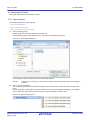
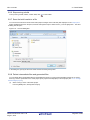
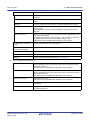
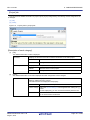
2.3.3 Add a new subproject
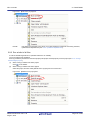
Select the Project node on the project tree and if you select [Add] >> [Add New Subproject...] on the context menu, the
Create Project dialog box will open.
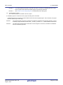
Figure 2.9
Create Project Dialog Box (When Adding a New Subproject)
After setting each item on the dialog box, click the [Create] button (For more on the settings for each item, see "2.3.2
Create a new project").
Remark
You can create a subproject with CC-RL as the build tool by reusing the file structure of a subproject with
CA78K0R as the build tool (See "CS+ Integrated Development Environment User’s Manual: Build Tool
Operation" for details).
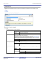
The project tree after adding the subproject will look like the one below.
R20UT3101EJ0100 Rev.1.00
Aug 01, 2014
Page 22 of 283
CS+ V3.00.00
2. FUNCTIONS
Figure 2.10 Project Tree Panel (After Adding a Subproject)
2.3.4 Create a project for multi-core [RH850]
A project for multi-core consists of a boot loader project and an application project. The application project creates programs for each CPU core, and the boot loader project manages activation of those programs.
The following shows how to create a project for multi-core by specifying the boot loader project and the application project as the main and subprojects, respectively.
On the tool bar, click
R20UT3101EJ0100 Rev.1.00
Aug 01, 2014
to open the Start panel.
Page 23 of 283
CS+ V3.00.00
Figure 2.11
2. FUNCTIONS
Start Panel
Click the [GO] button in the [Create New Multi-core Project] area to open the Create Project dialog box.
Remark
The [Create New Multi-core Project] area is minimized by default; click
R20UT3101EJ0100 Rev.1.00
Aug 01, 2014
to resize the area.
Page 24 of 283
CS+ V3.00.00
2. FUNCTIONS
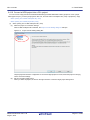
Figure 2.12 Create Project Dialog Box (When First Started)
Set the items in the order below.
(1)
Confirm the microcontroller type
[RH850] is selected on [Microcontroller].
(2)
Select the microcontroller
Select the microcontroller to use in the project on the [Using microcontroller] area.
If your microcontroller is not in the [Using microcontroller] area, click the [Update...] button.
You can open the CS+ Update Manager window, and check for microcontroller information updates via the network.
Caution
The [Update...] button is only enabled when this product is installed using the installer. It is disabled
when a packaged item is being used.
(3)
Confirm the project type
[Boot Loader for Multi-core(CC-RH)] is selected on [Kind of project].
(4)
Specify the project name and location to create the project file
Specify the name of the project and the location to create the project file in [Project name] and [Place].
If you don’t create a folder with the project name under the specified location, clear the [Make the project folder]
check box.
Caution
When directly entering the location to create the project file, enter it as an absolute path.
R20UT3101EJ0100 Rev.1.00
Aug 01, 2014
Page 25 of 283
CS+ V3.00.00
(5)
2. FUNCTIONS
Specify simultaneous creation of the application project
When an application project is created at the same time as a subproject for the boot loader project, select [Create
an application project with a boot loader project].
An image of the dialog box after setting the items is shown below.
Figure 2.13 Create Project Dialog Box (After Setting Items)
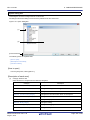
When you click the [Create] button, the project file is created in the location specified in (4) and the structure of the created project is displayed as a tree in the Project Tree panel.
R20UT3101EJ0100 Rev.1.00
Aug 01, 2014
Page 26 of 283
CS+ V3.00.00
2. FUNCTIONS
Figure 2.14 Project Tree Panel (After Creating a New Project)
Boot loader project
Application project
The start-up source files for each project are also created in the project folder and registered in the project tree.
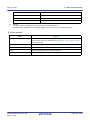
- Start-up source files for the boot loader project
File Name
Description
boot.asm
For defining the processing from the occurrence of a reset to a branch to each application
project
iodefine.h
For defining I/O registers
vecttbl.asm
For defining the interrupt vector table
- Start-up source files for the application project
File Name
Description
cstartm.asm
For defining the start-up routine for each application
iodefine.h
For defining I/O registers
main.c
For defining the empty main function
Remark 1.
The application project name is “boot-loader-project-name_App1”.
Remark 2.
Add further application projects as subprojects.
See "2.3.3 Add a new subproject" and "2.4.2 Add an existing subproject", for how to add subprojects.
R20UT3101EJ0100 Rev.1.00
Aug 01, 2014
Page 27 of 283
CS+ V3.00.00
2. FUNCTIONS
2.4 Manipulate a Project
This section describes how to manipulate a project.
2.4.1 Open a project
Use the following method to open a project.
- Open an existing project
- Open a recently used project
- Open a project from the favorites menu
(1)
Open an existing project
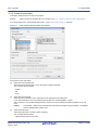
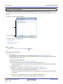
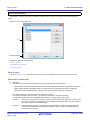
Existing projects are opened by specifying the project file.
From the [Project] menu, select [Open Project...], the Open Project dialog box will open.
Figure 2.15 Open Project Dialog Box
On the dialog box, specify the project file and click the [Open] button.
Remark
(2)
When CS+ is not running, you can start CS+ and load a project by double-clicking on that project in
Explorer.
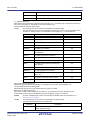
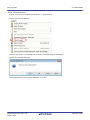
Open a recently used project
You can directly open the most recently used projects (from the most recent to the fourth most recent) from the
menu.
From the [File] menu, select [Recent Projects], the path of the recently used projects will display in a cascading
menu in order from most recent to fourth most recent. Select the project you wish to open.
Figure 2.16 [Recent Projects] Item
R20UT3101EJ0100 Rev.1.00
Aug 01, 2014
Page 28 of 283
CS+ V3.00.00
(3)
2. FUNCTIONS
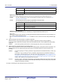
Open a project from the favorites menu
Open a project registered on the favorites menu.
From the [Project] menu, select [Favorite Projects], the path of the projects registered on the favorites menu is displayed as a cascading menu. Select the project you wish to open.
Figure 2.17 [Favorite Projects] Item
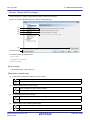
2.4.2 Add an existing subproject
Select the Project node on the project tree and if you select [Add] >> [Add Subproject...] on the context menu, the Add
Existing Subproject dialog box will open.
Figure 2.18 Add Existing Subproject Dialog Box
On the dialog box, specify the subproject file of the subproject to add and click the [Open] button.
2.4.3 Project is added to the favorites menu
You can add the currently open project to the menu as a "favorite project" (up to four projects).
From the [Project] menu, select [Favorite Projects] >> [1 - 4 Register to Favorite Project], the path of the currently open
project is registered under the [Project] menu >> [Favorite Projects].
R20UT3101EJ0100 Rev.1.00
Aug 01, 2014
Page 29 of 283
CS+ V3.00.00
2. FUNCTIONS
Figure 2.19 [Register to Favorite Project] Item
Figure 2.20 [Favorite Projects] Item (After Registering a Project)
2.4.4 Remove a subproject from the project
To remove a subproject registered to a project from that project, select the Subproject node on the project tree, and
select [Remove from Project] on the context menu.
In addition, the subproject file itself is not deleted from the file system.
Figure 2.21 [Remove from Project] Item
R20UT3101EJ0100 Rev.1.00
Aug 01, 2014
Page 30 of 283
CS+ V3.00.00
2. FUNCTIONS
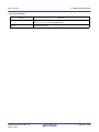
2.4.5 Change the project name
You can change the name of the project (main project or subproject) on the project tree.
Select the Project node or Subproject node and select [Rename] on the context menu.
Figure 2.22 [Rename] Item (For a Project)
Remark
After changing the project name, when you save the project, the actual name of the project file is also
changed.
2.4.6 Open a project folder in Explorer
You can open the folder where the project file for a project (main project or subproject) is saved from the project tree in
Explorer.
Select the Project node or Subproject node and select [Open Folder with Explorer] on the context menu.
Figure 2.23 [Open Folder with Explorer] Item (For a Project)
Remark
When you select [Open Folder with Explorer] from a file's context menu, the folder the file is saved in is
opened in Explorer.
R20UT3101EJ0100 Rev.1.00
Aug 01, 2014
Page 31 of 283
CS+ V3.00.00
2. FUNCTIONS
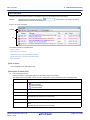
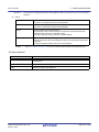
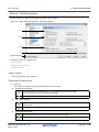
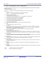
2.4.7 Set the build order of projects
Builds are run in the order of subproject, main project, but when there are multiple subprojects added, the build order of
subprojects is their display order on the project tree.
To change the display order of the subprojects on the project tree, drag the subproject to be moved and drop it on the
desired location.
However, when dependent projects have been set, builds of those projects are run first.
Dependent projects are set in the Dependent Projects Settings dialog box which is opened by selecting the [Project]
menu >> [Dependent Projects Settings...].
Figure 2.24 Dependent Projects Settings Dialog Box
Select the dependent-source project in [Project], select a project to be referenced as the dependent project from a
check box in [Dependent projects], and click the [OK] button.
Remark 1.
By default, an active project is selected in [Project].
Remark 2.
A cyclic-reference project is displayed in gray in [Dependent projects].
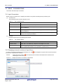
Example 1.
Builds are run in the following order when no dependent project is set.
SubProject1 -> SubProject2 -> SubProject3 -> SubProject4 -> MainProject
MainProject
SubProject1
SubProject2
SubProject3
SubProject4
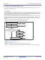
Example 2.
Builds are run in the following order when MainProject and SubProject2 are set as dependent projects for
SubProject1 and SubProject4 is set as the dependent project for SubProject2.
SubProject4 -> SubProject2 -> MainProject -> SubProject1 -> SubProject3
R20UT3101EJ0100 Rev.1.00
Aug 01, 2014
Page 32 of 283
CS+ V3.00.00
2. FUNCTIONS
MainProject
Reference
SubProject1
Reference
SubProject2
SubProject3
Reference
SubProject4
R20UT3101EJ0100 Rev.1.00
Aug 01, 2014
Page 33 of 283
CS+ V3.00.00
2. FUNCTIONS
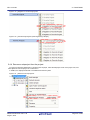
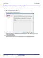
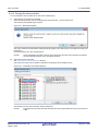
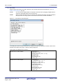
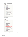
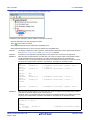
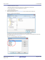
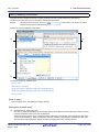
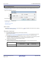
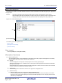
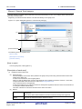
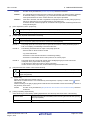
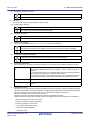
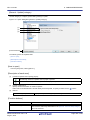
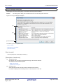
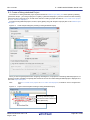
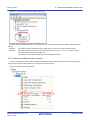
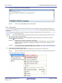
2.4.8 Convert an e2 studio project into a CS+ project [RX]
You can convert an e2 studio project for RX into a CS+ project. Select [Open Project...] from the [Project] menu with
CS+, and then select a project file (*.rcpc).
Remark
(1)
The project file (*.rcpc) for e2 studio is output by using the export function of e2 studio.
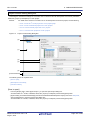
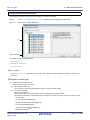
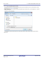
Select the project for conversion settings
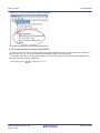
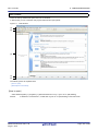
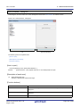
The Project Convert Setting dialog box will open.
Figure 2.25 Project Convert Setting Dialog Box
The [Project] area shows the configuration of conversion target projects as a tree; select the project for carrying
out the conversion settings.
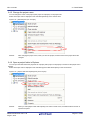
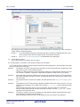
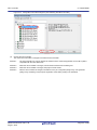
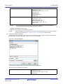
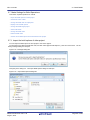
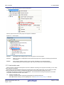
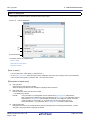
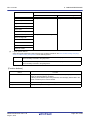
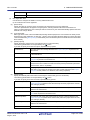
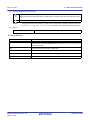
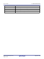
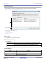
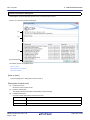
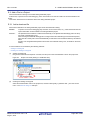
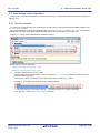
(2)
Set the conversion target project
When you select the project, the area on the right shows the conversion target project setting items.
R20UT3101EJ0100 Rev.1.00
Aug 01, 2014
Page 34 of 283
CS+ V3.00.00
2. FUNCTIONS
Figure 2.26 Project Convert Setting Dialog Box (When Project Is Selected)
After setting the microcontroller to be used for the conversion target project, and project type, name, and place of
creation settings, click the [OK] button.
(3)
Remark 1.
If you select [Backup the project composition files after conversion], immediately after the conversion the project source files and complete project are packed up and saved.
Remark 2.
See "Project Convert Setting dialog box" for details about each setting item.
Convert the CS+ project
The e2 studio project is converted to the CS+ project.
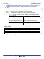
An e2 studio project is converted to a CS+ project according to the rule below.
- An e2 studio project is converted to a project with the same name as the original project. After conversion, the project
file name will be "project name.mtpj".
Remark 1.
The target for conversion is the file structure information of the e2 studio project file, configurations, build
options, file exclusion, and link order information.
However, if a different build tool is used, build options (other than include paths and defined macros) are
not converted. In addition, if extensions of object files are different, the link order is not converted.
Remark 2.
When build options have been added from the version of the target build tools in the e2 studio project to
the version of the build tools after conversion, the added options are set to the build tools' default values
after conversion.
Remark 3.
The project files after conversion are created in the folder specified in the Project Convert Setting dialog
box.
Remark 4.
Configurations of the e2 studio project are replaced with build modes of CS+ after conversion. Any characters that are not allowed in a CS+ folder name, however (\, /, :, *, ?, ", <, >, |) will be replaced by underscores ("_").
When the build mode names have 110 or more characters, they are rounded to 110 characters.
If there is another build mode with the same name after conversion, then the "_n_" (n = 1, 2, ...) will be
appended to the build mode name.
Remark 5.
If nesting is to a depth of 20 or more categories, the 20th stage and deeper stages are ignored. Files in
such categories are added to the 20th category.
When the category names have 200 or more characters, they are rounded to 200 characters.
R20UT3101EJ0100 Rev.1.00
Aug 01, 2014
Page 35 of 283
CS+ V3.00.00
2. FUNCTIONS
Remark 6.
The following e2 studio and build-tool versions are supported for conversion: e2 studio V.2.0.0.16 or
higher and CC-RX V1.00.00 or higher. The latest version of the compiler package installed on your computer is set as the version of your build tool.
Remark 7.
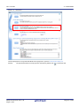
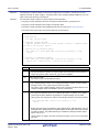
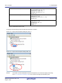
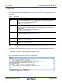
The conversion result is output to a file as project convert information.
- The project convert information file name is "ProjectConvertInformation_projectname.txt".
- The project convert information file is output to the project folder.
- The project convert information file is displayed under the File node on the Project Tree panel.
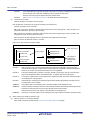
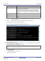
The output format of the project convert information file is shown below.
(1)Time and date on which a project was converted
(2)<IDE version>
CS+ IDE: Version [Date]
(3)<Compiler package version>
Compiler package used in e2 studio project: Version -> Compiler package used in CS+ project: Version
(4)<Options not to use(Build mode)>
Tool name of e2 studio (Tab name of build tool property in CS+)
Option
:
(5)<Options to change(Build mode)>
Tool name of e2 studio (Tab name of build tool property in CS+)
Option of e2 studio project -> Option of CS+ project
:
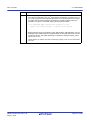
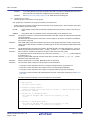
Number
Description
(1)
Time and date on which a project was converted
The time and date on which an e2 studio project was converted into a CS+ project is
output using format "dddd, mmmm dd, yyyy hh:mm:ss AM/PM".
(2)
IDE version and date
The version of CS+ and the date are output.
(3)
Compiler package version
The compiler package used in an e2 studio project and the version, and the compiler
package used in a CS+ project and the version are output.
The version of the compiler package used in a CS+ projects is the latest version in the
compiler packages which are installed in the CS+ environment.
(4)
Options not to use(Build mode)
If an option that has been set in an e2 studio project and is not used in a CS+ project
(option that has been deleted by upgrading the compiler package, and e2 studio
option) exists, the information is output for each build mode in the format shown below.
Tool name(Tab name of build tool property in CS+)
Option
:
- Build modes are output in the following order: "Debug Build", "Release Build", user-created build mode ("Debug Build" and "Release Build" are the build modes that e2 studio
provides by default. They differ depending on whether the debug information output
option is set or not.).
- "Other Options" is output if Tab name of build tool property in CS+ for Tool name does
not exist.
R20UT3101EJ0100 Rev.1.00
Aug 01, 2014
Page 36 of 283
CS+ V3.00.00
2. FUNCTIONS
Number
Description
(5)
Options to change(Build mode)
If an option that has been set in an e2 studio project and has been changed to use in a
CS+ project (option that the range the parameter can be specified has been changed,
and option that has been changed by upgrading the compiler package) exists, the
information is output for each build mode in the format shown below.
Tool name(Tab name of build tool property in CS+)
Option of e2 studio project -> Option of CS+ project
:
- Build modes are output in the following order: "Debug Build", "Release Build", user-created build mode ("Debug Build" and "Release Build" are the build modes that e2 studio
provides by default. They differ depending on whether the debug information output
option is set or not.).
- "Other Options" is output if Tab name of build tool property in CS+ for Tool name does
not exist.
R20UT3101EJ0100 Rev.1.00
Aug 01, 2014
Page 37 of 283
CS+ V3.00.00
2. FUNCTIONS
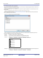
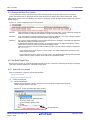
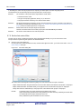
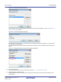
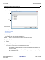
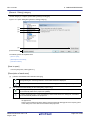
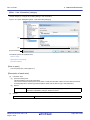
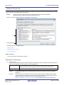
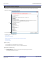
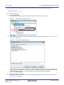
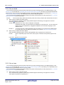
2.4.9 Convert a CubeSuite project into a CS+ project
You can convert a CubeSuite project into a CS+ project. Select [Open Project...] from the [Project] menu with CS+, and
then select a project file (*.cspj).
(1)
Select the settings for conversion
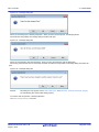
When a CubeSuite project file is selected, the following message dialog box will open.
Figure 2.27 Message Dialog Box
If you select the [Yes] button, the CubeSuite project settings are left unchanged, and the conversion to a CS+ project is carried out.
To change the microcontroller or project name, click the [No] button (continue to (2)).
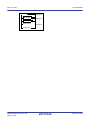
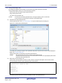
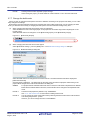
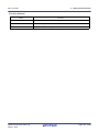
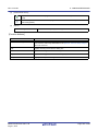
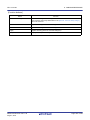
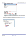
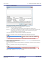
(2)
Select the project for conversion settings
The Project Convert Setting dialog box will open.
Figure 2.28 Project Convert Setting Dialog Box
The [Project] area shows the configuration of conversion target projects as a tree; select the project for carrying
out the conversion settings.
R20UT3101EJ0100 Rev.1.00
Aug 01, 2014
Page 38 of 283
CS+ V3.00.00
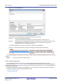
(3)
2. FUNCTIONS
Set the conversion target project
When you select the project, the area on the right shows the conversion target project setting items.
Figure 2.29 Project Convert Setting Dialog Box (When Main Project Is Selected)
Figure 2.30 Project Convert Setting Dialog Box (When Subproject Is Selected)
After setting the microcontroller to be used for the conversion target project, and project type, name, and place of
creation settings, click the [OK] button.
Remark 1.
When any subproject does not exist in a CubeSuite project, a subproject is not displayed.
R20UT3101EJ0100 Rev.1.00
Aug 01, 2014
Page 39 of 283
CS+ V3.00.00
(4)
2. FUNCTIONS
Remark 2.
If you select [Backup the project composition files after conversion], immediately after the conversion the project source files and complete project are packed up and saved.
Remark 3.
See "Project Convert Setting dialog box" for details about each setting item.
Convert the CS+ project
The CubeSuite project is converted to the CS+ project.
A CubeSuite project is converted to a CS+ project according to the rule below.
- A CubeSuite project is converted to a project with the same name as the original project. After conversion, the project
file name will be "project name.mtpj".
Remark 1.
The project file after conversion is created in the folder the CubeSuite project file was placed in. If there
is already a project file with the same name, "_number_" (number: 1, 2, ...) will be added to the file name.
Remark 2.
The build mode and build options information is not the target for conversion, if the build tool is different
from the CubeSuite project file.
R20UT3101EJ0100 Rev.1.00
Aug 01, 2014
Page 40 of 283
CS+ V3.00.00
2. FUNCTIONS
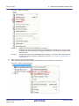
2.4.10 Convert a HEW project into a CS+ project
You can convert a High-performance Embedded Workshop (hereafter abbreviated "HEW") project into a CS+ project.
Select [Open Project...] from the [Project] menu with CS+, and then select a workspace file (*.hws) or project file (*.hwp).
- When opening from a HEW workspace file (*.hws)
- When opening from a HEW project file (*.hwp)
(1)
(a)
When opening from a HEW workspace file (*.hws)
Select the project for conversion settings
When a HEW workspace file is selected, the Project Convert Setting dialog box will open.
Figure 2.31 Project Convert Setting Dialog Box
The [Project] area shows the configuration of conversion target projects as a tree; select the project for carrying
out the conversion settings.
(b)
Set the conversion target project
When you select the project, the area on the right shows the conversion target project setting items.
R20UT3101EJ0100 Rev.1.00
Aug 01, 2014
Page 41 of 283
CS+ V3.00.00
2. FUNCTIONS
Figure 2.32 Project Convert Setting Dialog Box (When Main Project Is Selected)
Figure 2.33 Project Convert Setting Dialog Box (When Subproject Is Selected)
After setting the microcontroller to be used for the conversion target project, and project type, name, and place
of creation settings, click the [OK] button.
Caution 1.
Confirm that the microcontroller of each project is selected before clicking the [OK] button.
Caution 2.
The CPU option and section (start) option are not changed in accordance with the selected
device. If the device that differs from the HEW project is selected, confirm (change) the CPU
option and section (start) option after conversion.
R20UT3101EJ0100 Rev.1.00
Aug 01, 2014
Page 42 of 283
CS+ V3.00.00
(c)
2. FUNCTIONS
Remark 1.
When only one project exists in a HEW project, a subproject is not displayed.
Remark 2.
[Select session] is displayed only when multiple sessions exist in a project.
Remark 3.
If you select [Backup the project composition files after conversion], immediately after the conversion the project source files and complete project are packed up and saved.
Remark 4.
See "Project Convert Setting dialog box" for details about each setting item.
Convert the CS+ project
The HEW project is converted to the CS+ project.
When opening from a HEW workspace file, the project is converted in accordance with the following rules.
- The HEW workspace is not converted.
- A HEW project will be converted into a main project or subproject, depending on the inter-project dependencies
described in the workspace file.
- If there are no inter-project dependencies, then the projects will be added to the project tree in the order they
appear in the workspace file.
- If there are inter-project dependencies, then the first project to appear that is not dependent on any other projects will be the main project.
Subprojects are built in the order that they appear in the project tree. Thus, projects are added to the project
tree in the reverse of the dependency order.
Example 1.
If projects A, B, C, D have no inter-dependencies:
HEW workspace before conversion
Workspace
CS+ project after conversion
Main project A
Project A
Subproject B
Project B
Subproject C
Project C
Subproject D
Project D
Example 2.
If project C depends on project A, and projects B and D have no dependencies:
HEW workspace before conversion
Workspace
CS+ project after conversion
Main project B
Project A
Subproject A
Project B
Subproject C
Project C
Subproject D
Project D
- HEW’s placeholders which are used in build options are replaced with CS+’s placeholders. However, the converted placeholder may not indicate the correct information because the concepts differ between HEW and
CS+. Change the build options, if necessary.
- After conversion, the main project file name will be "project name.mtpj" and the subproject file name will be
"project name.mtsp".
- After conversion, the main project will be the active project.
R20UT3101EJ0100 Rev.1.00
Aug 01, 2014
Page 43 of 283
CS+ V3.00.00
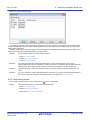
(2)
(a)
2. FUNCTIONS
When opening from a HEW project file (*.hwp)
Select the project for conversion settings
When a HEW project file is selected, the Project Convert Setting dialog box will open.
Figure 2.34 Project Convert Setting Dialog Box
The [Project] area shows the configuration of conversion target projects as a tree; select the project for carrying
out the conversion settings.
(b)
Set the conversion target project
When you select the project, the area on the right shows the conversion target project setting items.
R20UT3101EJ0100 Rev.1.00
Aug 01, 2014
Page 44 of 283
CS+ V3.00.00
2. FUNCTIONS
Figure 2.35 Project Convert Setting Dialog Box (When Project Is Selected)
After setting the microcontroller to be used for the conversion target project, and project type, name, and place
of creation settings, click the [OK] button.
(c)
Caution
Confirm that the microcontroller is selected before clicking the [OK] button.
Remark 1.
[Select session] is displayed only when multiple sessions exist in a project.
Remark 2.
If you select [Backup the project composition files after conversion], immediately after the conversion the project source files and complete project are packed up and saved.
Remark 3.
See "Project Convert Setting dialog box" for details about each setting item.
Convert the CS+ project
The HEW project is converted to the CS+ project.
When opening from a HEW project file, the project is converted in accordance with the following rules.
- A HEW project is converted to a project with the same name as the original project. After conversion, the project file name will be "project name.mtpj".
Remark 1.
When conversion is performed from the HEW project for RX into the CS+ project for RX and from the
HEW project for SuperH into the CS+ project for RH850, the target for conversion is the file structure
information of the HEW project file, configurations, build options (only a part of options if the HEW project
for SuperH is converted into the CS+ project for RH850), file exclusion, and link order information.
- When build options have been added from the version of the target build tools in the HEW project to
the version of the build tools after conversion, the added options are set to the build tools' default values after conversion.
- Configurations of the HEW project are replaced with build modes of CS+ after conversion. Any characters that are not allowed in a CS+ folder name, however (\, /, :, *, ?, ", <, >, |) will be replaced by
underscores ("_").
The build mode selected by default is determined by the project temporary file (project-name.tps)
corresponding to the project. However, if there is no project temporary file, the build mode will be
“DefaultBuild”.
If the build target file changed by Configurations(,etc.) in the HEW project files, these projects cannot
be converted.
- When the link order has been specified in the HEW project, that setting is maintained. [RX]
Since the available settings for the link order differ with the build mode, the order is converted accord-
R20UT3101EJ0100 Rev.1.00
Aug 01, 2014
Page 45 of 283
CS+ V3.00.00
2. FUNCTIONS
ing to the build mode.
When the link order has not been specified in the HEW project, linkage proceeds in alphabetical order.
- When files are classified into folders in the tree view of a HEW project, the folders are replaced with the
CS+ category after the project has been converted.
If nesting is to a depth of 20 or more folders (categories), the 20th stage and deeper stages are
ignored. Files in such folders are added to the 20th category.
Remark 2.
Except when conversion is performed from the HEW project for RX into the CS+ project for RX and from
the HEW project for SuperH into the CS+ project for RH850, the target for conversion is only the file
structure information of the HEW project file.
Remark 3.
The project files after conversion are created in the folder specified in the Project Convert Setting dialog
box.
Remark 4.
Conversion of projects that were created in HEW V.4.07 or a later version is supported.
The supported versions of the build tools of HEW are as shown below.
- SHC/C++ Ver.7.0 or higher
- H8C/C++ Ver.6.0.00 or higher
- NC30 V.5.20 Release 1 or higher
- NC308 V.5.20 Release 1 or higher
- NC100 V.1.01 Release 00 or higher
- CCRX V.1.00 Release 00 or higher
Remark 5.
The project which used the Custom Build Phase cannot be converted.
Remark 6.
The target for conversion is only the HEW project file of the Renesas Electronics compiler.
Remark 7.
The conversion result is output to a file as project convert information.
- The project convert information file name is "ProjectConvertInformation_projectname.txt".
- The project convert information file is output for each converted project (subproject).
- The project convert information file is output to the project folder of the project (subproject).
- The project convert information file is displayed the File node of the project (subproject) on the Project
Tree panel.
The output format of the project convert information file is shown below.
(1)<Options not to use(Build mode)>
Tool name of HEW (Tab name of build tool property in CS+)
Option
:
Tool name of HEW (Tab name of build tool property in CS+:file name)
Option
:
(2)<Options to change(Build mode)>
Tool name of HEW (Tab name of build tool property in CS+)
Option of HEW project -> Option of CS+ project
:
Tool name of HEW (Tab name of build tool property in CS+:file name)
Option of HEW project -> Option of CS+ project
:
R20UT3101EJ0100 Rev.1.00
Aug 01, 2014
Page 46 of 283
CS+ V3.00.00
2. FUNCTIONS
Number
(1)
Description
Options not to use(Build mode)
If an option that has been set in a HEW project and is not used in a CS+ project (option
that has been deleted by upgrading the compiler package, and HEW option) exists, the
information is output for each build mode in the format shown below.
Tool name(Tab name of build tool property in CS+)
Option
:
The information for individual compile options is output in the format shown below.
Tool name(Tab name of build tool property in CS+:file name)
Option
:
- Build modes are output in the following order: "Debug Build", "Release Build", user-created build mode ("Debug Build" and "Release Build" are the build modes that HEW provides by default. They differ depending on whether the debug information output option
is set or not.).
- "Other Options" is output if Tab name of build tool property in CS+ for Tool name does
not exist.
(2)
Options to change(Build mode)
If an option that has been set in a HEW project and has been changed to use in a CS+
project (option that the range the parameter can be specified has been changed, and
option that has been changed by upgrading the compiler package) exists, the information
is output for each build mode in the format shown below.
Tool name(Tab name of build tool property in CS+)
Option of HEW project -> Option of CS+ project
:
The information for individual compile options is output in the format shown below.
Tool name(Tab name of build tool property in CS+:file name)
Option of HEW project -> Option of CS+ project
:
- Build modes are output in the following order: "Debug Build", "Release Build", user-created build mode ("Debug Build" and "Release Build" are the build modes that HEW provides by default. They differ depending on whether the debug information output option
is set or not.).
- "Other Options" is output if Tab name of build tool property in CS+ for Tool name does
not exist.
R20UT3101EJ0100 Rev.1.00
Aug 01, 2014
Page 47 of 283
CS+ V3.00.00
2. FUNCTIONS
2.4.11 Convert a PM+ project into a CS+ project
You can convert a PM+ project into a CS+ project. Select [Open Project...] from the [Project] menu with CS+, and then
select a workspace file (*.prw) or project file (*.prj).
- When opening from a PM+ workspace file (*.prw)
- When opening from a PM+ project file (*.prj)
(1)
(a)
When opening from a PM+ workspace file (*.prw)
Select the project for conversion settings
When a PM+ workspace file is selected, the Project Convert Setting dialog box will open.
Figure 2.36 Project Convert Setting Dialog Box
The [Project] area shows the configuration of conversion target projects as a tree; select the project for carrying
out the conversion settings.
(b)
Set the conversion target project
When you select the project, the area on the right shows the conversion target project setting items.
R20UT3101EJ0100 Rev.1.00
Aug 01, 2014
Page 48 of 283
CS+ V3.00.00
2. FUNCTIONS
Figure 2.37 Project Convert Setting Dialog Box (When Main Project Is Selected)
Figure 2.38 Project Convert Setting Dialog Box (When Subproject Is Selected)
After setting the microcontroller to be used for the conversion target project, and project type, name, and place
of creation settings, click the [OK] button.
Remark 1.
When the main project is selected, the [New microcontroller] area and [Kind of project] in the
[New project] area will be invalid.
R20UT3101EJ0100 Rev.1.00
Aug 01, 2014
Page 49 of 283
CS+ V3.00.00
(c)
2. FUNCTIONS
Remark 2.
If you select [Backup the project composition files after conversion], immediately after the conversion the project source files and complete project are packed up and saved.
However, the main project is selected, this item will be invalid.
Remark 3.
See "Project Convert Setting dialog box" for details about each setting item.
Convert the CS+ project
The PM+ project is converted to the CS+ project.
PM+ projects are converted to CS+ projects according to the rules below.
- The PM+ workspace is not converted.
- PM+ project groups are divided into projects with the same name as the project group. After conversion, the
project file name will be "project group name.mtpj".
- PM+ projects are converted to subprojects with the same name as the original project. After conversion, the
subproject file name will be "project name.cssp".
- After conversion, the first subproject shown in the Project Tree will be the active project.
- After conversion, the link order in PM+ is not held.
Figure 2.39 PM+ Project Conversion Image
PM+ workspace before conversion
CS+ project after conversion
Workspace WS
Project group PG1
Project PG1
Active project
Project P11
Subproject P11
Subproject P12
Project P12
Project group PG2
Project P21
(2)
(a)
Open this project
Project PG2
Subproject P21
This project is
registered in
recently used
projects
Remark 1.
After conversion, CS+ opens the project that was converted from the PM+ project group that
includes the active project. Projects other than this project are registered in recently used projects.
However, the number of projects that exceeds four is not registered.
Remark 2.
The project settings after conversion, of those in the PM+ project group, are set to the same settings as the project listed first in the workspace file. In addition, files are not registered.
Remark 3.
If you wish to organize each of the projects into a single project after conversion, add each project
as a subproject to a single project.
Remark 4.
When loading a workspace that includes projects without build tools specified, build tools are set
according to the microcontroller.
Caution 1.
Only projects that can be loaded by PM+ and built normally can be loaded into CS+.
Caution 2.
If there is already a subproject file in the same folder and with the same file name (excluding the file
extension) as the project file, then the project file will not be saved correctly.
Change the name of the main project or the subproject on the project tree.
Caution 3.
When only one project exists in a PM+ workspace, the project will be converted to the main project.
When opening from a PM+ project file (*.prj)
Select the project for conversion settings
When a PM+ project file is selected, the Project Convert Setting dialog box will open.
R20UT3101EJ0100 Rev.1.00
Aug 01, 2014
Page 50 of 283
CS+ V3.00.00
2. FUNCTIONS
Figure 2.40 Project Convert Setting Dialog Box
The [Project] area shows the configuration of conversion target projects as a tree; select the project for carrying
out the conversion settings.
(b)
Set the conversion target project
When you select the project, the area on the right shows the conversion target project setting items.
Figure 2.41 Project Convert Setting Dialog Box (When Project Is Selected)
After setting the microcontroller to be used for the conversion target project, and project type, name, and place
of creation settings, click the [OK] button.
R20UT3101EJ0100 Rev.1.00
Aug 01, 2014
Page 51 of 283
CS+ V3.00.00
(c)
2. FUNCTIONS
Remark 1.
If you select [Backup the project composition files after conversion], immediately after the conversion the project source files and complete project are packed up and saved.
Remark 2.
See "Project Convert Setting dialog box" for details about each setting item.
Convert the CS+ project
The PM+ project is converted to the CS+ project.
PM+ projects are converted to CS+ projects according to the rules below.
- A PM+ project is converted to a project with the same name as the original project. After conversion, the project
file name will be "project name.mtpj".
Remark
When reading a project without build tools specified, build tools are set according to the microcontroller.
Caution
Only projects that can be loaded by PM+ and built normally can be loaded into CS+.
Remark 1.
The target for conversion is the file structure information of the PM+ project file and the build mode/build
options information.
The build mode and build options information is not the target for conversion, if the build tool is different
from the PM+ project file.
Remark 2.
When build options have been added from the version of the target build tools in the PM+ project to the
version of the build tools after conversion, the added options are set to the build tools' default values after
conversion.
Remark 3.
The project files after conversion are created in the folder the PM+ project file was placed in. If there is
already a project file with the same name, "_number_" (number: 1, 2, ...) will be added to the file name.
Remark 4.
After conversion, the build mode will have the same name as that of a PM+ project.
Any characters that are not allowed in a CS+ folder name, however (\, /, :, *, ?, ", <, >, |) will be replaced
by underscores ("_").
If there is another build mode with the same name after conversion, then the "_n_" (n = 1, 2, ...) will be
appended to the build mode name.
Remark 5.
Only the file structure is converted. Build options are not converted.
Remark 6.
The conversion result is output to a file as project convert information.
- The project convert information file name is "ProjectConvertInformation_projectname.txt".
- The project convert information file is output for each converted project (subproject).
- The project convert information file is output to the project folder of the project (subproject).
- The project convert information file is displayed the File node of the project (subproject) on the Project
Tree panel.
The output format of the project convert information file is shown below.
(1)Time and date on which a project was converted
(2)<IDE version>
CS+ IDE: Version [Date]
(3)<Compiler package version>
Compiler package used in PM+ project: Version -> Compiler package used
in CS+ project: Version
(4)<Options not to use(Build mode)>
Tool name of PM+ (Tab name of build tool property in CS+)
Option
:
(5)<Options to change(Build mode)>
Tool name of PM+ (Tab name of build tool property in CS+)
Option of PM+ project -> Option of CS+ project
:
R20UT3101EJ0100 Rev.1.00
Aug 01, 2014
Page 52 of 283
CS+ V3.00.00
2. FUNCTIONS
Number
Description
(1)
Time and date on which a project was converted
The time and date on which a PM+ project was converted into a CS+ project is output
using format "dddd, mmmm dd, yyyy hh:mm:ss AM/PM".
(2)
IDE version and date
The version of CS+ and the date are output.
(3)
Compiler package version
The compiler package used in a PM+ project and the version, and the compiler package
used in a CS+ project and the version are output.
The version of the compiler package used in a CS+ projects is the latest version in the
compiler packages which are installed in the CS+ environment.
(4)
Options not to use(Build mode)
If an option that has been set in a PM+ project and is not used in a CS+ project (option
that has been deleted by upgrading the compiler package, and PM+ option) exists, the
information is output for each build mode in the format shown below.
Tool name(Tab name of build tool property in CS+)
Option
:
- Build modes are output in the following order: "Debug Build", "Release Build", user-created build mode ("Debug Build" and "Release Build" are the build modes that PM+ provides by default. They differ depending on whether the debug information output option
is set or not.).
- "Other Options" is output if Tab name of build tool property in CS+ for Tool name does not
exist.
(5)
Options to change(Build mode)
If an option that has been set in a PM+ project and has been changed to use in a CS+
project (option that the range the parameter can be specified has been changed, and
option that has been changed by upgrading the compiler package) exists, the information
is output for each build mode in the format shown below.
Tool name(Tab name of build tool property in CS+)
Option of PM+ project -> Option of CS+ project
:
- Build modes are output in the following order: "Debug Build", "Release Build", user-created build mode ("Debug Build" and "Release Build" are the build modes that PM+ provides by default. They differ depending on whether the debug information output option
is set or not.).
- "Other Options" is output if Tab name of build tool property in CS+ for Tool name does not
exist.
R20UT3101EJ0100 Rev.1.00
Aug 01, 2014
Page 53 of 283
CS+ V3.00.00
2. FUNCTIONS
2.4.12 Change the microcontroller
You can change the microcontroller to be used in the created project.
(1)
Select the change for the microcontroller
Select the Microcontroller node and select [Change microcontroller...] on the context menu.
The following message dialog box will open.
Figure 2.42 Message Dialog Box
The project needs to be saved before making the following steps (The current project is overwritten by clicking the
[OK] button).
To continue the process, click the [OK] button.
Remark
(2)
When multiple Microcontroller nodes for the projects using the same microcontroller are selected,
the microcontroller settings can be changed at one time.
Select the new microcontroller
The Change Microcontroller dialog box will open.
At this time, the current microcontroller is selected in the [Change microcontroller to] area.
Figure 2.43 Change Microcontroller Dialog Box
After selecting the new microcontroller, click the [OK] button.
Remark
The [OK] button becomes valid when the selected microcontroller differs from the current microcontroller.
R20UT3101EJ0100 Rev.1.00
Aug 01, 2014
Page 54 of 283
CS+ V3.00.00
2. FUNCTIONS
Figure 2.44 Change Microcontroller Dialog Box (After Selecting New Microcontroller)
(3)
Change the microcontroller
The current microcontroller is changed to the selected microcontroller.
Remark 1.
The microcontroller can only be changed to another from the same family (RH850, RX, and RL78) that is
compatible with the same build tools.
Remark 2.
When the microcontroller is changed, it must be disconnected from the debug tool.
Remark 3.
When the microcontroller is changed, the project must be saved.
Remark 4.
After the microcontroller is changed, information for the pin configurator (design tool), code generator
(design tool), and debug tool (except for registration of the Watch panel) is not maintained.
R20UT3101EJ0100 Rev.1.00
Aug 01, 2014
Page 55 of 283
CS+ V3.00.00
2. FUNCTIONS
2.5 Change the Build Tool Version
You can change the version of the build tool (compiler package) used in the project (main project or subproject).
Select the build tool node on the project tree and select the [Common Options] tab on the Property panel. Select
[Always latest version which was installed] or the version in the [Using compiler package version] property in the [Version
Select] category.
Figure 2.45 [Using compiler package version] Property
Remark 1.
When the build tool used in the main project and subprojects is the same, you can collectively change the
build tool version by selecting all of the Build tool nodes and setting the property.
Remark 2.
If you have selected a compiler package that has not been installed (e.g. if you open a project created in
another execution environment), then that version is also displayed.
Remark 3.
If the options change depending on the compiler package, then the display of the build tool's properties
will change according to the selected version.
Properties that are hidden when the version is changed are saved in the project file's settings, and the
values will be reproduced when the properties are displayed again.
Options are changed in accordance with the following rules. Information about changes is displayed in
the Output panel.
- If you change from an older version to a newer version, the option settings will be inherited and converted (only if necessary).
- If you change from a newer version to an older version, only identical option settings will be inherited.
Options that only exist in the older version will be set to the default values.
2.6 Set Build Target Files
Before running a build, you must add the build target files (such as C source file or assembly source file) to the project.
This section explains operations on setting files in the project.
2.6.1 Add a file to a project
Files can be added to a project by the following methods.
- Adding an existing file
- Creating and adding an empty file
(1)
(a)
Adding an existing file
Add an individual files
Drag the file from Explorer or the like, and drop it onto the empty space below the project tree.
The file is added below the File node.
Figure 2.46 Project Tree Panel (File Drop Location)
Drop the file here
R20UT3101EJ0100 Rev.1.00
Aug 01, 2014
Page 56 of 283
CS+ V3.00.00
(b)
2. FUNCTIONS
Add a folder
Drag the folder from Explorer or the like, and drop it onto the empty space below the project tree. The Add
Folder and File dialog box will open.
Remark
You can also add multiple folders to the project at the same time by dragging multiple folders at
same time and dropping them onto the project tree.
Caution
When the folder with the name that is more than 200 characters is dropped, the folder is added to
the project tree as a category with the name that 201st character and after are deleted.
Figure 2.47 Add Folder and File Dialog Box
In the dialog box, select the types of the files to be added to the project and specify the number of levels of the
subfolder to be added to the project. And then click the [OK] button.
The file types to be displayed are as follows.
Project for the CC-RH compiler
C source file (*.c)
Header file (*.h; *.inc)
Assembly source file (*.asm; *.s; *.fsy)
Library file (*.lib)
Object file (*.obj)
Relocatable file (*.rel)
Text file (*.txt)
Project for the CC-RX compiler
C source file (*.c)
C++ source file (*.cpp; *.cp; *.cc)
Header file (*.h; *.hpp; *.inc)
Assembler source file (*.src; *.s)
Jump table file (*.jmp)
Symbol address file (*.fsy)
Library file (*.lib)
Object module file (*.obj)
Relocatable file (*.rel)
Text file (*.txt)
R20UT3101EJ0100 Rev.1.00
Aug 01, 2014
Page 57 of 283
CS+ V3.00.00
2. FUNCTIONS
Project for the CC-RL compiler
C source file (*.c)
Header file (*.h; *.inc)
Assembly source file (*.asm; *.s; *.fsy)
Library file (*.lib)
Object file (*.obj)
Relocatable file (*.rel)
Text file (*.txt)
Debug-dedicated project
C source file (*.c)
Header file (*.h; *.inc)
Assemble file (*.asm; *.s)
Object module file (*.obj; *.o)
Load module file (*.abs; *.lmf; *.out)
Text file (*.txt)
Remark
You can select multiple file types by left clicking while holding down the [Ctrl] or [Shift] key.
If nothing is selected, it is assumed that all types are selected.
The folder is added below the File node.
Note that on the project tree, the folder is the category.
Remark
(2)
When the category node created by the user exists, you can add a file below the node by dropping
the file onto the node (see "2.6.4 Classify a file into a category" for a category node).
Creating and adding an empty file
On the project tree, select either one of the Project node, Subproject node, or File node, and then select [Add] >>
[Add New File...] from the context menu. The Add File dialog box will open.
Figure 2.48 Add File Dialog Box
In the dialog box, specify the file to be created and then click the [OK] button.
The file types to be displayed are as follows.
Project for the CC-RH compiler
R20UT3101EJ0100 Rev.1.00
Aug 01, 2014
C source file (*.c)
Header file (*.h; *.inc)
Assembly source file (*.asm; *.s; *.fsy)
Text file (*.txt)
Page 58 of 283
CS+ V3.00.00
2. FUNCTIONS
Project for the CC-RX compiler
C source file (*.c)
C++ source file (*.cpp; *.cp; *.cc)
Header file (*.h; *.hpp; *.inc)
Assembler source file (*.src; *.s)
Text file (*.txt)
Project for the CC-RL compiler
C source file (*.c)
Header file (*.h; *.inc)
Assembly source file (*.asm; *.s; *.fsy)
Text file (*.txt)
Debug-dedicated project
C source file (*.c)
Header file (*.h; *.inc)
Assemble file (*.asm; *.s)
Text file (*.txt)
All files (*.*)
The file is added below the File node.
The project tree after adding the file and folder will look like the one below.
Figure 2.49 Project Tree Panel (After Adding File "main.c")
Figure 2.50 Project Tree Panel (After Adding Folder "src")
Remark
The location of the file added below the File node depends on the current file display order setting.
See "2.6.5 Change the file display order" for the method of changing the file display order.
R20UT3101EJ0100 Rev.1.00
Aug 01, 2014
Page 59 of 283
CS+ V3.00.00
2. FUNCTIONS
Caution 1.
If the paths differ, you can add source files with the same name.
Note, however, that if the setting of the output file name is left as the default, the output files will have the
same name, which will prevent the build from running correctly (for example, when adding
D:\sample1\func.c and D:\sample2\func.c, the default output file name for these files is both func.obj).
To avoid this problem, set the output file name for each of those files to a different name with the individual build options for the source files.
Changing the name of the C source file is made with the [Object module file name] property in the [Output File] category from the [Individual Compile Options] tab.
The changing the name of the assembly source file is made with the [Object file name] property in the
[Output File] category from the [Individual Assemble Options] tab.
See "CS+ Integrated Development Environment User’s Manual: Build Tool Operation" for how to set the
individual build options.
Caution 2.
If source files with the same name are added, the target file cannot be opened during debugging.
Caution 3.
Up to 5000 files can be added to the main project or subproject.
When a new file is added, an empty file is created in the location specified in the Add File dialog box.
By double clicking the file name on the project tree, you can open the Editor panel and edit the file.
The files that can be opened with the Editor panel are shown below.
- C source file (*.c)
- Assembly source file (*.asm, *.s)
- Symbol address file (*.fsy)
- Header file (*.h, *.inc)
- List file for assembly program (*.lst, *.lis)
- Preprocessor expanded file for assembly program (*.exp)
- Assemble list file (*.prn)
- Link order specification file (*.mtls)
- Link map file (*.map)
- Library list file (*.lbp)
- Intel Hex file (*.hex)
- Motorola S-record file (*.mot)
- Text file (*.txt)
Remark 1.
You can use one of the procedures below to open files other than those listed above in the Editor panel.
- Drag a file and drop it onto the Editor panel.
- Select a file and then select [Open with Internal Editor...] from the context menu.
Remark 2.
When the environment is set to use an external text editor on the Option dialog box, the file is opened
with the external text editor that has been set.
Other files are opened with the applications associated by the host OS.
2.6.2 Remove a file from a project
To remove the file added to a project, select the file to be removed from the project on the project tree and then select
[Remove from Project] from the context menu.
R20UT3101EJ0100 Rev.1.00
Aug 01, 2014
Page 60 of 283
CS+ V3.00.00
2. FUNCTIONS
Figure 2.51 [Remove from Project] Item
2.6.3 Remove a file from the build target
You can remove the specific file from the build target out of all the files added to the project.
Select the file to be removed from the build target on the project tree and select the [Build Settings] tab on the Property
panel.
Select [No] on the [Set as build-target] property in the [Build] category.
Figure 2.52 [Set as build-target] Property
Remark
The files that this function can be applied to are C source files, assembly source files, object files, and
library files.
2.6.4 Classify a file into a category
You can create a category under the File node and classify files by the category. This makes it easier to view files
added to the project on the project tree, and makes it easier to manage files according to function.
To create a category node, select either one of the Project node, Subproject node, or File node on the project tree, and
then select [Add] >> [Add New File...] from the context menu.
R20UT3101EJ0100 Rev.1.00
Aug 01, 2014
Page 61 of 283
CS+ V3.00.00
2. FUNCTIONS
Figure 2.53 [Add New Category] Item (For File Node)
Figure 2.54 Project Tree Panel (After Adding Category Node)
Remark 1.
The default category name is "New category".
To change the category name, you can use [Rename] from the context menu of the category node.
Remark 2.
You can also add a category node with the same name as the existing category node.
Remark 3.
Categories can be nested up to 20 levels.
You can classify files into the created category node by dragging and dropping the file.
R20UT3101EJ0100 Rev.1.00
Aug 01, 2014
Page 62 of 283
CS+ V3.00.00
2. FUNCTIONS
2.6.5 Change the file display order
You can change the display order of the files and category nodes by the buttons on the project tree.
Figure 2.55 Toolbar (Project Tree Panel)
Select any of the buttons below on the toolbar of the Project Tree panel.
Button
Description
Sorts category nodes and files in order of their names.
: Ascending order
: Descending order
: Ascending order
Sorts category nodes and files in order of their timestamp.
: Descending order
: Ascending order
: Descending order
Displays category nodes and files in order of the user definition (default).
You can change the display order of category nodes and files arbitrarily by dragging and dropping them.
2.6.6 Update file dependencies
When you perform a change (changing include file paths, adding the include statement of the header file to the source
file, etc.) that effects the file dependencies in the compile option settings or assemble option settings, you must update the
dependencies of the relevant files.
Updating file dependencies is performed for the entire project (main project and subprojects) or active project.
(1)
For the entire project
From the [Build] menu, select [Update Dependencies].
R20UT3101EJ0100 Rev.1.00
Aug 01, 2014
Page 63 of 283
CS+ V3.00.00
2. FUNCTIONS
Figure 2.56 [Update Dependencies] Item
(2)
For the active project
From the [Build] menu, select [Update Dependencies of active project].
Figure 2.57 [Update Dependencies of active project] Item
Remark
If there are files being edited with the Editor panel when updating file dependencies, then all these files
are saved.
Dependency files (include files) can be displayed under the source file on the project tree.
R20UT3101EJ0100 Rev.1.00
Aug 01, 2014
Page 64 of 283
CS+ V3.00.00
2. FUNCTIONS
Figure 2.58 Project Tree Panel (After Displaying Dependency File)
The display of the dependency files is updated on the following timings:
- When the first build is run after the project is loaded
- When
on the toolbar is clicked
- When [Update Dependencies] is selected from the [Build] menu
- When [Update Dependencies of active project] is selected from the [Build] menu
Remark 1.
The display of dependency files is valid only when the [Show dependency files in project tree] check box
in the [General - Build] category of the Option dialog box is selected.
Remark 2.
Information on the dependency files displayed on the project tree is not saved in the project file.
Caution 1.
When checking for dependences on include files, CS+ does not support cases of include files to which
conditional statements such as #if apply or for which the #include directive is commented out.
Therefore, there is a case where this product regards an include file unnecessary for a build as a necessary file (In the example below, header1.h and header5.h are judged as required for build).
#if
#include
#else
#include
#endif
0
"header1.h"
"header2.h"
/* Dependence relationship judged to exist */
/* ! zero */
/* Dependence relationship to exist */
#define
#ifdef
#include
#else
#include
#endif
AAA
AAA
"header3.h"
/* Dependence relationship to exist */
"header4.h"
/* Dependence relationship to exist */
"header5.h"
/* Dependence relationship judged to exist */
/*
#include
*/
Caution 2.
When checking for dependences on include files, CS+ does not support include statements that follow
comments or comment marks that are on the same line.
Therefore, there is a case where this product regards an include file necessary for a build as a unnecessary file (In the example below, header6.h and header7.h are judged as no-required for build).
/* comment */
#include
judged not to exist */
/*
comment
*/ #include
"header7.h"
not to exist */
R20UT3101EJ0100 Rev.1.00
Aug 01, 2014
"header6.h"
/* Dependence relationship
/* Dependence relationship judged
Page 65 of 283
CS+ V3.00.00
2. FUNCTIONS
2.7 Make Settings for Build Operations
This section explains operations on a build.
- Import the build options of other project
- Set the link order of files
- Change the build order of subprojects
- Display a list of build options
- Change the build target project
- Add a build mode
- Change the build mode
- Delete a build mode
- Set the current build options as the standard for the project
2.7.1 Import the build options of other project
You can import the build options of other project to the current project.
On the project tree, select the Build tool node, and then select [Import Build Options...] from the context menu. The following message dialog box will open.
Figure 2.59 Message Dialog Box
Click [Yes] in the dialog box. The Import Build Options dialog box will open.
Figure 2.60 Import Build Options Dialog Box
R20UT3101EJ0100 Rev.1.00
Aug 01, 2014
Page 66 of 283
CS+ V3.00.00
2. FUNCTIONS
In the dialog box, select the target project file for importing the build options and click the [Open] button.
The build options of the selected project file are imported to the current project.
Remark 1.
The conditions of the project that is importable are shown below.
- The build tool is the same.
- The type of the project (application, library, etc.) is the same.
- The project has been created by CS+ with the same version.
Remark 2.
The target build options for importing are only the general options set in the properties of the build tool.
The setting of the standard build options (see "2.7.9 Set the current build options as the standard for the
project") and the individual options are not imported.
Remark 3.
All the build modes of the import target are imported.
However, the build modes of the current project (other than DefaultBuild) are deleted.
Remark 4.
The version of the build tool to be used is imported.
2.7.2 Set the link order of files
The link order of object module files and library files is decided automatically, but you can also set the order.
The procedures for performing this operation are described below.
(1)
Open the Link Order dialog box
On the project tree, select the Build tool node, and then select [Set Link Order...] from the context menu. The Link
Order dialog box will open.
Figure 2.61 Link Order Dialog Box
The names of the following files are listed in [File] in the order that the files are input to the linker.
- Object module files which are generated from the source files added to the selected main project or subproject
- Object module files which are added directly to the project tree of the selected main project or subproject
- Library files which are added directly to the project tree of the selected main project or subproject
Remark
The default order is the order that the files are added to the project.
Object module files generated from newly added source files and newly added object module files
are added after the last object module file in the list.
Newly added library files are added to the end of the list.
R20UT3101EJ0100 Rev.1.00
Aug 01, 2014
Page 67 of 283
CS+ V3.00.00
(2)
2. FUNCTIONS
Change the file display order
By changing the display order of the files, you can set the input order of the files to the linker.
Change the file display order by one of the following procedures.
- Move the file name by using the [Up] and [Down] buttons.
- Drag and drop the file name.
- Use a link order specification file.
Remark
(a)
You can use a link order specification file to change the display order on a file basis.
The procedures for performing this operation are described below.
Generate a link order specification file
Click the [Export] button in the Link Order dialog box to open the Select Export File dialog box.
Figure 2.62 Select Export File Dialog Box
In the dialog box, specify the file (link order specification file) that is output the list of the file names displayed in
[File] in the Link Order dialog box.
Click the [Save] button to generate the link order specification file.
Caution
(b)
Only the file names are output to the link order specification file.
If a file with the same name exists, check the location of the file in the popup display after installing the link order specification file.
Edit the link order specification file
Open the link order specification file with an editor, and then change the description order of the file names.
The code example of the link order specification file is shown below.
# CS+ Vx.xx.xx Link order specification file
# SampleProject: Xxxxxx xx, xxxx
file01.obj
file03.obj
library02.lib
file02.obj
library01.lib
library03.lib
:
The following points should be noted when describing the link order specification file.
R20UT3101EJ0100 Rev.1.00
Aug 01, 2014
Page 68 of 283
CS+ V3.00.00
2. FUNCTIONS
- Describe one file name on one line.
- Uppercase characters and lowercase characters are not distinguished for the file name.
- If the line begins with "#", the line is interpreted as a comment.
- A space or tab is ignored.
(c)
Import the link order specification file
Click the [Import] button in the Link Order dialog box to open the Select Import File dialog box.
Figure 2.63 Select Import File Dialog Box
In the dialog box, select the link order specification file and click the [Open] button.
The description order of the file names are acquired from the selected link order specification file, and then they
are reflected in [File] in the Link Order dialog box.
Figure 2.64 Link Order Dialog Box (After Setting Link Order)
R20UT3101EJ0100 Rev.1.00
Aug 01, 2014
Page 69 of 283
CS+ V3.00.00
(3)
2. FUNCTIONS
Caution 1.
The file that is described in the link order specification file and is not added to the project is not
displayed.
If the corresponding file exists, the list of the file names will be displayed in the Output panel.
Caution 2.
The file that is added to the project and is not described in the link order specification file is displayed in the end of [File].
Caution 3.
If a file with the same name exists, check the location of the file in the popup display (it will
appear when you hover the mouse cursor over the file name).
To change the link order, use the [Up] and [Down] buttons, or drag and drop the file names.
Set the file link order
Click the [OK] button in the Link Order dialog box to set the input order of the files to the linker.
2.7.3 Change the build order of subprojects
Builds are run in the order of subproject, main project, but when there are multiple subprojects added, the build order of
subprojects is their display order on the project tree.
To change the display order of the subprojects on the project tree, drag the subproject to be moved and drop it on the
desired location.
2.7.4 Display a list of build options
You can display the list of build options set currently on the build tool's Property panel for the project (main project and
subproject).
Select [Build Options List] from the [Build] menu. The current settings of the options for the project will be displayed on
the [Build Tool] tab from the Output panel in the build order.
Remark
You can change the display format of the build option list.
Select the build tool node on the project tree and select the [Common Options] tab on the Property panel.
Set the [Format of build option list] property in the [Others] category.
Figure 2.65 [Format of build option list] Property
The following placeholders are supported.
%Program%: Replaces with the program name under execution.
%Options%: Replaces with the command line option under build execution.
%TargetFiles%: Replaces with the file name being compile/assemble or making link.
"%TargetFiles% : %Program% %Options%" is set by default.
2.7.5 Change the build target project
When running a build that targets a specific project (main project or subproject), you must set that project as the "active
project".
Caution
The active project will be the debug target.
Note that the active project cannot be set during connection with the debug tool; be sure to disconnect
the debug tool before setting the active project.
To set the active project, select the main project or subproject to be set as the active project on the project tree and
select [Set selected project as Active Project] from the context menu.
R20UT3101EJ0100 Rev.1.00
Aug 01, 2014
Page 70 of 283
CS+ V3.00.00
2. FUNCTIONS
Figure 2.66 [Set selected project as Active Project] Item
When a project is set as the active project, that project is underlined.
Figure 2.67 Active Project
Remark 1.
Immediately after creating a project, the main project is the active project.
Remark 2.
When you remove a subproject that set as the active project from a project, the main project will be the
active project.
Caution
When a build is started by a button on the tool bar, the build is run for the entire project.
To run a build only for the active project, start it from the context menu of the active project.
2.7.6 Add a build mode
When you wish to change the build options and macro definitions according to the purpose of the build, you can collectively change those settings.
Build options and macro definition settings are organized into what is called "build mode", and by changing the build
mode, you eliminate the necessity of changing the build options and macro definition settings every time.
The build mode prepared by default is only "DefaultBuild". Add a build mode according to the purpose of the build.
The method to add a build mode is shown below.
(1)
Create a new build mode
Creating a new build mode is performed with duplicating an existing build mode.
Select [Build Mode Settings...] from the [Build] menu. The Build Mode Settings dialog box will open.
R20UT3101EJ0100 Rev.1.00
Aug 01, 2014
Page 71 of 283
CS+ V3.00.00
2. FUNCTIONS
Figure 2.68 Build Mode Settings Dialog Box
Select the build mode to be duplicated from the build mode list and click the [Duplicate...] button. The Character
String Input dialog box will open.
Figure 2.69 Character String Input Dialog Box
In the dialog box, enter the name of the build mode to be created and then click the [OK] button. The build mode
with that name will be duplicated.
The created build mode is added to the build modes of the main project and all the subprojects which belong to the
project.
Figure 2.70 Build Mode Settings Dialog Box (After Adding Build Mode)
(2)
Change the build mode
Change the build mode to the newly created build mode (see "2.7.7 Change the build mode").
(3)
Change the setting of the build mode
Select the build tool node on the project tree and change the build options and macro definition settings on the
Property panel.
R20UT3101EJ0100 Rev.1.00
Aug 01, 2014
Page 72 of 283
CS+ V3.00.00
Remark
2. FUNCTIONS
Creating a build mode is regarded a project change.
When closing the project, you will be asked to confirm whether or not to save the build mode.
2.7.7 Change the build mode
When you wish to change the build options and macro definitions according to the purpose of the build, you can collectively change those settings.
Build options and macro definition settings are organized into what is called "build mode", and by changing the build
mode, you eliminate the necessity of changing the build options and macro definition settings every time.
(1)
When changing the build mode for the main project or subprojects
Select the Build tool node of the target project on the project tree and select the [Common Options] tab on the
Property panel.
Select the build mode to be changed to on the [Build mode] property in the [Build Mode] category.
Figure 2.71 [Build mode] Property
(2)
When changing the build mode for the entire project
Select [Build Mode Settings...] from the [Build] menu. The Build Mode Settings dialog box will open.
Figure 2.72 Build Mode Settings Dialog Box
Select the build mode to be changed from the build mode list. The selected build mode will be displayed in
[Selected build mode].
Click the [Apply to All] button. The build mode for the main project and all the subprojects which belong to the
project will be changed to the build mode selected in the dialog box.
Caution
For projects that the selected build mode does not exist, the build mode is duplicated from "DefaultBuild" with the selected build mode name, and the build mode is changed to the duplicated build
mode.
Remark 1.
The build mode prepared by default is only "DefaultBuild".
See "2.7.6 Add a build mode" for the method of adding a build mode.
Remark 2.
You can change the name of the build mode by selecting the build mode from the build mode list
and clicking the [Rename...] button.
However, you cannot change the name of "DefaultBuild".
R20UT3101EJ0100 Rev.1.00
Aug 01, 2014
Page 73 of 283
CS+ V3.00.00
2. FUNCTIONS
2.7.8 Delete a build mode
Deleting a build mode is performed with the Build Mode Settings dialog box.
Select [Build Mode Settings...] from the [Build] menu. The dialog box will open.
Figure 2.73 Build Mode Settings Dialog Box
Select the build mode to be deleted from [Build mode list] and click the [Delete] button. The Message dialog box below
will open.
Figure 2.74 Message Dialog Box
To continue with the operation, click the [OK] button in the dialog box.
The selected build mode is deleted from the project.
Caution 1.
You cannot delete "DefaultBuild".
Caution 2.
If the currently set build mode is deleted, "DefaultBuild" is set.
2.7.9 Set the current build options as the standard for the project
On the build tool's Property panel, if you add a change to the settings for the standard build options, the value of the
property will be displayed in boldface.
Figure 2.75 Property Panel (After Changing Standard Build Option)
To make the build options for the currently selected project (main project or subproject) the standard build options
(remove the boldface), select the Build tool node on the project tree and select [Set to Default Build Option for Project]
from the context menu.
R20UT3101EJ0100 Rev.1.00
Aug 01, 2014
Page 74 of 283
CS+ V3.00.00
2. FUNCTIONS
Figure 2.76 [Set to Default Build Option for Project] Item
The values of the properties after setting them as the standard build option are as shown below.
Figure 2.77 Property Panel (After Setting Standard Build Option)
Caution
When the main project is selected, only the main project settings are made. Even if subprojects are
added, their settings are not made.
2.8 Run a Build
This section explains operations related to running a build.
(1)
Build types
The following types of builds are available.
Table 2.1
Build Types
Type
(2)
Description
Build
Out of build target files, runs a build of only updated files.
-> See "2.8.1 Run a build of updated files".
Rebuild
Runs a build of all build target files.
-> See "2.8.2 Run a build of all files".
Rapid build
Runs a build in parallel with the change of the build setting.
-> See "2.8.3 Run a build in parallel with other operations".
Batch build
Runs builds in batch with the build modes that the project has.
-> See "2.8.4 Run builds in batch with build modes".
Remark 1.
Builds are run in the order of subproject, main project.
Subprojects are built in the order that they are displayed on the project tree (see "2.7.3 Change the
build order of subprojects").
Note that when the build target project depends on another project, the build of the depended project is run before the target project.
Note that if parallel build between projects (see the [General - Build] category of the Option dialog
box) is enabled and also there is no dependency between the projects, the execution order of build
is not fixed (i.e. dependent on the environment of the PC in use).
Remark 2.
If there are files being edited with the Editor panel when running a build, rebuild, or batch build, then
all these files are saved.
Speeding-up of build
Two types of facilities are provided to speed up build: simultaneous build and parallel build.
The build time can be shortened in simultaneous build by simultaneously compiling or assembling the files with a
single call of the build command and in parallel build by executing multiple build commands in parallel.
R20UT3101EJ0100 Rev.1.00
Aug 01, 2014
Page 75 of 283
CS+ V3.00.00
2. FUNCTIONS
See "CS+ Integrated Development Environment User’s Manual: Build Tool Operation" for details.
(3)
Displaying execution results
The execution results of the build (output messages of the build tool) are displayed in each tab on the Output
panel.
- Build, rebuild, or batch build
-> [All Messages] tab and [Build Tool] tab
- Rapid build
-> [Rapid Build] tab
Figure 2.78 Build Execution Results (Build, Rebuild, or Batch Build)
Figure 2.79 Build Execution Results (Rapid Build)
Remark 1.
The text in the [Rapid Build] tab becomes dimmed.
Remark 2.
When a file name or line number can be obtained from the output messages, if you double click on
the message, you can jump to the relevant line in the file.
Remark 3.
If you press the [F1] key when the cursor is on a line displaying the warning or error message, you
can display the help related to that line's message.
Files generated by the build tool appear under the Build tool generated files node on the Project Tree panel.
R20UT3101EJ0100 Rev.1.00
Aug 01, 2014
Page 76 of 283
CS+ V3.00.00
2. FUNCTIONS
Figure 2.80 Build Tool Generated Files
Remark
Files displayed under the Build tool generated files node are as follows.
- For other than the library project
Load module file (*.abs)
Intel Hex file (*.hex)
Motorola S-record file (*.mot)
Binary file (*.bin)
Link map file (*.map)
Library file (*.lib)
Library list file (*.lbp)
Error message file (*.err)
- For the library project
Library file (*.lib)
Error message file (*.err)
Caution
The Build tool generated files node is created during build.
This node will no longer appear if you reload the project after building.
2.8.1 Run a build of updated files
Out of build target files, a build of only updated files is run (hereafter referred to as "build").
Running a build is performed for the entire project (main project and subprojects) or active project (see "2.7.5 Change
the build target project").
(1)
When running a build of the entire project
Click
on the toolbar.
(2)
When running a build of the active project
Select the project, and then select [Build active project] from the context menu.
R20UT3101EJ0100 Rev.1.00
Aug 01, 2014
Page 77 of 283
CS+ V3.00.00
2. FUNCTIONS
Figure 2.81 [Build active project] Item
Remark
If the build of the included source file is not run after editing the header file and running the build,
update the file dependencies (see "2.6.6 Update file dependencies").
2.8.2 Run a build of all files
A build of all build target files is run (hereafter referred to as "rebuild").
The cross reference file is deleted.
Running a rebuild is performed for the entire project (main project and subprojects) or active project (see "2.7.5 Change
the build target project").
(1)
When running a rebuild of the entire project
Click
on the toolbar.
(2)
When running a rebuild of the active project
Select the project, and then select [Rebuild active project] from the context menu.
Figure 2.82 [Rebuild active project] Item
R20UT3101EJ0100 Rev.1.00
Aug 01, 2014
Page 78 of 283
CS+ V3.00.00
2. FUNCTIONS
2.8.3 Run a build in parallel with other operations
CS+ can automatically start a build when one of the following events occurs (hereafter referred to as "rapid build").
- When any one of the following files that are added to the project is updated: (C source file, assembly source file, symbol address file, header file, object file, relocatable file, and library file)
- When a build target file has been added to or removed from the project
- When the link order of object module files and library files is changed
- When the property of the build tool or build target file is changed
If a rapid build is enabled, it is possible to perform a build in parallel with the above operations.
To enable/disable a rapid build, select [Rapid Build] from the [Build] menu. A rapid build is enabled by default.
Figure 2.83 [Rapid Build] Item
[When a rapid build is valid]
[When a rapid build is invalid]
Remark 1.
After editing source files, it is recommend to save frequently by pressing the [Ctrl] + [S] key.
Remark 2.
Enable/Disable setting of the rapid build applies to the entire project (main project and subprojects).
Remark 3.
If you disable a rapid build while it is running, it will be stopped at that time.
Caution
This function will also be enabled in an external text editor if the [Observe registered files changing]
check box is selected in the [General - Build] category of the Option dialog box.
R20UT3101EJ0100 Rev.1.00
Aug 01, 2014
Page 79 of 283
CS+ V3.00.00
2. FUNCTIONS
2.8.4 Run builds in batch with build modes
You can run builds, rebuilds and cleans in batch with the build modes that the project (main project and subproject) has
(hereafter referred to as "batch build").
Remark
See the sections below for a build, rebuild, and clean.
- Build: See "2.8.1 Run a build of updated files".
- Rebuild: See "2.8.2 Run a build of all files".
- Clean: See "2.8.8 Delete intermediate files and generated files".
Select [Batch Build...] from the [Build] menu. The Batch Build dialog box will open.
Figure 2.84 Batch Build Dialog Box
In the dialog box, the list of the combinations of the names of the main project and subprojects in the currently opened
project and their build modes and macro definitions is displayed.
Select the check boxes for the combinations of the main project and subprojects and build modes that you wish to run a
batch build, and then click the [Build], [Rebuild], or [Clean] button.
Remark
The batch build order follows the project build order, the order of the subprojects, main project.
When multiple build modes are selected for a single main project or subproject, after running builds of the
subproject with all the selected build modes, the build of the next subproject or main project is run.
2.8.5 Compile/assemble individual files
You can just compile or assemble for each source file added to the project.
(1)
When compiling a C source file
Select the C source file on the project tree and select the [Compile] from the context menu.
R20UT3101EJ0100 Rev.1.00
Aug 01, 2014
Page 80 of 283
CS+ V3.00.00
2. FUNCTIONS
Figure 2.85 [Compile] Item
(2)
When assembling an assembly source file
Select the assembly source file on the project tree and select the [Assemble] from the context menu.
Figure 2.86 [Assemble] Item
R20UT3101EJ0100 Rev.1.00
Aug 01, 2014
Page 81 of 283
CS+ V3.00.00
2. FUNCTIONS
2.8.6 Stop running a build
To stop running a build, rebuild, or batch build, click
on the toolbar.
2.8.7 Save the build results to a file
You can save the execution results of the build (output messages of the build tool) that displayed on the Output panel.
Select the [Build Tool] tab on the panel, and then select [Save Output - Build Tool As...] from the [File] menu. The Save
As dialog box will open.
Figure 2.87 Save As Dialog Box
In the dialog box, specify the file to be saved and then click the [Save] button.
2.8.8 Delete intermediate files and generated files
You can delete all the intermediate files and generated files output by running a build (hereafter referred to as "clean").
Running a clean is performed for the entire project (main project and subprojects) or active project (see "2.7.5 Change
the build target project").
(1)
When running a clean of the entire project
From the [Build] menu, select [Clean Project].
R20UT3101EJ0100 Rev.1.00
Aug 01, 2014
Page 82 of 283
CS+ V3.00.00
2. FUNCTIONS
Figure 2.88 [Clean Project] Item
(2)
When running a clean of the active project
Select the project, and then select [Clean active project] from the context menu.
Figure 2.89 [Clean active project] Item
R20UT3101EJ0100 Rev.1.00
Aug 01, 2014
Page 83 of 283
CS+ V3.00.00
2. FUNCTIONS
2.9 Save the Project File
The project's settings information is saved to the project file (*.mtpj).
Select the [File] or [Project] menu >> [Save Project].
When there is a change in the project, the message dialog box below will open.
Figure 2.90 Message Dialog Box
To continue with the operation, click the [Yes] button on the dialog box.
The project file is overwritten with the current settings information.
2.9.1 Save the project file with a different name
You can save the project file with a different name.
From the [File] or [Project] menu, select [Save Project As...], the Save Project As dialog box will open.
Figure 2.91 Save Project As Dialog Box
Specify the save folder and separate project filename (*.mtpj) on the dialog box. The project file is saved in the specified
folder with the filename.
Caution 1.
The files registered to the project are the same as those in the original project (the files registered to the
project are not copied).
Caution 2.
If there is already a subproject file in the same folder and with the same file name (excluding the file
extension) as the project file, then the project file will not be saved correctly.
Change the name of the main project or the subproject.
R20UT3101EJ0100 Rev.1.00
Aug 01, 2014
Page 84 of 283
CS+ V3.00.00
2. FUNCTIONS
Remark 1.
If you save the project file with a different name from the original project file, and then modify one or both
of them, then the project files will have different contents.
Remark 2.
To save the subproject files, new folders are created with the names "new project name_n" (n: 1, 2, ...) in
the same folder as where the project file is to be saved. One subproject file is saved in one folder.
2.9.2 Save all files
You can save the project file and all the files being edited.
From the [File] or [Project] menu, select [Save All], the project file is overwritten with the current settings information and
all files being edited are saved.
Figure 2.92 [Save All] Item
2.9.3 Pack and save the project and this product
You can copy the product suite (IDE, language tools, microcontroller information, etc.) and project set (also includes
subprojects if they exist) to a specified folder and save it organized into a single folder.
Select the Project node on the project tree and if you select [Save Project and Development Tools as Package] on the
context menu.
If the project composition and properties have been changed, the message dialog box below will open.
R20UT3101EJ0100 Rev.1.00
Aug 01, 2014
Page 85 of 283
CS+ V3.00.00
2. FUNCTIONS
Figure 2.93 Message Dialog Box
When you save the project, click the [Yes] button. When you don’t save the project, click the [No] button.
When files are being edited, the message dialog box below will open.
Figure 2.94 Message Dialog Box
When you save the files, click the [Yes] button. When you don’t save the files, click the [No] button.
When using external tools such as an external text editor and files are being edited, the message dialog box below will
open.
Figure 2.95 Message Dialog Box
Remark
This dialog box only appears if in the Option dialog box, in the [General - External Text Editor] category,
you selected the [Use external text editor] property.
To continue with the operation, click the [OK] button.
The Pack Settings dialog box will open.
R20UT3101EJ0100 Rev.1.00
Aug 01, 2014
Page 86 of 283
CS+ V3.00.00
2. FUNCTIONS
Figure 2.96 Pack Settings Dialog Box
Specify the pack type (project and tools, or project only), save location folder, and the top folder of the packing target on
the dialog box.
Caution
Specify a folder other than the project folder to save to.
Remark
Specify the top folder of the packing target to save with the project folder structure preserved.
Figure 2.97 Sample of Project Pack
Specify top folder
Project folder
work
prj
The folder structure of the files under the
"work" folder is preserved in the saved pack.
src
inc
lib
Save location
work
Copy_Files
out
src
inc
lib
Files outside the "work" folder are saved to
the "Copy_Files" folder.
Note src: The folder that source files are stored
inc: The folder that is specified as "Additional include paths"
lib: The folder that is specified as "Additional library paths"
If you click the [OK] button, the copy process will begin.
The dialog box below is displayed during the copying process.
R20UT3101EJ0100 Rev.1.00
Aug 01, 2014
Page 87 of 283
CS+ V3.00.00
2. FUNCTIONS
Figure 2.98 Copying
The save location folder structure is shown below.
Figure 2.99 Save Location Folder Structure
Save location
readme.txt
errorlog.txt
: The explanation of the structure of the save location
: A record of the files that failed to copy
Top folder name : The folder that is specified as the top folder of the packing targetNote 1
Tools
: The folder that this product is installedNote 2
Copy_Files
: The copy location folder for files not placed in the top folder of the packing targetNote 3
copylog.txt
: A record of the copied files
1
: The storage folder 1 for copied filesNote 4
2
: The storage folder 2 for copied filesNote 4
:
Note 1.
The following files in the top folder of the packing target specified in the Pack Settings dialog box are
stored.
- All files in the project folder
- All files in the folders specified in the [Additional include paths] and [Additional library paths] properties
of the build tool, and the C source file or assembler source file that is the build target
- Files added to the project
Note 2.
If you save the project only in the Pack Settings dialog box, this folder is not created.
Note 3.
Files that are not in the top folder of the packing target are stored in folders for each identical path.
Note 4.
The digits in the folder name are adjusted by the required number of folders. For example, for 2 digits,
the name is "01", "02", and so on.
Caution 1.
Information on the start menu is not a subject of the save. When using the save location tools, follow the
content of readme.txt in the save folder.
Caution 2.
Information on the tool installation is not a subject of the save. To uninstall the save location tools, delete
the entire save folder.
Caution 3.
Custom settings made in the Option dialog box and User Setting dialog box are not saved. When you use
tools from the saved file, the environment will be configured to the default settings.
Caution 4.
Tools in the save folder cannot be updated.
Caution 5.
Files not placed inside the top folder of the packing target that is specified in the Pack Settings dialog box
are copied to the Copy_Files folder when saving, so when using the save location project, you must reregister the files to the project.
Caution 6.
Emulator drivers are not saved. If you use a pack on another computer, you must install the drivers separately.
R20UT3101EJ0100 Rev.1.00
Aug 01, 2014
Page 88 of 283
CS+ V3.00.00
2. FUNCTIONS
2.9.4 Close a project
To close a project, select the [File] or [Project] menu >> [Close Project].
Figure 2.100 [Close Project] Item
When the open project or changed files are not saved, a Message dialog box is displayed.
Figure 2.101 Message Dialog Box
Click the [Yes] button to save, click the [No] button to not save.
R20UT3101EJ0100 Rev.1.00
Aug 01, 2014
Page 89 of 283
CS+ V3.00.00
2. FUNCTIONS
2.10 Change the Window Layout
This section describes how to change the CS+ window layout.
2.10.1 Automatically hide panels
Panels support the auto-hide feature.
When the auto-hide feature is in use, unused panels are minimized on the edge of the frame, making it possible to display more information at one time.
(1)
Enabling the auto-hide feature
To enable the auto-hide feature, click on the panel to hide to select it.
Right click on the panel's title bar, and select [Auto hide] or click on the panel's title bar
.
When an auto-hidden panel loses the focus, a minimized icon and its panel name appear on the edge of the frame
as a tab.
To display the auto-hidden panel, move the mouse cursor over the tab. The panel opens from the tab, and
becomes available.
When the panel loses the focus again, the panel will be minimized as the tab.
(2)
Disabling the auto-hide feature
To disable the auto-hide feature, click on the panel to hide to select it.
Right click on the panel's title bar, and select [Auto hide] or click on the panel's title bar
.
2.10.2 Float a window
To float a window, click on its title bar and move it.
You can also double click the title bar of the window you wish to float, or right click and select [Floating].
Figure 2.102 Context Menu
2.10.3 Dock windows
You can dock a floating window to the main window.
Click and drag the title bar of the window you wish to dock. Docking indicators appears automatically in the center, top,
bottom, left, and right of the main window.
When the mouse pointer moves over one of the docking indicators, part of the window background becomes blue. If
you release the mouse pointer at this point, the window will be docked in the blue area.
Selecting the indicators allows the window to be placed freely, as shown below.
Places in the upper part of CS+
Places in the left part of CS+
Places in the right part of CS+
Places in the lower part of CS+
Above
Places in the upper part of the target panel
Left of
Places in the left part of the target panel
Right of
Places in the right part of the target panel
Below
Places in the bottom part of the target panel
Center of
Places in the target panel as a tab
R20UT3101EJ0100 Rev.1.00
Aug 01, 2014
Page 90 of 283
CS+ V3.00.00
2. FUNCTIONS
You can also double click the title bar of the window or right click and select [Floating]. This docks the window at its former docking position.
You can adjust the size of windows docked to the main window by clicking and dragging the splitters.
2.10.4 Display multiple panels
Click on a panel you wish to view, and drag it over another panel you wish to view simultaneously. As described in
"2.10.3 Dock windows", a docking indicator appears. Move the mouse pointer to
, and release the mouse over the
location where you wish to
place the panel (left, right, top, or bottom).
2.10.5 Reset the window layout
From the Main window's [View] menu, select [Reset Layout]. The window layout is returned to its initial state.
Figure 2.103 [Reset Layout] Item
R20UT3101EJ0100 Rev.1.00
Aug 01, 2014
Page 91 of 283
CS+ V3.00.00
2. FUNCTIONS
2.11 Accelerate the Startup Time of CS+
Use the following method to accelerate the startup time of CS+.
- Use rapid start
2.11.1 Use rapid start
The rapid start function makes CS+ permanently resident, to accelerate the startup time.
You can enable or disable the rapid start in the [General - Startup and Exit] category in the Option dialog box, with option
[Reduce startup time by enabling rapid startup] (Default: enabled).
When the rapid start is enabled, after login to Windows, CS+ is in the standby state, and the
task tray.
icon appears in the
Figure 2.104 Context Menu of Rapid Start Icon
(1)
Displaying the main window
To release CS+ from the standby state, and display the Main window, select [Start] in the context menu of the
icon, or double-click the icon.
Click the
button on the Main window to return CS+ to the standby state (an
icon is displayed in the
task tray during standby).
(2)
Exiting CS+
To exit CS+, select [Exit] in the context menu.
R20UT3101EJ0100 Rev.1.00
Aug 01, 2014
Page 92 of 283
CS+ V3.00.00
2. FUNCTIONS
2.12 Manipulate CS+ on the Command Line
You can launch CS+ from the command line (e.g. the Windows command prompt), and control it via command input
without displaying the Main window.
This section describes the control of CS+ when launched from the Windows command prompt.
From the command prompt, execute CubeSuite+.exe or CubeSuiteW+.exe, located in the CS+ installation folder.
(1)
When executing CubeSuite+.exe
If you execute CubeSuite+.exe, you can launch CS+, load plug-ins, and execute builds without displaying the
Main window.
The format to specify on the command line is shown below.
CubeSuite+.exe[[[/bb|/br|/bcb|/bc[build-mode-name]]][[/npplug-in-name[,plugin-name,...]]][/npall][[/lpplug-in-name[,plug-in-name,...]]][/lpall][plugin-option[plug-in-parameter,...]]project-file-name]
: One or more spaces
[ ]: Can be omitted
|: When options are separated by pipeline characters ("|"), any one of the options can be specified
...: Pattern in proceeding [ ] can be repeated
Each option is described below.
Option
Description
None
Launch CS+ without displaying the Main window, and exit without performing
any actions.
/bb[build-mode-name]
Execute a build.
Launch without displaying the Main window, build all the projects included in
specified project-file-name, with the build mode specified by build-modename, and then exit.
If a project does not have the build mode specified by build-mode-name, then
the build mode is copied based on the DefaultBuild, and the build is performed.
If the build mode specified by build-mode-name is not defined in the project
specified by project-file-name, then an error will be displayed, and processing
will end.
If build-mode-name is omitted, then the build will use the DefaultBuild.
If project-file-name is omitted, then an error will be displayed, and processing
will end.
/br[build-mode-name]
Execute a rebuild.
Launch without displaying the Main window, build all the projects included in
specified project-file-name, with the build mode specified by build-modename, and then exit.
If a project does not have the build mode specified by build-mode-name, then
the build mode is copied based on the DefaultBuild, and the build is performed.
If the build mode specified by build-mode-name is not defined in the project
specified by project-file-name, then an error will be displayed, and processing
will end.
If build-mode-name is omitted, then the build will use the DefaultBuild.
If project-file-name is omitted, then an error will be displayed, and processing
will end.
R20UT3101EJ0100 Rev.1.00
Aug 01, 2014
Page 93 of 283
CS+ V3.00.00
2. FUNCTIONS
Option
Description
/bcb[build-mode-name]
Perform a clean and then execute a build.
Launch without displaying the Main window, build all the projects included in
specified project-file-name, with the build mode specified by build-modename, and then exit.
If a project does not have the build mode specified by build-mode-name, then
the build mode is copied based on the DefaultBuild, and the build is performed.
If the build mode specified by build-mode-name is not defined in the project
specified by project-file-name, then an error will be displayed, and processing
will end.
If build-mode-name is omitted, then the build will use the DefaultBuild.
If project-file-name is omitted, then an error will be displayed, and processing
will end.
/bc[build-mode-name]
Perform a clean.
Launch without displaying the Main window, build all the projects included in
specified project-file-name, with the build mode specified by build-modename, and then exit.
If a project does not have the build mode specified by build-mode-name, then
the build mode is copied based on the DefaultBuild, and the build is performed.
If the build mode specified by build-mode-name is not defined in the project
specified by project-file-name, then an error will be displayed, and processing
will end.
If build-mode-name is omitted, then the build will use the DefaultBuild.
If project-file-name is omitted, then an error will be displayed, and processing
will end.
/lpplug-inname[,plug-inname,...]
Start CS+ without displaying the Main window, and with loading the specified
plug-ins in the Plugins folder.
In plug-in-name, specify the name of the folder in which each DLL file is
saved. Note that folder names are case-insensitive.
You can specify multiple plug-in names by separating them with commas.
You can also specify the "/lp" option itself multiple times. Each DLL will be
loaded.
When a plug-in with the same name is specified for the /np option, the option
specified backward of the command line will take precedence.
If the plug-in specified by this option does not exist, it will be ignored.
If project-file-name is omitted, then an error will be displayed, and processing
will end.
/lpall
Start CS+ without displaying the Main window, and with loading all plugins in
the Plugins folder.
If this is specified together with the "/np" or “/lp“ option, then this option will
take precedence. When a plugin is specified together with the /npall option,
the option specified backward of the command line will take precedence.
If project-file-name is omitted, then an error will be displayed, and processing
will end.
/npplug-inname[,plug-inname,...]
Start CS+ without displaying the Main window, and without loading the specified plugins in the Plugins folder.
In plug-in-name, specify the name of the folder in which each DLL file is
saved. Note that folder names are case-insensitive.
You can specify multiple plug-in names by separating them with commas.
You can also specify the "/np" option itself multiple times. Each DLL will not
be loaded.
When a plug-in with the same name is specified for the /lp option, the option
specified backward of the command line will take precedence.
If the plug-in specified by this option does not exist, it will be ignored.
If project-file-name is omitted, then an error will be displayed, and processing
will end.
R20UT3101EJ0100 Rev.1.00
Aug 01, 2014
Page 94 of 283
CS+ V3.00.00
2. FUNCTIONS
Option
Description
/npall
Start CS+ without displaying the Main window, and without loading any of the
specified plugins in the Plugins folder.
If this is specified together with the "/np" or “/lp“ option, then this option will
take precedence. When a plugin is specified together with the /lpall option,
the option specified backward of the command line will take precedence.
If project-file-name is omitted, then an error will be displayed, and processing
will end.
plug-in-option[plugin-parameter,...]
Specify an option for the plug-in (see "(3) Plug-in Options").
project-file-name
Start CS+ without displaying the Main window, with the specified project file
loaded.
Remark 1.
When the "/lp", "/lpall", "/np", or "/npall" option is specified, the settings of the Plug-in Manager dialog box are not changed.
Remark 2.
While CS+ is running, press the [Ctrl] + [C] keys to forcibly terminate CS+.
The results of execution are output to the command prompt.
Figure 2.105 Command Prompt (If Build Is Executed with CubeSuite+.exe)
(2)
When executing CubeSuiteW+.exe
Execute CubeSuiteW+.exe to launch CS+, displaying the Main window and with plugins loaded, in the same manner as when launching it from the [Start] menu.
The format to specify on the command line is shown below.
CubeSuiteW+.exe[[/npplug-in-name[,plug-in-name,...]]][/npall][[/lpplug-inname[,plug-in-name,...]]][/lpall][/noproj][/nrs][plug-in-option[plug-inparameter,...]][project-file-name]
: One or more spaces
[ ]: Can be omitted
...: Pattern in proceeding [ ] can be repeated
Each option is described below.
R20UT3101EJ0100 Rev.1.00
Aug 01, 2014
Page 95 of 283
CS+ V3.00.00
2. FUNCTIONS
Option
None
Start CS+ with the Main window displayed, in the same manner as when
launching it from the [Start] menu.
/lpplug-inname[,plug-inname,...]
Start CS+ displaying the Main window, with loading the specified plugins in
the Plugins folder.
In plug-in-name, specify the name of the folder in which the DLL file is saved.
Note that folder names are case-insensitive.
You can specify multiple plug-in names by separating them with commas.
You can also specify the "/lp" option itself multiple times. Each DLL will be
loaded.
When a plug-in with the same name is specified for the /np option, the option
specified backward of the command line will take precedence.
If the plug-in specified by this option does not exist, it will be ignored.
/lpall
Start CS+ displaying the Main window, with loading all plug-ins in the Plugins
folder.
If an invalid option is specified, it will be ignored.
/npplug-inname[,plug-inname,...]
Start CS+ displaying the Main window, without loading the specified plugins in
the Plugins folder.
In plug-in-name, specify the name of the folder in which the DLL file is saved.
Note that folder names are case-insensitive.
You can specify multiple plug-in names by separating them with commas.
You can also specify the "/np" option itself multiple times. Each DLL will not be
loaded.
When a plug-in with the same name is specified for the /lp option, the option
specified backward of the command line will take precedence.
If the plug-in specified by this option does not exist, it will be ignored.
/npall
Start CS+ displaying the Main window, without loading any of the specified
plug-ins in the Plugins folder.
If an invalid option is specified, it will be ignored.
/noproj
Start CS+ displaying the Main window without reading in a project (either a
project specified on the command line, or the last used project).
/nrs
If CS+ is already started and in the standby state using rapid start (see "2.2
Start CS+"), ignore this and start another process.
plug-in-option[plugin-parameter,...]
Specify an option for the plug-in (see "(3) Plug-in Options").
project-file-name
Start CS+ displaying the Main window, with the specified project file loaded.
Remark
(3)
Description
When the "/lp", "/lpall", "/np", or "/npall" option is specified, the settings of the Plug-in Manager dialog box are not changed.
Plug-in Options
Below are the plug-in options that can be specified.
Option
/psscript-file-name
Description
This is the Python Console plug-in option.
After loading the project file in CS+, run the code in script-file-name.
If an unnecessary parameter is specified, and the script file cannot be loaded,
then an error will be displayed, and the script file will not be executed.
A sample script file is shown below.
R20UT3101EJ0100 Rev.1.00
Aug 01, 2014
Page 96 of 283
CS+ V3.00.00
2. FUNCTIONS
debugger.Connect()
debugger.Download.LoadModule(r"C:\project\test\DefaultBuild\test.out")
debugger.Register.GetValue("pc")
breakpoint = BreakCondition()
breakpoint.Address = "func"
debugger.Breakpoint.Set(breakpoint)
debugger.Go(GoOption.WaitBreak)
debugger.Register.GetValue("pc")
R20UT3101EJ0100 Rev.1.00
Aug 01, 2014
Page 97 of 283
CS+ V3.00.00
A. WINDOW REFERENCE
A. WINDOW REFERENCE
This section describes the windows, panels, and dialog boxes related to the basic operations of CS+ and the procedure
of build using CS+.
A.1 Description
Below is a list of the windows, panels, and dialog boxes related to the basic operations of CS+ and the procedure of
build using CS+.
Table A.1
Window/Panel/Dialog Box List
Window/Panel/Dialog Box Name
Function Description
Main window
This is the start-up window that opens when CS+ is launched.
Start panel
This panel allows you to easily open a tutorial, access (create/open) a
project, or load a sample project.
Create Project dialog box
This dialog box is used to create new projects or subprojects.
Project Convert Setting dialog box
This dialog box includes the settings for conversion from e2 studio and
the old development environment (CubeSuite, HEW, PM+) project (or
workspace) to a CS+ project.
Project Tree panel
This panel is used to display components of the microcontroller, build
tool, and source file of the project in tree view.
Change Microcontroller dialog box
This dialog box is used to change the microcontroller to be used in the
project.
Add File dialog box
This dialog box is used to create a new file and add it to the project.
Add Folder and File dialog box
This dialog box is used to add existing files and folder hierarchies to
the project.
Property panel
In this panel, the detailed information on the node that is selected in
the Project Tree panel is displayed categorized. Also, the settings of
the selected node can be changed.
Character String Input dialog box
This dialog box is used to input and edit characters in one line.
Text Edit dialog box
This dialog box is used to input and edit texts in multiple lines.
Path Edit dialog box
This dialog box is used to edit or add the path or file name including
the path.
Output panel
This panel is used to display the message that is output from the build
tool/debug tool/each plug-in or the result of the Find In Files with the
Find and Replace dialog box.
Error List panel
This panel is used to list the information of messages output from the
build tool (error information).
Memory Mapping Profiler panel
This panel is used to display the memory mapping information of load
modules collected by the build tool.
The amount of used memory can be reduced by analyzing the information.
Column Chooser dialog box
This dialog box is used to sort, show/hide the columns displayed on
the Memory Mapping Profiler panel.
If the display in the panel has been customized, all of those customizations can be returned to the default state in this dialog box.
R20UT3101EJ0100 Rev.1.00
Aug 01, 2014
Page 98 of 283
CS+ V3.00.00
Window/Panel/Dialog Box Name
A. WINDOW REFERENCE
Function Description
Filter Settings dialog box
This dialog box is used to set the filter conditions when filtering the
display of memory mapping information on the Memory Mapping Profiler panel.
Dependent Projects Settings dialog box
This dialog box is used to reference/set the dependent projects.
Link Order dialog box
This dialog box is used to refer object module files and library files to
be input to the linker and configure these link orders.
Build Mode Settings dialog box
This dialog box is used to add and delete build modes and configure
the current build mode in batch.
Batch Build dialog box
This dialog box is used to do build, rebuild and clean process in batch
with the build mode that the project has.
Progress Status dialog box
This dialog box is used to display how the process has been progressed when the time consuming process is taken place.
Message dialog box
This dialog box is used to display messages output by the various
tools.
Pack Settings dialog box
This dialog box is used to pack and save the project and this product.
Option dialog box
This dialog box is used to configure the CS+ environment.
Plug-in Manager dialog box
This dialog box is used to set the plug-ins to be read in when this
product is started.
User Setting dialog box
This dialog box allows you to customize toolbars and menus displayed in the Main window.
New Toolbar dialog box
This dialog box is used to create a new toolbar to appear in the Main
window.
Rename Toolbar dialog box
This dialog box is used to edit the name of a toolbar created by the
user.
Customize Keyboard dialog box
This dialog box is used to assign shortcut keys to the various commands.
Rearrange Commands dialog box
This dialog box allows you to change the arrangement (including addition and deletion) of menu items and buttons in the Main window.
Other Windows... dialog box
This dialog box is used to select one of the divide panels shown in the
Main window to activate or close.
Version Information dialog box
This dialog box is used to display versions of CS+ and each plug-in
product.
Detail Version Information dialog box
This dialog box is used to display detail version information of this
product and the present project information.
One Point Advice dialog box
This dialog box is used to display tips for using CS+.
R20UT3101EJ0100 Rev.1.00
Aug 01, 2014
Page 99 of 283
CS+ V3.00.00
A. WINDOW REFERENCE
Main window
This is the start-up window that opens when CS+ is launched.
In this window, you can control the user program execution and open panels.
Figure A.1
Main Window
(1)
(2)
(3)
(4)
(5)
The following items are explained here.
- [How to open]
- [Description of each area]
[How to open]
- Select Windows [Start] >> [Programs] >> [Renesas Electronics CS+] >> [CS+ for CC (RX,RH850)].
Remark
In Windows 8 or Windows 8.1, double-click on [CS+ for CC (RX,RH850)] on the start screen.
R20UT3101EJ0100 Rev.1.00
Aug 01, 2014
Page 100 of 283
CS+ V3.00.00
A. WINDOW REFERENCE
[Description of each area]
Remark
(1)
(a)
Parts of the menus and buttons are displayed only when the corresponding plug-ins are enabled.
Menu bar
This displays common menus.
Contents of each menu can be customized in User Setting dialog box.
[File]
The [File] menu displays file-related menu commands.
New
Display a cascading menu of items to create.
Create New Project...
Closes the current project, and open the Create Project dialog box in order
to create a new project.
If the currently open project or its files have been modified, then the program will ask if you would like to save your changes.
Create New File
Creates a new blank file ready for editing.
The default title for a newly created and unsaved Editor panel is "SourceX"
(where X is the unique incremented number for creating the new source
file).
Open...
Opens the Open File dialog box for opening files and projects.
Open with Encoding...
Opens the Open File dialog box, in which you can select a file to be opened
with a specific encoding, and then the Encoding dialog box, in which you
can select the encoding.
Add
Displays a cascading menu of items to add.
Add Subproject...
Opens the Add Existing Subproject dialog box to add an existing subproject
to the project.
Add New Subproject...
Opens the Create Project dialog box for adding a new subproject to the
project.
Add File...
Opens the Add Existing File dialog box, and add the selected file(s) to the
project.
Add New File...
Opens the Add File dialog box, create a file with the selected type, and add
it to the project.
A file extension is assigned to the new file, and it is opened by the application.
Close Project
Closes the currently open project.
If the currently open project or its files have been modified, then the program will ask if you would like to save your changes.
Close File
Closes the Editor panel currently in focus.
If the file has been modified, then the program will ask if you would like to
save your changes.
Save Project
Saves the settings of the currently open project to a project file.
Save Project As...
Opens the Save Project As dialog box in order to save the settings of the
currently open project to a project file with a different name.
Save Target
Saves the file that is currently in focus.
Save Target As...
Opens the Save As dialog box in order to save the contents of the file currently in focus with a different name.
Target Save Option...
Opens the Save Settings dialog box to set the encoding and newline code
to use for the file being edited in the Editor panel.
Save All
Saves all files being updated in the Editor panel and the project.
Page Setup...
Opens the Page Setup dialog box provided by Windows for printing.
R20UT3101EJ0100 Rev.1.00
Aug 01, 2014
Page 101 of 283
CS+ V3.00.00
Print....
Opens the Print dialog box provided by Windows in order to print the contents of the active Editor panel.
Print Preview
Opens the Print Preview window to preview the source file before printing.
Recent Files
Displays a list of recently used files in a cascading menu to open those
files.
1 Recent File
Uses this item to open the most recently used file.
2 Recent File
Uses this item to open the second most recently used file.
3 Recent File
Uses this item to open the third most recently used file.
4 Recent File
Uses this item to open the fourth most recently used file.
Recent Projects
Displays a list of recently used projects in a cascading menu to open those
projects.
1 Recent Project
Uses this item to open the most recently used project.
2 Recent Project
Uses this item to open the second most recently used project.
3 Recent Project
Uses this item to open the third most recently used project.
4 Recent Project
Uses this item to open the fourth most recently used project.
Exit
(b)
A. WINDOW REFERENCE
When the rapid start is enabled, this product enters the wait state.
When the rapid start is disabled, exit from this product proceeds.
If there are unsaved source files, or main or subproject files, then a Message dialog box will ask if you want to save them.
[Edit]
The [Edit] menu displays editing-related menu commands.
Undo
Undoes the last action.
Redo
Redoes an undone action.
Cut
Cuts the selection and copy it into the clipboard.
Copy
Copies the selection into the clipboard.
Paste
Pastes the contents of the clipboard.
Delete
Deletes the selection.
Select All
Selects all items.
Rename
Changes the name of the selected item.
Find...
Opens the Find and Replace dialog box, or the Trace Search dialog box if
the Trace panel has focus, or the Memory Search dialog box if the Memory
panel has focus, and perform the specified search.
Replace...
Opens the Find and Replace dialog box and replace the specified string
with another string.
Go To...
Opens the Go to Line dialog box if the Editor panel has the focus, and
jumps to the specified line.
Opens the Go to the Location dialog box if the Disassemble panel, SFR
panel [RL78], or IOR panel [RH850][RX] has the focus, and jumps to the
specified location.
Bookmark
Displays a cascading menu for the bookmark.
R20UT3101EJ0100 Rev.1.00
Aug 01, 2014
Page 102 of 283
CS+ V3.00.00
A. WINDOW REFERENCE
Toggle Bookmark
Insets/deletes the bookmark on the current line.
Next Bookmark
Moves a caret to the position of the next bookmark.
This menu is disabled in the following cases.
- No bookmark is registered.
- A bookmark is registered only in one line with a caret.
Previous Bookmark
Moves a caret to the position of the previous bookmark.
This menu is disabled in the following cases.
- No bookmark is registered.
- A bookmark is registered only in one line with a caret.
Clear All Bookmarks
Clears all the registered bookmarks.
This menu is disabled when no bookmark is registered.
List Bookmarks...
Opens the Bookmarks dialog box for displaying the list of bookmarks.
This menu is disabled when no bookmark is registered.
Outlining
Displays a cascading menu for controlling expand and collapse states of
source file outlining.
Collapse to Definitions
Collapses all nodes that are marked as implementation blocks (e.g. function definitions).
Toggle Outlining Expansion
Toggles the current state of the innermost outlining section in which the
cursor lies when you are in a nested collapsed section.
Toggle All Outlining
Toggles the collapsed state of all outlining nodes, setting them all to the
same expanded or collapsed state. If there is a mixture of collapsed and
expanded nodes, all nodes will be expanded.
Stop Outlining
Stops code outlining and remove all outlining information from source files.
Start Automatic Outlining
Starts automatic code outlining and automatically displayed in supported
source files.
Advanced
R20UT3101EJ0100 Rev.1.00
Aug 01, 2014
Displays a cascading menu for performing an advanced operation for the
Editor panel.
Page 103 of 283
CS+ V3.00.00
(c)
A. WINDOW REFERENCE
Increase Line Indent
Increases the indentation of the current cursor line by one tab.
Decrease Line Indent
Decreases the indentation of the current cursor line by one tab.
Uncomment Lines
Removes the first set of line-comment delimiters from the start of the current cursor line, appropriate to the current language (e.g. C++). This operation will only be available when the language of the current source file has
line-comment delimiters specified (e.g. C++).
Comment Lines
Places line-comment delimiters at the start of the current cursor line, appropriate to the current language (e.g. C++). This operation will only be available when the language of the current source file has line-comment
delimiters specified (e.g. C++).
Convert Tabs to Spaces
Converts all tabs on the current cursor line into spaces.
Convert Spaces to Tabs
Converts each set of consecutive space characters on the current line to
tab characters, but only for those sets of spaces that are at least equal to
one tab size.
Tabify Selected Lines
Tabifies the current line, causing all spaces at the start of the line (prior to
any text) to be converted to tabs where possible.
Untabify Selected Lines
Untabifies the current line, causing all tabs at the start of the line (prior to
any text) to be converted to spaces.
Make Uppercase
Converts all letters within the selection to uppercase.
Make Lowercase
Converts all letters within the selection to lowercase.
Toggle Character Casing
Toggles the character cases (uppercase or lowercase) of all letters within
the selection.
Capitalize
Capitalizes the first character of every word within the selection.
Delete Horizontal
Whitespace
Deletes any excess white space either side of the cursor position, leaving
only one whitespace character remaining. If there the cursor is within a
word or not surrounded by whitespace, this operation will have no effect.
Trim Trailing Whitespace
Deletes any trailing whitespace that appears after the last non-whitespace
character on the cursor line.
Delete Line
Completely delete the current cursor line.
Duplicate Line
Duplicates the cursor line, inserting a copy of the line immediately after the
cursor line.
Delete Blank Lines
Deletes the line at the cursor if it is empty or contains only whitespace.
[View]
The [View] menu displays panel and other view-related menu commands.
Project Tree
Shows the Project Tree panel, and move the focus to it.
Property
Shows the Property panel, and move the focus to it. The property selected
in the Project Tree panel is shown.
Output
Shows the Output panel, and move the focus to it.
Error List
Shows the Error List panel, and move the focus to it.
Memory Mapping Profiler
Shows the Memory Mapping Profiler panel, and move the focus to it.
Debug Manager
Shows the Debug Manager panel.
R20UT3101EJ0100 Rev.1.00
Aug 01, 2014
Page 104 of 283
CS+ V3.00.00
Watch
A. WINDOW REFERENCE
Displays a cascading menu for opening a Watch panel.
Watch1
Shows the Watch 1 panel.
Watch2
Shows the Watch 2 panel.
Watch3
Shows the Watch 3 panel.
Watch4
Shows the Watch 4 panel.
Local Variable
Shows the Local Variables panel.
Call Stack
Shows the Call Stack panel.
Memory
Displays a cascading menu for opening a Memory panel.
Memory1
Shows the Memory 1 panel.
Memory2
Shows the Memory 2 panel.
Memory3
Shows the Memory 3 panel.
Memory4
Shows the Memory 4 panel.
SFR [RL78]/IOR [RH850][RX]
Shows the SFR panel [RL78]/IOR panel [RH850][RX].
CPU Register
Shows the CPU Register panel.
Trace
Shows the Trace panel.[IECUBE][Full-spec emulator][Simulator]
Disassemble
Displays a cascading menu for opening a Disassemble panel.
Disassemble1
Shows the Disassemble 1 panel.
Disassemble2
Shows the Disassemble 2 panel.
Disassemble3
Shows the Disassemble 3 panel.
Disassemble4
Shows the Disassemble 4 panel.
Event
Shows the Events panel.
Show Current PC Location
Shows the current PC location in the Editor panel.
If there is no source information or source file at the PC location, it is shown
in a Disassemble panel.
If the Editor or Disassemble panel to show the location is already visible,
then the focus will move to that panel.
Back to Last Cursor Position
Returns to the last location before moving to the defined location.
Forward to Next Cursor Position
Goes to the move destination.
Python Console
Shows the Python Console panel.
Tag Jump
Jumps to the caret line in the editor indicated by the message (file, line, and
column).
R20UT3101EJ0100 Rev.1.00
Aug 01, 2014
Page 105 of 283
CS+ V3.00.00
A. WINDOW REFERENCE
Save or Restore Docking Layout
Displays commands relating to saving and restoring the docking layout in a
cascading menu.
Save Layout 1
Saves the docking layout in slot 1. This layout can be restored via the
[Restore Layout 1].
Save Layout 2
Saves the docking layout in slot 2. This layout can be restored via the
[Restore Layout 2].
Save Layout 3
Saves the docking layout in slot 3. This layout can be restored via the
[Restore Layout 3].
Save Layout 4
Saves the docking layout in slot 4. This layout can be restored via the
[Restore Layout 4].
Restore Layout 1
Restores a saved docking layout. This command restores the layout saved
via the [Save Layout 1].
If no layout has been saved to this slot, the layout from the first startup is
restored.
Restore Layout 2
Restores a saved docking layout. This command restores the layout saved
via the [Save Layout 2].
If no layout has been saved to this slot, the layout from the first startup is
restored.
Restore Layout 3
Restores a saved docking layout. This command restores the layout saved
via the [Save Layout 3].
If no layout has been saved to this slot, the layout from the first startup is
restored.
Restore Layout 4
Restores a saved docking layout. This command restores the layout saved
via the [Save Layout 4].
If no layout has been saved to this slot, the layout from the first startup is
restored.
Reset Layout
Remark
Returns all settings relating to the layout of the Main window docking panels to their default values.
The layout is saved and restored in each of the following three states.
- Before loading a project
- When a project is loaded and before a debug tool is connected
- When a project is loaded and a debug tool is being connected
(d)
[Project]
[Project] menu shows menu items to operate the project.
Create New Project...
Closes the current project and opens the Create Project dialog box to create a new project.
Changes the current project or file to the new one. If they have not saved,
confirm the user whether to save them.
Open Project...
Closes the current project and opens the Open Project dialog box to open
the existing project.
Changes the current project or file. If they are not saved, confirm the user
whether to save them.
R20UT3101EJ0100 Rev.1.00
Aug 01, 2014
Page 106 of 283
CS+ V3.00.00
Favorite Projects
A. WINDOW REFERENCE
Shows the cascading menu to open and add to your favorite project.
1 path
Opens the project added by [1 Register to Favorite Project] in [Favorite
Projects].
If no project is added, "1 Favorite Project" is shown.
2 path
Opens the project added by [2 Register to Favorite Project] in [Favorite
Projects].
If no project is added, "2 Favorite Project" is shown.
3 path
Opens the project added by [3 Register to Favorite Project] in [Favorite
Projects].
If no project is added, "3 Favorite Project" is shown.
4 path
Opens the project added by [4 Register to Favorite Project] in [Favorite
Projects].
If no project is added, "4 Favorite Project" is shown.
1 Register to Favorite Project
The current project path is added to [1 path] in [Favorite Projects].
2 Register to Favorite Project
The current project path is added to [2 path] in [Favorite Projects].
3 Register to Favorite Project
The current project path is added to [3 path] in [Favorite Projects].
4 Register to Favorite Project
The current project path is added to [4 path] in [Favorite Projects].
Add
Shows the cascading menu to add a project to a subproject.
Add Subproject....
Opens the Add Existing Subproject dialog box to add an existing subproject
to a project.
Add New Subproject...
Opens the Create Project dialog box to add a new subproject to a project.
Add File...
Opens the Add Existing File dialog box to add the selected file to a project.
Add New File...
Opens the Add File dialog box to create a file with the selected file type and
add to the file to a project.
The added file can be opened with the application corresponds to the file
extension.
Add New Category
Adds a new Category node to the root of the File node. This allows the category name to be changed.
The default category name is "New category". The new category name
can be changed to the same name as the existing Category node.
Note that this menu is disabled when the build tool is in operation.
Set Project Active Project
Sets the selected project or subproject to an active project.
Dependent Projects Settings...
Opens the Dependent Projects Settings dialog box to set the dependent
projects.
Note that this menu is disabled when the build tool is in operation and any
subproject does not exist.
Close Project
Closes the current project.
Changes the current project or file to the new one. If they have not saved,
confirm the user whether to save them.
Save Project
Saves the configuration information of the current project to the project file.
Save Project As...
Opens the Save Project As dialog box to save the configuration
information of the current project to the project file with another name.
R20UT3101EJ0100 Rev.1.00
Aug 01, 2014
Page 107 of 283
CS+ V3.00.00
(e)
A. WINDOW REFERENCE
Remove from Project
Removes the selected project or subproject from the project.
The subproject files or the file themselves are not deleted from the file system.
Save Project and Development
Tools as Package
Saves a set of the project and this product by copying them in a folder.
[Build]
The [Build] menu shows menu items for the build process.
Build Project
Runs a build of the project.
A build of a subproject is also run when it is added in the project.
Note that this menu is disabled when the build tool is in operation.
Rebuild Project
Runs a rebuild of the project.
A rebuild of a subproject is also run when it is added in the project.
Note that this menu is disabled when the build tool is in operation.
Clean Project
Runs a clean of the project.
A clean of a subproject is also run when it is added in the project.
Note that this menu is disabled when the build tool is in operation.
Rapid build
Toggles the rapid build function between enabled (default) and disabled.
Build active project
Runs a build of the active project.
If the active project is the main project, a build of its subproject is not run.
When a dependent project is set for the active project, a build of the dependent project is also run.
Note that this menu is disabled when the build tool is in operation.
Rebuild active project
Runs a rebuild of the active project.
If the active project is the main project, a rebuild of its subproject is not run.
When a dependent project is set for the active project, a rebuild of the
dependent project is also run.
Note that this menu is disabled when the build tool is in operation.
Clean active project
Runs a clean of the active project.
If the active project is the main project, a clean of its subproject is not run.
Note that this menu is disabled when the build tool is in operation.
Stop Build
Cancels the build, rebuild, batch build and clean operation.
Build Mode Settings...
Opens the Build Mode Settings dialog box to modify and add to the build
mode.
Batch Build...
Opens the Batch Build dialog box to run a batch build.
Build Option List
Lists the currently set build options in the Output panel.
(f)
[Debug]
See the "CS+ Integrated Development Environment User’s Manual: Debug Tool" for information about debugging.
(g)
[Tool]
The [Tool] menu displays tool-related menu commands.
(h)
Options...
Opens the Option dialog box.
Plug-in Setting...
Opens the Plug-in Manager dialog box.
Customize...
Opens the User Setting dialog box.
[Window]
[Window] menu shows menu items to operate the window.
R20UT3101EJ0100 Rev.1.00
Aug 01, 2014
Page 108 of 283
CS+ V3.00.00
(i)
(2)
(a)
A. WINDOW REFERENCE
Split
Splits the active Editor panel horizontally.
Only the active Editor panel can be split. Other panels will not be split. A
panel can be split a maximum of two times.
Remove Split
Removes the split view of the Editor panel.
Close All Panels
Closes all split panels.
1 Tab name of panel
Moves the focus to 1 tab name of panel.
2 Tab name of panel
Moves the focus to 2 tab name of panel.
3 Tab name of panel
Moves the focus to 3 tab name of panel.
4 Tab name of panel
Moves the focus to 4 tab name of panel.
5 Tab name of panel
Moves the focus to 5 tab name of panel.
6 Tab name of panel
Moves the focus to 6 tab name of panel.
7 Tab name of panel
Moves the focus to 7 tab name of panel.
8 Tab name of panel
Moves the focus to 8 tab name of panel.
9 Tab name of panel
Moves the focus to 9 tab name of panel.
Other Windows...
If 10 or more divide panels are open, open the Other Windows... dialog
box.
[Help]
The [Help] menu displays help-related menu commands.
Help
Opens the help for this product.
Open Help for Target
Opens the help corresponding to the window, panel, dialog box, error message, or other object that currently has focus.
One Point Advice...
Opens the One Point Advice dialog box.
Tutorial
Opens the tutorial for this product.
Browse Renesas Electronics
Microcontrollers Web
Opens our microcontroller website in the web browser.
Detail Version Information...
Shows the Detail Version Information dialog box.
Check for Updates...
Opens the CS+ Update Manager window, and begin checking for updates.
About Product name...
Opens the Version Information dialog box.
Toolbar
The toolbar shows common command buttons.
Buttons on the toolbar can be customized in User Setting dialog box. You can also create a new toolbar in the
same dialog box.
Start & Save
In the Start & Save, the button group concerning the start button, the file operation, and the edit is displayed.
Opens the Start panel.
Opens the Open File dialog box for opening files and projects.
Saves the file that is currently in focus.
Saves all files being updated in the Editor panel and the project.
Cuts the selection and copy it into the clipboard.
Copies the selection into the clipboard.
R20UT3101EJ0100 Rev.1.00
Aug 01, 2014
Page 109 of 283
CS+ V3.00.00
A. WINDOW REFERENCE
Pastes the contents of the clipboard.
Undoes the last action.
Redoes an undone action.
Opens the Find and Replace dialog box, or the Trace Search dialog box if the Trace
panel has focus, or the Memory Search dialog box if the Memory panel has focus,
and perform the specified search.
Searches backward in the panel being searched, using the specified parameters.
Searches forward in the panel being searched, using the specified parameters.
Pressing the [Enter] key leads to the execution of a quick search for the specified
word.Note
Zooms in and out on the display of the panel that currently has focus.
The zoom percentage (25 to 300%) is specified by selecting it from the drop-down
list or directly entering the value into the text box.
It is also possible to zoom in and out on the display by moving the mouse wheel forward or backward while holding down the [Ctrl] key.
Note
(b)
The find (including Quick Find) and replace conditions are individually set for the Output panel
and Editor panel.
Accordingly, for example, when finding of a word with the Editor panel active proceeds after finding in the Output panel, if the find and replace conditions in use are different, the string found in
the Output panel may not be found in the Editor panel.
Build toolbar
Build toolbar shows buttons used in build process.
Runs a build of the project. A build of a subproject is also run when it is added in the
project.
Note that this button is disabled when the build tool is in operation.
Runs a rebuild of the project. A rebuild of a subproject is also run when it is added in
the project.
Note that this button is disabled when the build tool is in operation.
Changes the current build modes for projects (main project and subprojects) simultaneously.
All build modes that exist in the current project (main project and subprojects) are
displayed in this drop-down list.
The current build modes of all projects are same, the build mode is selected by
default. If they are not same, it will be blank.
The build mode that exists only in part of the project is shown with the mark "*".
When the build mode with "*" mark is selected and it does not exist in the project,
"DefaultBuild" will be duplicated and set with the selected build mode name.
Note that this button is disabled when the build tool is in operation.
Cancels the build, rebuild, batch build and clean operation.
(c)
Bookmark toolbar
Bookmark toolbar shows buttons operating bookmarks on the active Editor panel.
Note that this toolbar is disabled when the Editor panel does not have focus and the debug tool is connected (in
mixed display mode).
Insets/deletes the bookmark on the current line.
Moves a caret to the position of the previous bookmark.
This button is disabled in the following cases.
- No bookmark is registered.
- A bookmark is registered only in one line with a caret.
R20UT3101EJ0100 Rev.1.00
Aug 01, 2014
Page 110 of 283
CS+ V3.00.00
A. WINDOW REFERENCE
Moves a caret to the position of the next bookmark.
This button is disabled in the following cases.
- No bookmark is registered.
- A bookmark is registered only in one line with a caret.
Clears all the registered bookmarks.
This button is disabled when no bookmark is registered.
Opens the Bookmarks dialog box for displaying the list of bookmarks.
(3)
Panel display area
The following panels are displayed in this area.
- Project Tree panel
- Property panel
- Output panel
Please see each panel section for the details of the contents of the display.
Remark
Press the [Ctrl] + [Tab] keys or the [Ctrl] + [Shift] + [Tab] keys to display a list of the active panels
and move the focus.
(4)
Function keys bar
Shows the function keys assigned to the currently active window, and the function keys available in the main window.
Hover the mouse cursor over a function key button to display a message about that button.
(5)
Statusbar
Shows a brief explanation of the currently selected menu item and the various information necessary to debug,
etc.
See the "CS+ Integrated Development Environment User’s Manual: Debug Tool" for details.
R20UT3101EJ0100 Rev.1.00
Aug 01, 2014
Page 111 of 283
CS+ V3.00.00
A. WINDOW REFERENCE
Start panel
This panel allows you to open a tutorial, access (create/open) a project, and load a sample project, with single-click.
Figure A.2
Start Panel
(1)
(2)
(3)
(4)
(5)
(6)
The following items are explained here.
- [How to open]
- [Description of each area]
[How to open]
- On the toolbar, click the
button.
- From the menu bar, select [Window] >> [Start].
R20UT3101EJ0100 Rev.1.00
Aug 01, 2014
Page 112 of 283
CS+ V3.00.00
A. WINDOW REFERENCE
[Description of each area]
(1)
(a)
(2)
(a)
(3)
(a)
[Learn About CS+] area
[Learn About CS+]
Click the
button to show a tutorial aimed at improving your understanding of CS+.
[Create New Project] area
[Create New Project]
Click the
button to open the Create Project dialog box, in order to create a new CS+ project file.
[Create New Multi-core Project] area
[Create New Multi-core Project]
Click the
button to open the Create Project dialog box, in order to create a new boot loader project and a
new application project for multi-core.
Remark
(4)
This area is minimized by default; click
to resize the area.
[Open Existing Project] area
(a)
[Recently Project]
This area displays up to four of the most recently used project file names (project names).
(b)
[Favorite project]
This area displays up to four of the project file names (project names) in your favorites.
(c)
[Open Existing Project]
Click the
button to open the Open Project dialog box, in order to open an existing CS+ project file (with
".mtpj" extension).
(5)
(a)
(6)
(a)
(7)
[Open Existing e2 studio/CubeSuite/High-performance Embedded Workshop/PM+ Project] area
[Open Existing e2 studio/CubeSuite/High-performance Embedded Workshop/PM+ Project]
Click the
button to open the Open Project dialog box, in order to open an existing e2 studio project file
(with ".rcpc" extension)/CubeSuite project file (with ".cspj" extension)/HEW workspace file (with ".hws" extension)/HEW project file (with ".hwp" extension)/PM+ workspace file (with ".prw" extension)/PM+ project file (with
".prj" extension).
[Open Sample Project] area
[Open Sample Project]
Load a sample project file (with ".mtpj" extension) provided by CS+.
Select the [Microcontroller] tab, then select a sample project from the list. Next, click the
button to open
the Browse For Folder dialog box and specify a folder to which to copy the sample project. After copying the
sample to the specified folder, the sample project is loaded.
Button
Minimizes the area. Only the title text and minimize buttons will be shown.
Restores a minimized area.
R20UT3101EJ0100 Rev.1.00
Aug 01, 2014
Page 113 of 283
CS+ V3.00.00
A. WINDOW REFERENCE
Create Project dialog box
This dialog box is used to create new projects or subprojects.
Caution
Figure A.3
A subproject cannot be added to another subproject.
Create Project Dialog Box (Opened From Other Area than [Create New Multi-core Project] On Start Panel)
(1)
(2)
(3)
(4)
(5)
[Function buttons]
Remark
When a subproject is created, the title bar says "Create Subproject".
R20UT3101EJ0100 Rev.1.00
Aug 01, 2014
Page 114 of 283
CS+ V3.00.00
Figure A.4
A. WINDOW REFERENCE
Create Project Dialog Box (Opened From [Create New Multi-core Project] Area On Start Panel)
(1)
(2)
(3)
(4)
(6)
[Function buttons]
The following items are explained here.
- [How to open]
- [Description of each area]
- [Function buttons]
[How to open]
(1)
When creating a main project
- Click the [Start] button in the toolbar to open the Start panel and then click the [GO] button in the [Create New
Project] area or [Create New Multi-core Project] area.
- From the [File] menu, select [New] >> [Create New Project...].
- From the [Project] menu, select [Create New Project...].
(2)
When creating a subproject
- From the [Project] menu, select [Add] >> [Add New Subproject...].
- On the Project Tree panel, select project or subproject, and then select [Add] >> [Add New Subproject...] from
the context menu.
R20UT3101EJ0100 Rev.1.00
Aug 01, 2014
Page 115 of 283
CS+ V3.00.00
A. WINDOW REFERENCE
[Description of each area]
(1)
[Microcontroller]
Select the microcontroller type to use in the project.
You can select the item below.
- RH850
- RX
- RL78
(2)
[Using microcontroller] area
Select a microcontroller to use in the project.
(a)
Microcontroller search box
You can search a microcontroller selected in the list of microcontrollers simply.
(b)
List of microcontrollers
Select a microcontroller.
The microcontrollers that correspond to the microcontroller type selected in [Microcontroller] are listed and categorized by their nicknames.
Caution
If this dialog box is opened from the [Create New Multi-core Project] area on the Start panel, only
the microcontrollers for RH850 multi-core are displayed.
The following information on the selected microcontroller that is used in the project is shown in the box at right.
- Product Name
- On-chip ROM size [Kbytes] [RX]
- Internal ROM size [Kbytes] [RH850][RL78]
- On-chip RAM size [Bytes] [RX]
- Internal RAM size [Bytes] [RH850][RL78]
- Additional InformationNote
Note
(c)
Button
Update...
Caution
(3)
Other information appears only when present.
Displays the CS+ Update Manager window.
When the microcontroller to be used does not appear in the list, you can search for the microcontroller via the network.
This button is only enabled when this product is installed using the installer. It is disabled when a
packaged item is being used.
[Kind of project]
Select the project type to create on [Kind of project].
You can select the item below.
Caution
Only [Boot Loader for Multi-core(CC-RH)] can be selected when this dialog box is opened from the
[Create New Multi-core Project] area on the Start panel.
- Application(CC-RH/CC-RX/CC-RL)
Select this to generate the load module file and hex file from C source files, by using the build tool provided by
CS+.
The generated file will be the debug target.
Caution
This item is not displayed when microcontrollers for RH850 multi-core are selected in the [Using
microcontroller] area.
Remark 1.
If the build tool is CC-RH, the following start-up source files are generated in the project folder.
These files are also registered in the project tree.
R20UT3101EJ0100 Rev.1.00
Aug 01, 2014
Page 116 of 283
CS+ V3.00.00
A. WINDOW REFERENCE
File Name
Remark 2.
cstart.asm
For defining the start-up routine from the occurrence of a reset to a
branch to the main function
iodefine.h
For defining I/O registers
main.c
For defining the empty main function
vecttbl.asm
For defining the interrupt vector table
If the build tool is CC-RX, the following start-up source files are generated in the project folder.
The files marked with "OK" in the "Registration in Project Tree" column are also registered in the
project tree. When necessary, also register the files marked with "--" in the project tree.
File Name
Remark 3.
Description
Description
Registration in Project Tree
ProjectName.c
For defining the main function
OK
dbsct.c
For setting up standard sections
OK
hwsetup.c
For initializing hardware
intprg.c
For defining interrupt functions
OK
iodefine.h
For defining I/O registers
OK
lowlvl.src
For defining low-level I/O functions
(source file for assembler)
--
lowsrc.c
For defining low-level I/O functions
--
lowsrc.h
Prototypes for low-level I/O functions
--
resetprg.c
For defining initialization for C language
OK
sbrk.c
For defining the function for allocating the
heap memory
OK
sbrk.h
For defining the heap size
OK
stacksct.h
For defining pragma for the stack
OK
typedefine.h
For defining typedefine for the types used
in sbrk.c, etc.
OK
vect.h
Prototypes for interrupt vector functions
OK
vecttbl.c
For defining the interrupt vector table
OK
--
If the build tool is CC-RL, the following start-up source files are generated in the project folder.
These files are also registered in the project tree.
File Name
Description
cstart.asm
For defining the start-up routine from the occurrence of a reset to a
branch to the main function
The memory address and stack area need to be modified to match the
microcontroller used.
iodefine.h
For defining I/O registers
main.c
For defining the empty main function
R20UT3101EJ0100 Rev.1.00
Aug 01, 2014
Page 117 of 283
CS+ V3.00.00
A. WINDOW REFERENCE
- C++ Application(CC-RX)
Select this to generate the load module file and hex file from a C++ source file (only a file that has a main function) and C source files, by using build tool CC-RX provided by CS+.
The generated file will be the debug target.
Remark
The following start-up source files are generated in the project folder.
The files marked with "OK" in the "Registration in Project Tree" column are also registered in the
project tree. When necessary, also register the files marked with "--" in the project tree.
File Name
Description
Registration in Project Tree
ProjectName.c
For defining the main function
OK
dbsct.c
For setting up standard sections
OK
hwsetup.c
For initializing hardware
intprg.c
For defining interrupt functions
OK
iodefine.h
For defining I/O registers
OK
lowlvl.src
For defining low-level I/O functions (source
file for assembler)
--
lowsrc.c
For defining low-level I/O functions
--
lowsrc.h
Prototypes for low-level I/O functions
--
resetprg.c
For defining initialization for C language
OK
sbrk.c
For defining the function for allocating the
heap memory
OK
sbrk.h
For defining the heap size
OK
stacksct.h
For defining pragma for the stack
OK
typedefine.h
For defining typedefine for the types used
in sbrk.c, etc.
OK
vect.h
Prototypes for interrupt vector functions
OK
vecttbl.c
For defining the interrupt vector table
OK
--
- Empty Application(CC-RH/CC-RX)
Select this to generate the load module file, by using build tool CC-RH/CC-RX provided by CS+.
The generated file will be the debug target.
Sample startup programs are not generated when the project is created.
- Boot Loader for Multi-core(CC-RH)
Select this to create a boot loader project for multi-core, by using build tool CC-RH provided by CS+.
A boot loader project is used to set application projects configuring a project for multi-core.
Caution
This item is displayed only when microcontrollers for RH850 multi-core are selected in the [Using
microcontroller] area.
Remark
The following start-up source files are generated in the project folder.
These files are also registered in the project tree.
File Name
Description
boot.asm
For defining the processing from the occurrence of a reset to a branch to
each application project
iodefine.h
For defining I/O registers
vecttbl.asm
For defining the interrupt vector table
R20UT3101EJ0100 Rev.1.00
Aug 01, 2014
Page 118 of 283
CS+ V3.00.00
A. WINDOW REFERENCE
- Application for Multi-core(CC-RH)
Select this to create an application project for multi-core, by using build tool CC-RH provided by CS+.
Caution
This item is displayed only when microcontrollers for RH850 multi-core are selected in the [Using
microcontroller] area.
Remark
The following start-up source files are generated in the project folder.
These files are also registered in the project tree.
File Name
Description
cstartm.asm
For defining the start-up routine for each application
iodefine.h
For defining I/O registers
main.c
For defining the empty main function
- Library(CC-RH/CC-RX/CC-RL)
Select this to generate a library file for a user library, by using the build tool provided by CS+.
- Debug Only
Select this to debug a load module file or hex file generated with a build tool other than the one provided by CS+
(i.e. creates a debug-dedicated project).
See "E. USING AN EXTERNAL BUILD TOOL" for details on how to create and use the debug-dedicated project.
(4)
(a)
Project Creation area
Set the project to create.
[Project name]
Directly enter the name of the project to create.
The entered project name is followed by the extension, ".mtpj" and this forms the project file name.
Remark
When the subproject is created, the entered project name is followed by the extension, ".cssp"
and forms the subproject name.
(b)
[Place]
Designate the location to create the project file by directly entering it with absolute path or selecting from the
[Browse...] button.
The last designated location is shown in the box. "C:\Users\User name\Documents" is shown by default
when the project is created for the first time.
(c)
Button
Browse...
Opens the Browse For Folder dialog box.
When a folder is selected, an absolute path of the folder is shown in [Place].
(d)
[Make the project folder]
Use this check box to select whether to create a folder with the project name under the location specified in
[Place].
The check box is selected by default.
(e)
Project file path
The full path of the project file (specified via [Project name] and [Place]) is shown.
Remark 1.
The number of characters that can be entered in [Project name] and [Place] is up to 259 both for
the path name and file name together.
Remark 2.
When the input for [Project name] violates any restriction, the following messages are shown in the
tooltip.
Message
Description
The project name is invalid. Enter characters that can be used as a file name.
The project file name uses characters that are not
allowed.
A subproject with the same ID has already
been registered.
A subproject with the same ID has already been
registered.
R20UT3101EJ0100 Rev.1.00
Aug 01, 2014
Page 119 of 283
CS+ V3.00.00
Remark 3.
A. WINDOW REFERENCE
Message
Description
The subproject name is invalid. A subproject with the same name cannot be
made in the location where the main project exists.
In the specified location there is already a main
project with the same name (excluding extension).
When the input for [Place] violates any restriction, the following messages are shown in the tooltip.
Message
Remark 4.
(5)
Description
The folder name including the path is too
long. Make it within 247 characters.
The folder name is more than 247 characters.
The file name including the path is too
long. Make it within 259 characters.
The file name with the path is more than 259 characters.
The location where the project is to be
created does not exist.
The folder creation was canceled or failed, so that a
nonexistent folder has been specified.
The location for project creation is invalid.
Enter characters that can be used as a
path name.
The file name with the invalid path is designated.
The characters, \, /, :, *, ?, ", <, >, |, cannot be used
for the folder name.
When the project name and the path name is too long to be shown in each text area,
played. The absolute path pops up when the mouse cursor is hovered over
.
is dis-
Pass project area
Set this area when reusing the file composition of the existing project (main or subproject) to create a new project.
Caution
This area is not displayed when this dialog box is opened from the [Create New Multi-core Project]
area on the Start panel.
(a)
[Pass the file composition of an existing project to the new project]
Select this check box when reusing the file composition of the existing project to create a new project.
The check box is unchecked by default.
The category of the file can be also reused.
(b)
[Project to be passed]
Designate the name of the source project when diverting the file composition of the existing project to create a
new project.
Designate the name of the source project by directly entering it with absolute path or selecting with the Open
Project dialog box after pressing the [Browse...] button.
The last designated location is shown in the box. "C:\Users\User name\Documents" is the default location
when the file is created for the first time.
This field is enabled only when the [Pass the file composition of an existing project to the new project] check box
is checked.
Caution
You cannot designate the e2 studio, CubeSuite, HEW, or PM+ project file.
Remark 1.
Up to 259 characters can be entered.
Remark 2.
When the input violates any restriction, the following messages are shown.
Message
Description
File name with the path is too long.
Shorten within 259 characters.
The file name with the path is more than 259 characters.
The divert project does not exist.
The path includes a nonexistent folder, or the
specified project file cannot be found.
The divert project name is invalid. Enter
characters that can be used as a file
name.
The file name with the invalid path is designated.
The characters, \, /, :, *, ?, ", <, >, |, cannot be
used for the folder name.
The project which is being used can't be
diverted.
The currently open project (main project or subproject) has been specified as the source project.
R20UT3101EJ0100 Rev.1.00
Aug 01, 2014
Page 120 of 283
CS+ V3.00.00
A. WINDOW REFERENCE
Message
The specified file is invalid. Enter a divert
project file.
Remark 3.
(c)
An existing file that is not a project file or subproject file has been specified.
When the path name is too long to be shown in the text area,
pops up when the mouse cursor is hovered over
.
is displayed. The absolute path
Button
Browse...
(d)
(6)
Description
Open Project dialog box appears.
When a project file is selected, an absolute path of the project file is shown in [Project
to be passed].
[Copy composition files in the diverted project folder to a new project folder.]
Select this check box when copying composition files in the project folder of the project specified in [Project to
be passed] to a new project folder.
The check box is unchecked by default.
This field is enabled only when the [Pass the file composition of an existing project to the new project] check box
is checked.
Remark 1.
When the version of the build tool used in the source project is different from the version of the build
tool in the project to be created, it is automatically diverted (except for a debug-dedicated project).
Remark 2.
When the build tool for the project to be created does not support a node of the source project, the
node will be displayed as a normal Category node on the project tree (e.g., Startup node or Download files node etc.).
[Create an application project with a boot loader project]
When an application project is created at the same time as a subproject for the boot loader project, select this
check box.
The check box is selected by default.
Caution
This area is not displayed when this dialog box is opened from the [Create New Multi-core Project]
area on the Start panel.
[Function buttons]
Button
Function
Create
Creates a project according to the designated condition and closes the dialog box.
When the [Pass the file composition of an existing project to the new project] check
box is checked, creates a project by diverting the file composition of the project
(main or subproject) designated in [Project to be passed].
Cancel
Cancels the designated condition and closes the dialog box.
Help
Displays the help of this dialog box.
R20UT3101EJ0100 Rev.1.00
Aug 01, 2014
Page 121 of 283
CS+ V3.00.00
A. WINDOW REFERENCE
Project Convert Setting dialog box
This dialog box includes the settings for conversion from e2 studio and the old development environment (CubeSuite,
HEW, PM+) project (or workspace) to a CS+ project.
Remark
For details of the method of conversion of an old development environment project, see the following.
- "2.4.8 Convert an e2 studio project into a CS+ project [RX]"
- "2.4.9 Convert a CubeSuite project into a CS+ project"
- "2.4.10 Convert a HEW project into a CS+ project"
- "2.4.11 Convert a PM+ project into a CS+ project"
Figure A.5
Project Convert Setting Dialog Box
(2)
(1)
(3)
(4)
(5)
[Function buttons]
The following items are explained here.
- [How to open]
- [Description of each area]
- [Function buttons]
[How to open]
- From the [Project] menu, select [Open Project...] to open the Open Project dialog box.
And then select an e2 studio, CubeSuite, HEW, PM+ project (or workspace) and click the [Open] button.
- [Open Existing e2 studio/CubeSuite/High-performance Embedded Workshop/PM+ Project] area on the Start panel,
click the [GO] button to open the Open Project dialog box.
And then select an e2 studio, CubeSuite, HEW, PM+ project (or workspace) and click the [Open] button.
R20UT3101EJ0100 Rev.1.00
Aug 01, 2014
Page 122 of 283
CS+ V3.00.00
A. WINDOW REFERENCE
[Description of each area]
(1)
[Project]
This area displays the conversion target project configuration tree. Select the project for carrying out the conversion settings.
Description node
When you make the selection, the area on the right shows a summary of operations in this dialog
box.
Main project node
Indicates that this is the main project for the conversion target project.
When selected, the area on the right shows the main project setting items.
Subproject node
Indicates that this is the subproject for the conversion target project.
When selected, the area on the right shows the subproject setting items.
Remark 1.
Holding down the [Ctrl] key and selecting a main project node and subproject node, allows you to
make a multiple project setting.
Remark 2.
Selecting a main project node and then pressing the [*] key, allows you to expand the selected
node.
Selecting a main project node and then pressing the [Shift] + [*] key, allows you to collapse the
selected node.
Remark 3.
For the following conversions, subproject nodes do not appear.
- In an e2 studio project
- In a CubeSuite project when there are no subprojects
- In a HEW workspace, when there is only one project
- In a HEW project
- In a PM+ project
Remark 4.
When the input for [Place] violates any restriction, the following messages are shown in the tooltip.
Message
(2)
Some project names are too long.
Make it within 259 characters.
For project settings not selected in this area, the absolute path of the conversion target project file exceeds
259 characters.
The device is not specified in some
projects. Select the project in tree view,
and please set the device.
The device list of the microcontroller selected for a
project that is not selected in this area does not
include the settings for that project.
This message is shown when CS+ does not support
the device for the e2 studio, CubeSuite, or PM+ project or when a device was not set after the HEW project was opened.
[New microcontroller] area
Carry out the microcontroller settings for the conversion target project.
Remark
(a)
Description
This area will be invalid when a PM+ workspace is converted and the main project node is selected.
[Microcontroller]
Select a microcontroller type to use in the new project.
You can select the item below.
- RH850
- RX
- RL78
R20UT3101EJ0100 Rev.1.00
Aug 01, 2014
Page 123 of 283
CS+ V3.00.00
(b)
A. WINDOW REFERENCE
[New microcontroller] area
Select a microcontroller to use in the new project.
<1> Microcontroller search box
You can search a microcontroller selected in the list of microcontrollers simply.
<2> List of microcontrollers
Select a microcontroller.
The microcontrollers that correspond to the microcontroller type selected in [Microcontroller] are listed and
categorized by their nicknames.
The following information on the selected microcontroller that is used in the project is shown in the box at
right.
- Product Name
- On-chip ROM size [Kbytes] [RX]
- Internal ROM size [Kbytes] [RH850][RL78]
- On-chip RAM size [Bytes] [RX]
- Internal RAM size [Bytes] [RH850][RL78]
- Additional InformationNote
Note
Other information appears only when present.
<3> Button
Update...
Caution
Remark
Displays the CS+ Update Manager window.
When the microcontroller to be used does not appear in the list, you can search for the
microcontroller via the network.
This button is only enabled when this product is installed using the installer. It is disabled when
a packaged item is being used.
When the selection violates any restriction, the following messages are shown.
Message
Select the device.
(3)
(a)
Because no device is selected (for example, a
device category is selected), it is not possible to
determine the project type.
[Select session]
Select the session used in the new project from the drop-down list.
Only the sessions in the HEW project that are linked to the target will appear in the drop-down list.
Remark
(4)
Description
This item is displayed only when the HEW project is converted and there are multiple sessions in it.
[New project] area
Set the project to create.
[Kind of project]
Select the project type to create on [Kind of project].
Remark
This item will be invalid when a PM+ workspace is converted and the main project node is
selected.
You can select the item below.
- Application(CC-RH/CC-RX/CC-RL)
Select this to generate the load module file and hex file from C source files, by using the build tool provided by
CS+.
The generated file will be the debug target.
- Empty Application(CC-RH/CC-RX/CC-RL)
Select this to generate the load module file, by using build tool provided by CS+.
The generated file will be the debug target.
Sample startup programs are not generated when the project is created.
- Library(CC-RH/CC-RX/CC-RL)
Select this to generate a library file for a user library, by using the build tool provided by CS+.
R20UT3101EJ0100 Rev.1.00
Aug 01, 2014
Page 124 of 283
CS+ V3.00.00
A. WINDOW REFERENCE
- Debug Only
Select this to debug a load module file or hex file generated with a build tool other than the one provided by
CS+ (i.e. creates a debug-dedicated project).
See "E. USING AN EXTERNAL BUILD TOOL" for details on how to create and use the debug-dedicated
project.
(b)
[Project name]
Directly enter the name of the project to create.
The entered project name is followed by the extension, ".mtpj" and this forms the project file name.
Remark 1.
When the subproject is created, the entered project name is followed by the extension, ".cssp"
and forms the subproject name.
Remark 2.
When there is an existing project file with the same name in the location for creating the project
file, the file name has a number (from 1 to 99) appended thus: "_n_".
(c)
[Place]
Designate the location to create the project file by directly entering it with absolute path or selecting from the
[Browse...] button.
By default, the old development environment project folder appears.
(d)
Button
Browse...
Opens the Browse For Folder dialog box.
When a folder is selected, an absolute path of the folder is shown in [Place].
Remark 1.
The number of characters that can be entered in [Project name] and [Place] is up to 259 both for
the path name and file name together.
Remark 2.
When the input for [Project name] violates any restriction, the following messages are shown in the
tooltip.
Message
Remark 3.
The project name is invalid. Enter characters that can be used as a file name.
The project file name uses characters that are not
allowed.
The subproject name is invalid. A subproject with the same name cannot be
made in the location where the main project exists.
In the specified location there is already a main
project with the same name (excluding extension).
Set the project name.
The project name is not specified.
When the input for [Place] violates any restriction, the following messages are shown in the tooltip.
Message
(5)
Description
Description
The file name including the path is too
long. Make it within 259 characters.
The file name with the path is more than 259 characters.
The location where the project is to be
created does not exist.
The folder creation was canceled or failed, so that a
nonexistent folder has been specified.
The location for project creation is invalid.
Enter characters that can be used as a
path name.
The file name with the invalid path is designated.
The characters, \, /, :, *, ?, ", <, >, |, cannot be used
for the folder name.
Some other projects are same setting.
Change the project name or the folder.
Attempt to create a project file with the same absolute path as another project.
Set the place.
The creation location is not specified.
[Backup the project composition after before conversion]
Select this check box to pack up and save the project source files and complete project immediately after the conversion.
Remark
This item will be invalid when a PM+ workspace is converted and the main project node is selected.
R20UT3101EJ0100 Rev.1.00
Aug 01, 2014
Page 125 of 283
CS+ V3.00.00
A. WINDOW REFERENCE
The destination folder for saving is on the same level as the conversion target project folder, named "conversiontarget-project-folder_org".
If there is an existing folder file with the same name, the folder name has a number (from 1 to 99) appended thus:
"_n_".
[Function buttons]
Button
Function
OK
Closes this dialog box and converts a project according to the designated condition.
Cancel
Cancels the designated condition and closes the dialog box.
Help
Displays the help of this dialog box.
R20UT3101EJ0100 Rev.1.00
Aug 01, 2014
Page 126 of 283
CS+ V3.00.00
A. WINDOW REFERENCE
Project Tree panel
This panel is used to display components of the microcontroller, build tool, and source file of the project in tree view.
Figure A.6
Project Tree Panel
Toolbar
(1)
The following items are explained here.
- [How to open]
- [Description of each area]
- [Toolbar]
- [[Edit] menu (Project Tree panel-dedicated items)]
- [[Help] menu (Project Tree panel-dedicated items)]
- [Context menu]
R20UT3101EJ0100 Rev.1.00
Aug 01, 2014
Page 127 of 283
CS+ V3.00.00
A. WINDOW REFERENCE
[How to open]
- From the [View] menu, select [Project Tree].
[Description of each area]
(1)
Project tree area
Project components are displayed in tree view with the following given node.
When each component (the node or file) is selected, the detailed information (property) is displayed in the Property panel. You can change the settings.
Node
Explanation
Project name (Project)
(Subsequently called "Project node")
The project's name.
Microcontroller name (Microcontroller)
(Hereafter referred to as "Microcontroller node")
The microcontroller used in the project.
Boot Loader (Configuration Tool for Multi-core)
[RH850]
(Hereafter referred to as "Configuration Tool for
Multi-core node")
The node for setting application projects which configure a project for multi-core.
Note that this node is shown when the project type is a
boot loader project.
Design Tool name (Design Tool)
(Hereafter referred to as "Design Tool node")
The design tool (pin configurator, code generator, etc.)
used.
Note that Code Generator (Design Tool) node is not
shown when the project type is a debug-dedicated project.
Build tool name (Build Tool)
(Hereafter referred to as "Build Tool node")
The build tool (compiler, assembler, etc.) used.
When the project type is a debug-dedicated project,
"None" is shown as build tool name.
Debug tool name (Debug Tool)
(Hereafter referred to as "Debug Tool node")
The debug tool (in-circuit emulator, simulator, etc.)
used.
Program Analyzer (Analyze Tool)
(Hereafter referred to as "Analyze Tool node")
The analyze tool used.
Note that this node is not shown when the project type
is a debug-dedicated project.
File
(Hereafter referred to as "File node")
Files registered to the project are displayed directly
below the File node.
Download files
(Hereafter referred to as "Download files node")
This is a node for adding download files to the project.
Note that this node is shown only when the project type
is a debug-dedicated project.
Build tool generated files
(Hereafter referred to as "Build tool generated files
node")
This node is created during a build. Files created by the
build tools are displayed directly below the node (except
for object files). This node is always shown under the
File node.
Displayed files cannot be renamed, deleted, or moved.
This node is always displayed below the File node.
This node will no longer appear if you reload the project
after building.
Note that this node is not shown when the project type
is a debug-dedicated project.
Startup [RL78]
(Hereafter referred to as "Startup node")
This is a node for adding other than standard startup
files to the project. This node is always shown under
the File node.
Note that this node is not shown when the project type
is a debug-dedicated project.
R20UT3101EJ0100 Rev.1.00
Aug 01, 2014
Page 128 of 283
CS+ V3.00.00
A. WINDOW REFERENCE
Node
Explanation
Category name
(Hereafter referred to as "Category node")
These user-defined categories are used to classify files
into modules (see "").
Note that this node is always shown under the files
node.
Subproject name (Subproject)
(Hereafter referred to as "Subproject node")
Subprojects added to the project.
Remark 1.
Only the tools corresponding to the microcontroller in use are shown.
Remark 2.
When more than one component are selected, only the tab that is common to all the components is
displayed.
When more than one file are selected and their common properties are different, that field is left
blank.
Remark 3.
See "E. USING AN EXTERNAL BUILD TOOL" for details on a debug-dedicated project.
This area has the following functions.
(a)
Import project files
If you drag the project file from the windows explorer and drop in this area, you can open the project in Main
Window.
(b)
Add subprojects
You can add subprojects by one of the following procedure.
<1> Add an existing subproject
- Select Project node or Subproject node. Then select [Add] >> [Add Subproject...] in [File] or [Project]
menu. Add Existing Subproject dialog box appears. Select subproject files to add.
- Select [Add] >> [Add Subproject...] in the context menu of Project node or Subproject node. Add Existing
Subproject dialog box appears. Select subproject files to add.
<2> Add new subproject
- Select Project node or Subproject node. Then select [Add] >> [Add New Subproject...] in [File] or [Project]
menu. Create Project dialog box appears. Create a new subproject file.
- Select [Add] >> [Add New Subproject...] in the context menu of Project node or Subproject node. Create
Project dialog box appears. Create a new subproject file.
(c)
Remove a subproject from a project
You can remove a subproject from a project by one of the following procedure.
- Select the subproject that you want to delete, then select [Remove from Project] in [Project] menu.
- Select the subproject that you want to delete, then select [Remove from Project] in the context menu.
Caution
(d)
If the selected subproject is the active project, then it cannot be removed from the project.
Move subprojects
You can move subprojects by the following procedure.
- Drag the subproject you want to move, then drop it in the destination.
Remark
(e)
You can run multiple CS+ and drop the subproject to a different project. In this case, the dropped
subproject is copied, not moved.
Select multiple nodes
You can select multiple nodes in sequence by the following procedure.
- Click or place the cursor on the start node then click with pressing the [Shift] key or place the cursor on the
end node.
You can select multiple nodes one by one by the following procedures.
- Click on the node with pressing the [Ctrl] key.
- Place the cursor key on the node with pressing the [Ctrl] key then press [Space] key.
R20UT3101EJ0100 Rev.1.00
Aug 01, 2014
Page 129 of 283
CS+ V3.00.00
(f)
A. WINDOW REFERENCE
Expand/collapse a node
You can expand the selected node by the following procedure.
- Select the node and then press the [*] key.
You can collapse the selected node by the following procedure.
- Select the node and then press the [Shift] + [*] key.
(g)
Adding a file
You can add a file by one of the following procedures.
The files are added below the File node.
<1> Adding an existing file
- Select either one of the Project node, Subproject node, File node or a file. Then select [Add] >> [Add File...]
from the [File] menu. The Add Existing File dialog box will open. Select the file to be added.
- Select either one of the Project node, Subproject node, File node. Then select [Add] >> [Add File...] from
the context menu. The Add Existing File dialog box will open. Select the file to be added.
- Copy the file using such as Explorer and then point the mouse to this area. Select [Paste] from the [Edit]
menu.
- Drag a file using such as Explorer and drop it onto the location in this area where you want to add it to.
Remark
If you drag the file using such as Explorer and drop it onto the empty space below the lower
project tree, it is assumed that you have dropped it onto the Main project.
<2> Adding a new file
- Select either one of the Project node, Subproject node, File node or a file. Then select [Add] >> [Add New
File...] from the [File] menu. The Add File dialog box will open. Designate the file to be created.
- Select either one of the Project node, Subproject node, File node. Then select [Add] >> [Add New File...]
from the context menu. The Add File dialog box will open. Designate the file to be created.
Remark
(h)
A blank file is created at the location designated in the Add File dialog box.
Removing a file from the project
You can remove a file from the project by one of the following procedures.
The file itself is not deleted from the file system.
- Select the file you want to remove from the project and then select [Remove from Project] from the [Project]
menu.
- Select the file you want to remove from the project and then select [Remove from Project] from the context
menu.
(i)
Moving a file
You can move a file by the following procedure.
The file is moved below the File node.
- Drag the file you want to move and then drop it onto the destination.
(j)
Remark 1.
If you drop the file in the main project or subproject, the individual options set in the file are
retained.
Remark 2.
If you drop the file between the different projects, or onto the main project or subproject in same
project, the file is copied, not moved.
Note that the individual option set in the file is not retained.
Adding a category
You can add a category node by one of the following procedures.
The category node is added below the File node.
- Select [Add New Category] from the [Project] menu.
- Select [Add New Category] from the context menu of either one of the Project node, Subproject node, or File
node.
Remark 1.
The default category name is "New category".
Remark 2.
You can also add a category node with the same name as the existing category node.
R20UT3101EJ0100 Rev.1.00
Aug 01, 2014
Page 130 of 283
CS+ V3.00.00
(k)
A. WINDOW REFERENCE
Moving a category
You can move a category node by the following procedure.
The category node is moved below the File node.
- Drag the category node you want to move and then drop it onto the destination.
(l)
Remark 1.
If you drop the category node in the main project or subproject, the individual options set in the
file in the category node are retained.
Remark 2.
If you drop the category node between the different projects, or onto the main project or subproject in same project, the category node is copied, not moved.
Note that the individual option set in the file in the category node is not retained.
Adding a folder
You can add a folder using such as Explorer by the following procedure.
The folder is added below the File node.
The folder is added as a category.
- Drag the folder using such as Explorer and drop it onto the destination. The Add Folder and File dialog box
will open. Specify the file types and subfolder levels in the folder to be added.
Caution
(m)
You cannot drag and drop a folder and file onto this area simultaneously.
Displaying the dependency file
When there is a dependency file for a source file added to the project, the dependency file is displayed under
the source file.
The source file without a dependency file
The source file with a dependency file
The display of the dependency files is updated on the following timings:
- When the first build is run after the project is loaded
- When
on the toolbar is clicked
- When [Update Dependencies] is selected from the [Build] menu
- When [Update Dependencies of active project] is selected from the [Build] menu
(n)
Remark 1.
This function is valid only when the [Show dependency files in project tree] check box in the
[General - Build] category of the Option dialog box is selected.
Remark 2.
Information on the dependency files displayed on the project tree is not saved in the project file.
Displaying the editing file
When the file added to the project is edited in the Editor panel (exclude the dependency files) and the file is not
saved once, the file name is followed by "*".
If the file is saved, "*" will be deleted.
The file that is saved
The file that is not saved after editing
(o)
Displaying the source file in boldface that the individual build option is set
The source file icon whose option is different from the project general options (individual compile options or individual assemble options) is changed to the different one from the normal icon.
The file with project general options
The file with the individual build options
(p)
Highlighting the file with the read-only attribute
The read-only file added to the project is displayed in italic.
The file without the read-only attribute
The file with the read-only attribute
R20UT3101EJ0100 Rev.1.00
Aug 01, 2014
Page 131 of 283
CS+ V3.00.00
(q)
A. WINDOW REFERENCE
Highlighting the file that does not exist
The file that is added to the project but does not exist is grayed out and its icon is dimmed.
The file that exists
The file that does not exist
(r)
Highlighting the build-target file
<1> The file which an error occurred during building (rapid building), rebuilding, compiling or assembling is highlighted as the example below.
The file without errors or warnings
The file with an error
The file with a warning
Remark 1.
The file with both an error and a warning is highlighted in red.
Remark 2.
The highlight is canceled when the build option (general option or individual option) or the build
mode is changed.
<2> The names of the following files are displayed in boldface.
- The source file that has not been compiled after editing
- The source file after a clean has been executed
- The source file after the build tool option has been changed
- The source file after the build mode has been changed
Remark
(s)
The file names are all displayed in boldface right after the project is opened. The boldface display is canceled after a build is executed.
Highlighting the non build-target file
The file that is set as non build-target is highlighted as shown in the example below.
Build-target file
Non build-target file
(t)
Highlighting overlay icons
Overlay icons of Windows Explorer set in a project, a file added to the project, and a category (only when a
shortcut to the folder is set) is displayed on the left side of the ordinal icon as the example below.
The project that has not been changed
The project displaying an overlay icon
Caution
The above overlay icon is provided as a sample.
Note that an icon to be displayed differs depending on the tools in use.
The display of overlay icons is updated on the following timings:
- When the project is loaded
- When
on the toolbar is clicked
- When [Refresh] is selected from the [Edit] menu
Remark
This function is valid only when this product is activated while the [Show overlay icons for Windows Explorer in project tree] check box in the [General - Display] category of the Option dialog
box is selected.
R20UT3101EJ0100 Rev.1.00
Aug 01, 2014
Page 132 of 283
CS+ V3.00.00
(u)
A. WINDOW REFERENCE
Highlighting the category in which a shortcut to a folder is set
The category in which a shortcut to a folder is set is highlighted as shown in the example below.
Ordinal category
Category in which a shortcut to a folder has been
set
(v)
Highlighting the project that has been changed
The file component that is added to the project and the property of the project component are changed, the project name is followed by "*" and is displayed in boldface.
The boldface is canceled when the project is saved.
The project that has not been changed
The project that has been changed
(w)
Highlighting the active project
The active project is underlined.
Non-active project
Active project
(x)
Updating the status of file highlighting
The state of highlighting for files, read-only files, non-existent files, and overlay icons is updated by the following
procedure.
- Select
(y)
on the toolbar.
Running the editor
The file with the specific extension is opened in the Editor panel. When an external text editor is set to be used
in the Option dialog box, the file is opened with the external text editor that has been set. Other files are opened
with the applications associated by the host OS.
Caution
The file with the extension that is not associated with the host OS is not displayed.
You can open the editor by one of the following procedures.
- Double click the file.
- Select a file and then select [Open] from the context menu.
- Select a file and then press the [Enter] key.
[Toolbar]
Sorts files and Category nodes in Project tree area in order of their names.
: Ascending order
: Descending order
: Ascending order
Sorts files in Project tree area in order of the time stamp.
: Descending order
: Ascending order
: Descending order
Sorts files (other than the dependency files) and Category nodes in Project tree area in order of
the user definition (default).
Display order is changed by dragging and dropping the file and Category node.
Refreshes the state of highlighting for files, read-only files, non-existent files, and overlay icons.
R20UT3101EJ0100 Rev.1.00
Aug 01, 2014
Page 133 of 283
CS+ V3.00.00
A. WINDOW REFERENCE
[[Edit] menu (Project Tree panel-dedicated items)]
Copy
Copies the selected file or Category node to the clip board.
While editing the file name or the category name, the characters of the selection
are copied to the clip board.
Note that this menu is only enabled when the file (other than the dependency
files) or the Category node is selected.
Paste
Inserts the contents of the clip board to the root of the node that is selected on the
Project Tree.
While editing the file name or the category name, insert the contents of the clip
board.
Note that this menu is only enabled when the file or the Category node exists. If
a project with the same contents is already on the clipboard, however, then if multiple files or Category nodes are selected, and the build tool is running, then it will
be invalid.
Rename
You can rename the selected project, subproject, file, and Category node. Press
[Enter] key to confirm the rename. Press the [ESC] key to cancel.
When the file is selected, the actual file name is also changed.
When the selected file is added to other project, those file names are also
changed.
Note that this menu is only enabled when the project, subproject, file (other than
the dependency files), and Category node is selected. Note that rename is disabled when the build tool is operating.
[[Help] menu (Project Tree panel-dedicated items)]
Open Help for Project Tree Panel
Displays the help of this panel.
[Context menu]
(1)
When a Project node is selected
Build Actively project
Builds the active project.
If the active project is the main project, its subproject is not built.
When a dependent project is set for the active project, a build of the dependent project is also run.
Note that this menu is disabled when the build tool is in operation.
Rebuild Actively project
Rebuilds the active project.
If the active project is the main project, its subproject is not rebuilt.
When a dependent project is set for the active project, a rebuild of the dependent project is also run.
Note that this menu is disabled when the build tool is in operation.
Clean Actively project
Cleans the active project.
If the active project is the main project, its subproject is not cleaned.
Note that this menu is disabled when the build tool is in operation.
Open Folder with Explorer
Opens the folder that contains the project file of the selected project with
Explorer.
Windows Explorer Menu
Displays the Windows Explorer menu corresponding to the project file for the
selected project.
R20UT3101EJ0100 Rev.1.00
Aug 01, 2014
Page 134 of 283
CS+ V3.00.00
Add
(2)
A. WINDOW REFERENCE
Shows the cascading menu to add subprojects and files to the project.
Add Subproject...
Opens the Add Existing Subproject dialog box to add the selected subproject
to a project.
Add New Subproject...
Opens the Create Project dialog box to add the created subproject to a
project.
Add File...
Opens the Add Existing File dialog box to add the selected file to a project.
Add New File...
Opens the Add File dialog box to create a file with the selected file type and
add to a project.
The added file can be opened with the application corresponds to the file
extension.
Add New Category
Adds a new Category node to the root of the File node. This allows the category name to be changed.
The default category name is "New category". The new category name can
be changed to the same name as the existing Category node.
Note that this menu is disabled when the build tool is in operation.
Set Selected project Active
Project
Sets the selected project to an active project.
Save Project and Development Tools as Package
Saves a set of the project and this product by copying them in a folder.
Paste
This menu is always disabled.
Rename
You can rename the selected project.
Property
Displays the selected project's property in Property panel.
When a Subproject node is selected
Build Actively project
Builds the active project.
When a dependent project is set for the active project, a build of the dependent project is also run.
Note that this menu is disabled when the build tool is in operation.
Rebuild Actively project
Rebuilds the active project.
When a dependent project is set for the active project, a rebuild of the dependent project is also run.
Note that this menu is disabled when the build tool is in operation.
Clean Actively project
Cleans the active project.
Note that this menu is disabled when the build tool is in operation.
Open Folder with Explorer
Opens the folder that contains the subproject file of the selected subproject
with Explorer.
Windows Explorer Menu
Displays the Windows Explorer menu corresponding to the subproject file for
the selected subproject.
R20UT3101EJ0100 Rev.1.00
Aug 01, 2014
Page 135 of 283
CS+ V3.00.00
Add
(3)
(4)
A. WINDOW REFERENCE
Shows the cascading menu to add subprojects, files, and Category nodes to
the project.
Add Subproject...
Opens the Add Existing Subproject dialog box to add the selected subproject
to a project.
The subproject cannot be added to another subproject.
Add New Subproject...
Opens the Create Project dialog box to add the created subproject to a project.
The subproject cannot be added to another subproject.
Add File...
Opens Add Existing File dialog box to add the selected file to a project.
Add New File...
Opens the Add File dialog box to create a file with the selected file type and
add to a project.
The added file can be opened with the application corresponds to the file
extension.
Add New Category
Adds a new Category node to the root of the File node. This allows the category name to be changed.
The default category name is "New category". The new category name can
be changed to the same name as the existing Category node.
Note that this menu is disabled when the build tool is in operation.
Set Selected subproject Active
Project
Sets the selected subproject to an active project.
Remove from Project
Removes the selected subproject from the project.
The subproject file itself is not deleted from the file system with this operation.
When the selected subproject is the active project, it cannot be removed from
the project.
Note that this menu is disabled when the build tool is in operation.
Paste
This menu is always disabled.
Rename
You can rename the selected subproject.
Property
Displays the selected subproject's property in Property panel.
When a Microcontroller node is selected
Change Microcontroller...
Opens the Change Microcontroller dialog box to change the microcontroller.
When multiple Microcontroller nodes for the projects using the same microcontroller are selected, the microcontroller settings can be changed at one
time.
Property
Displays the selected microcontroller's property in Property panel.
When a Build Tool node is selected
Build Project
Runs a build the selected project (main project or subproject). A build of a
subproject is also run when it is added in the project.
Note that this menu is disabled when the build tool is in operation.
Rebuild Project
Runs a rebuild the selected project (main project or subproject). A rebuild of a
subproject is also run when it is added in the project.
Note that this menu is disabled when the build tool is in operation.
Clean Project
Runs a clean of the selected project (main project or subproject). A clean of a
subproject is also run when it is added in the project.
Note that this menu is disabled when the build tool is in operation.
Set to Default Build Option for
Project
Sets the current build options as the standard for the project. When a subproject is added, its setting is not made.
When the build option that is different from the standard option is set, its property is displayed in boldface.
R20UT3101EJ0100 Rev.1.00
Aug 01, 2014
Page 136 of 283
CS+ V3.00.00
Import Build Options...
Opens the Import Build Options dialog box to import the build options from the
selected project file.Note
Set Link Order...
Opens the Link Order dialog box to display object module files and library files
to and set their link orders.
Note that this menu is disabled when the build tool is in operation.
Property
Displays the selected build tool's property on the Property panel.
Note
(5)
A. WINDOW REFERENCE
See "2.7.1 Import the build options of other project" for details about the import function of the build
options.
When a Download file node is selected
This node is displayed only for a debug-dedicated project (see "E. USING AN EXTERNAL BUILD TOOL").
Add
(6)
Shows the cascading menu to add download files to the project.
Add File...
Opens the Add Existing File dialog box to add the selected file to the project
as a download file.
Add New File...
Opens the Add File dialog box to create a file with the selected file type and
add to the file to the project as a download file.
Add New Category
Adds a new Category node directly below this node. This allows the category
name to be changed.
Up to 200 characters can be specified.
The default category name is "New category". You can also add a Category
node with the same name as the existing Category node.
This menu is disabled when the build tool is in operation and when categories
are nested 20 levels.
Open Folder with Explorer
This menu is always disabled.
Windows Explorer Menu
This menu is always disabled.
Remove from Project
This menu is always disabled.
Copy
This menu is always disabled.
Paste
Inserts the contents of the clipboard directly below this node.
However, this menu is disabled when the contents of the clipboard exist in the
same project.
Rename
This menu is always disabled.
Property
Displays this node's property on the Property panel.
When the File node is selected
Add
R20UT3101EJ0100 Rev.1.00
Aug 01, 2014
Shows the cascading menu to add files and Category nodes to the project.
Page 137 of 283
CS+ V3.00.00
(7)
A. WINDOW REFERENCE
Add File...
Opens the Add Existing File dialog box to add the selected file to the project.
The file is added directly below this node.
The added file can be opened with the application corresponds to the file
extension.
Add New File...
Opens the Add File dialog box to create a file with the selected file type and
add to the file to the project. The file is added directly below this node.
The added file can be opened with the application corresponds to the file
extension.
Add New Category
Adds a new Category node directly below this node. This allows the category
name to be changed.
Up to 200 characters can be specified.
The default category name is "New category". You can also add a Category
node with the same name as the existing Category node.
This menu is disabled when the build tool is in operation and when categories
are nested 20 levels.
Open Folder with Explorer
This menu is always disabled.
Windows Explorer Menu
This menu is always disabled.
Remove from Project
This menu is always disabled.
Copy
This menu is always disabled.
Paste
Inserts the contents of the clipboard directly below this node.
However, this menu is disabled when the contents of the clipboard exist in the
same project.
Rename
This menu is always disabled.
Property
Displays this node's property on the Property panel.
When a file is selected
Compile
Compiles the selected C source file.
This menu is only displayed when a C source file (except a non build-target
file) is selected.
Note that this menu is disabled when the build tool is in operation.
Assemble
Assembles the selected assembly source file.
This menu is only displayed when an assembly source file (except a non buildtarget file) is selected.
Note that this menu is disabled when the build tool is in operation.
Execute in Python Console
Opens the Python Console panel to execute the selected Python script file.
This menu is displayed only when a Python console script file is selected.
Open
Opens the selected file with the application corresponds to the file extension
(see "(g) Adding a file").
Open with Internal Editor...
Opens the selected file with the Editor panel.
Open with Selected Application...
Opens the Open with Program dialog box to open the selected file with the
designated application.
Open Folder with Explorer
Opens the folder that contains the selected file with Explorer.
Windows Explorer Menu
Displays the Windows Explorer menu corresponding to the selected file.
Add
Shows the cascading menu to add files and Category nodes to the project.
R20UT3101EJ0100 Rev.1.00
Aug 01, 2014
Page 138 of 283
CS+ V3.00.00
(8)
Add File...
Opens the Add Existing File dialog box to add the selected file to the project.
The file is added to the same level as the selected file.
Add New File...
Opens the Add File dialog box to create a file with the selected file type and
add to the file to the project. The file is added to the same level as the
selected file.
The added file can be opened with the application corresponds to the file
extension.
Add New Category
Adds a new Category node at the same level as the selected file. You can
rename the category.
Up to 200 characters can be specified.
The default category name is "New category". You can also add a Category
node with the same name as the existing Category node.
This menu is disabled when the build tool is in operation and when categories
are nested 20 levels.
Remove from Project
Removes the selected file from the project.
The file itself is not deleted from the file system.
Note that this menu is disabled when the build tool is in operation.
Copy
Copies the selected file to the clipboard.
When the file name is in editing, the selected characters are copied to the clipboard.
Paste
This menu is always disabled.
Rename
You can rename the selected file.
The actual file is also renamed.
When the selected file is added to other project, that file name is also
changed.
Change Extension...
Opens a message dialog box to confirm whether to change the file extension.
Clicking on the [Yes] button in the dialog box will open the Character String
Input dialog box, in which the extension of the selected file can be changed.
When multiple files are selected, they are changed at one time.
Note that this menu item is disabled if the name of the selected file cannot be
changed or the file cannot be removed from the project, or the build tool is in
operation.
Property
Displays the selected file's property on the Property panel.
When the Build tool generated files node is selected
Property
(9)
A. WINDOW REFERENCE
Displays this node's property on the Property panel.
When a Category node is selected
R20UT3101EJ0100 Rev.1.00
Aug 01, 2014
Page 139 of 283
CS+ V3.00.00
A. WINDOW REFERENCE
Add
Shows the cascading menu to add files and Category nodes to the project.
Add File...
Opens the Add Existing File dialog box to add the selected file to the project.
The file is added directly below this node.
The added file can be opened with the application corresponds to the file
extension.
Add New File...
Opens the Add File dialog box to create a file with the selected file type and
add to the file to the project. The file is added directly below this node.
The added file can be opened with the application corresponds to the file
extension.
Add New Category
Adds a new Category node directly below this node. This allows the category
name to be changed.
Up to 200 characters can be specified.
The default category name is "New category". You can also add a Category
node with the same name as the existing Category node.
This menu is disabled when the build tool is in operation and when categories
are nested 20 levels.
Open Folder with Explorer
Opens a shortcut to the folder that has been set for the selected category in
the Explorer.
This menu item will be invalid if a shortcut to the folder has not been made.
Windows Explorer Menu
Shows the Windows Explorer menu for a shortcut to the folder that has been
set for the selected category.
This menu item will be invalid if a shortcut to the folder has not been made.
Remove from Project
Removes the selected Category node from the project.
Note that this menu is disabled when the build tool is in operation.
Copy
Copies the selected Category node to the clipboard.
When the category name is in editing, the characters of the selection are copied to the clipboard.
Paste
Inserts the contents of the clipboard directly below this node.
However, this menu is disabled when the contents of the clipboard exist in the
same project.
When the category name is in editing, the contents of the clipboard are
inserted.
Rename
You can rename the selected Category node.
Property
Displays the selected Category node's property on the Property panel.
Remark 1.
When more than one component are selected, the context menu of the last selected component is displayed.
Remark 2.
The context menu of the currently selected component is displayed in the blank area under the project
tree.
R20UT3101EJ0100 Rev.1.00
Aug 01, 2014
Page 140 of 283
CS+ V3.00.00
A. WINDOW REFERENCE
Change Microcontroller dialog box
This dialog box is used to change the microcontroller to be used in the project.
Remark
See “2.4.12 Change the microcontroller” for details about changing the microcontroller.
Figure A.7
Change Microcontroller Dialog Box
(1)
[Function buttons]
The following items are explained here.
- [How to open]
- [Description of each area]
- [Function buttons]
[How to open]
- On the Project Tree panel, select the microcontroller node, and then select [Change microcontroller...] from the context menu.
[Description of each area]
(1)
[Change microcontroller to] area
Select a microcontroller to be used.
(a)
Microcontroller search box
You can search a microcontroller selected in the list of microcontrollers simply.
(b)
List of microcontrollers
Select a microcontroller.
The microcontrollers can be specified are listed and categorized by their nicknames.
The following information on the selected microcontroller that is used in the project is shown in the box at right.
- Product Name
- On-chip ROM size [Kbytes] [RX]
- Internal ROM size [Kbytes] [RH850][RL78]
- On-chip RAM size [Bytes] [RX]
- Internal RAM size [Bytes] [RH850][RL78]
- Additional InformationNote
R20UT3101EJ0100 Rev.1.00
Aug 01, 2014
Page 141 of 283
CS+ V3.00.00
A. WINDOW REFERENCE
Note
Other information appears only when present.
[Function buttons]
Button
Function
OK
Closes this dialog box and changes the microcontroller according to the designated
condition.
Note that this button is invalid when the target microcontroller after the change is
the same as the current microcontroller or is selected by its nickname from the list
of microcontrollers.
Cancel
Cancels the designated condition and closes the dialog box.
Help
Displays the help of this dialog box.
R20UT3101EJ0100 Rev.1.00
Aug 01, 2014
Page 142 of 283
CS+ V3.00.00
A. WINDOW REFERENCE
Add File dialog box
This dialog box is used to create a new file and add it to the project.
Figure A.8
Add File Dialog Box
(1)
(2)
(3)
[Function buttons]
The following items are explained here.
- [How to open]
- [Description of each area]
- [Function buttons]
[How to open]
- From the [File] menu, select [Add] >> [Add New File...].
- On the Project Tree panel, select the Project node, Subproject node, File node, Category node, or Download files
node, and then select [Add] >> [Add New File...] from the context menu.
[Description of each area]
(1)
[File type] area
Select the type of the file to be created.
When the file type is selected, the description is displayed at the lower box.
(2)
[File name] area
Directly enter the name of the file to be created.
".c" is displayed by default.
Remark
(3)
If any extension is not designated, the one selected in the [File type] area will be added.
Also, if the extension different from the one selected in the [File type] area is designated, the one
selected in the [File type] area will be added (for example, if you designate "aaa.txt" as the file
name and select "C source file (*.c)" as the file type, the file is named as "aaa.txt.c").
Note that if [All files (*.*)] is selected in the [File type] area, no extension will be added.
[File location] area
Designate the location to be created the file by directly entering its path or selecting from the [Refer...] button.
The path of the project folder is displayed by default.
R20UT3101EJ0100 Rev.1.00
Aug 01, 2014
Page 143 of 283
CS+ V3.00.00
A. WINDOW REFERENCE
However, when this dialog box is opened from the context menu in the Category node (only when a shortcut to the
folder has been made and the folder exists), the path to the folder specified in the category is displayed.
(a)
Button
Refer...
Opens the Browse For Folder dialog box.
If a folder is selected, the path will be added in the text box.
Remark 1.
If the text box is blank, it is assumed that the project folder is designated.
Remark 2.
If the relative path is designated, the reference point of the path is the project folder.
Remark
Up to 259 characters (path and file name combined) can be specified in the [File name] area and [File
location] area. When the input violates any restriction, the following messages will be shown on the [File
name] area in the tooltip.
Message
Description
The file name including the path is too long.
Make it within 259 characters.
The file name with the path is more than 259 characters.
The specified path contains a folder that does
not exist.
The path contains a folder that does not exist.
The file name or path name is invalid. The following characters cannot be used: \, /, :, *, ?, ",
<, >, |
The file name with the invalid path is designated.
The following characters cannot be used for the file
name and folder name: \, /, :, *, ?, ", <, >, |
[Function buttons]
Button
Function
OK
Creates the file with the entered file name, adds it to the project, and opens with the
Editor panel. And then closes this dialog box.
Cancel
Does not create a file and closes this dialog box.
Help
Displays the help of this dialog box.
R20UT3101EJ0100 Rev.1.00
Aug 01, 2014
Page 144 of 283
CS+ V3.00.00
A. WINDOW REFERENCE
Add Folder and File dialog box
This dialog box is used to add existing files and folder hierarchies to the project.
The folder is added as a category.
Figure A.9
Add Folder and File Dialog Box
(1)
(2)
[Function buttons]
The following items are explained here.
- [How to open]
- [Description of each area]
- [Function buttons]
[How to open]
- Drag the folder from Explorer or the like, and drop it on the Project Tree panel.
[Description of each area]
(1)
[File type] area
Select the type of the file to be added to the project.
You can select multiple file types by left clicking while holding down the [Ctrl] or [Shift] key.
If nothing is selected, it is assumed that all types are selected.
(2)
[Subfolder level to search] area
Directly enter the number of levels of the subfolder to be added to the project.
"1" is displayed by default.
Remark
Up to 10 (decimal number) can be specified.
When the input violates any restriction, the following messages will be shown in the tooltip.
Message
Fewer than 0 or more than 10 values cannot be
specified.
R20UT3101EJ0100 Rev.1.00
Aug 01, 2014
Description
More than 10 subfolder levels have been
specified.
Page 145 of 283
CS+ V3.00.00
A. WINDOW REFERENCE
Message
Specify in decimal.
Description
A number in other than decimal or a string
has been specified.
[Function buttons]
Button
Function
OK
Adds the folder that was dragged and dropped and the files in that folder to the project. And then closes this dialog box.
Cancel
Does not add the folder and files, and then closes this dialog box.
Help
Displays the help of this dialog box.
R20UT3101EJ0100 Rev.1.00
Aug 01, 2014
Page 146 of 283
CS+ V3.00.00
A. WINDOW REFERENCE
Property panel
In this panel, the detailed information on the node that is selected in the Project Tree panel is displayed categorized.
Also, the settings of the selected node can be changed. This also shows the type of the [Generate Code] button clicked in
the Code Generator panel and information about the file selected in the Code Generator Preview panel, and changes settings.
Figure A.10 Property Panel
(1)
(2)
(3)
(4)
The following items are explained here.
- [How to open]
- [Description of each area]
- [Dialog boxes opened from the Property panel]
- [[Edit] menu (Property panel-dedicated items)]
- [[Help] menu (Property panel-dedicated items)]
- [Context menu]
[How to open]
- Select either one of the Project node, Subproject node, Microcontroller node, Design Tool node, Build Tool node,
Debug Tool node, Analyze Tool node, file, or Category node in Project Tree panel. Then select [Property] in [View]
menu, or in the context menu.
- On the Code Generator panel, click [Generate Code] button, and then select [Property] from the [View] menu or
context menu.
- On the Code Generator Preview panel, select file, and then select [Property] from the [View] menu or context menu.
Remark
When either one of the Project node, Subproject node, Microcontroller node, Design Tool node, Build
Tool node, Debug Tool node, Analyze Tool node, file, or Category node is selected in Project Tree panel
while the Property panel is open, the detailed information of the selected node is displayed.
[Description of each area]
(1)
(a)
Name for the selected node area and button group
Name for the selected node area
In this area, the name of the selected node in Project Tree panel is displayed.
This area is left blank when multiple nodes are selected.
R20UT3101EJ0100 Rev.1.00
Aug 01, 2014
Page 147 of 283
CS+ V3.00.00
(b)
A. WINDOW REFERENCE
button group
Locks properties to prevent the property value from being modified by wrong operation of a mouse
or a keyboard.
: locks properties.
: unlocks properties.
This button is only on the following tabs.
- Tabs displayed when the Build Tool node is selected
- Tabs displayed when the C source file, C++ source file [CC-RX], assembly source file [CCRH][CC-RL], assembler source file [CC-RX][CC-RL], object file [CC-RH][CC-RL], and object
module file [CC-RX]
- Tabs displayed when the library file is selected (except for [File Information] tab)
Opens the Find and Replace dialog box with the [Quick Find] tab target.
Property names, property values, and active-help character strings can be found.
Collapses the entire currently displayed detailed information display/change area.
Expands the entire currently displayed detailed information display/change area.
(2)
Detailed information display/change area
In this area, the detailed information on the node that is selected in the Project Tree panel is displayed categorized
in the list. Also, you can directly change the settings of the selected node. The node includes; Project node, Subproject node, Microcontroller node, Design Tool node, Build Tool node, Debug Tool node, Analyze Tool node, file,
and Category node.
The
mark indicates all the items in the category are expanded. The
mark indicates all the items are shrunk.
You can expand/shrink the items by clicking these marks or double clicking the category name.
If the
mark is displayed, only the hex number is allowed in the text box.
Please see the information on each tab for the details of the display/setting in the category and its contents.
(3)
Property description area
In this area, brief description of the categories and their contents selected in the Detailed information display/
change area is shown.
(4)
Tab selection area
Categories for the display of the detailed information are changed when a tab is selected.
In this panel, the following tabs are contained (see the section explaining each tab for the details on the contents of
the display or the method of the setting on the tab).
(a)
When the following nodes are selected in the Project Tree panel
Project node
[Project] tab
Subproject node
[Subproject] tab
Microcontroller node
[Microcontroller Information] tab
Configuration Tool for Multi-core node
[Boot Loader] tab [RH850]
Design Tool node
See "CS+ Integrated Development Environment User’s Manual:
Pin Configurator / Code Generator Pin View Operation" and "CS+
Integrated Development Environment User’s Manual: Code Generator Peripheral Function Operation" for details about tabs.
Build Tool node
(Except for a debug-dedicated projectNote)
See the "CS+ Integrated Development Environment User’s
Manual: Build Tool Operation" for details about tabs.
Build Tool node
(For a Debug-dedicated projectNote)
[Build Options] tab
Debug Tool node
See the "CS+ Integrated Development Environment User’s
Manual: Debug Tool" for details about tabs.
R20UT3101EJ0100 Rev.1.00
Aug 01, 2014
Page 148 of 283
CS+ V3.00.00
A. WINDOW REFERENCE
Analyze Tool node
See the "CubeSuite+ Integrated Development Environment
User’s Manual: Analysis" for details about this tab.
File
[File Information] tab
See the "CS+ Integrated Development Environment User’s
Manual: Build Tool Operation" for details about the tabs other
than the [File Information] tab.
Category node
Note
Remark
[Category Information] tab
For details on the debug-dedicated project, see "E. USING AN EXTERNAL BUILD TOOL".
When more than two components are selected in Project Tree panel, only the tab that is common to
all the components is displayed. If the property is modified, that is taken effect to the selected
components all of which are common to all.
[Dialog boxes opened from the Property panel]
The following dialog boxes are opened from the Property panel.
- Character String Input dialog box
See "Character String Input dialog box" for details.
- Text Edit dialog box
See "Text Edit dialog box" for details.
- Path Edit dialog box
See "Path Edit dialog box" for details.
[[Edit] menu (Property panel-dedicated items)]
Undo
Undoes any property changes being done.
Cut
Cuts the selected text to the clip board while editing the property.
Copy
Copies the selected text in the property to the clip board.
Paste
Pastes the contents of the clip board to the property while editing the property.
Delete
Deletes the selected text while editing the property.
Select All
Selects all the text in the selected property while editing the property.
Find...
Opens the Find and Replace dialog box with the [Quick Find] tab target.
[[Help] menu (Property panel-dedicated items)]
Open Help for Property Panel
Displays the help of this panel or the currently displayed tab.
[Context menu]
Undo
Undoes any property changes being done.
Cut
Cuts the selected text to the clip board while editing the property.
Copy
Copies the selected text in the property to the clip board.
Paste
Pastes the contents of the clip board to the property while editing the property.
Delete
Deletes the selected text while editing the property.
R20UT3101EJ0100 Rev.1.00
Aug 01, 2014
Page 149 of 283
CS+ V3.00.00
A. WINDOW REFERENCE
Select All
Selects all the text in the selected property while editing the property.
Reset to Default
Restores the configuration of the selected item to default of the project default
configuration.
For [Individual Compile Options] tab and [Individual Assemble Options] tab,
restores to the configuration of the general option.
Reset All to Default
Restores the configuration of the current tab to default of the project default configuration.
For [Individual Compile Options] tab and [Individual Assemble Options] tab,
restores to the configuration of the general option.
R20UT3101EJ0100 Rev.1.00
Aug 01, 2014
Page 150 of 283
CS+ V3.00.00
A. WINDOW REFERENCE
[Project] tab
This tab shows the detailed information on projects (main project) categorized by the following and the configuration can
be changed.
(1) [File]
(2) [Notes]
Figure A.11 Property Panel : [Project] Tab
[Description of each category]
(1)
[File]
The detailed information on files is displayed.
File name
Absolute path
(2)
Displays the file name of the file to save the information on the main project.
Default
Name of the main project file
How to change
Changes not allowed
Displays the absolute path of the main project file to save the information on them.
Default
Absolute name of main projects
How to change
Changes not allowed
[Notes]
The detailed information on records is displayed and their configuration can be changed.
Memo
R20UT3101EJ0100 Rev.1.00
Aug 01, 2014
Add memos to main projects.
Memo is added one item in one line.
The added memos are displayed as subproperty.
Default
Memo [Number of items]
How to change
Edit by the Text Edit dialog box which appears when clicking the [...]
button.
For the subproperty, you can use a text box directly enter the text.
Restriction
Up to 256 characters
Up to 256 characters are allowed.
Page 151 of 283
CS+ V3.00.00
A. WINDOW REFERENCE
[Subproject] tab
This tab shows the detailed information on subproject categorized by the following and the configuration can be
changed.
(1) [File]
(2) [Notes]
Figure A.12 Property Panel : [Subproject] Tab
[Description of each category]
(1)
[File]
The detailed information on files is displayed.
File name
Relative path
Absolute path
Save with absolute
path
R20UT3101EJ0100 Rev.1.00
Aug 01, 2014
Displays the file name of the file to save the information on the subproject.
Default
Name of the subproject file
How to change
Changes not allowed
Displays the relative path of the subproject file to which subproject information is
saved, from the location of the main project.
This property is shown only when the subproject is selected in Project Tree panel.
Note that if the relative path does not exist (such as the case that the main project
and subproject are in the different drive), it is not displayed.
Default
Relative path from the main project
How to change
Changes not allowed
Displays the absolute path of the subproject file to save the information on them.
Default
Absolute name of subprojects.
How to change
Changes not allowed
Select whether to save the subproject information to a subproject file using the absolute path.
Default
No
How to change
Select a value from the drop-down list.
Restriction
Yes
Saves the file using the absolute path.
No
Saves the file using the relative path.
Page 152 of 283
CS+ V3.00.00
(2)
A. WINDOW REFERENCE
[Notes]
The detailed information on records is displayed and their configuration can be changed.
Memo
R20UT3101EJ0100 Rev.1.00
Aug 01, 2014
Add memos to subprojects.
Memo is added one item in one line.
The added memos are displayed as subproperty.
Default
Memo [Number of items]
How to change
Edit by the Text Edit dialog box which appears when clicking the
[...] button.
For the subproperty, you can use a text box directly enter the text.
Restriction
Up to 256 characters
Up to 256 characters are allowed.
Page 153 of 283
CS+ V3.00.00
A. WINDOW REFERENCE
[Microcontroller Information] tab
This tab shows the detailed information on microcontrollers configured in the project, categorized by the following and
the configuration can be changed.
(1)
(2)
(3)
(4)
[File Information]
[Microcontroller Information]
[IOR Display Type] [RH850]
[Notes]
Figure A.13 Property Panel : [Microcontroller Information] Tab
[Description of each category]
(1)
[File Information]
The detailed information on the file is shown.
File name
Absolute path
(2)
Displays device file name.
Default
Device file name
How to change
Changes not allowed
Displays the absolute path of the device file.
Default
The absolute path of the device file
How to change
Changes not allowed
[Microcontroller Information]
The detailed information on microcontrollers is displayed and their configuration can be changed.
Microcontroller name
Nickname
R20UT3101EJ0100 Rev.1.00
Aug 01, 2014
Displays microcontrollers to use in the project or the subproject.
Default
Microcontrollers used in the main project or the subproject
How to
change
Changes not allowed
Displays the nickname of the microcontroller to use.
Default
The nickname of the microcontroller to use
How to
change
Changes not allowed
Page 154 of 283
CS+ V3.00.00
File version
Bank size [KBytes]
Internal ROM size
[KBytes]
Internal RAM size
[Bytes]
(3)
Displays the device file version of the microcontroller to use.
Default
The device file version of the microcontroller to use
How to
change
Changes not allowed
Displays the bank size of the microcontroller being used in Kbytes, as a decimal number.
Note that this property is only shown for microcontrollers with a memory bank.
Default
The bank size recorded in your microcontroller's device file
How to
change
Changes not allowed
Displays internal ROM size [KBytes]of the microcontroller to use in decimal number.
Default
Internal ROM size of the microcontroller to use
How to
change
Changes not allowed
Displays internal RAM size [KBytes] of the microcontroller to use in decimal number.
Default
Internal RAM size of the microcontroller to use
How to
change
Changes not allowed
[IOR Display Type] [RH850]
The detailed information on the IOR display type is shown.
IOR display type
(4)
A. WINDOW REFERENCE
Displays the IOR display type of the project.
Default
IOR display type of the project
How to change
Changes not allowed
[Notes]
The detailed information on records is displayed and their configuration can be changed.
Memo
R20UT3101EJ0100 Rev.1.00
Aug 01, 2014
Add memos to the microcontroller information.
The memo is added one item in one line.
The added memos are displayed as subproperty.
Default
Memo [Number of items]
How to
change
Edit by the Text Edit dialog box which appears when clicking the [...]
button.
For the subproperty, you can use a text box directly enter the text.
Restriction
Up to 256 characters
Up to 256 characters are allowed.
Page 155 of 283
CS+ V3.00.00
A. WINDOW REFERENCE
[Build Options] tab
This tab shows the detailed information on the build tool for the debug-dedicated project (see "E. USING AN EXTERNAL BUILD TOOL") categorized by the following and the configuration can be changed.
(1) [Build Mode]
(2) [Build]
(3) [Notes]
Figure A.14 Property Panel: [Build Options] Tab
[Description of each category]
(1)
[Build Mode]
The detailed information on the build mode is displayed and the configuration can be changed.
Build mode
(2)
Select the build mode to be used during a build.
Note that this property is not applied to [Reset All to Default] from the context menu.
Default
DefaultBuild
How to change
Select from the drop-down list.
Restriction
DefaultBuild
Runs a build with the default build mode
that is set when a new project is created.
Build mode that is
added to the project
(other than DefaultBuild)
Runs a build with the build mode that is
added to the project (other than DefaultBuild).
[Build]
The detailed information on a build is displayed and their configuration can be changed.
R20UT3101EJ0100 Rev.1.00
Aug 01, 2014
Page 156 of 283
CS+ V3.00.00
Commands executed in
the project building
Commands executed in
the project cleaning
(3)
A. WINDOW REFERENCE
Specify the commands to be executed when running a build (see "E.5.1 Run a
build") of the debug-dedicated project.
The following placeholders are supported.
%ActiveProjectDir%: Replaces with the absolute path of the active project folder.
%ActiveProjectName%: Replaces with the active project name.
%BuildModeName%: Replaces with the build mode name.
%MainProjectDir%: Replaces with the absolute path of the main project folder.
%MainProjectName%: Replaces with the main project name.
%MicomToolPath%: Replaces with the absolute path of the install folder of this
product.
%ProjectDir%: Replaces with the absolute path of the project folder.
%ProjectName%: Replaces with the project name.
%TempDir%: Replaces with the absolute path of the temporary folder.
%WinDir%: Replaces with the absolute path of the Windows system folder.
When "#!python" is described in the first line, the contents from the second line to the
last line are regarded as the script of the Python console, and then executed when
running a build.
The placeholders can be described in the script.
Default
Commands executed in the project building[0]
How to
change
Edit by the Text Edit dialog box which appears when clicking the [...]
button.
For the subproperty, you can enter directly in the text box.
Restriction
Up to 1023 characters
Up to 64 commands can be specified.
Specify the commands to be executed when running a clean (see "E.5.3 Run a
clean") of the debug-dedicated project.
The following placeholders are supported.
%ActiveProjectDir%: Replaces with the absolute path of the active project folder.
%ActiveProjectName%: Replaces with the active project name.
%BuildModeName%: Replaces with the build mode name.
%MainProjectDir%: Replaces with the absolute path of the main project folder.
%MainProjectName%: Replaces with the main project name.
%MicomToolPath%: Replaces with the absolute path of the install folder of this
product.
%ProjectDir%: Replaces with the absolute path of the project folder.
%ProjectName%: Replaces with the project name.
%TempDir%: Replaces with the absolute path of the temporary folder.
%WinDir%: Replaces with the absolute path of the Windows system folder.
When "#!python" is described in the first line, the contents from the second line to the
last line are regarded as the script of the Python console, and then executed when
running a build.
The placeholders can be described in the script.
Default
Commands executed in the project cleaning[0]
How to
change
Edit by the Text Edit dialog box which appears when clicking the [...]
button.
For the subproperty, you can enter directly in the text box.
Restriction
Up to 1023 characters
Up to 64 commands can be specified.
[Notes]
The detailed information on records is displayed and their configuration can be changed.
R20UT3101EJ0100 Rev.1.00
Aug 01, 2014
Page 157 of 283
CS+ V3.00.00
Memo
R20UT3101EJ0100 Rev.1.00
Aug 01, 2014
A. WINDOW REFERENCE
Add memos to this build tool.
Memo is added one item in one line.
The added memos are displayed as subproperty.
Note that this setting is common to all the build modes.
Default
Memo[number-of-items]
How to
change
Edit by the Text Edit dialog box which appears when clicking the [...]
button.
For the subproperty, you can enter directly in the text box.
Restriction
Up to 256 characters
Up to 256 items can be specified.
Page 158 of 283
CS+ V3.00.00
A. WINDOW REFERENCE
[File Information] tab
This tab shows the detailed information on each file categorized by the following and the configuration can be changed.
(1) [File Information]
(2) [Notes]
Figure A.15 Property Panel: [File Information] Tab
[Description of each category]
(1)
[File Information]
The detailed information on the file is displayed and the configuration can be changed.
File name
Relative path
Absolute path
Save with absolute
path
Last update
R20UT3101EJ0100 Rev.1.00
Aug 01, 2014
The file name is displayed.
Change the file name on the project tree.
Default
file name
How to change
Changes not allowed
The relative path from the project folder is displayed.
Default
The relative path from the project folder
How to change
Changes not allowed
The absolute path of the file is displayed.
Default
The absolute path of the file
How to change
Changes not allowed
Select whether to save the file location with the absolute path.
This property is not displayed if the Property panel being displayed while a dependency file is selected on the project tree.
Default
No
How to change
Select from the drop-down list.
Restriction
Yes
Saves the file location with the absolute path.
No
Saves the file location with the relative path.
The time and date on which this file was changed last is displayed.
Default
File updated time and date
How to change
Changes not allowed
Page 159 of 283
CS+ V3.00.00
Writable
(2)
A. WINDOW REFERENCE
Select whether to enable writing to the file.
This property is not displayed if the Property panel being displayed while a dependency file is selected on the project tree.
Default
Yes (when the file is write enabled)
No (when the file is not write enabled)
How to change
Select from the drop-down list.
Restriction
Yes
Enables the file to write.
No
Does not enable the file to write.
[Notes]
The detailed information on notes is displayed and the configuration can be changed.
This category is not displayed if the Property panel being displayed while a dependency file is selected on the project tree.
Memo
R20UT3101EJ0100 Rev.1.00
Aug 01, 2014
Add memos to the file.
Add one item in one line.
The specified memo is displayed as the subproperty.
Default
Memo[number of items]
How to change
Edit by the Text Edit dialog box which appears when clicking the [...]
button.
For the subproperty, you can enter directly in the text box.
Restriction
Up to 256 characters
Up to 256 items can be specified.
Page 160 of 283
CS+ V3.00.00
A. WINDOW REFERENCE
[Category Information] tab
This tab shows the detailed information on the category node (the category that the user added), Files node, and Build
tool generated files node categorized by the following and the configuration can be changed.
(1) [Category Information]
(2) [Notes]
Figure A.16 Property Panel: [Category Information] Tab
[Description of each category]
(1)
[Category Information]
The detailed information on the category is displayed and the configuration can be changed.
Category name
Shortcut to a folder
(2)
Specify the name of the category to categorize files.
This property of the Files node and Build tool generated files node is displayed in gray
and you cannot change the attribute.
Default
Category name of files
How to change
Directly enter in the text box.
Restriction
1 to 200 characters
Specify a shortcut to a folder.
If a relative path is specified, the reference point of the path is the main project or subproject folder.
This property of the Files node and Build tool generated files node is not displayed.
Default
Blank
How to change
Directly enter in the text box or edit by the Browse For Folder dialog
box which appears when clicking the [...] button.
Restriction
Up to 247 characters
[Notes]
The detailed information on notes is displayed and the configuration can be changed.
This category of the Files node and Build tool generated files node is not displayed.
R20UT3101EJ0100 Rev.1.00
Aug 01, 2014
Page 161 of 283
CS+ V3.00.00
Memo
R20UT3101EJ0100 Rev.1.00
Aug 01, 2014
A. WINDOW REFERENCE
Add memos to the category of files.
Add one item in one line.
The specified memo is displayed as the subproperty.
Default
Memo[number of items]
How to change
Edit by the Text Edit dialog box which appears when clicking the [...]
button.
For the subproperty, you can enter directly in the text box.
Restriction
Up to 256 characters
Up to 256 items can be specified.
Page 162 of 283
CS+ V3.00.00
A. WINDOW REFERENCE
Character String Input dialog box
This dialog box is used to input and edit characters in one line.
Figure A.17 Character String Input Dialog Box
(1)
[Function buttons]
The following items are explained here.
- [How to open]
- [Description of each area]
- [Function buttons]
[How to open]
- On the Project Tree panel, after selecting a file, open the message dialog box by selecting [Change Extension...] from
the context menu.
And then click the [Yes] button in the dialog box.
- Select the property corresponding with this dialog box on the Property panel, and then click the [...] button.
- In the Build Mode Settings dialog box, select a build mode to be duplicated from [Build mode list], and then click the
[Duplicate...] button.
[Description of each area]
(1)
[String] area
Input characters in one line.
By default, the current value of the area that this dialog box is called from is reflected to this area.
You cannot start a new line.
Remark
Up to 32767 characters can be entered.
When the input violates any restriction, the following messages will be shown in the tooltip.
Message
Description
More than maximum number of restriction in the
property that called this dialog box characters
The numbers of input characters
exceeds the maximum number of
restriction in the property that called this
dialog box.
cannot be specified.
(a)
Button
The placeholders which can be specified for the area that this dialog box is called
from are displayed in a popup (ascending order).
If a placeholder is selected, the string will be surrounded with percentage signs
("%"), and displayed in [String].
Caution
This button is displayed only when the caller of this dialog box supports placeholders.
Remark
The placeholders which can be specified differ depending on the area that this dialog box is
called from.
For the specific placeholder, see the description of the area that this dialog box is called from.
R20UT3101EJ0100 Rev.1.00
Aug 01, 2014
Page 163 of 283
CS+ V3.00.00
A. WINDOW REFERENCE
[Function buttons]
Button
Function
OK
Reflects the entered characters to the area that this dialog box is called from and
closes this dialog box.
Cancel
Does not reflect the entered characters to the area that this dialog box is called from
and closes this dialog box.
Help
Displays the help of this dialog box.
R20UT3101EJ0100 Rev.1.00
Aug 01, 2014
Page 164 of 283
CS+ V3.00.00
A. WINDOW REFERENCE
Text Edit dialog box
This dialog box is used to input and edit texts in multiple lines.
Figure A.18 Text Edit Dialog Box (When Caller Supports Placeholders)
(1)
(2)
[Function buttons]
Figure A.19 Text Edit Dialog Box (When Caller Does Not Support Placeholders)
(1)
[Function buttons]
R20UT3101EJ0100 Rev.1.00
Aug 01, 2014
Page 165 of 283
CS+ V3.00.00
A. WINDOW REFERENCE
The following items are explained here.
- [How to open]
- [Description of each area]
- [Function buttons]
[How to open]
- Select the property corresponding with this dialog box on the Property panel, and then click the [...] button.
[Description of each area]
(1)
[Text]
Edit texts in multiple lines.
By default, the current value of the area that this dialog box is called from is reflected in this area.
Remark
Up to 500 lines and 500 characters can be entered. Note that the upper limit value is differing
depending on the area that this dialog box is called from.
When the input violates any restriction, the following message will be shown in the tooltip.
Message
More than maximum number of restriction in the
property that called this dialog box characters
cannot be specified. The current number of characters is displayed between brackets at the
beginning of the line in excess of the limit.
(2)
Description
The numbers of input characters exceeds
the maximum number of restriction in the
property that called this dialog box.
[Placeholder]
The list of placeholders which can be specified for the area that this dialog box is called from is displayed (ascending order).
Double click a row to surround the placeholder with percentage signs ("%"), and display it in [Text].
(a)
[Placeholder]
This area displays the placeholder.
(b)
[Value]
The string is displayed after replacement with the placeholder.
(c)
[Description]
This area displays the description of the placeholder.
Remark
The placeholders which can be specified differ depending on the area that this dialog box is called
from.
For the specific placeholder, see the description of the area that this dialog box is called from.
[Function buttons]
Button
Function
OK
Reflects the entered text to the text box that opened this dialog box and closes this
dialog box.
Cancel
Does not reflect the entered text to the text box that opened this dialog box and
closes this dialog box.
Help
Displays the help of this dialog box.
R20UT3101EJ0100 Rev.1.00
Aug 01, 2014
Page 166 of 283
CS+ V3.00.00
A. WINDOW REFERENCE
Path Edit dialog box
This dialog box is used to edit or add the path or file name including the path.
Figure A.20 Path Edit Dialog Box (When Editing Path)
(1)
(2)
[Function buttons]
Figure A.21 Path Edit Dialog Box (When Editing File Name Including Path)
(1)
(2)
[Function buttons]
R20UT3101EJ0100 Rev.1.00
Aug 01, 2014
Page 167 of 283
CS+ V3.00.00
A. WINDOW REFERENCE
The following items are explained here.
- [How to open]
- [Description of each area]
- [Function buttons]
[How to open]
- Select the property corresponding with this dialog box on the Property panel, and then click the [...] button.
[Description of each area]
(1)
(a)
Path edit area
Edit or add the path or file name including the path.
[Path(One path per one line)]
Edit or add the path or file name including the path by directly entering it.
The path or file name including the path can be designated in multiple lines. Designate the path or file name
including the path at a line.
By default, the current contents of the text box that opened this dialog box are reflected in this area.
The path can be added by one of the following methods.
- Click the [Browse...] button, and then select the folder in the Browse For Folder dialog box.
- Drag and drop the folder using such as Explorer.
The file names including the path can be added by one of the following methods.
- Select a file in the dialog box that is opened by clicking the [Browse...] button.
- Drag and drop the file using such as Explorer.
Caution
If an extremely long absolute path is specified as a relative path, an error could occur when clicking the [OK] button. In this case, designate the absolute path.
Remark
Up to 10000 lines can be entered. Up to the maximum characters that are limited by the Windows OS can be entered.
When the input violates any restriction, the following messages will be shown in the tooltip.
Message
Description
Specify a path.
The line contains space characters only.
The path is too long. Specify a path with a
number of characters equal to or fewer than
maximum number of restriction in the property
that called this dialog box.
The file name including the path exceeds
the maximum number of restriction in the
property that called this dialog box.
The specified path contains a folder that does
not exist.
The path contains a folder that does not
exist.
The file name or path name is invalid. The following characters cannot be used: \, /, :, *, ?, ",
<, >, |
The file name with the invalid path is designated.
The following characters cannot be used for
the file name and folder name: \, /, :, *, ?, ",
<, >, |
More than maximum number of paths or files
specified by the caller lines cannot be specified.
The number of paths or files which have
been entered exceeds the maximum number of restriction in the property that called
this dialog box.
R20UT3101EJ0100 Rev.1.00
Aug 01, 2014
Page 168 of 283
CS+ V3.00.00
(b)
A. WINDOW REFERENCE
Button
Browse...
- When adding the path
Opens the Browse For Folder dialog box.
If a folder is selected, the path will be added in [Path(One path per one line)].
- When adding the file name including the path
Opens the dialog box to select a file.
If a file is selected, the file will be added in [Path(One path per one line)].
(c)
[Permit non-existent path]
When this check box is selected, the existence of the path specified in [Path(One path per one line)] or the validity of the character string specified in the path is not checked.
(d)
[Include subfolders automatically]
Select this check box and then click the [Browse...] button to specify the path. The path will be added, including
subfolders, to [Path(One path per one line)] (up to five levels deep).
Caution
(2)
This item is displayed only when adding the path.
[Placeholder] area
The list of placeholders which can be specified for the area that this dialog box is called from is displayed (ascending order).
Double click a row to surround the placeholder with percentage signs ("%") and display it in the path edit area.
(a)
[Placeholder]
This area displays the placeholder.
(b)
[Value]
This area displays the string after replacement with the placeholder.
(c)
[Description]
This area displays the description of the placeholder.
Caution
This area is displayed only when the caller of this dialog box supports placeholders.
Remark
The placeholders which can be specified differ depending on the area that this dialog box is
called from.
For the specific placeholder, see the description of the area that this dialog box is called from.
[Function buttons]
Button
Function
OK
Reflects the entered path to the text box that opened this dialog box and closes this
dialog box.
Cancel
Does not reflect the entered path to the text box that opened this dialog box and
closes this dialog box.
Help
Displays the help of this dialog box.
R20UT3101EJ0100 Rev.1.00
Aug 01, 2014
Page 169 of 283
CS+ V3.00.00
A. WINDOW REFERENCE
Output panel
This panel is used to display the message that is output from the build tool/debug tool/each plug-in or the result of the
Find In Files with the Find and Replace dialog box.
Messages are shown individually on the tab categorized by the output tool.
The [All Messages] tab consolidates and displays all output messages.
Remark
This panel can be zoomed in and out by
in the tool bar, or by moving the mouse
wheel forward or backward while holding down the [Ctrl] key.
Figure A.22 Output Panel
(1)
(2)
The following items are explained here.
- [How to open]
- [Description of each area]
- [[File] menu (Output panel-dedicated items)]
- [[Edit] menu (Output panel-dedicated items)]
- [Context menu]
[How to open]
- From the [View] menu, select [Output].
[Description of each area]
(1)
Message area
Displays messages and the search results output from each tool.
The [All Messages] tab consolidates and displays all output messages.
The message colors differ as follows depends on the type of the output message (the character color/background
color is set in the [General - Font and Color] category in the Option dialog box).
Message type
Example (Default)
Normal message
Character color
Black
Background
color
White
Character color
Blue
Background
color
Normal
color
Warning
R20UT3101EJ0100 Rev.1.00
Aug 01, 2014
Description
Information on something.
Warning for the operation.
Page 170 of 283
CS+ V3.00.00
A. WINDOW REFERENCE
Message type
Example (Default)
Error message
Description
Character color
Red
Background
color
Light
gray
Fatal error or operation disabled because of
an error in operation.
This area has the following functions.
(a)
Tag jump
When the output message is double-clicked, or the [Enter] key is pressed with the caret over the message, Editor panel appears and the destination line number of the file is displayed.
You can jump to the line of the source file that generated the error from the error message output when building.
(b)
Display of help
Displays the help with regard to the displayed message or the message at the current caret by selecting [Help
for Message] in the context menu or pressing [F1] key while the caret is in the line where the warning message
or the error message is displayed.
(c)
Save of log
The contents displayed on the currently selected tab can be saved in a text file (*.txt) by selecting [Save Output
- tab name As...] from [File] menu and opens the Save As dialog box (messages on the tab that is not selected
will not be saved).
(2)
Tab selection area
Select tabs that messages are output from.
Tabs that are displayed are as follows.
Tab Name
Description
Build Tool
Displays the messages output by the build tool when a build, rebuild, or
batch build is executed.
Rapid Build
Displays the messages output by the build tool when a rapid build is executed.
Debug Tool
Displays the message output from the debug tool.
Code Generator
Displays the messages output by the code generator.
Program Analyzer
Displays the message output from the analyze tool.
Find References
Displays a list of locations of references to functions/variables output by
the analyze tool.
See the "CubeSuite+ Integrated Development Environment User’s
Manual: Analysis" for details about this tab.
Find and Replace
Displays the Find In Files result with the Find and Replace dialog box.
All Messages
Shows all the messages above by order of output.
Caution
Tab is not automatically switched when a new message is output on the non-selected tab.
If this is the case, * is added to the tab informing a new message is output.
[[File] menu (Output panel-dedicated items)]
The following items are exclusive for [File] menu in the Output panel (other items are common to all the panels).
Save Output-tab name
R20UT3101EJ0100 Rev.1.00
Aug 01, 2014
Saves the contents on the currently selecting tab in the previously saved text file
(*.txt) (see "(c) Save of log").
When this menu is selected for the first time after launching the program, the operation is equivalent to when selecting [Save tab name As...].
Note that this operation is invalid while building.
Page 171 of 283
CS+ V3.00.00
Save Output-tab name As...
A. WINDOW REFERENCE
Opens the Save As dialog box to save the contents on the currently selecting tab in
the designated text file (*.txt) (see "(c) Save of log").
Note that this operation is invalid while user program is executed.
[[Edit] menu (Output panel-dedicated items)]
The following items are exclusive to [Edit] menu in the Output panel (other items are all invalid).
Copy
Copies the selected characters to the clip board.
Select All
Selects all the messages displayed on the panel.
Find...
Opens the Find and Replace dialog box with the [Quick Find] tab target.
Replace...
Opens the Find and Replace dialog box with the [Replace in Files] tab target.
[Context menu]
Copy
Copies the selected characters to the clip board.
Select All
Selects all the messages displayed on the panel.
Clear
Deletes all the messages displayed on the panel.
Tag Jump
Jumps to the caret line in the editor indicated by the message (file, line, and column).
Jump to Previous Message
Jumps to the caret line in the editor indicated by the previous message (file and
line).
Jump to Next Message
Jumps to the caret line in the editor indicated by the next message (file and line).
Help for Message
Displays the help with regard to the displayed message or the message at the current caret.
Note that the help is only for warning/error messages.
R20UT3101EJ0100 Rev.1.00
Aug 01, 2014
Page 172 of 283
CS+ V3.00.00
A. WINDOW REFERENCE
Error List panel
This panel is used to list the information of messages output from the build tool (error information).
Remark
This panel can be zoomed in and out by
in the tool bar, or by moving the mouse
wheel forward or backward while holding down the [Ctrl] key.
Figure A.23 Error List Panel
Toolbar
(1)
The following items are explained here.
- [How to open]
- [Description of each area]
- [[File] menu (Error List panel-dedicated items)]
- [[Edit] menu (Error List panel-dedicated items)]
- [Context menu]
[How to open]
- From the [View] menu, select [Error List].
[Description of each area]
(1)
Error information list area
List the information of messages output from the build tool (error information).
The displayed error information can be sorted by clicking each column (ascending order / ascending order).
Column
Description
-
Displays different icons in accord with the different types of message.
: Error message
: Warning message
: Normal message
Number
Displays the message number.
Message
Displays the message.
File
Displays the file name (without any path) of the target that the message indicates.
The absolute path will be shown in the tooltip.
Line
Displays the line number of the target that the message indicates.
Project
Displays the project file name (without any path) of the target that the message indicates.
The absolute path will be shown in the tooltip.
R20UT3101EJ0100 Rev.1.00
Aug 01, 2014
Page 173 of 283
CS+ V3.00.00
A. WINDOW REFERENCE
The error information displayed in this area will be deleted when one of the following events occurs.
- When the target file has been built without outputting the error or warning
- When the target file has been non build-target
- When the target file or subproject has been removed from the project
- When the build mode of the target project has been changed
- When the target project has been cleaned
This area has the following functions.
(a)
Tag jump
When the error information is double-clicked, or the [Enter] key is pressed with the caret over the error information, Editor panel appears and the destination line number of the file is displayed.
You can jump to the line of the source file that generated the error from the error message output when building.
(b)
Display of help
Displays the help with regard to the currently selected error information by selecting [Help for Message] in the
context menu or pressing [F1] key while the caret is in the line where the warning message or the error message is displayed.
(c)
Save of log
The contents displayed currently on the panel can be saved in a text file (*.txt) by selecting [Save Error List As...]
from [File] menu and opens the Save As dialog box.
[Toolbar]
Switches between display and non-display of error messages in the Error information list area.
The number following the icon is the number of error messages.
Switches between display and non-display of warning messages in the Error information list
area.
The number following the icon is the number of warning messages.
Switches between display and non-display of normal messages in the Error information list
area.
The number following the icon is the number of normal messages.
Selects the target range of messages to be displayed in the Error information list area.
Current File: File opened with the currently active Editor panel
Active Project: Files registered in the active project
Opened File: All files opened with the Editor panel
[[File] menu (Error List panel-dedicated items)]
The following items are exclusive for [File] menu in the Error List panel (other items are common to all the panels).
Save Error List
Saves the contents on the panel in the previously saved text file (*.txt) (see "(c)
Save of log").
When this menu is selected for the first time after launching the program, the operation is equivalent to when selecting [Save Error List As...].
Note that this operation is invalid while building.
Save Error List As...
Opens the Save As dialog box to save the contents on the panel in the designated
text file (*.txt) (see "(c) Save of log").
Note that this operation is invalid while user program is executed.
R20UT3101EJ0100 Rev.1.00
Aug 01, 2014
Page 174 of 283
CS+ V3.00.00
A. WINDOW REFERENCE
[[Edit] menu (Error List panel-dedicated items)]
The following items are exclusive to [Edit] menu in the Error List panel (other items are all invalid).
Copy
Copies the selected error information to the clip board.
Select All
Selects all error information displayed on the panel.
Find...
Opens the Find and Replace dialog box with the [Find in Files] tab target.
Replace...
Opens the Find and Replace dialog box with the [Replace in Files] tab target.
[Context menu]
Copy
Copies the selected error information to the clip board.
Select All
Selects all error information displayed on the panel.
Tag Jump
Jumps to the caret line in the editor indicated by the currently selected error information (file, line, and column).
Jump to Previous Message
Jumps to the caret line in the editor indicated by the error information prior to the
currently selected error information (file and line).
Jump to Next Message
Jumps to the caret line in the editor indicated by the error information next to the
currently selected error information (file and line).
Help for Message
Displays the help with regard to the message of the currently selected error information .
Note that the help is only for warning/error messages.
R20UT3101EJ0100 Rev.1.00
Aug 01, 2014
Page 175 of 283
CS+ V3.00.00
A. WINDOW REFERENCE
Memory Mapping Profiler panel
This panel is used to display the memory mapping information of load modules collected by the build tool.
The amount of used memory can be reduced by analyzing the information.
Remark
This panel can be zoomed in and out by
in the tool bar, or by moving the mouse
wheel forward or backward while holding down the [Ctrl] key.
Figure A.24 Memory Mapping Profiler Panel
(1)
(4)
(3)
(4)
The following items are explained here.
- [How to open]
- [Description of each area]
- [[File] menu (Memory Mapping Profiler panel-dedicated items)]
- [[Edit] menu (Memory Mapping Profiler panel-dedicated items)]
- [Context menu]
[How to open]
- From the [View] menu, select [Memory Mapping Profiler].
[Description of each area]
(1)
[Profiled memory mapping list] area
The memory mapping information of load modules collected by the build tool of the active project and the memory
mapping information saved by the user are displayed.
The first item displays the memory mapping information collected by the build tool of the active project (item name:
<Latest result of profiling>). When no information has been collected, "(Uncollected)" is added to the item name.
The second and subsequent items display the memory mapping information saved by the user.
R20UT3101EJ0100 Rev.1.00
Aug 01, 2014
Page 176 of 283
CS+ V3.00.00
(a)
A. WINDOW REFERENCE
Button
Switches between collecting and not collecting the memory mapping information at build.
When this button is ON, "(Collect)" is added to the button name and the memory
mapping information that is output when build of the active project has completed will be collected.
Opens the Character String Input dialog box in order to save the latest result of
profiling (collected result of memory mapping information) as a snapshot.
In the dialog box, specify the item name to be displayed in this area (maximum
number of input characters: 100).
Note that the number of items that can be saved is 10.
Deletes the selected snapshot.
Note that <Latest result of profiling> cannot be deleted.
(2)
(a)
[Build options about the selected memory mapping] area
The build options used when generating the items selected in the [Profiled memory mapping list] area are listed.
Button
Imports the build options (except for individual options) used at the time of profiling the items selected in the [Profiled memory mapping list] area as the current
build options.
Opens the Section Settings dialog box to edit the settings related to memory
mapping by the build tool.
See "CS+ Integrated Development Environment User’s Manual: Build Tool
Operation" for details about the Section Settings dialog box.
(3)
[Details of the selected memory mapping] area
The detailed memory mapping information of the items selected in the [Profiled memory mapping list] area are displayed as a list.
Note that the display contents depend on the build option settings of the build tool in use.
This area has the following functions.
(a)
Display the differential result
Differences between the two sets of memory mapping information can be displayed.
- The item selected in the [Profiled memory mapping list] area is the comparison destination and the item
whose check box is selected is the comparison source.
The following string is displayed in the upper part of this area.
Comparing mode "Item name of comparison destination"(Selected Item) - "Item
name of comparison source"(Checked Item)
- Any string in which "Size" is included in the header name can be the target of difference calculation.
The cell displaying the differential result is highlighted (the character color/background color is set in the
[General - Font and Color] category in the Option dialog box).
The sum of the values in each line is displayed at the bottom of the list.
(b)
(c)
Display the current line
The line selected by left-clicking of the mouse is the current line. The
the entire line is highlighted.
icon is displayed at the left edge and
Specify the selection range of cells
The selection range can be specified for individual cells with the following method.
- Click on the cell with pressing the [Ctrl] key.
A range from the previous current cell to the clicked cell can be selected with the following method.
- Click on the cell with pressing the [Shift] key.
A range from the cell which was selected first to the cell where dragging was ended can be selected with the following method.
R20UT3101EJ0100 Rev.1.00
Aug 01, 2014
Page 177 of 283
CS+ V3.00.00
A. WINDOW REFERENCE
- Click on a cell and continue dragging to the desired cell.
(d)
Copy the contents of cells
The contents of cells in the selected range can be copied to the clipboard with the following method.
- Select [Copy] in [Edit] menu.
Remark
(e)
The copied contents can be pasted to a text editor, etc. but cannot be pasted to this panel.
Rearrange the columns
The columns displayed in this area can be rearranged with either of the following methods.
- Drag the header of a column and drop it at its destination.
- Drag a column displayed in the Column Chooser dialog box and drop it at the header of this area.
(f)
Specify display or non-display for columns
The columns to be displayed in this area can be set with either of the following methods.
- Select the check box of a column displayed in the Column Chooser dialog box.
- Drag a column displayed in the Column Chooser dialog box and drop it in this area.
The columns not to be displayed in this area can be set with either of the following methods.
- Cancel the selection of the check box of a column displayed in the Column Chooser dialog box.
- Drag the header of a column and drop it outside of this area.
(g)
Sort the display contents
The display contents can be sorted (in the ascending order or descending order) with the following method.
- Click on the header of a column.
Multiple columns can be sorted with the following method.
- Click on the header of a column while pressing the [Shift] key.
(h)
Filter settings for the display contents
A filter for the display contents can be set for each column with the following method.
- Click on the
icon to select the string that is to be used as a filter from the list box.
The strings that can be selected from the list box and the resulting operation when each is selected are shown
below.
Selectable String
(All)
Displays all display contents.
(Custom)
Opens the Filter Settings dialog box in which the filter conditions can be set.
(Blanks)
Displays blank lines.
(NonBlanks)
Displays lines which are not blank.
List of all display contents
Displays lines which match the selected string.
Remark
(i)
Operation When Selected
When a filter is set, the icon changes to
.
Fix the display of columns or cancel fixed display
Fixed display (to be displayed always) of a column regardless of this area being horizontally scrolled can be set
with either of the following methods.
- Click the
icon.
- Drag the header of a column for which fixed display is not set and drop it between columns for which fixed
display is set or after the last line for which fixed display is set.
Fixed display of a column can be canceled with either of the following methods.
- Click the
icon.
- Drag the header of a column for which fixed display is set and drop it between columns for which fixed display is not set.
R20UT3101EJ0100 Rev.1.00
Aug 01, 2014
Page 178 of 283
CS+ V3.00.00
(j)
A. WINDOW REFERENCE
Save the display contents
The contents displayed in this area can be saved as a text file (*.txt), CSV (Comma-Separated Variables)
(*.csv), or Microsoft Office Excel book (*.xls) with the following method.
- Select [Save Detailed Memory Mapping Data As...] in [File] menu. The Save As dialog box opens. Specify
the file in which to save the display contents.
(k)
Button
Opens the Column Chooser dialog box to rearrange columns or set display or
non-display for columns.
(4)
Tab selection area
The detailed memory mapping information that was acquired through analysis when profiling the items selected in
the [Profiled memory mapping list] area are displayed in tabbed pages.
Selecting a tab allows you to switch to information displayed in the [Details of the selected memory mapping] area.
Note that the tabs to be displayed vary with the build option settings of the build tool in use.
[[File] menu (Memory Mapping Profiler panel-dedicated items)]
The following items are exclusive for [File] menu in the Memory Mapping Profiler panel (other items are common to all
the panels).
Save Detailed Memory Mapping Data
Saves the contents displayed in the [Details of the selected memory mapping] area
in the previously saved file.
When this menu is selected for the first time after launching the program, the operation is equivalent to when selecting [Save Detailed Memory Mapping Data As...].
Save Detailed Memory Mapping Data As...
Opens the Save As dialog box to save the contents in the [Details of the selected
memory mapping] area in the designated file.
[[Edit] menu (Memory Mapping Profiler panel-dedicated items)]
The following items are exclusive to [Edit] menu in the Memory Mapping Profiler panel (other items are all invalid).
Copy
Copies the selected contents in the [Build options about the selected memory mapping] area or [Details of the selected memory mapping] area to the clip board.
Delete
Deletes the memory mapping selected in the [Profiled memory mapping list] area.
Note that <Latest result of profiling> cannot be deleted.
Select All
Selects all data displayed in the [Build options about the selected memory mapping]
area or [Details of the selected memory mapping] area.
Find...
Opens the Find and Replace dialog box with the [Find in Files] tab target.
Replace...
Opens the Find and Replace dialog box with the [Replace in Files] tab target.
[Context menu]
Copy
Copies the selected contents in the [Build options about the selected memory mapping] area or [Details of the selected memory mapping] area to the clip board.
Delete
Deletes the memory mapping selected in the [Profiled memory mapping list] area.
Note that <Latest result of profiling> cannot be deleted.
Select All
Selects all data displayed in the [Build options about the selected memory mapping]
area or [Details of the selected memory mapping] area.
R20UT3101EJ0100 Rev.1.00
Aug 01, 2014
Page 179 of 283
CS+ V3.00.00
A. WINDOW REFERENCE
Column Chooser dialog box
This dialog box is used to sort, show/hide the columns displayed on the Memory Mapping Profiler panel.
If the display in the panel has been customized, all of those customizations can be returned to the default state in this
dialog box.
Figure A.25 Column Chooser Dialog Box
(1)
[Function buttons]
The following items are explained here.
- [How to open]
- [Description of each area]
- [Function buttons]
[How to open]
- On the Memory Mapping Profiler panel, click the
button.
[Description of each area]
(1)
Item list area
This area displays a list of all columns that can be displayed on the Memory Mapping Profiler panel.
The display order of the columns in this list, and the state of check boxes, are the same as the current sort order
and visible/hidden status in the panel.
This area has the following functions.
- Rearrange the columns on the Memory Mapping Profiler panel
The columns displayed on the panel can be rearranged with the following method.
- Drag the column displayed in this dialog box and drop it in the [Details of the selected memory mapping]
area on the panel.
- Specify display or non-display for columns on the Memory Mapping Profiler panel
The columns to be displayed on the panel can be set with either of the following methods.
- Select the check box of a column displayed in this dialog box.
- Drag a column displayed in this dialog box and drop it in the [Details of the selected memory mapping] area
on the panel.
The columns not to be displayed on the panel can be set with the following method.
- Cancel the selection of the check box of a column displayed in this dialog box.
R20UT3101EJ0100 Rev.1.00
Aug 01, 2014
Page 180 of 283
CS+ V3.00.00
A. WINDOW REFERENCE
[Function buttons]
Button
Function
Default
Resets the display order and visible/hidden settings for columns on the Memory
Mapping Profiler panel to their default values.
Close
Closes this dialog box.
R20UT3101EJ0100 Rev.1.00
Aug 01, 2014
Page 181 of 283
CS+ V3.00.00
A. WINDOW REFERENCE
Filter Settings dialog box
This dialog box is used to set the filter conditions when filtering the display of memory mapping information on the Memory Mapping Profiler panel.
Figure A.26 Filter Settings Dialog Box
(1)
(2)
(1)
[Function buttons]
The following items are explained here.
- [How to open]
- [Description of each area]
- [Function buttons]
[How to open]
- On the Memory Mapping Profiler panel, click the filter icon (
area, and then select the [(Custom)].
/
) in the [Details of the selected memory mapping]
[Description of each area]
(1)
First condition setting area (top)/Second condition setting area (bottom)
Configure the filter conditions.
In the First condition setting area (top)/Second condition setting area (bottom), you can specify up to two conditions. Use the Logical operator buttons ([AND]/[OR]) to set the two conditions as a single filter condition.
(a)
Comparison value (left drop-down list)
You can either type the comparison value of for the filter (number or string) directly via the keyboard (up to 2048
characters), or select one from the input history via the drop-down list (maximum 10 items).
By default, the comparison value set in the column currently.
(b)
Condition (right drop-down list)
Select the condition for the comparison value specified in (a) above, from the following drop-down list.
By default, the condition set in the column currently is selected.
Item
Comparison Value
Numerical Value
no condition
R20UT3101EJ0100 Rev.1.00
Aug 01, 2014
Character String
The comparison value will be ignored (not set as a filter condition).
Page 182 of 283
CS+ V3.00.00
A. WINDOW REFERENCE
Item
Comparison Value
Numerical Value
equals
Compared as numerical value
Character String
Compared as character string
does not equal
is greater than
is greater than or equal to
is less than
is less than or equal to
begins with
Compared as character string
does not begin with
ends with
does not end with
contains
does not contain
(2)
Logical operator buttons
Select the logical relationship holding between the conditions specified in the First condition setting area (top)/
Second condition setting area (bottom) via the following button.
AND
Only the column meeting both condition 1 and condition 2 is displayed.
This is mutually exclusive to the [OR] button.
OR
Only the column meeting either condition 1 or condition 2 is displayed.
This is mutually exclusive to the [AND] button.
[Function buttons]
Button
Function
OK
Displays the memory mapping information on the Memory Mapping Profiler panel
under the specified filtering conditions.
If filtering results linked to panel was performed, then all display-filters linked to the
panel conducted prior to this are deleted.
Cancel
Ignores the setting and closes this dialog box.
Help
Displays the help of this dialog box.
R20UT3101EJ0100 Rev.1.00
Aug 01, 2014
Page 183 of 283
CS+ V3.00.00
A. WINDOW REFERENCE
Dependent Projects Settings dialog box
This dialog box is used to reference/set the dependent projects.
Figure A.27 Dependent Projects Settings Dialog Box
(1)
(2)
[Function buttons]
The following items are explained here.
- [How to open]
- [Description of each area]
- [Function buttons]
[How to open]
- From the [Project] menu, select [Dependent Projects Settings...].
Caution
This item is only enabled when a project where a subproject exists is opened.
[Description of each area]
(1)
[Project]
Select a project (dependent-source project) to be targeted when a dependent project is set.
The active project is selected by default.
(2)
[Dependent projects]
Select a project to be referenced as the dependent project at build in the check box.
A cyclic-reference project is displayed in gray because it cannot be selected.
Remark
When an application project is related to the RH850 boot loader project, the boot loader project and the
application project are fixed to the dependent-source project and the dependent project, respectively, and
they cannot be changed.
Note that the boot loader project and the application project are related in the Select Constituent Application Projects dialog box that is opened from the [Constituent application projects] property of the Configuration Tool for Multi-core node.
R20UT3101EJ0100 Rev.1.00
Aug 01, 2014
Page 184 of 283
CS+ V3.00.00
A. WINDOW REFERENCE
[Function buttons]
Button
Function
OK
Applies all setting and closes this dialog box.
Cancel
Cancels the designated condition and closes the dialog box.
Help
Displays the help of this dialog box.
R20UT3101EJ0100 Rev.1.00
Aug 01, 2014
Page 185 of 283
CS+ V3.00.00
A. WINDOW REFERENCE
Link Order dialog box
This dialog box is used to refer object module files and library files to be input to the linker and configure these link
orders.
Figure A.28 Link Order Dialog Box
(1)
[Function buttons]
The following items are explained here.
- [How to open]
- [Description of each area]
- [Function buttons]
[How to open]
- On the Project Tree panel, select the Build tool node, and then select [Set Link Order...] from the context menu.
[Description of each area]
(1)
[File] area
The names of the following files are listed in the order that the files are input to the linker.
- Object module files which are generated from the source files added to the selected main project or subproject
- Object module files which are added directly to the project tree of the selected main project or subproject
- Library files which are added directly to the project tree of the selected main project or subproject
The default order is the order that the files are added to the project.
By changing the display order of the files, you can set the input order of the files to the linker.
To change the display order, use the [Up] and [Down] buttons, or drag and drop the file names.
Remark 1.
When the mouse cursor is hovered over a file name, the path of the file appears in a popup. If the
file is on the same drive as the project file, then it appears as the relative path; if it is on the different
drive, then it appears as the absolute path.
Remark 2.
Object module files which are generated from newly added source files and newly added object
module files are added after the last object module file in the list. Newly added library files are
added to the end of the list.
R20UT3101EJ0100 Rev.1.00
Aug 01, 2014
Page 186 of 283
CS+ V3.00.00
A. WINDOW REFERENCE
Remark 3.
(a)
When the file is dragged and dropped, the multiple files that are next to each other can be selected
together.
Button
Up
Moves the selected file to up.
If any file is not selected, this button will be disabled.
Down
Moves the selected file to down.
If any file is not selected, this button will be disabled.
Import
Opens the Select Import File dialog box.
The description order of the file names is acquired from the selected link order
specification file, and then it is reflected in [File].
If nothing is displayed in [File], this button will be disabled.
Export
Opens the Select Export File dialog box.
Outputs the list of the file names displayed in [File] to the specified link order specification file.
If nothing is displayed in [File], this button will be disabled.
Remark
See "2.7.2 Set the link order of files" for the method of using the link order specification file.
[Function buttons]
Button
Function
OK
Sets the input order of the files to the linker as the display order in [File] and closes
this dialog box.
Cancel
Cancels the link order settings and closes the dialog box.
Help
Displays the help of this dialog box.
R20UT3101EJ0100 Rev.1.00
Aug 01, 2014
Page 187 of 283
CS+ V3.00.00
A. WINDOW REFERENCE
Build Mode Settings dialog box
This dialog box is used to add and delete build modes and configure the current build mode in batch.
Figure A.29 Build Mode Settings Dialog Box
(1)
(2)
[Function buttons]
The following items are explained here.
- [How to open]
- [Description of each area]
- [Function buttons]
[How to open]
- From the [Build] menu, select [Build Mode Settings...].
[Description of each area]
(1)
(a)
[Selected build mode] area
This area displays the build mode selected in the [Build mode list] area.
Button
Apply to All
(2)
(a)
Set the build mode of the main project and all subprojects of the currently opened
project to the currently displayed build mode.
[Build mode list] area
This area displays all build modes that exist in the currently opening project (main project and subproject) in a list.
The current build modes of all projects are same, the build mode is selected by default. If they are not same,
"DefaultBuild" will be selected.
The build mode that exists only in part of the main project and subproject is shown with the mark "*".
Note that the "DefaultBuild" is the default build mode and is always displayed at the top.
Button
Duplicate...
R20UT3101EJ0100 Rev.1.00
Aug 01, 2014
Duplicates the selected build mode.
The Character String Input dialog box opens. And the build mode is duplicated
with the name entered in the dialog box and added to the main project and all the
subprojects in the currently opening project.
When the build mode with "*" mark does not exist in the main project or subproject
and duplicate the build mode, "DefaultBuild" will be duplicated.
Up to 20 build modes can be added.
Page 188 of 283
CS+ V3.00.00
A. WINDOW REFERENCE
Delete
Deletes the selected build mode.
Note that "DefaultBuild" cannot be deleted.
If the currently set build mode is deleted, "DefaultBuild" is set.
Rename...
Renames the selected build mode.
Rename the build mode with entered name in the opening the Character String
Input dialog box.
Caution
Remark 1.
When duplicating or renaming the build mode, the existing build mode name cannot be used.
Up to 127 characters can be specified as a build mode name. When the input violates any restriction, the following messages are shown in the tooltip.
Message
Remark 2.
Description
A build mode with the same name already
exists.
The entered build mode name already exists.
More than 127 characters cannot be specified.
Build mode name is too long (more than 128
characters).
The build mode name is invalid. The following
characters cannot be used: \, /, :, *, ?, ", <, >, |
Invalid build mode name is entered. The characters (\, /, :, *, ?, ", <, >, |) cannot be used
because the build mode name is used for the
folder name.
Up to 20 build modes can be added. When the input violates any restriction, the following messages are shown in the tooltip.
Message
The maximum number of build modes that can
be set per project/subproject is 20.
Description
The number of build modes exceed 20.
[Function buttons]
Button
Function
Close
Closes this dialog box.
Help
Displays the help of this dialog box.
R20UT3101EJ0100 Rev.1.00
Aug 01, 2014
Page 189 of 283
CS+ V3.00.00
A. WINDOW REFERENCE
Batch Build dialog box
This dialog box is used to run builds, rebuilds and cleans in batch with the build modes that the project (main project and
subproject) has.
Remark
The batch build order follows the project build order, the order of the subprojects, main project.
When multiple build modes are selected for a single main project or subproject, after running builds of the
subproject with all the selected build modes, the build of the next subproject or main project is run.
Figure A.30 Batch Build Dialog Box
(1)
[Function buttons]
The following items are explained here.
- [How to open]
- [Description of each area]
- [Function buttons]
[How to open]
- From the [Build] menu, select [Batch Build...].
[Description of each area]
(1)
[Build mode list] area
This area displays the list of the combinations of the names of the main project and subprojects in the currently
opened project, their build modes, and their macro definitions.
(a)
[Project]
This area displays the main project and subprojects in the currently opened project.
Select the check boxes for the combinations of the main project and subprojects and their build modes which
you wish to run a build.
When this dialog box is opened for the first time after the project is created, all the check boxes are unchecked.
From the second time, the previous setting is retained.
(b)
[Build mode]
This area displays the build modes which the main project and subprojects have.
(c)
[Defined macros]
<1> When the target project type is other than a debug-dedicated project
For the combination of the main project and subprojects and their build modes, the defined macros which
have been set in the [Compile Options] tab and the [Assemble Options] tab on the Property panel are separated with "|" and displayed.
R20UT3101EJ0100 Rev.1.00
Aug 01, 2014
Page 190 of 283
CS+ V3.00.00
A. WINDOW REFERENCE
The defined macro in the compile option comes before the one in assemble option. They are separated with
", " and displayed.
<2> When the target project type is a debug-dedicated project
This item is invalid.
Remark 1.
Use one of the following methods to select multiple rows.
- Left-click the mouse with pressing the [Ctrl] key.
- Left-click the mouse with pressing the [Shift] key.
- Drag the mouse to select a range of rows.
Pressing the space key while a row is selected switches the selected/non-selected state of the
check box.
Remark 2.
Clicking on the header of each column sorts the entries (in ascending order by default).
Clicking on the same header again sorts the entries in the reverse order.
[Function buttons]
Button
Function
Build
Closes this dialog box and runs builds of the selected projects in the respective
build modes.
The execution result of the builds is displayed on the Output panel.
After the builds are complete, the build mode configuration restores to the one
before this dialog box was opened.
If any project is not selected, this button will be disabled.
Rebuild
Closes this dialog box and runs rebuilds of the selected projects in the respective
build modes.
The execution result of the rebuilds is displayed on the Output panel.
After the rebuilds are complete, the build mode configuration restores to the one
before this dialog box was opened.
If any project is not selected, this button will be disabled.
Clean
Closes this dialog box and deletes the files which are built in the respective build
modes set for the selected projects.
The execution result of the cleans is displayed on the Output panel.
After the cleans are complete, the build mode configuration restores to the one
before this dialog box was opened.
If any project is not selected, this button will be disabled.
Close
Closes this dialog box.
Help
Displays the help of this dialog box.
R20UT3101EJ0100 Rev.1.00
Aug 01, 2014
Page 191 of 283
CS+ V3.00.00
A. WINDOW REFERENCE
Progress Status dialog box
This dialog box is used to display how the process has been progressed when the time consuming process is taken
place.
This dialog box automatically closes when the process in progress is done.
Figure A.31 Progress Status Dialog Box
(1)
(2)
[Function buttons]
The following items are explained here.
- [How to open]
- [Description of each area]
- [Function buttons]
[How to open]
- The dialog box automatically opens when a message is output while the time consuming process is in progress.
[Description of each area]
(1)
Message display area
Displays the message output while process is in progress (edit not allowed).
(2)
Progress bar
The progress bar shows the current progress of the process in progress with the bar length.
When the process is 100% done (the bar gets to the right end), this dialog box automatically closed.
[Function buttons]
Button
Cancel
R20UT3101EJ0100 Rev.1.00
Aug 01, 2014
Function
Cancels the process in progress and closes this dialog box.
Note that if the process termination is impossible, this button is disabled.
Page 192 of 283
CS+ V3.00.00
A. WINDOW REFERENCE
Message dialog box
This dialog box is used to display messages output by the various tools.
Figure A.32 Message Dialog Box
(1)
[Function buttons]
(2)
The following items are explained here.
- [How to open]
- [Description of each area]
-[[Edit] menu (Message dialog box-dedicated items)]
-[Context menu]
-[[Edit] menu (Message dialog box-dedicated items)]
[How to open]
- The dialog box appears automatically when a message is output.
[Description of each area]
(1)
Message area
Shows messages to inform in icons and message information (edit not allowed).
Note that the message is categorized by the following message types and an alphabet to indicate the message
type is added to the head of the ID number.
R20UT3101EJ0100 Rev.1.00
Aug 01, 2014
Page 193 of 283
CS+ V3.00.00
A. WINDOW REFERENCE
Icon
Message Type
Description
C
Internal error
Processing terminated (suspended) due to internal error.
E
Fatal error
Processing terminated (suspended) due to fatal error.
M
Information
Informational message. Check the message and continue the process.
Q
Choice
This type of message is displayed when a choice is necessary in order
to carry on with the next operation. It performs the selected action.
W
Warning
Warning message. Check the message and continue the process.
[Direct message type Cause] only appears when there are details for the message output.
Refer to the message displayed in [Direct message type Cause] and its online help if you are unable to identify the
cause of the issue from the message output and its online help.
Remark
The message types may differ; for example, the type of the message output may be a warning,
while the direct cause is a fatal error.
Example
- Message
W0240001 : Could not move to the definition location of the symbol. Specify the symbol.
- [Direct Warning Cause]
Could not move. (E0220005)
(2)
(a)
Detailed display area
This area displays the information only when there is detailed information in the output message. To display this
area, click [Detail] button (the area is not displayed as default).
Contents of display
The details of the output message are displayed in tree view categorized by items (edit not allowed).
Item
Description
Error
Output error message is shown.
Error Process
The function that the error occurred and the function (group) that treated the error
are listed by each message statement that shows the error origination (if the messages that show the error origination are same, they are listed together).
Technical Information
Shows the name of the error method by each module name that the error
occurred.
When displaying it, the following icon is added.
Icon
Description
Error or warning
Error process or warning process
Technical information
Character string that shows cause of error or warning
Module name that error occurs
Method name that error occurs
(b)
Buttons
Expand All
Expands all the node in the list.
Detail Version Information...
Opens the Detail Version Information dialog box.
R20UT3101EJ0100 Rev.1.00
Aug 01, 2014
Page 194 of 283
CS+ V3.00.00
A. WINDOW REFERENCE
[[Edit] menu (Message dialog box-dedicated items)]
The following items are exclusive to [Edit] menu in Message dialog box (other items are all invalid).
Copy
Copies the selected characters in the message area to the clipboard.
Select All
Selects all the characters in the message area.
[Context menu]
[Message area]
Copy
Copies the selected characters in the message area to the clipboard.
Select All
Selects all the characters in the message area.
Help for Message
Displays the help with regard to the displayed message.
[Function buttons]
The following items are exclusive to [Edit] menu in Message dialog box (other items are all invalid).
Button
/
Function
Display/hide the detailed display area.
Note that this button is available only when there is detailed information.
Record Screen
Saves a snapshot of the window and error information on the desktop.
These files would help us to reply more quickly and efficiently when you contact us.
OK
Closes this dialog box.
Help
Displays the help with regard to the displayed message.
R20UT3101EJ0100 Rev.1.00
Aug 01, 2014
Page 195 of 283
CS+ V3.00.00
A. WINDOW REFERENCE
Pack Settings dialog box
This dialog box is used to pack and save the project and this product.
Figure A.33 Pack Settings Dialog Box
(1)
(2)
(3)
[Function buttons]
The following items are explained here.
- [How to open]
- [Description of each area]
- [Function buttons]
[How to open]
- On the Project Tree panel, select the Project node, and then select [Save Project and Development Tools as Package...] from the context menu.
[Description of each area]
(1)
(2)
(a)
Pack type selection area
Select the pack type.
Pack project and tools
Packs the project and this product (default).
Pack project only
Packs the project only.
[Place] area
Specify the location in which to save the project and this product.
Enter the absolute path directly, or click the [Browse...] button, and select the location via the Browse For Folder
dialog box.
Button
Browse...
Remark 1.
Browse For Folder dialog box appears.
When a folder is selected, the path is shown in the text box.
Up to 247 characters can be entered in [Place] area. When the input violates any restriction, the
following messages are shown.
R20UT3101EJ0100 Rev.1.00
Aug 01, 2014
Page 196 of 283
CS+ V3.00.00
A. WINDOW REFERENCE
Message
Remark 2.
(3)
Description
The folder name including the path is too long.
Make it within 247 characters.
The folder name is more than 247 characters.
The folder name is invalid. The following
characters cannot be used: :, *, ?, ", <, >, |
The folder name with the invalid path is designated. The characters, :, *, ?, ", <, >, |, cannot
be used for the file name and folder name.
The folder name is invalid. Specify a folder
other than the project folder.
A folder inside the project folder is specified.
The folder that you will save the project is the
same to the project folder. Set another place.
The target project folder for packing is in the
folder specified as the location to save the project (Example: A project folder is specified as
the top folder of the packing target and a folder
above the project folder is specified as the location to save the project folder).
When the path name is too long to be shown in the text area,
pops up when the mouse cursor is hovered over
.
is displayed. The absolute path
[Top folder of pack target] area
Specify the top folder of the packing target.
Enter the absolute path directly, or click the [Browse...] button, and select the location via the Browse For Folder
dialog box.
(a)
Button
Browse...
Remark 1.
Browse For Folder dialog box appears.
When a folder is selected, the path is shown in the text box.
Up to 247 characters can be entered in [Top folder of pack target] area. When the input violates
any restriction, the following messages are shown.
Message
Remark 2.
Description
The folder name including the path is too long.
Make it within 247 characters.
The folder name is more than 247 characters.
The folder name is invalid. The following
characters cannot be used: :, *, ?, ", <, >, |
The folder name with the invalid path is designated. The characters, :, *, ?, ", <, >, |, cannot
be used for the file name and folder name.
Specify a folder that contains the project
folder.
A folder that does not contain the project folder
is specified.
When the path name is too long to be shown in the text area,
pops up when the mouse cursor is hovered over
.
is displayed. The absolute path
[Function buttons]
Button
Function
OK
Closes this dialog box and packs and saves the project and this product to the designated condition.
Cancel
Cancels the designated condition and closes the dialog box.
Help
Displays the help of this dialog box.
R20UT3101EJ0100 Rev.1.00
Aug 01, 2014
Page 197 of 283
CS+ V3.00.00
A. WINDOW REFERENCE
Option dialog box
This dialog box is used to configure the CS+ environment.
All settings made via this dialog box are saved as preferences for the current user.
Figure A.34 Option Dialog Box
(1)
(2)
[Function buttons]
The following items are explained here.
- [How to open]
- [Description of each area]
- [Function buttons]
[How to open]
- From the [Tool] menu, select [Options...].
[Description of each area]
(1)
Category selection area
Select the items to configure from the following categories.
Category
Description
[General - Startup and Exit] category
Configure startup and shutdown.
[General - Display] category
Configure messages from the application.
[General - External Text Editor] category
Configure the external text editor.
[General - Font and Color] category
Configure the fonts and colors shown on each panel.
[General - External Tools] category
Configure the startup of external tools.
[General - Project] category
Configure the project.
[General - Build] category
Configure building.
[General - Debug] category
Configure debugging.
[General - Python Console] category
Configure the Python console.
R20UT3101EJ0100 Rev.1.00
Aug 01, 2014
Page 198 of 283
CS+ V3.00.00
A. WINDOW REFERENCE
Category
(2)
Description
[General - Text Editor] category
Configure the text editor.
[General - Update] category
Configure update.
[Other - User Information] category
Configure user information.
Settings
This area is used to configure the various options for the selected category.
For details about configuration for a particular category, see the section for the category in question.
[Function buttons]
Button
Function
Initialize All Settings
Restores all settings on this dialog box to their default values.
Note, however, that newly added items in the [General - External Tools] category
will not be removed.
OK
Applies all setting and closes this dialog box.
Cancel
Ignores the setting and closes this dialog box.
Apply
Applies all setting (does not close this dialog box).
Help
Displays the help of this dialog box.
R20UT3101EJ0100 Rev.1.00
Aug 01, 2014
Page 199 of 283
CS+ V3.00.00
A. WINDOW REFERENCE
[General - Startup and Exit] category
Use this category to configure general settings relating to startup and shutdown.
Figure A.35 Option Dialog Box ([General - Startup and Exit] Category)
(1)
(2)
(3)
(4)
(5)
[Function buttons]
The following items are explained here.
- [How to open]
- [Description of each area]
- [Function buttons]
[How to open]
- From the [Tool] menu, select [Options...].
[Description of each area]
(1)
[Open the One-point Advice dialog box at CS+ startup]
Shows the One Point Advice dialog box on startup (default).
Does not show the One Point Advice dialog box on startup.
(2)
[Open the Splash window at CS+ startup]
Shows the Splash window on startup (default).
Does not show the Splash window on startup.
(3)
[Load the last project at CS+ startup]
Automatically loads the last project on startup (default).
Does not automatically load the last project on startup.
(4)
[Reduce startup time by enabling rapid startup]
Reduces startup time by enabling rapid startup (default).
Disables the rapid start feature.
R20UT3101EJ0100 Rev.1.00
Aug 01, 2014
Page 200 of 283
CS+ V3.00.00
(5)
A. WINDOW REFERENCE
Remark
See "2.11.1 Use rapid start" for details about the rapid start.
Caution
This item is only enabled when this product is installed using the installer. It is disabled when a
packaged item is being used.
Buttons
Initialize Settings
Returns all currently displayed setting to their default values.
[Function buttons]
Button
Function
Initialize All Settings
Restores all settings on this dialog box to their default values.
Note, however, that newly added items in the [General - External Tools] category
will not be removed.
OK
Applies all setting and closes this dialog box.
Cancel
Ignores the setting and closes this dialog box.
Apply
Applies all setting (does not close this dialog box).
Help
Displays the help of this dialog box.
R20UT3101EJ0100 Rev.1.00
Aug 01, 2014
Page 201 of 283
CS+ V3.00.00
A. WINDOW REFERENCE
[General - Display] category
Use this category to configure general settings relating to program messages.
Figure A.36 Option Dialog Box ([General - Display] Category)
(1)
(2)
(3)
(4)
(5)
(6)
(7)
(8)
(9)
[Function buttons]
The following items are explained here.
- [How to open]
- [Description of each area]
- [Function buttons]
[How to open]
- From the [Tool] menu, select [Options...].
[Description of each area]
(1)
(2)
(3)
[Message dialog box display level]
Select the Message dialog box display level (verbosity) from the following drop-down list.
Regardless of this setting, all messages are displayed in the Output panel.
Information, warning and error
Displays all messages in a Message dialog box.
Warning and error
Displays warning and error messages in a Message dialog box (default).
Error only
Only displays error messages in a Message dialog box.
Fatal error only
Only displays fatal error messages in a Message dialog box.
[Toolbar display type]
Use this area to select the format in which to display toolbars on each panel, via the following drop-down list.
Icon only
Displays icons only (default).
Icon and label
Displays both icons and labels (text).
[Show function key commands]
Displays the Function Key bar in the Main window (default).
R20UT3101EJ0100 Rev.1.00
Aug 01, 2014
Page 202 of 283
CS+ V3.00.00
A. WINDOW REFERENCE
Does not display the Function Key bar in the Main window.
(4)
[Show window contents while resizing]
Resizes the window while displaying areas that were not visible before.
Resizes the window without displaying areas that were not visible before (default).
(5)
[Tab width]
Specify the number of tab columns.
Either enter a number between 1 and 16 directly via the keyboard, or specify a number via the
buttons. The
default is 8.
Note that clicking on the [OK] or [Apply] button while this item remains blank causes the tab setting to remain at
the previously saved value.
(6)
[Select the file opened with text editor in project tree]
When the Editor panel is activated, the file currently being opened is selected in the Project Tree panel
(default).
Even if the Editor panel is activated, the file currently being opened is not selected in the Project Tree
panel.
(7)
[Show overlay icons for Windows Explorer in project tree]
Displays overlay icons for Windows Explorer in the Project Tree panel.
Does not display overlay icons for Windows Explorer in the Project Tree panel (default).
Caution
(8)
(9)
The change of the setting is reflected after this product restarts.
[Location of a close button for a splitted panel]
Use this area to select the location of a close button for a split panel, via the following drop-down list.
Right edge of the tab area
Displays to the right edge in the tab area (default).
All tabs
Displays to the right edge of the title in all tabs.
Active tab
Displays to the right edge of the title in the active tab.
Buttons
Initialize Settings
Returns all currently displayed setting to their default values.
[Function buttons]
Button
Function
Initialize All Settings
Restores all settings on this dialog box to their default values.
Note, however, that newly added items in the [General - External Tools] category
will not be removed.
OK
Applies all setting and closes this dialog box.
Cancel
Ignores the setting and closes this dialog box.
Apply
Applies all setting (does not close this dialog box).
Help
Displays the help of this dialog box.
R20UT3101EJ0100 Rev.1.00
Aug 01, 2014
Page 203 of 283
CS+ V3.00.00
A. WINDOW REFERENCE
[General - External Text Editor] category
Use this category to configure general settings relating to the external text editor.
Figure A.37 Option Dialog Box ([General - External Text Editor] Category)
(1)
(2)
(3)
(4)
(5)
(6)
[Function buttons]
The following items are explained here.
- [How to open]
- [Description of each area]
- [Function buttons]
[How to open]
- From the [Tool] menu, select [Options...].
[Description of each area]
(1)
[Use external text editor]
Uses an external text editor as the text editor.
Uses the Editor panel as the text editor (default).
(2)
[External text editor path]
Either type in the name of the executable file (including absolute path) for the external text editor directly via the
keyboard (up to 259 characters), or click the [Browse...] button, and in the Select External Text Editor dialog box,
specify the name of the executable file.
This item is only enabled if the [Use external text editor] check box is selected.
(3)
[Startup options]
Specify the startup options (without the line number) for the external text editor (up to 256 characters).
This item is only enabled if the [Use external text editor] check box is selected.
The following placeholders can be specified by the
button.
If you wish to specify more than one option, separate them by spaces.
%FileName%
Passes the name of the file to display to the external text editor.
%FilePath%
Passes the absolute path of the file to display to the external text editor.
R20UT3101EJ0100 Rev.1.00
Aug 01, 2014
Page 204 of 283
CS+ V3.00.00
(4)
(5)
A. WINDOW REFERENCE
%FileRelativePath%
Passes the absolute path of the file from the project folder to display to the external text
editor.
%Line%
Passes the caret position (line number) to the external text editor.
[Startup options (with line number)]
Specify the startup options (with the line number) for the external text editor (up to 256 characters).
This item is only enabled if the [Use external text editor] check box is selected.
The following placeholders can be specified by the
button.
If you wish to specify more than one option, separate them by spaces.
%FileName%
Passes the name of the file to display to the external text editor.
%FilePath%
Passes the absolute path of the file to display to the external text editor.
%FileRelativePath%
Passes the absolute path of the file from the project folder to display to the external text
editor.
%Line%
Passes the caret position (line number) to the external text editor.
[Open in internal editor during debug]
This item is only enabled if the [Use external text editor] check box is selected.
Suppresses starting an external text editor and opens the file to display in the Editor panel during
debugging (default).
Opens the file to display in an external text editor.
(6)
Buttons
Initialize Settings
Returns all currently displayed setting to their default values.
[Function buttons]
Button
Function
Initialize All Settings
Restores all settings on this dialog box to their default values.
Note, however, that newly added items in the [General - External Tools] category
will not be removed.
OK
Applies all setting and closes this dialog box.
Cancel
Ignores the setting and closes this dialog box.
Apply
Applies all setting (does not close this dialog box).
Help
Displays the help of this dialog box.
R20UT3101EJ0100 Rev.1.00
Aug 01, 2014
Page 205 of 283
CS+ V3.00.00
A. WINDOW REFERENCE
[General - Font and Color] category
Use this category to configure general settings relating to fonts and colors on each panel.
Figure A.38 Option Dialog Box ([General - Font and Color] Category)
(1)
(2)
(3)
(4)
[Function buttons]
The following items are explained here.
- [How to open]
- [Description of each area]
- [Function buttons]
[How to open]
- From the [Tool] menu, select [Options...].
[Description of each area]
(1)
(a)
Color options area
Use this area to configure the colors.
[Setting place] area
Select a location from the list for which the color will be specified.
The relationships between the list items and default color settings are as follows.
Item
DefaultNote
Warning
Error
R20UT3101EJ0100 Rev.1.00
Aug 01, 2014
Example
Description
Font color
Black
Background color
White
Font color
Blue
Background color
Default color
Font color
Red
Background color
LightGray
The standard display color in all windows and panels.
Warning messages are displayed in
this color in the Output panel, and file
names with warnings are displayed in
this color in the Project Tree panel.
Error messages are displayed in this
color in the Output panel, and file
names with errors are displayed in this
color in the Project Tree panel.
Page 206 of 283
CS+ V3.00.00
A. WINDOW REFERENCE
Item
Reserved word
Comment
String literal
Control code
Highlight
Changed value
Edit value
Current PC
Breakpoint
Update periodic
Read or fetch
Write
Read and write
Lost
Coverage 100%
R20UT3101EJ0100 Rev.1.00
Aug 01, 2014
Example
Description
Font color
Brown
Background color
Default color
Font color
Green
Background color
Default color
Font color
Gray
Background color
Default color
Font color
Teal
Background color
Default color
Font color
White
Background color
Magenta
Font color
Tan
Background color
Cream
Font color
Blue
Background color
Default color
Font color
Black
Background color
LightOrange
Font color
Black
Background color
SalmonPink
Font color
Pink
Background color
Default color
Font color
Default color
Background color
LightGreen
Font color
Default color
Background color
Orange
Font color
Default color
Background color
LightSkyBlue
Font color
White
Background color
LightGray
Font color
Default color
Background color
LightGreen
The reserved words of your compiler/
assembler are displayed in this color in
the Editor panel.
Comments (in the case of a C source
file, "/* ... */") are displayed in this color
in the Editor panel.
String literals are displayed in this color
in the Editor panel.
Control characters are displayed in this
color in the Output panel.
Highlighted areas in plug-in products
and the like are displayed in this color.
Values changed via the execution of a
user program are displayed in this color
in the Memory panel, CPU Register
panel, Local Variables panel, SFR
panel, Watch panel.
Values forcibly modified by the user are
displayed in this color in the Memory
panel, CPU Register panel, Local Variables panel, SFR panel, Watch panel.
The row with the current PC position is
displayed in this color in the Editor
panel.
The line at which a break point is set is
displayed in this color in the Editor
panel.
Areas configured for real-time display
updates are shown in this color in the
Memory panel and Watch panel.
Locations that have been read or
fetched are displayed in this color in the
Trace panel [IECUBE] [Simulator].
Locations that have been written are
displayed in this color in the Trace
panel [IECUBE] [Simulator].
Locations that have been read and written are displayed in this color in the
Trace panel [IECUBE] [Simulator].
Locations that the value has been got
from the debug tool is not correct in the
Memory panel.
The line for which code coverage is at
100% is displayed in this color in the
Editor panel and Disassemble panel.
Page 207 of 283
CS+ V3.00.00
A. WINDOW REFERENCE
Item
Example
Coverage 1 99%
Font color
Default color
Background color
LightPink
Coverage 0%
Font color
Default color
Background color
LightGray
Font color
Gray
Background color
Default color
Invalid
Note
(b)
Description
The line for which code coverage is at 1
to 99% is displayed in this color in the
Editor panel and Disassemble panel.
The line for which code coverage is at
0% (not yet executed) is displayed in
this color in the Editor panel and Disassemble panel.
Non memory-mapped areas in the
Memory panel and filenames in the
Project Tree panel that do not actually
exist are displayed in this color.
The [Default] text and background colors depend on the Windows settings of the host computer.
Here, we use the Windows defaults, which are black text and white background.
[Use default color]
Displays items selected via the [Setting place] area using the standard text color.
Displays items selected via the [Setting place] area with a user-defined text color.
The [Font color...] button is enabled.
(c)
[Use default background color]
Displays items selected via the [Setting place] area using the standard background color.
Displays items selected via the [Setting place] area with a user-defined background color.
The [Background Color...] button is enabled.
(d)
Buttons
Font Color...
The Edit Colors Dialog Box opens. Specify the text color of the item selected via
the [Setting place] area.
Note, however, that this button will be disabled if the [Use default color] check
box is selected.
Background Color...
The Edit Colors Dialog Box opens. Specify the background color of the item
selected via the [Setting place] area.
Note, however, that this button will be disabled if the [Use default background
color] check box is selected.
Reset Selected Item Colors
Resets the color information for the item selected via the [Setting place] area to
the defaults.
R20UT3101EJ0100 Rev.1.00
Aug 01, 2014
Page 208 of 283
CS+ V3.00.00
A. WINDOW REFERENCE
Figure A.39 Edit Colors Dialog Box
(2)
[Display example] area
Display sample text using the color and font settings from the Color options area.
By default the string "AaBbCc" is shown, but you can type an arbitrary string directly into the text box.
(3)
[Font settings for text editor] area
Click the [Font...] button to open the Font Dialog Box and configure the fonts for your text editor.
Figure A.40 Font Dialog Box
(4)
Buttons
Import...
Opens the Open Option Setting File dialog box to refer the settings saved in
the file to this category.
Export...
Opens the Save Option Setting File dialog box to save the settings of this
category to a file.
R20UT3101EJ0100 Rev.1.00
Aug 01, 2014
Page 209 of 283
CS+ V3.00.00
A. WINDOW REFERENCE
Initialize Settings
Returns all currently displayed setting to their default values.
[Function buttons]
Button
Function
Initialize All Settings
Restores all settings on this dialog box to their default values.
Note, however, that newly added items in the [General - External Tools] category
will not be removed.
OK
Applies all setting and closes this dialog box.
Cancel
Ignores the setting and closes this dialog box.
Apply
Applies all setting (does not close this dialog box).
Help
Displays the help of this dialog box.
R20UT3101EJ0100 Rev.1.00
Aug 01, 2014
Page 210 of 283
CS+ V3.00.00
A. WINDOW REFERENCE
[General - External Tools] category
Use this category to register external tools that can be launched directly from CS+, and configure these external tools
when they are so launched.
Registering an external tool here allows it to be launched directly via the [Tool] menu.
Figure A.41 Option Dialog Box ([General - External Tools] Category)
(1)
(2)
[Function buttons]
The following items are explained here.
- [How to open]
- [Description of each area]
- [Function buttons]
[How to open]
- From the [Tool] menu, select [Options...].
[Description of each area]
(1)
Registered external tools area
(a)
[Menu list] area
This area displays a list of menu items (added to the [Tool] menu) for launching external tools that have been
added via this dialog box.
To add a new external tool, click the [New] button.
When you click the [New] button, the item "New External Tool" is added to the bottom of the list. In this state,
configure the details of the external tool to add in the New registration area.
Up to 8 external tools can be registered.
To change the settings of an external tool that has already been registered, select the name of the external tool
to modify and edit the desired setting.
The order of the items on this list is the same as the order in the menu.
(b)
Buttons
New
Adds the item "New External Tool" to the bottom of the list for the registration of a new
external tool.
Note that this button will be disabled if 8 external tools have already been registered.
Delete
Removes the external tool that is selected in the list.
R20UT3101EJ0100 Rev.1.00
Aug 01, 2014
Page 211 of 283
CS+ V3.00.00
(2)
A. WINDOW REFERENCE
Move Up
Moves the external tool selected in the list up one row.
Move Down
Moves the external tool selected in the list down one row.
New registration area
Use this area to configure the details of a newly added external tool.
Up to 8 external tools can be registered.
(a)
[Menu name]
Specify the name to use in the menu for launching the external tool (up to 100 characters).
The name specified here will appear in the [Tool] menu, selecting that item will launch the external tool.
When you finish entering the menu name (the text box loses focus), the name automatically replaces the "New
External Tool" string in the list.
(b)
[Command path]
Either type in the name of the executable file (including absolute path) for the new external tool directly via the
keyboard (up to 259 characters), or click the [...] button, and in the Select Program dialog box, specify the name
of the executable file ([Startup folder] is automatically set to the absolute path to the folder where the executable
file is located).
(c)
[Startup options]
Specify the startup options for the new external tool (up to 256 characters).
The following placeholders can be specified by the
button.
If you wish to specify more than one option, separate them by spaces.
(d)
%FileName%
The name of the file currently selected in the Project Tree panel is passed to the
external tool.
%FilePath%
The absolute path of the file currently selected in the Project Tree panel is passed
to the external tool.
%FileRelativePath%
The absolute path from the project folder of the file currently selected in the Project
Tree panel is passed to the external tool.
%Line%
If the file currently selected in the Project Tree panel is being edited in the Editor
panel, then the line on which the caret is located is passed (if the Editor panel does
not have focus, then "1" is passed).
%OutputFile%
The program passes to the external tool the name of the module file (with absolute
path) that is output when the project for the item currently selected in the Project
Tree panel is built (if there is no selection, then nothing is passed).
[Startup folder]
Specify the absolute path to the folder for launching the external tool (up to 247 characters).
The following placeholders can be specified by the
button.
If you wish to specify more than one folder, separate them by spaces.
%ActiveProjectDir%
The absolute path of the active project folder of the item currently selected in the
Project Tree panel is passed to the external tool (if the active project does not exist,
then nothing is passed).
%ActiveProjectName%
The active project name of the item currently selected in the Project Tree panel is
passed to the external tool.
%FileDir%
The absolute path of the folder where the file currently selected in the Project Tree
panel exists is passed to the external tool.
%MainProjectDir%
The absolute path of the main project folder of the item currently selected in the
Project Tree panel is passed to the external tool (if the main project does not exist,
then nothing is passed).
%MainProjectName%
The main project name of the item currently selected in the Project Tree panel is
passed to the external tool.
%MicomToolPath%
The absolute path of the install folder of this product is passed to the external tool.
R20UT3101EJ0100 Rev.1.00
Aug 01, 2014
Page 212 of 283
CS+ V3.00.00
(e)
A. WINDOW REFERENCE
%OutputDir%
The program passes the name of the folder (with absolute path) for the module that
is output when the project for the item currently selected in the Project Tree panel is
built (if there is no selection, then nothing is passed).
%ProjectDir%
The absolute path of the project folder of the item currently selected in the Project
Tree panel is passed to the external tool.
%ProjectName%
The project name of the item currently selected in the Project Tree panel is passed
to the external tool.
%TempDir%
The absolute path of the temporary folder is passed to the external tool.
%WinDir%
The absolute path of the Windows system folder is passed to the external tool.
[Use Output panel]
Displays messages that the new external tool outputs to stdout and stderr in the Output panel.
Messages will be output to the Output panel's [Tool Name] tab ("Tool Name" is the string specified in
[Menu name]).
Uses the Windows command prompt for messages that the new external tool outputs to stdout and
stderr (default).
(f)
[Input options at startup]
The Character String Input opens, enabling you to specify startup parameters for the new external
tool.
Does not specify startup parameters for the new external tool (default).
(g)
[Output unicode text]
This item is only enabled if the [Use Output panel] check box is selected.
Displays messages that the new external tool outputs to stdout and stderr in the Output panel using
the Unicode character set.
Displays messages that the new external tool outputs to stdout and stderr in the Output panel using
the ASCII character set (default).
(h)
[Close window when command exit]
This item is disabled if the [Use Output panel] check box is selected.
Closes the Windows command prompt when the new external tool exits.
Leaves the Windows command prompt open after the new external tool exits (default).
[Function buttons]
Button
Function
Initialize All Settings
Restores all settings on this dialog box to their default values.
Note, however, that newly added items in the [General - External Tools] category
will not be removed.
OK
Applies all setting and closes this dialog box.
Cancel
Ignores the setting and closes this dialog box.
Apply
Applies all setting (does not close this dialog box).
Help
Displays the help of this dialog box.
R20UT3101EJ0100 Rev.1.00
Aug 01, 2014
Page 213 of 283
CS+ V3.00.00
A. WINDOW REFERENCE
[General - Project] category
Use this category to configure general settings relating to the project.
Figure A.42 Option Dialog Box ([General - Project] Category)
(1)
(2)
[Function buttons]
The following items are explained here.
- [How to open]
- [Description of each area]
- [Function buttons]
[How to open]
- From the [Tool] menu, select [Options...].
[Description of each area]
(1)
[Output the common project file for e2 studio too when the project is saved]
Outputs the common project file for e2 studio too when the project is saved (default).
Does not output the common project file for e2 studio when the project is saved.
(2)
Buttons
Initialize Settings
Returns all currently displayed setting to their default values.
[Function buttons]
Button
Function
Initialize All Settings
Restores all settings on this dialog box to their default values.
Note, however, that newly added items in the [General - External Tools] category
will not be removed.
OK
Applies all setting and closes this dialog box.
Cancel
Ignores the setting and closes this dialog box.
R20UT3101EJ0100 Rev.1.00
Aug 01, 2014
Page 214 of 283
CS+ V3.00.00
A. WINDOW REFERENCE
Button
Function
Apply
Applies all setting (does not close this dialog box).
Help
Displays the help of this dialog box.
R20UT3101EJ0100 Rev.1.00
Aug 01, 2014
Page 215 of 283
CS+ V3.00.00
A. WINDOW REFERENCE
[General - Build] category
Use this category to configure general setting relating to building.
Figure A.43 Option Dialog Box ([General - Build] Category)
(1)
(2)
(3)
(4)
(5)
(6)
(7)
[Function buttons]
The following items are explained here.
- [How to open]
- [Description of each area]
- [Function buttons]
[How to open]
- From the [Tool] menu, select [Options...].
[Description of each area]
(1)
[Enable Rapid Build]
Enables the rapid build Note feature (default).
Does not use the rapid build feature.
Note
This feature automatically begins a build when the source file being edited is saved.
Enabling this feature makes it possible to perform builds while editing source files.
If this feature is used, we recommend saving frequently after editing source files.
For details on the rapid build feature, see the following.
- When the target project type is other than a debug-dedicated project: "2.8.3 Run a build in parallel with other operations"
- When the target project type is a debug-dedicated project: "E.5.4 Run a rapid build"
(a)
[Observe registered files changing]
Start s a rapid build when a source file registered in the project is edited or saved by an external text
editor or the like.
Does not start a rapid build when a source file registered in the project is edited or saved by an
external text editor or the like (default).
R20UT3101EJ0100 Rev.1.00
Aug 01, 2014
Page 216 of 283
CS+ V3.00.00
(2)
A. WINDOW REFERENCE
Remark
This item is only enabled if the [Enable Rapid Build] check box is selected.
Caution 1.
The rapid build will not finish if this item is selected, and the files to be built have been registered
for automatic editing or overwriting (e.g. by commands executed before or after the build).
If the rapid build does not finish, unselect this item, and stop the rapid build.
Caution 2.
If this item is selected, a file that is registered in the project but does not exist (a file grayed out)
will not be observed even if it is registered again by the Explorer etc.
To observe the file, reload the project file, or select this item again after unselecting this item and
closing this dialog box.
[Show dependency files in project tree]
Displays the file group on which the source file depends on the project tree.
Does not display the file group on which the source file depends on the project tree (default).
(3)
[Output quality report file when build is successful]
Output the quality report file when a build is successful.
Does not output the quality report file when a build is successful (default).
Remark 1.
The quality report file is not output when a rapid build is executed, a debug-dedicated project is
built, and compiling or assembling is executed in file units.
Remark 2.
The following information item is output to the quality report file.
- Time and date on which the file is created
- Log of the build results
- Information on the command file which is used during building
- Information on the detailed version of this product or the current project
Remark 3.
(4)
The quality report file is output with the file name "QualityReport(project-name.build-modename).text" to the project folder of each project.
If a file having the same name exists, it will be overwritten.
It is also shown on the project tree, under the Build tool generated files node.
[Stop build when the number of error exceed the limit]
Stops the build if the total number of errors at the build reaches the number specified in [Upper limit].
Does not stop the build even if the total number of errors at the build reaches the number specified in
[Upper limit] (default).
(a)
[Upper limit]
Specify the upper limit of the number of errors.
Either enter a number between 1 and 10000 directly via the keyboard, or specify a number via the
buttons.
The default is 100.
Note that clicking on the [OK] or [Apply] button while this item remains blank causes the tab setting to remain at
the previously saved value.
Remark
(5)
This item is only enabled if the [Stop build when the number of error exceed the limit] check box
is selected.
[Timing of updating dependencies]
Select the timing for automatically updating dependencies from the drop-down list of either of the following:
At the first build
Updates dependencies immediately before executing the first build after opening
the project (default).
At every build
Updates dependencies immediately before executing the build.
R20UT3101EJ0100 Rev.1.00
Aug 01, 2014
Page 217 of 283
CS+ V3.00.00
(6)
A. WINDOW REFERENCE
[Enable parallel build among projects]
Enables a parallel build among projects (default).
Builds projects without any dependency in parallel and in a random order, and reduces the total build
time.
Does not perform a parallel build among projects.
Caution
(7)
When projects should not be built in a random order, the dependency between projects needs to be
set. See "2.4.7 Set the build order of projects" for the setting of the dependency between projects.
Buttons
Initialize Settings
Returns all currently displayed setting to their default values.
[Function buttons]
Button
Function
Initialize All Settings
Restores all settings on this dialog box to their default values.
Note, however, that newly added items in the [General - External Tools] category
will not be removed.
OK
Applies all setting and closes this dialog box.
Cancel
Ignores the setting and closes this dialog box.
Apply
Applies all setting (does not close this dialog box).
Help
Displays the help of this dialog box.
R20UT3101EJ0100 Rev.1.00
Aug 01, 2014
Page 218 of 283
CS+ V3.00.00
A. WINDOW REFERENCE
[General - Debug] category
Use this category to configure general setting relating to debugging.
Figure A.44 Option Dialog Box ([General - Debug] Category)
(1)
(2)
(3)
(4)
[Function buttons]
The following items are explained here.
- [How to open]
- [Description of each area]
- [Function buttons]
[How to open]
- From the [Tool] menu, select [Options...].
[Description of each area]
(1)
[Observe downloaded load module files changing]
Monitors load module files downloaded to the debugging tool for changes. When there is a change, a
message dialog box confirming whether to execute the download is displayed.
Does not monitor load module files downloaded to the debugging tool for changes (default).
(2)
[Add source files automatically (for the "Debug Only" project only)]
In a debug-dedicated project, when downloading a load module file into the debug tool, source files
are automatically added to the project tree (default).
In a debug-dedicated project, when downloading a load module file into the debug tool, source files
are not automatically added to the project tree.
Caution
This function is only valid when a load module file has been added to the Download files node of
the project tree.
When a load module file has been added in the [Download File Settings] tab on the Property panel
of the debug tool, source files are not added to the project tree.
R20UT3101EJ0100 Rev.1.00
Aug 01, 2014
Page 219 of 283
CS+ V3.00.00
(3)
A. WINDOW REFERENCE
[Enable Break Sound]
Beeps when the execution of a user program is halted due to a break event (hardware or software
break).
Does not beep when the execution of a user program is halted due to a break event (hardware or software break) (default).
(4)
Buttons
Initialize Settings
Returns all currently displayed setting to their default values.
[Function buttons]
Button
Function
Initialize All Settings
Restores all settings on this dialog box to their default values.
Note, however, that newly added items in the [General - External Tools] category
will not be removed.
OK
Applies all setting and closes this dialog box.
Cancel
Ignores the setting and closes this dialog box.
Apply
Applies all setting (does not close this dialog box).
Help
Displays the help of this dialog box.
R20UT3101EJ0100 Rev.1.00
Aug 01, 2014
Page 220 of 283
CS+ V3.00.00
A. WINDOW REFERENCE
[General - Python Console] category
Use this category to configure general setting relating to the Python console.
Figure A.45 Option Dialog Box ([General - Python Console] Category)
(1)
(2)
(3)
(4)
(5)
[Function buttons]
The following items are explained here.
- [How to open]
- [Description of each area]
- [Function buttons]
[How to open]
- From the [Tool] menu, select [Options...].
[Description of each area]
(1)
[Number of screen lines]
Specify the number of screen lines for the Python console.
Either enter a number between 5000 and 100000 directly via the keyboard, or specify a number via the
tons. The default is 10000.
Remark
(2)
but-
This item can be set or referred by using CS+ Python property "common.ViewLine".
[Throw exception]
Throws an exception.
Does not throw an exception (default).
Remark
(3)
This item can be set or referred by using CS+ Python property "common.ThrowExcept".
[Use remoting function at startup]
Enables the function for linking to external tools when starting the Python console (default).
Disables the function for linking to external tools when starting the Python console.
Remark
This item can be set or referred by using CS+ Python property "common.UseRemoting".
R20UT3101EJ0100 Rev.1.00
Aug 01, 2014
Page 221 of 283
CS+ V3.00.00
(4)
A. WINDOW REFERENCE
[Clear the window when the active project is changed]
Clears the window when the active project is changed (default).
Does not clear the window when the active project is changed.
Remark
(5)
This item can be set or referred by using CS+ Python property "common.ConsoleClear".
[Display the results of executing CS+ Python function]
Displays the results of executing a CS+ Python function in the Python console (default).
Does not display the results of executing a CS+ Python function in the Python console.
Remark
This item can be set or referred by using CS+ Python property "common.ViewOutput".
[Function buttons]
Button
Function
Initialize All Settings
Restores all settings on this dialog box to their default values.
Note, however, that newly added items in the [General - External Tools] category
will not be removed.
OK
Applies all setting and closes this dialog box.
Cancel
Ignores the setting and closes this dialog box.
Apply
Applies all setting (does not close this dialog box).
Help
Displays the help of this dialog box.
R20UT3101EJ0100 Rev.1.00
Aug 01, 2014
Page 222 of 283
CS+ V3.00.00
A. WINDOW REFERENCE
[General - Text Editor] category
Use this category to configure general settings relating to the text editor.
Figure A.46 Option Dialog Box ([General - Text Editor] Category)
(1)
(2)
(3)
(4)
[Function buttons]
The following items are explained here.
- [How to open]
- [Description of each area]
- [Function buttons]
[How to open]
- From the [Tool] menu, select [Options...].
[Description of each area]
(1)
(a)
[Spacing]
Use this area to configure the spacing-related settings in the text editor.
[Enable auto indentation]
Code is intelligently indented depending on the code being typed in the text editor.
E.g. Inside a function or not or coding a loop (default).
Code is not indented depending on the code being typed in the text editor.
(b)
[Use spaces as tabs]
When you press the [Tab] key in the text editor, a group of space characters is inserted equal to the
width of a tab.
When you press the [Tab] key in the text editor, the tab character is inserted (default).
(c)
[Show whitespace marks]
Whitespace marks such as space and tab are shown in the text editor.
Whitespace marks such as space and tab are not shown in the text editor (default).
R20UT3101EJ0100 Rev.1.00
Aug 01, 2014
Page 223 of 283
CS+ V3.00.00
(d)
A. WINDOW REFERENCE
[Enable line highlight for current]
Highlights the current line in the text editor.
Does not highlight the current line in the text editor (default).
(2)
(a)
[General]
Use this area to configure general settings in the text editor.
[Enable syntax coloring]
Enables the coloring of keywords in the text editor that have supported file-types (default).
No coloring of keywords is displayed in the text editor.
(b)
[Enable smart editing]
Enables the smart edit function (default).
Disables the smart edit function.
(c)
[Enable code outlining]
This item is only available if the [Enable syntax coloring] check box is selected.
Enables the code outlining feature in the text editor.
This enables the expansion and collapse of code blocks for file-types that support it (default).
Does not use the code outlining feature in the text editor.
(d)
[Enable file encoding auto detection]
Enables automatic determination of the encoding when a file is read (default).
Disables automatic determination of the encoding when a file is read.
(e)
(f)
[Externally modified files]
This item allows you to specify the action to be taken for source files that are modified externally to the CS+.
Prompt to reload the
file
When a file open in the text editor is modified externally to the CS+, a message dialog box will be displayed which asks you whether you wish to reload the file or not
(default).
If you click the [Yes] button on the message dialog box, this will reload the file from
disk, losing all current changes to that file in the text editor.
If you click the [No] button on the message dialog box, this will ignore the external
changes and any existing modifications to that file in the text editor will remain.
Always reload the file
This will automatically reload the file when it is modified externally.
Never reload the file
This will ignore any externally-modified changes to source files and will not reload
the file.
[Default file encoding]
This option is for the default file encoding that should be used when creating a new file in the Editor panel and
automatic determination of encoding is disabled. In addition this encoding is used when the file being opened
has a file encoding that cannot be detected or is not supported in the Editor panel currently.
Select the encoding to be set from the drop-down list.
The items of the drop-down list are displayed according to the following sequence.
Note that the same encoding and encoding which are not supported by the current OS will not be displayed.
- Default encoding of the current OS (default)
- Most recently used encodings (maximum 4)
- Popular encodings for current locale
e.g. for United States locale it will be:
- Western European (Windows)
- Unicode (UTF-8)
R20UT3101EJ0100 Rev.1.00
Aug 01, 2014
Page 224 of 283
CS+ V3.00.00
A. WINDOW REFERENCE
- All other encodings supported by the OS (in alphabetical order)
(3)
[Debugging]
Use this area to configure general settings relating to debugging in the text editor.
(a)
[Enable line highlight for PC]
Shows the current PC as a full line highlight in the text editor (default).
Does not show the current PC as a full line highlight in the text editor.
(b)
[Enable tool-tip watch]
Shows the value of variables in a tool-tip when hovering the mouse over the variable in the text
editor (default).
Does not show the value of variables in a tool-tip.
(c)
[Enable line highlight for break/coverage]
Shows the break and coverage as a full line highlight in the text editor (default).
Does not show the break and coverage as a full line highlight in the text editor.
(d)
[Use window recycling]
Uses window recycling.
Does not use window recycling (default).
Remark
(4)
See "CS+ Integrated Development Environment User’s Manual: Debug Tool" for details about
window recycling.
Buttons
Initialize Settings
Returns all currently displayed setting to their default values.
[Function buttons]
Button
Function
Initialize All Settings
Restores all settings on this dialog box to their default values.
Note, however, that newly added items in the [General - External Tools] category
will not be removed.
OK
Applies all setting and closes this dialog box.
Cancel
Ignores the setting and closes this dialog box.
Apply
Applies all setting (does not close this dialog box).
Help
Displays the help of this dialog box.
R20UT3101EJ0100 Rev.1.00
Aug 01, 2014
Page 225 of 283
CS+ V3.00.00
A. WINDOW REFERENCE
[General - Update] category
Use this category to configure general setting relating to update.
Figure A.47 Option Dialog Box ([General - Update] Category)
(1)
(2)
(3)
[Function buttons]
The following items are explained here.
- [How to open]
- [Description of each area]
- [Function buttons]
[How to open]
- From the [Tool] menu, select [Options...].
[Description of each area]
(1)
[Check for updates when opening project.]
Automatically checks for updates when a project is opened.
Does not automatically check for updates when a project is opened.
(2)
(3)
[Check at intervals of]
Specify the interval at which to check for updates.
Either enter a number between 0 and 99 directly via the keyboard, or specify a number via the
buttons.
Buttons
Update Manager Option
Displays the Update Manager Options dialog box.
[Function buttons]
Button
Initialize All Settings
R20UT3101EJ0100 Rev.1.00
Aug 01, 2014
Function
Restores all settings on this dialog box to their default values.
Note, however, that newly added items in the [General - External Tools] category
will not be removed.
Page 226 of 283
CS+ V3.00.00
A. WINDOW REFERENCE
Button
Function
OK
Applies all setting and closes this dialog box.
Cancel
Ignores the setting and closes this dialog box.
Apply
Applies all setting (does not close this dialog box).
Help
Displays the help of this dialog box.
R20UT3101EJ0100 Rev.1.00
Aug 01, 2014
Page 227 of 283
CS+ V3.00.00
A. WINDOW REFERENCE
[Other - User Information] category
Use this category to configure other setting relating to user information.
Figure A.48 Option Dialog Box ([Other - User Information] Category)
(1)
(2)
[Function buttons]
The following items are explained here.
- [How to open]
- [Description of each area]
- [Function buttons]
[How to open]
- From the [Tool] menu, select [Options...].
[Description of each area]
(1)
Information area
(a)
[User information] area
This area displays a list of user information.
The content in the [Information] field can be edited. To edit the information, select one of the items from the list,
click the [Edit] button, and then type the information directly into the text box (up to 256 characters).
(b)
Buttons
Edit
(2)
Edits the content of the selected [Information] item by typing directly in the text box.
This button is disabled if nothing is selected in the list.
Buttons
Initialize Settings
R20UT3101EJ0100 Rev.1.00
Aug 01, 2014
Returns all currently displayed setting to their default values.
Page 228 of 283
CS+ V3.00.00
A. WINDOW REFERENCE
[Function buttons]
Button
Function
Initialize All Settings
Restores all settings on this dialog box to their default values.
Note, however, that newly added items in the [General - External Tools] category
will not be removed.
OK
Applies all setting and closes this dialog box.
Cancel
Ignores the setting and closes this dialog box.
Apply
Applies all setting (does not close this dialog box).
Help
Displays the help of this dialog box.
R20UT3101EJ0100 Rev.1.00
Aug 01, 2014
Page 229 of 283
CS+ V3.00.00
A. WINDOW REFERENCE
Plug-in Manager dialog box
This dialog box is used to set the plug-ins to be read in when this product is started.
Caution
The settings in this dialog box are effective from the next time this product is started.
Figure A.49 Plug-in Manager Dialog Box
(1)
(2)
[Function buttons]
The following items are explained here.
- [How to open]
- [Description of each area]
- [Function buttons]
[How to open]
- From the [Tool] menu, select [Plug-in Setting...].
[Description of each area]
(1)
Tab selection area
By selecting a tab, the plug-ins displayed in the plug-in list area are switched.
This dialog box has the following tabs:
- [Basic Function] tab
- [Additional Function] tab
(2)
Plug-in list area
Select the plug-ins read when this product is started with check boxes.
For details of displayed items/setting method, see the description of each tab.
R20UT3101EJ0100 Rev.1.00
Aug 01, 2014
Page 230 of 283
CS+ V3.00.00
A. WINDOW REFERENCE
[Function buttons]
Button
Function
OK
Applies all setting and closes this dialog box.
Cancel
Cancels the designated condition and closes the dialog box.
Help
Displays the help of this dialog box.
R20UT3101EJ0100 Rev.1.00
Aug 01, 2014
Page 231 of 283
CS+ V3.00.00
A. WINDOW REFERENCE
[Basic Function] tab
This tab is used to set the build tool and debug tool plug-ins to be read in when this product is started.
Figure A.50 Plug-in Manager Dialog Box: [Basic Function] Tab
(1)
[Function buttons]
The following items are explained here.
- [How to open]
- [Description of each area]
- [Function buttons]
[How to open]
- From the [Tool] menu, select [Plug-in Setting...].
[Description of each area]
(1)
Plug-in list area
This area shows a list of the build tool and debug tool plug-ins installed in this product, in the following format.
Module Name
Shows the plug-in module names.
The plug-ins read in when this product is started are selected with check boxes.
Description
Shows a simple description of the plug-in.
[Function buttons]
Button
Function
OK
Applies all setting and closes this dialog box.
Cancel
Cancels the designated condition and closes the dialog box.
Help
Displays the help of this dialog box.
R20UT3101EJ0100 Rev.1.00
Aug 01, 2014
Page 232 of 283
CS+ V3.00.00
A. WINDOW REFERENCE
[Additional Function] tab
This tab is used to set the plug-ins other than build tool and debug tool plug-ins to be read in when this product is started
(plug-ins present in the Plugins folder of this product).
Caution
The plug-ins except for the Editor panel are disabled on this tab after default installation.
To use each plug-in, enable it on this tab and then restart CS+.
Figure A.51 Plug-in Manager Dialog Box: [Additional Function] Tab
(1)
[Function buttons]
The following items are explained here.
- [How to open]
- [Description of each area]
- [Function buttons]
[How to open]
- From the [Tool] menu, select [Plug-in Setting...].
[Description of each area]
(1)
Plug-in list area
This area shows a list of the plug-ins other than build tool and debug tool plug-ins installed in this product (plug-ins
present in the Plugins folder of this product), in the following format.
Module Name
Shows the plug-in module names.
The plug-ins read in when this product is started are selected with check boxes.
Description
Shows a simple description of the plug-in.
Remark 1.
The Editor panel plug-in cannot be removed from the list of those read in, and so the display is
grayed out.
Remark 2.
When this product is started from the command line, plug-ins below the Plugins folder specified
with the /np option do not appear in this area. When the /npall option is specified, plug-ins below
the Plugins folder are not read in, and thus nothing appears in this area.
See "2.12 Manipulate CS+ on the Command Line" for details about the /np and /npall options.
R20UT3101EJ0100 Rev.1.00
Aug 01, 2014
Page 233 of 283
CS+ V3.00.00
A. WINDOW REFERENCE
[Function buttons]
Button
Function
OK
Applies all setting and closes this dialog box.
Cancel
Cancels the designated condition and closes the dialog box.
Help
Displays the help of this dialog box.
R20UT3101EJ0100 Rev.1.00
Aug 01, 2014
Page 234 of 283
CS+ V3.00.00
A. WINDOW REFERENCE
User Setting dialog box
This dialog box allows you to customize toolbars and menus displayed in the Main window.
When this dialog box is open, any button on a toolbar or any menu item in a menu bar currently displayed in the Main
window can be dragged and dropped to the desired position to change the sequence of buttons or menu items or perform
button/menu item deletion.
Caution
While this dialog box is open, you cannot use functions of toolbars/menus.
You can use these functions as usual after you close this dialog box.
Figure A.52 User Setting Dialog Box
(1)
(2)
[Function buttons]
The following items are explained here.
- [How to open]
- [Description of each area]
- [Function buttons]
[How to open]
- From the [Tool] menu, select [User Setting...].
[Description of each area]
(1)
Tab selection area
Tab selection allows you to switch between the customization targets.
This dialog box has the following tabs:
- [Toolbars] tab
- [Commands] tab
(2)
Customization area
You can set detailed customization conditions.
For details of displayed items/setting method, see the description of each tab.
R20UT3101EJ0100 Rev.1.00
Aug 01, 2014
Page 235 of 283
CS+ V3.00.00
A. WINDOW REFERENCE
[Function buttons]
Button
Function
Keyboard...
Opens the Customize Keyboard dialog box to assign customized items to keys
on the keyboard.
Close
Cancels the toolbar/menu customization setting and closes this dialog box.
R20UT3101EJ0100 Rev.1.00
Aug 01, 2014
Page 236 of 283
CS+ V3.00.00
A. WINDOW REFERENCE
[Toolbars] tab
You can set whether toolbars are displayed or not, change toolbar names, and make new toolbars.
Figure A.53 User Setting Dialog Box: [Toolbars] Tab
(1)
(2)
[Function buttons]
The following items are explained here.
- [How to open]
- [Description of each area]
- [Function buttons]
[How to open]
- From the [Tool] menu, select [User Setting...].
[Description of each area]
(1)
[Toolbars] area
Display a list of the names of registered toolbars.
A check mark appears in front of the name of the toolbar currently displayed in the Main window. By removing the
check mark, you make a setting so that the toolbar will not be displayed.
(2)
Buttons
New...
Opens the New Toolbar dialog box to make a new toolbar.
The name of the new toolbar will be added to the list displayed in the [Toolbars] area with a check mark placed in front.
Note that there are no buttons on the newly created toolbar. The register
buttons on it, use the [Commands] tab.
Rename...
Opens the Rename Toolbar dialog box to change the name of the currently
selected toolbar.
This function is disabled when a toolbar other than those created by the
user is selected.
R20UT3101EJ0100 Rev.1.00
Aug 01, 2014
Page 237 of 283
CS+ V3.00.00
A. WINDOW REFERENCE
Delete...
Deletes the selected toolbar.
This function is disabled when a toolbar other than those created by the
user is selected.
Reset...
Discards all changes made to the selected toolbar and returns it to the
default state.
When a toolbar created by the user is selected, this button returns the
selected toolbar to the state with no buttons registered on it.
[Function buttons]
Button
Function
Keyboard...
Opens the Customize Keyboard dialog box to assign customized items to keys
on the keyboard.
Close
Cancels the toolbar/menu customization settings and closes this dialog box.
R20UT3101EJ0100 Rev.1.00
Aug 01, 2014
Page 238 of 283
CS+ V3.00.00
A. WINDOW REFERENCE
[Commands] tab
You can customize items to include on a toolbar or a menu.
Figure A.54 User Setting Dialog Box: [Commands] Tab
(1)
(2)
(3)
[Function buttons]
The following items are explained here.
- [How to open]
- [Description of each area]
- [Function buttons]
[How to open]
- From the [Tool] menu, select [User Setting...].
[Description of each area]
(1)
[Categories] area
Display a list of the categories of commands that CS+ provides.
(2)
[Commands] area
Display a list of the names of commands belonging to the category selected in the [Categories] area, together with
their icons (if exist).
When "(All Commands)" is selected in the [Categories] area, the name of all commands that CS+ provides are displayed, together with their icons (if exist).
To add a command on a toolbar/menu, drag and drop the command name in this area onto the toolbar/menu displayed in the actual Main window.
R20UT3101EJ0100 Rev.1.00
Aug 01, 2014
Page 239 of 283
CS+ V3.00.00
(3)
A. WINDOW REFERENCE
Buttons
Modify Selection
In order that the menu item or the button on a toolbar currently selected in the Main
window, displays the following menu items beneath this button:
Menu Item
Rearrange Commands...
Description
Reset
Resets the selected menu item/button.
Delete
Deletes the selected menu item/button.
Name
Displays the name of the selected menu item/button.
Default Style
Checking this menu item returns the display style of the
selected menu item/button to the default state (by default).
Text Only (Always)
Checking this menu item displays the selected menu item/button by text only (the icon will not be displayed).
Text Only (in
Menu)
This is enabled only when a menu item is selected. Checking
this menu item displays the selected menu item/button by text
only (the icon will not be displayed).
Image and Text
Checking this menu item displays the selected menu item/button by both text and icon.
Begin a Group
Inserts separator just before the selected menu item/button.
Recently Used
This item is not supported in this version.
Opens the Rearrange Commands dialog box for changing the arrangement (including addition and deletion) of menu items and tool bar buttons in the Main window.
[Function buttons]
Button
Function
Keyboard...
Opens the Customize Keyboard dialog box to assign customized items to keys
on the keyboard.
Close
Cancels the toolbar/menu customization setting and closes this dialog box.
R20UT3101EJ0100 Rev.1.00
Aug 01, 2014
Page 240 of 283
CS+ V3.00.00
A. WINDOW REFERENCE
New Toolbar dialog box
This dialog box is used to create a new toolbar to appear in the Main window.
Figure A.55 New Toolbar Dialog Box
(1)
(2)
[Function buttons]
The following items are explained here.
- [How to open]
- [Description of each area]
- [Function buttons]
[How to open]
- In the [Toolbars] tab of the User Setting dialog box, click the [New...] button.
[Description of each area]
(1)
[Toolbar name]
Type in the name of the new toolbar directly via the keyboard.
"UltraToolbar1" is specified by default.
(2)
[Location]
Select the location for the new toolbar from the following drop-down list.
The location specified here is the location where the new toolbar will appear immediately after it is created (toolbars can be moved freely by dragging and dropping).
Docked Top
Displays the toolbar at the top of the Main window (default).
Docked Bottom
Displays the toolbar at the bottom of the Main window.
Docked Left
Displays the toolbar on the leftedge of the Main window.
Docked Right
Displays the toolbar on the rightedge of the Main window.
Floating
Displays the toolbar above the Main window, without docking it.
[Function buttons]
Button
OK
R20UT3101EJ0100 Rev.1.00
Aug 01, 2014
Function
Creates a new toolbar with the specified information, and closes this dialog box.
The new toolbar appears in the list on the User Setting dialog box’s [Toolbars]
tab, with its check box selected.
Page 241 of 283
CS+ V3.00.00
A. WINDOW REFERENCE
Button
Cancel
R20UT3101EJ0100 Rev.1.00
Aug 01, 2014
Function
Ignores the setting and closes this dialog box.
Page 242 of 283
CS+ V3.00.00
A. WINDOW REFERENCE
Rename Toolbar dialog box
This dialog box is used to edit the name of a toolbar created by the user.
Figure A.56 Rename Toolbar Dialog Box
(1)
[Function buttons]
The following items are explained here.
- [How to open]
- [Description of each area]
- [Function buttons]
[How to open]
- In the [Toolbars] tab of the User Setting dialog box, select the name of a user toolbar and then click the [Rename...]
button.
[Description of each area]
(1)
[Toolbar name]
Edit the toolbar name directly via the keyboard.
By default, the name of the currently selected toolbar is shown.
[Function buttons]
Button
Function
OK
Changes the selected toolbar to the specified name, and closes this dialog box.
Cancel
Ignores the setting and closes this dialog box.
R20UT3101EJ0100 Rev.1.00
Aug 01, 2014
Page 243 of 283
CS+ V3.00.00
A. WINDOW REFERENCE
Customize Keyboard dialog box
This dialog box is used to assign shortcut keys to the various commands.
Figure A.57 Customize Keyboard Dialog Box
(1)
(2)
(3)
[Function buttons]
The following items are explained here.
- [How to open]
- [Description of each area]
- [Function buttons]
[How to open]
- In the [Toolbars] tab of the User Setting dialog box, click the [Keyboard...] button.
[Description of each area]
(1)
[Specify a Command] area
(a)
[Categories]
Display a list of the categories of commands provided by CS+.
(b)
[Commands]
Display a list of the commands belonging to the category selected under [Categories] and their associated icons
(if any).
If "(All Commands)" is selected under [Categories], then all commands provided by CS+ appear, with their associated icons (if any).
R20UT3101EJ0100 Rev.1.00
Aug 01, 2014
Page 244 of 283
CS+ V3.00.00
(2)
A. WINDOW REFERENCE
[Specify a Shortcut] area
This area displays the default shortcut key currently assigned to the command selected under [Commands] (if no
keys area assigned, then "None" appears).
To change the assigned shortcut key, select a key from the following drop-down list, and then click the [Assign]
button.
None
Shift + F1 to F12
Ctrl + Shift + 0 to 9
Alt + Right
Insert
Ctrl + Insert
Ctrl + Shift + A to Z
Alt + Down
Delete
Ctrl + Delete
Ctrl + Shift + F1 to F12
Alt + 0 to 9
F1 to F12
Ctrl + 0 to 9
Alt + Backspace
Alt + F1 to F12
Shift + Insert
Ctrl + A to Z
Alt + Left
Shift + Delete
Ctrl + F1 to F12
Alt + Up
[Current assigned to] displays the command currently assigned to the shortcut key specified in the [Specify a
Shortcut] area (if no commands are assigned to this key, then "None" appears).
(3)
[Description] area
This area displays a popup describing the function of the command selected under [Commands].
[Function buttons]
Button
Function
Assign
Assigns the shortcut key selected under [Commands] to the command selected
under the [Specify a Shortcut] area.
Note, however, that this button will be disabled if the key selected in the [Specify
a Shortcut] area is already assigned to another command.
Remove
Removes the assignment of the shortcut key selected under the [Specify a Shortcut] area to the command selected under [Commands] ("None" will appear in the
[Specify a Shortcut] area drop-down list).
Note, however, that this button will be disabled if no keys have been assigned to
the command selected under [Commands].
Reset All
Resets all shortcut key setting to their default values.
Close
Ends the shortcut key assignment and closes this dialog box.
R20UT3101EJ0100 Rev.1.00
Aug 01, 2014
Page 245 of 283
CS+ V3.00.00
A. WINDOW REFERENCE
Rearrange Commands dialog box
This dialog box allows you to change the arrangement (including addition and deletion) of menu items and buttons in the
Main window.
Figure A.58 Rearrange Commands Dialog Box
(1)
(2)
[Function buttons]
The following items are explained here.
- [How to open]
- [Description of each area]
- [Function buttons]
[How to open]
- In the [Commands] tab of the User Setting dialog box, click the [Rearrange Commands...] button.
[Description of each area]
(1)
[Choose a menu or toolbar to rearrange] area
This area allows you to specify the item whose position you want to change.
First select the [Menu Bar] if you want to change the menu item or [Toolbar] if you want to change the toolbar button using the option button, and then select the category to be changed from the drop-down list.
(2)
[Commands] area
This area displays a list of commands belonging to the category selected in the [Choose a menu or toolbar to rearrange] area which will be displayed in the Main window.
You can change the arrangement of these commands using the following buttons in this area.
R20UT3101EJ0100 Rev.1.00
Aug 01, 2014
Page 246 of 283
CS+ V3.00.00
A. WINDOW REFERENCE
Add...
Opens the Add Command Dialog Box for selecting a command to be added above the command currently selected in this area.
In the Add Command Dialog Box, all commands that can be added are displayed, grouped
by their categories.
First select the category of command in the [Categories] area, then select the command you
want to add and press the [OK] button (pressing the [Cancel] button cancels the addition of
the command and closes this dialog box).
Delete
Deletes the command currently selected in this area.
Move Up
Moves the command currently selected in this area up one line.
Move Down
Moves the command currently selected in this area down one line.
Modify Selection
Displays the following menu items for editing the arrangement of the menu item or button
currently selected in this area.
Menu Item
Description
Reset
Resets the selected menu item/button.
Delete
Deletes the selected menu item/button.
Name
Displays the name of the selected menu item/button.
Default Style
Checking this menu item returns the display style of the
selected menu item/button to the default state (by default).
Text Only (Always)
Checking this menu item displays the selected menu item/button by text only (the icon will not be displayed).
Text Only (in Menus)
This is enabled only when a menu item is selected. Checking
this menu item displays the selected menu item/button by text
only (the icon will not be displayed).
Image and Text
Checking this menu item displays the selected menu item/button by both text and icon.
Begin a Group
Inserts separator just before the selected menu item/button.
Recently Used
This item is not supported in this version.
Figure A.59 Add Command Dialog Box
R20UT3101EJ0100 Rev.1.00
Aug 01, 2014
Page 247 of 283
CS+ V3.00.00
A. WINDOW REFERENCE
[Function buttons]
Button
Function
Reset...
Restores the arrangement of menu items or toolbar buttons belonging to the category currently selected in the [Choose a menu or toolbar to rearrange] area to
its default state.
Close
Finishes the arrangement of commands and closes this dialog box.
R20UT3101EJ0100 Rev.1.00
Aug 01, 2014
Page 248 of 283
CS+ V3.00.00
A. WINDOW REFERENCE
Other Windows... dialog box
This dialog box is used to select one of the divide panels shown in the Main window to activate or close.
Figure A.60 Other Windows... Dialog Box
(1)
[Function buttons]
The following items are explained here.
- [How to open]
- [Description of each area]
- [Function buttons]
[How to open]
- From the [Window] menu, select [Other Windows...].
Remark
[Other Windows...] only appears when ten or more divide panels are open.
[Description of each area]
(1)
Select divide panel area
Selecting a divide panel switches the target.
[Function buttons]
Button
Function
Activate
Activates the divide panel selected in the Select divide panel area, and close this
dialog box.
Close Window(s)
Closes the divide panel selected in the Select divide panel area, and close this
dialog box.
Close
Closes this dialog box.
R20UT3101EJ0100 Rev.1.00
Aug 01, 2014
Page 249 of 283
CS+ V3.00.00
A. WINDOW REFERENCE
Version Information dialog box
This dialog box is used to displays versions of CS+ and each plug-in product.
Figure A.61 Version Information Dialog Box
(1)
(2)
(3)
[Function buttons]
The following items are explained here.
- [How to open]
- [Description of each area]
- [Function buttons]
[How to open]
- From the [Help] menu, select [About Product name...].
[Description of each area]
(1)
Product name area
Shows the current version of CS+.
(2)
[Product License] area
This displays license information corresponding to the license key.
(3)
Installed product area
List each module name and its version used in CS+.
Module Name
Shows the module name.
Version
Shows the current version of the module.
Explanation
Shows the brief description of the module.
R20UT3101EJ0100 Rev.1.00
Aug 01, 2014
Page 250 of 283
CS+ V3.00.00
A. WINDOW REFERENCE
[Function buttons]
Button
Function
Copy All Text
Copies all the characters displayed to the clip board.
OK
Closes this dialog box.
Help
Displays the help of this dialog box.
R20UT3101EJ0100 Rev.1.00
Aug 01, 2014
Page 251 of 283
CS+ V3.00.00
A. WINDOW REFERENCE
Detail Version Information dialog box
This dialog box is used to displays detail version information of this product and the present project information.
Figure A.62 Detail Version Information Dialog Box
(1)
[Function buttons]
The following items are explained here.
- [How to open]
- [Description of each area]
- [[Edit] menu (Detail Version Information dialog box-dedicated items)]
- [Context menu]
- [Function buttons]
[How to open]
- From the [Help] menu, select [Detail Version Information...].
- Click the [Detail Version Information...] button in the Message dialog box.
[Description of each area]
(1)
Information text area
Show the detail version information of this product and the present project information.
The necessary information is as follows.
R20UT3101EJ0100 Rev.1.00
Aug 01, 2014
Page 252 of 283
CS+ V3.00.00
A. WINDOW REFERENCE
Information
System Information
OS Version
Contents
Windows information
Language
.NET Framework Version
Application Information
Product Name
Information of this product
Package Version
Version
Assembly Version
Sales AreaNote 1
Product License
Additional InformationNote 1
Execution Place
Memory Usage
Plug-in InformationNote 2
Module name
Each plug-in information for this product in use
VersionNote 3
Assembly VersionNote 3
DLL file nameNote 3
URLNote 1
Present Project
InformationNote 4
Main Project Information
(Subproject Information)
This shows the absolute path of the project file (the
absolute path including the *.mtpj file name for main
projects, and the absolute path including the *.mtsp
file name for subprojects).
Microcontroller Information
The following item to the specified microcontroller
information
- Device name
- Device file name: List of version
Build Tool Information
The following out of the set build tool plug-in informationNote 5
- Build tool name
- Version of the build tool plug-in
- Version of the compiler package to useNote 1
Debug Tool Information
The following out of the set debug tool plug-in information (if the debug tool is not set, hide)
- Connected debug tool name
- Version of the debug tool plug-in
- Version of the debug tool control program
The Error Information Which
OccurredNote 6
Detailed information on the occurred error information
Note 1.
This is not shown when the information does not exist.
Note 2.
The module name of a plug-in not read in has the suffix "(-)" added to the end.
The module name of a plug-in read in but not functioning has the suffix "(!)" added to the end.
R20UT3101EJ0100 Rev.1.00
Aug 01, 2014
Page 253 of 283
CS+ V3.00.00
A. WINDOW REFERENCE
Note 3.
For a plug-in not read in, this is shown as "-".
Note 4.
This is only shown when projects are opened (when there is subproject, line them up).
Note 5.
These are not shown when the project type is a debug-dedicated project.
Note 6.
This is only shown when this dialog box is opened by the [Detail Version Information...] button in
Message dialog box.
[[Edit] menu (Detail Version Information dialog box-dedicated items)]
Copy
Copies the selected characters in the detail version information area to the clip
board.
Select All
Selects all the characters in the detail version information area.
[Context menu]
Copy
Copies the selected characters in the detail version information area to the clip
board.
Select All
Selects all the characters in the detail version information area.
[Function buttons]
Button
Function
Copy All Text
Copies all the characters displayed in the detail version information area to the clip
board.
OK
Closes this dialog box.
Help
Displays the help of this dialog box.
R20UT3101EJ0100 Rev.1.00
Aug 01, 2014
Page 254 of 283
CS+ V3.00.00
A. WINDOW REFERENCE
One Point Advice dialog box
This dialog box is used to display tips for using CS+.
Figure A.63 One Point Advice Dialog Box
(1)
(2)
[Function buttons]
(3)
The following items are explained here.
- [How to open]
- [Description of each area]
- [Function buttons]
[How to open]
- From the [Help] menu, select [One Point Advice...].
- Automatically opens at CS+ startup when [Do not show this dialog box at startup] is unchecked.
[Description of each area]
(1)
Tips display Area
Tips for using CS+ are randomly shown (edit not allowed).
(2)
Page feed area
The current page number in this dialog box and the buttons for page feed are shown.
Button
(3)
Function
Back
One previous page is shown.
The button is disabled when the first page is shown.
Next
One next page is shown.
The button is disabled when the last page is shown.
[Do not show this dialog box at startup]
This configuration is saved as the one for the active user.
Does not open this dialog box automatically at startup.
Opens this dialog box automatically at startup when Main window appears (default).
R20UT3101EJ0100 Rev.1.00
Aug 01, 2014
Page 255 of 283
CS+ V3.00.00
Remark
A. WINDOW REFERENCE
This property can also be set from the Option dialog box, under the [General - Startup and Exit] category.
[Function buttons]
Button
Function
OK
Closes this dialog box.
Help
Displays the help of this dialog box.
R20UT3101EJ0100 Rev.1.00
Aug 01, 2014
Page 256 of 283
CS+ V3.00.00
B. GLOSSARY
B. GLOSSARY
This section defines terms used in the CS+ manual.
(1)
Node
This refers to an element representing a branch or leaf on a tree view, connected with lines to show a hierarchy in
the Project Tree panel and other views.
Figure B.1
Project Tree Panel
(2)
List control
This displays a widget such as
in the panel settings areas.
Click
to display a list of available selections.
(3)
Context menu
This refers to the menu that appears when you right click in a window, over an icon, or other object on the screen.
The menu displays a list of operations currently available for the object you clicked.
Figure B.2
Sample Context Menu
R20UT3101EJ0100 Rev.1.00
Aug 01, 2014
Page 257 of 283
CS+ V3.00.00
C. HOW THE MANUALS ARE ORGANIZED
C. HOW THE MANUALS ARE ORGANIZED
This section describes the manuals of CS+ for CC, the integrated development environment for the microcontrollers
(RH850, RX, and RL78).
The manuals are organized as follows.
Remark
(1)
The help that you can refer will differ depending on which products are installed.
Installer
This manual describes the integrated installer and integrated uninstaller.
Remark
This manual is not provided in the help form.
(2)
Project Operation (This manual)
This manual describes an outline of CS+.
This manual covers the basic operations of CS+ and the procedure of build using CS+.
(3)
Pin Configurator / Code Generator Pin View OperationNote 1
This manual describes the design tool (pin assignment).
(4)
Code Generator Peripheral Function OperationNote 1
This manual describes the design tool (code generation).
(5)
Code Generator API ReferenceNote 1
This manual describes the files and API functions output by the Code Generator.
(6)
Editor
This manual describes the features of the editor.
(7)
CompilerNote 2
This manual describes the roles and functions of the commands of the C compiler, assembler, and other tools
included with CS+. It provides information necessary for development using the C compiler and assembler, as
well as expert knowledge on effective coding techniques.
This manual also covers messages output by commands of the C compiler and assembler.
(8)
Build Tool OperationNote 2
This manual describes the build tool plug-in.
The build tool component is part of CS+. It enables various types of information to be configured via a GUI tool.
This enables you to generate the load module or user library from your source files, according to your objectives.
(9)
Debug ToolNote 1
This manual describes how to control the connection and execution settings of your debug tool. It also provides
information for when you use the connected debug tool to debug your programs.
(10) Analysis Tool
This manual describes the analyze tools. The analysis tool analyzes the source program and information while
the program is executing, and provides information about the functions and variables.
(11) Python Console
This manual describes the usage of the Python console and the functions, properties, classes, and events that
have been extended for CS+.
(12) Updater
This manual describes how to manage CS+ licenses and how to update tools and help files that have been
installed.
(13) Message
This manual describes output messages of CS+ (excluding messages output by commands of the C compiler and
assembler).
Note 1.
This manual is specific for each microcontroller.
Note 2.
This manual is specific for each compiler.
R20UT3101EJ0100 Rev.1.00
Aug 01, 2014
Page 258 of 283
CS+ V3.00.00
D. INPUT CONVENTIONS
D. INPUT CONVENTIONS
This section describes input conventions.
D.1 Input Conventions
Below are input conventions for configuring information in the panels and dialog boxes provided by CS+.
(1)
Character sets
The following character sets are allowed for input.
Table D.1
List of Character Sets
Character Sets
(2)
Outline
ASCII
Single-byte numbers, letters, and punctuation
Shift-JIS
Double-byte letters, numbers, punctuation, Hiragana, Katakana, and Kanji, and single-byte Katakana
EUC-JP
Double-byte letters, numbers, punctuation, Hiragana, Katakana, and Kanji, and single-byte Katakana
UTF-8
Double-byte letters, numbers, punctuation, Hiragana, Katakana, and Kanji (including
Chinese), and single-byte Katakana
Numbers
Numbers may be input in the following base formats.
Table D.2
List of Number Bases
Number Bases
Outline
Decimal number
Starts with 1 to 9, followed by a sequence of the digits 0 to 9, and 0
Hexadecimal number
Starts with 0x, followed by a sequence of the digits 0 to 9 and the letters a to f
(As for capital letter/small letter of the alphabet, it is pretermission.)
D.2 Displaying Icons at Locations of Input Errors
In some of the panels and dialog boxes provided by CS+, the
are entered or a required item is missing.
Remark
Figure D.1
Placing the cursor over the
entered (tips to fix the error).
icon will appear at a point where incorrect characters
icon will pop up the information that indicates the characters to be
Sample Icons Shown at Locations of Input Errors
R20UT3101EJ0100 Rev.1.00
Aug 01, 2014
Page 259 of 283
CS+ V3.00.00
E. USING AN EXTERNAL BUILD TOOL
E. USING AN EXTERNAL BUILD TOOL
This section describes how to create a project when debugging files generated with a build tool other than the one provided by CS+ (CC-RH/CC-RX/CC-RL).
E.1 Overview
CS+ automatically determines the load module file or hex file output by the build tool provided by CS+ (CC-RH/CC-RX/
CC-RL) as the download file for debugging. For this reason, you must create a dedicated project (hereafter referred to as
a "debug-dedicated project") in order to debug a load module file or hex file created by an external build tool (e.g. a compiler or assembler other than the build tool provided by CS+) as the download file.
Creating a debug-dedicated project enables you to perform debugging without going through the build tool provided by
CS+.
A debug-dedicated project also enables you to configure commands to execute build processes (e.g. "make") suited to
your execution environment, and you can perform builds linked to an external build tool by executing these commands
from CS+.
The operational sequence for using a debug-dedicated project is described below.
Figure E.1
Operational Sequence for Using a Debug-dedicated Project
Creating a debug-dedicated project
(1)
Settings of the download file
(2)
Executing builds linked
to an external build tool
Yes
Settings of commands
No
Running a build
Debug phase
(3)
(4)
(5)
(1): See "E.2 Create a Debug-dedicated Project".
(2): See "E.3 Add a File to a Project".
(3): See "E.4 Make Settings for Build Operations".
(4): See "E.5 Run a Build".
(5): See the "CS+ Integrated Development Environment User’s Manual: Debug Tool"
Caution
The design tool (code generator) and the analyze tool are not available for a debug-dedicated project.
R20UT3101EJ0100 Rev.1.00
Aug 01, 2014
Page 260 of 283
CS+ V3.00.00
E. USING AN EXTERNAL BUILD TOOL
E.2 Create a Debug-dedicated Project
The creation of a debug-dedicated project is performed with the Create Project dialog box that is opened by selecting
[Create New Project...] from the [Project] menu or [Add] >> [Add New Subproject...] from the context menu after selecting
the Project node on the project tree, as well as the method of creating a project described in "2.3.2 Create a new project"
or "2.3.3 Add a new subproject".
To create a debug-dedicated project, however, specify [Debug Only] with the [Kind of project] item on the Create Project
dialog box.
Figure E.2
Create Project Dialog Box (Creating a Debug-dedicated Project)
When you click the [Create] button after configuring all settingsNote, the project file of the debug-dedicated project is created in the location specified in the [Place] item and the structure of the created debug-dedicated project is displayed as a
tree in the Project Tree panel.
Note
Figure E.3
See "2.3.2 Create a new project" or "2.3.3 Add a new subproject", for details on how to configure each
item.
Project Tree Panel (After Creating a Debug-dedicated Project)
In a debug-dedicated project,
the build tool name is shown as
"None (Build Tool)".
R20UT3101EJ0100 Rev.1.00
Aug 01, 2014
Page 261 of 283
CS+ V3.00.00
E. USING AN EXTERNAL BUILD TOOL
E.3 Add a File to a Project
Add a download file to debug to the created debug-dedicated project.
Furthermore, to perform source level debugging, add C source files to be used for creation of the download file to the
project.
This section describes how to add these files to the debug-dedicated project.
E.3.1 Add a download file
Add a load module file to the debug-dedicated project as the download file to debug.
Caution
To perform source level debugging (step execution in source level units, etc.), a load module file with the
symbol information must be added to the debug-dedicated project.
Remark 1.
The specified load module file is reflected automatically on the [Download File Settings] tab in the Property panel of the debugging tool.
Also use this [Download File Settings] tab to configure the load module file type and download options,
add a hex file or binary file to download additionally as well as the load module file added by this method
below.
See the "CS+ Integrated Development Environment User’s Manual: Debug Tool", for details on the downloading.
A load module file can be added by the following methods.
- Adding an existing file
- Creating and adding an empty file
(1)
Adding an existing file
Drag a load module file from Explorer or the like, and drop it onto the Download files node on the project tree.
Figure E.4
Project Tree Panel (Adding a Load Module File)
Drop a load module file here.
(2)
Creating and adding an empty file
Select the Download files node on the project tree, and then select [Add] >> [Add New File...] from the context
menu. The Add File dialog box will open.
R20UT3101EJ0100 Rev.1.00
Aug 01, 2014
Page 262 of 283
CS+ V3.00.00
E. USING AN EXTERNAL BUILD TOOL
Figure E.5
Add File Dialog Box (Adding a Load Module File)
In the dialog box, specify the file name to be created newly and the location in which it is created, and then click
the [OK] button.
The project tree after adding the load module file will look like the one below.
Figure E.6
Project Tree Panel (After Adding Load Module File "a.out")
E.3.2 Add C source files and other files
Add C source files to be used for creation of the download file to the debug-dedicated project.
By adding the C source file to the project, you can perform source level debugging (step execution in source level units,
etc.).
You can also add files other than C source files as necessary.
Caution
To perform source level debugging, a load module file with the symbol information must be added as a
download file to debug (see "E.3.1 Add a download file").
When you add load module files to the Download file node of the project tree, and download to the debug tool, based on
source file information obtained from the download file, source files are automatically added to the project tree.
Caution 1.
When a load module file has been added in the [Download File Settings] tab on the Property panel of the
debug tool, source files are not added to the project tree.
Caution 2.
Whether or not to automatically add source files to the project tree is determined by a setting in the [General - Build] category in the Option dialog box.
R20UT3101EJ0100 Rev.1.00
Aug 01, 2014
Page 263 of 283
CS+ V3.00.00
E. USING AN EXTERNAL BUILD TOOL
When there are files which cannot be added by the above method, use the following methods to add them.
- Adding an existing file
- Creating and adding an empty file
(1)
(a)
Adding an existing file
Add an individual files
Drag a file(s) from Explorer or the like, and drop it onto the File node on the project tree.
Figure E.7
Project Tree Panel (Adding a File)
Drop a file(s) here.
(b)
Add a folder
Drag a folder(s) from Explorer or the like, and drop it onto the File node on the project tree. The Add Folder and
File dialog box will open.
Figure E.8
Add Folder and File Dialog Box
In the dialog box, select the types of the files to be added and specify the number of levels of the subfolder to be
added to the debug-dedicated project. At this time, you can select multiple file types by left clicking while holding down the [Ctrl] or [Shift] key. If nothing is selected, it is assumed that all types are selected.
And then click the [OK] button.
(2)
Creating and adding an empty file
Select the File node on the project tree, and then select [Add] >> [Add New File...] from the context menu. The
Add File dialog box will open.
R20UT3101EJ0100 Rev.1.00
Aug 01, 2014
Page 264 of 283
CS+ V3.00.00
Figure E.9
E. USING AN EXTERNAL BUILD TOOL
Add File Dialog Box (Adding a File)
In the dialog box, specify the file name to be created newly and the location in which it is created, and then click
the [OK] button.
The project tree after adding the file and folder will look like the one below.
Note that the location of the file added below the File node depends on the current settings of [Toolbar] in the Project
Tree panel.
Figure E.10 Project Tree Panel (After Adding File "main.c")
R20UT3101EJ0100 Rev.1.00
Aug 01, 2014
Page 265 of 283
CS+ V3.00.00
E. USING AN EXTERNAL BUILD TOOL
Figure E.11 Project Tree Panel (After Adding Folder "src")
By double-clicking the added file name on the project tree, you can open the Editor panel and edit the contents of the file
directly.
Remark 1.
By dragging a file and dropping it onto the Editor panel, you can open the file in the Editor panel.
Remark 2.
When the environment is set to use an external text editor on the Option dialog box, the file is opened
with the external text editor that has been set.
Other files are opened with the applications associated by the host OS.
E.3.3 Remove an added file from a project
To remove a file(s) that has been added to the debug-dedicated project by using the method above, select the file(s) on
the project tree and then select [Remove from Project] from the context menu.
Figure E.12 [Remove from Project] Item
R20UT3101EJ0100 Rev.1.00
Aug 01, 2014
Page 266 of 283
CS+ V3.00.00
E. USING AN EXTERNAL BUILD TOOL
E.4 Make Settings for Build Operations
Configure CS+ to execute builds linked to an external build tool (e.g. a compiler/assembler other than the build tool provided by CS+).
E.4.1 Set the commands
You can link to an external build tool by executing the command set here when performing build-related operations (see
"E.5 Run a Build") on CS+.
The command settings are made with the [Build] category on the [Build Options] tab in the Property panel after selecting
the Build Tool node of the target debug-dedicated project (main project or subproject) on the project tree.
Figure E.13 Property Panel: [Build Options] Tab (Build Category)
Below are how to set the commands.
- Setting the command when running a build
- Setting the command when running a clean
(1)
Setting the command when running a build
Set the command to be executed when running a build (see "E.5.1 Run a build") in the [Commands executed in
the project building] property.
In this property, set the command to execute the required build processing (e.g. "make").
Figure E.14 [Commands executed in the project building] Property
If you click the [...] button, the Text Edit dialog box will open.
R20UT3101EJ0100 Rev.1.00
Aug 01, 2014
Page 267 of 283
CS+ V3.00.00
E. USING AN EXTERNAL BUILD TOOL
Figure E.15 Text Edit Dialog Box
In [Text], enter the command to be executed with one item per line.
The commands can be specified up to 1023 characters per line, up to 64 lines.
Remark 1.
This property supports placeholders.
If a line is double clicked in [Placeholder], the placeholder will be reflected in [Text].
Remark 2.
When "#!python" is described in the first line, the contents from the second line to the last line are
regarded as the script of the Python console, and then executed when running a build.
The placeholders can be described in the script.
If you click the [OK] button, the entered commands are displayed as subproperties.
Figure E.16 [Commands executed in the project building] Property (After Setting Commands)
(2)
Setting the command when running a clean
Set the command to be executed when running a clean (see "E.5.3 Run a clean") in the [Commands executed in
the project cleaning] property.
In this property, set the command to delete intermediate files, generated files, and the like output by the build process.
Figure E.17 [Commands executed in the project cleaning] Property
If you click the [...] button, the Text Edit dialog box will open.
R20UT3101EJ0100 Rev.1.00
Aug 01, 2014
Page 268 of 283
CS+ V3.00.00
E. USING AN EXTERNAL BUILD TOOL
Figure E.18 Text Edit Dialog Box
In [Text], enter the command to be executed with one item per line.
The commands can be specified up to 1023 characters per line, up to 64 lines.
Remark 1.
This property supports placeholders.
If a line is double clicked in [Placeholder], the placeholder will be reflected in [Text].
Remark 2.
When "#!python" is described in the first line, the contents from the second line to the last line are
regarded as the script of the Python console, and then executed when running a clean.
The placeholders can be described in the script.
If you click the [OK] button, the entered commands are displayed as subproperties.
Figure E.19 [Commands executed in the project cleaning] Property (After Setting Commands)
To change the specified commands, you can use the [...] button or enter the command directly in the text box of the subproperty.
Caution
CS+ does not provide the make command.
E.4.2 Set the build mode
You can collectively change the settings of the commands executed according to the purpose of the build.
The commands set in "E.4.1 Set the commands" are organized into what is called "build mode", and by changing the
build mode, you eliminate the necessity of changing the command settings every time (i.e. the command settings can be
made with each build mode).
The build mode prepared by default is only "DefaultBuild". Add a build mode according to the purpose of the build.
The method to add and change a build mode is shown below.
- Create a new build mode
- Change the build mode
R20UT3101EJ0100 Rev.1.00
Aug 01, 2014
Page 269 of 283
CS+ V3.00.00
(1)
E. USING AN EXTERNAL BUILD TOOL
Create a new build mode
Creating a new build mode is performed with duplicating an existing build mode.
Select [Build Mode Settings...] from the [Build] menu. The Build Mode Settings dialog box will open.
Figure E.20 Build Mode Settings Dialog Box
Select the build mode to be duplicated from [Build mode list] and click the [Duplicate...] button. The Character
String Input dialog box will open.
Figure E.21 Character String Input Dialog Box
In the dialog box, enter the name of the build mode to be created and then click the [OK] button. The build mode
with that name will be duplicated.
The created build mode is added to the build modes of the main project and all the subprojects (including projects
other than a debug-dedicated project) which currently belong to the project.
Figure E.22 Build Mode Settings Dialog Box (After Adding Build Mode)
Remark 1.
Creating a build mode is regarded a project change.
When closing the project, you will be asked to confirm whether or not to save the build mode.
R20UT3101EJ0100 Rev.1.00
Aug 01, 2014
Page 270 of 283
CS+ V3.00.00
E. USING AN EXTERNAL BUILD TOOL
Remark 2.
(2)
(a)
You can change the name of the build mode by selecting the build mode from the build mode list
and clicking the [Rename...] button.
However, you cannot change the name of "DefaultBuild".
Change the build mode
Change the build mode to the newly created build mode.
When changing the build mode for the main project or subprojects
Select the Build tool node of the target debug-dedicated project on the project tree and select the build mode to
be changed to with the [Build mode] property in the [Build Mode] category on the [Build Options] tab in the Property panel.
Figure E.23 [Build mode] Property
(b)
When changing the build mode for the entire project
Select [Build Mode Settings...] from the [Build] menu. The Build Mode Settings dialog box will open.
Figure E.24 Build Mode Settings Dialog Box
Select the build mode to be changed from [Build mode list]. The selected build mode will be displayed in
[Selected build mode].
Click the [Apply to All] button. The build mode for the main project and all the subprojects (including projects
other than a debug-dedicated project) which belong to the project will be changed to the build mode selected in
the dialog box.
Caution
For subprojects that the selected build mode does not exist, the build mode of the subproject is
duplicated from the contents of its "DefaultBuild", and then the selected build mode is created
newly to the subproject (i.e. the selected build mode with the contents of the subproject is
added).
E.4.3 Set the target project for a build
When running a build that targets a specific debug-dedicated project (main project or subproject), you must set that project as the "active project".
Caution
The active project is the project subjected to debugging.
It is not possible to set the active project while connected to the debug tool, and therefore you must disconnect the debug tool for active project setting.
To set the active project, select the Project node to be set as the active project on the project tree and select [Set
selected subproject as Active Project] from the context menu.
R20UT3101EJ0100 Rev.1.00
Aug 01, 2014
Page 271 of 283
CS+ V3.00.00
E. USING AN EXTERNAL BUILD TOOL
Figure E.25 [Set selected project as Active Project] Item
When a project is set as the active project, that Project node is underlined as follows.
Figure E.26 Active Project
Remark 1.
Immediately after creating a project newly, the main project is the active project.
Remark 2.
When you remove a subproject that set as the active project from a project, the main project will be the
active project.
Caution
When you run a build using the toolbar button, the build applies to the whole project.
To build only the active project, run the build from the context menu of the active project.
R20UT3101EJ0100 Rev.1.00
Aug 01, 2014
Page 272 of 283
CS+ V3.00.00
E. USING AN EXTERNAL BUILD TOOL
E.5 Run a Build
This section explains operations related to running a build for a debug-dedicated project.
(1)
Build types
The types of operations related to builds which can be linked to an external build tool in a debug-dedicated project
are as follows.
Table E.1
Build Types
Type
Build
Executes the command specified with the [Commands executed in the project building]
property in the [Build] category in the Property panel.
"Build" can run a build of only updated filesNote.
-> See "E.5.1 Run a build".
Rebuild
Executes the command specified with the [Commands executed in the project cleaning]
property in the [Build] category in the Property panel, and then executes the command
specified with the [Commands executed in the project building] property in the category
same as above.
"Rebuild" can run a build of all build target filesNote.
-> See "E.5.2 Run a rebuild".
Clean
Executes the command specified with the [Commands executed in the project cleaning]
property in the [Build] category in the Property panel.
"Clean" can delete all the intermediate files and generated files output by running a buildNote.
-> See "E.5.3 Run a clean".
Rapid build
Runs a build in parallel with the change of the build setting.
-> See "E.5.4 Run a rapid build".
Batch build
Runs builds in batch with the build modes that the project has.
-> See "E.5.5 Run a batch build".
Note
(2)
Description
It is assumed that a proper command has been set in the Property panel (see "E.4.1 Set the commands").
Displaying execution results
The execution results of the build (standard output and standard error from the external build tool used) are displayed in each tab on the Output panel.
- Build, rebuild, or batch build: -> [All Messages] tab and [Build Tool] tab
- Rapid build:
-> [Rapid Build] tab
Figure E.27 Build Execution Results (Build, Rebuild, or Batch Build)
R20UT3101EJ0100 Rev.1.00
Aug 01, 2014
Page 273 of 283
CS+ V3.00.00
E. USING AN EXTERNAL BUILD TOOL
Figure E.28 Build Execution Results (Rapid Build)
Remark
The text in the [Rapid Build] tab becomes dimmed.
E.5.1 Run a build
The command specified with the [Commands executed in the project building] property in the [Build] category in the
Property panel is executed (see "(1) Setting the command when running a build"). This allows you to run a build of only
updated files.
The commands being specified in the entire project (main project and subprojects) or active project (see "E.4.3 Set the
target project for a build") can be executed.
Remark
(1)
(2)
If there are files being edited with the Editor panel when running a build, then all these files are saved.
When running a build of the entire project
The commands being specified in all the debug-dedicated projects that belong to the project are executed.
Click the
button on the toolbar.
Remark 1.
Builds are run in the order of subproject, main project.
Subprojects are built in the order that they are displayed on the project tree. You can change the
display order of the subprojects by dragging the subproject to be moved and dropping it on the
desired location.
Remark 2.
If a project other than a debug-dedicated project is included in your projects, then builds will be run
for that project using the build tool provided by CS+ (see the "2.8.1 Run a build of updated files").
When running a build of the active project
Select the debug-dedicated project, and then select [Build active project] from the context menu.
Remark
When a dependent project is set for the active project, a build of the dependent project is also run.
Figure E.29 [Build active project] Item
R20UT3101EJ0100 Rev.1.00
Aug 01, 2014
Page 274 of 283
CS+ V3.00.00
E. USING AN EXTERNAL BUILD TOOL
E.5.2 Run a rebuild
The command specified with the [Commands executed in the project cleaning] property in the [Build] category in the
Property panel is executed (see "(2) Setting the command when running a clean"), and then the command specified with
the [Commands executed in the project building] property in the category same as above is executed (see "(1) Setting the
command when running a build"). This allows you to run a build of all build target files.
The commands being specified in the entire project (main project and subprojects) or active project (see "E.4.3 Set the
target project for a build") can be executed.
Remark
(1)
(2)
If there are files being edited with the Editor panel when running a rebuild, then all these files are saved.
When running a rebuild of the entire project
The commands being specified in all the debug-dedicated projects that belong to the project are executed.
Click the
button on the toolbar.
Remark 1.
Rebuilds are run in the order of subproject, main project.
Subprojects are rebuilt in the order that they are displayed on the project tree. You can change the
display order of the subprojects by dragging the subproject to be moved and dropping it on the
desired location.
Remark 2.
If a project other than a debug-dedicated project is included in your projects, then rebuilds will be
run for that project using the build tool provided by CS+ (see the "2.8.2 Run a build of all files").
When running a rebuild of the active project
Select the debug-dedicated project, and then select [Rebuild active project] from the context menu.
Remark
When a dependent project is set for the active project, a rebuild of the dependent project is also
run.
Figure E.30 [Rebuild active project] Item
E.5.3 Run a clean
The command specified with the [Commands executed in the project cleaning] property in the [Build] category in the
Property panel is executed (see "(2) Setting the command when running a clean"). This allows you to delete all the intermediate files and generated files output by running a build.
The commands being specified in the entire project (main project and subprojects) or active project (see "E.4.3 Set the
target project for a build") can be executed.
(1)
When running a clean of the entire project
The commands being specified in all the debug-dedicated projects that belong to the project are executed.
Select [Clean Project] from the [Build] menu.
R20UT3101EJ0100 Rev.1.00
Aug 01, 2014
Page 275 of 283
CS+ V3.00.00
E. USING AN EXTERNAL BUILD TOOL
Figure E.31 [Clean Project] Item
(2)
Remark 1.
Cleans are run in the order of subproject, main project.
Subprojects are cleaned in the order that they are displayed on the project tree. You can change
the display order of the subprojects by dragging the subproject to be moved and dropping it on the
desired location.
Remark 2.
If a project other than a debug-dedicated project is included in your projects, then cleans will be run
for that project using the build tool provided by CS+ (see the "2.8.8 Delete intermediate files and
generated files").
When running a clean of the active project
Select the debug-dedicated project, and then select [Clean active project] from the context menu.
Figure E.32 [Clean active project] Item
R20UT3101EJ0100 Rev.1.00
Aug 01, 2014
Page 276 of 283
CS+ V3.00.00
E. USING AN EXTERNAL BUILD TOOL
E.5.4 Run a rapid build
CS+ can automatically start a build (see "E.5.1 Run a build") when one of the following events occurs.
- When any one of the following files that are added to the debug-dedicated project is updated:
(C source file, assembler source file, header file, jump table file, and symbol address file)
- When the C source file, assembler source file, header file, jump table file, or symbol address file is added to or
removed from the debug-dedicated project
- When the property of the build tool in the Property panel of the debug-dedicated project is changed
If a rapid build is enabled, it is possible to perform a build in parallel with the above operations.
To enable/disable a rapid build, select [Rapid Build] from the [Build] menu. A rapid build is enabled by default.
Figure E.33 [Rapid Build] Item
[When a rapid build Is valid]
[When a rapid build Is invalid]
Caution
This function is valid only when editing source files with the Editor panel.
Remark 1.
After editing source files, it is recommend to save frequently by pressing the [Ctrl] + [S] key.
Remark 2.
Enable/Disable setting of the rapid build applies to the entire project (main project and subprojects).
Remark 3.
If you disable a rapid build while it is running, it will be stopped at that time.
E.5.5 Run a batch build
A batch build is a function that builds, rebuilds and cleans are run in batch with the build modes that the project (main
project and subproject) has.
Select [Batch Build] from the [Build] menu. The Batch Build dialog box will open.
R20UT3101EJ0100 Rev.1.00
Aug 01, 2014
Page 277 of 283
CS+ V3.00.00
E. USING AN EXTERNAL BUILD TOOL
Figure E.34 Batch Build Dialog Box
In the dialog box, the list of the combinations of the names of the main project and subprojects in the currently opened
project and their build modes and macro definitions ([Defined macros] is invalid when the target project is a debug-dedicated project) is displayed.
Select the check boxes for the combinations of the main project and subprojects and build modes that you wish to run a
batch build, and then click the [Build], [Rebuild], or [Clean] button.
Remark 1.
See the sections below for a build, rebuild, and clean.
- Build: "E.5.1 Run a build"
- Rebuild: "E.5.2 Run a rebuild"
- Clean: "E.5.3 Run a clean"
Remark 2.
The batch build order follows the project build order, the order of the subprojects, main project.
When multiple build modes are selected for a single main project or subproject, after running builds of the
subproject with all the selected build modes, the build of the next subproject or main project is run.
Remark 3.
If there are files being edited with the Editor panel when running a batch build, then all these files are
saved.
Remark 4.
If a project other than a debug-dedicated project is included in your projects, then builds/rebuilds/cleans
will be run for that project using the build tool provided by CS+ (see the "2.8 Run a Build").
E.5.6 Stop running a build
To stop running a build, rebuild, or batch build, click the
Remark
button on the toolbar.
See the sections below for a build, rebuild, and batch build.
- Build: "E.5.1 Run a build"
- Rebuild: "E.5.2 Run a rebuild"
- Batch build: "E.5.5 Run a batch build"
R20UT3101EJ0100 Rev.1.00
Aug 01, 2014
Page 278 of 283
CS+ V3.00.00
E. USING AN EXTERNAL BUILD TOOL
E.5.7 Save the build results to a file
You can save the execution results of the build (standard output and standard error from the external build tool used)
that displayed on the Output panel as a text file.
Select the [Build Tool] tab on the panel, and then select [Save Output - Build Tool As...] from the [File] menu. The Save
As dialog box will open.
Figure E.35 Save As Dialog Box
In the dialog box, specify a text file name to be saved and the location in which the file is saved, and then click the
[Save] button.
R20UT3101EJ0100 Rev.1.00
Aug 01, 2014
Page 279 of 283
Revision Record
Rev.
Date
Description
Page
1.00
Aug 01, 2014
-
Summary
First Edition issued
CS+ V3.00.00 User's Manual:
Project Operation
Publication Date:
Published by:
Rev.1.00
Aug 01, 2014
Renesas Electronics Corporation
http://www.renesas.com
SALES OFFICES
Refer to "http://www.renesas.com/" for the latest and detailed information.
Renesas Electronics America Inc.
2801 Scott Boulevard Santa Clara, CA 95050-2549, U.S.A.
Tel: +1-408-588-6000, Fax: +1-408-588-6130
Renesas Electronics Canada Limited
1101 Nicholson Road, Newmarket, Ontario L3Y 9C3, Canada
Tel: +1-905-898-5441, Fax: +1-905-898-3220
Renesas Electronics Europe Limited
Dukes Meadow, Millboard Road, Bourne End, Buckinghamshire, SL8 5FH, U.K
Tel: +44-1628-585-100, Fax: +44-1628-585-900
Renesas Electronics Europe GmbH
Arcadiastrasse 10, 40472 Düsseldorf, Germany
Tel: +49-211-6503-0, Fax: +49-211-6503-1327
Renesas Electronics (China) Co., Ltd.
Room 1709, Quantum Plaza, No.27 ZhiChunLu Haidian District, Beijing 100191, P.R.China
Tel: +86-10-8235-1155, Fax: +86-10-8235-7679
Renesas Electronics (Shanghai) Co., Ltd.
Unit 301, Tower A, Central Towers, 555 Langao Road, Putuo District, Shanghai, P. R. China 200333
Tel: +86-21-2226-0888, Fax: +86-21-2226-0999
Renesas Electronics Hong Kong Limited
Unit 1601-1613, 16/F., Tower 2, Grand Century Place, 193 Prince Edward Road West, Mongkok, Kowloon, Hong Kong
Tel: +852-2265-6688, Fax: +852 2886-9022/9044
Renesas Electronics Taiwan Co., Ltd.
13F, No. 363, Fu Shing North Road, Taipei 10543, Taiwan
Tel: +886-2-8175-9600, Fax: +886 2-8175-9670
Renesas Electronics Singapore Pte. Ltd.
80 Bendemeer Road, Unit #06-02 Hyflux Innovation Centre, Singapore 339949
Tel: +65-6213-0200, Fax: +65-6213-0300
Renesas Electronics Malaysia Sdn.Bhd.
Unit 906, Block B, Menara Amcorp, Amcorp Trade Centre, No. 18, Jln Persiaran Barat, 46050 Petaling Jaya, Selangor Darul Ehsan, Malaysia
Tel: +60-3-7955-9390, Fax: +60-3-7955-9510
Renesas Electronics Korea Co., Ltd.
12F., 234 Teheran-ro, Gangnam-Ku, Seoul, 135-920, Korea
Tel: +82-2-558-3737, Fax: +82-2-558-5141
© 2014 Renesas Electronics Corporation and Renesas Solutions Corp. All rights reserved.
Colophon 3.0
CS+ V3.00.00
R20UT3101EJ0100