1
To our customers,
Old Company Name in Catalogs and Other Documents
On April 1st, 2010, NEC Electronics Corporation merged with Renesas Technology
Corporation, and Renesas Electronics Corporation took over all the business of both
companies. Therefore, although the old company name remains in this document, it is a valid
Renesas Electronics document. We appreciate your understanding.
Renesas Electronics website: http://www.renesas.com
April 1st, 2010
Renesas Electronics Corporation
Issued by: Renesas Electronics Corporation (http://www.renesas.com)
Send any inquiries to http://www.renesas.com/inquiry.
Notice
1.
2.
3.
4.
5.
6.
7.
All information included in this document is current as of the date this document is issued. Such information, however, is
subject to change without any prior notice. Before purchasing or using any Renesas Electronics products listed herein, please
confirm the latest product information with a Renesas Electronics sales office. Also, please pay regular and careful attention to
additional and different information to be disclosed by Renesas Electronics such as that disclosed through our website.
Renesas Electronics does not assume any liability for infringement of patents, copyrights, or other intellectual property rights
of third parties by or arising from the use of Renesas Electronics products or technical information described in this document.
No license, express, implied or otherwise, is granted hereby under any patents, copyrights or other intellectual property rights
of Renesas Electronics or others.
You should not alter, modify, copy, or otherwise misappropriate any Renesas Electronics product, whether in whole or in part.
Descriptions of circuits, software and other related information in this document are provided only to illustrate the operation of
semiconductor products and application examples. You are fully responsible for the incorporation of these circuits, software,
and information in the design of your equipment. Renesas Electronics assumes no responsibility for any losses incurred by
you or third parties arising from the use of these circuits, software, or information.
When exporting the products or technology described in this document, you should comply with the applicable export control
laws and regulations and follow the procedures required by such laws and regulations. You should not use Renesas
Electronics products or the technology described in this document for any purpose relating to military applications or use by
the military, including but not limited to the development of weapons of mass destruction. Renesas Electronics products and
technology may not be used for or incorporated into any products or systems whose manufacture, use, or sale is prohibited
under any applicable domestic or foreign laws or regulations.
Renesas Electronics has used reasonable care in preparing the information included in this document, but Renesas Electronics
does not warrant that such information is error free. Renesas Electronics assumes no liability whatsoever for any damages
incurred by you resulting from errors in or omissions from the information included herein.
Renesas Electronics products are classified according to the following three quality grades: “Standard”, “High Quality”, and
“Specific”. The recommended applications for each Renesas Electronics product depends on the product’s quality grade, as
indicated below. You must check the quality grade of each Renesas Electronics product before using it in a particular
application. You may not use any Renesas Electronics product for any application categorized as “Specific” without the prior
written consent of Renesas Electronics. Further, you may not use any Renesas Electronics product for any application for
which it is not intended without the prior written consent of Renesas Electronics. Renesas Electronics shall not be in any way
liable for any damages or losses incurred by you or third parties arising from the use of any Renesas Electronics product for an
application categorized as “Specific” or for which the product is not intended where you have failed to obtain the prior written
consent of Renesas Electronics. The quality grade of each Renesas Electronics product is “Standard” unless otherwise
expressly specified in a Renesas Electronics data sheets or data books, etc.
“Standard”:
8.
9.
10.
11.
12.
Computers; office equipment; communications equipment; test and measurement equipment; audio and visual
equipment; home electronic appliances; machine tools; personal electronic equipment; and industrial robots.
“High Quality”: Transportation equipment (automobiles, trains, ships, etc.); traffic control systems; anti-disaster systems; anticrime systems; safety equipment; and medical equipment not specifically designed for life support.
“Specific”:
Aircraft; aerospace equipment; submersible repeaters; nuclear reactor control systems; medical equipment or
systems for life support (e.g. artificial life support devices or systems), surgical implantations, or healthcare
intervention (e.g. excision, etc.), and any other applications or purposes that pose a direct threat to human life.
You should use the Renesas Electronics products described in this document within the range specified by Renesas Electronics,
especially with respect to the maximum rating, operating supply voltage range, movement power voltage range, heat radiation
characteristics, installation and other product characteristics. Renesas Electronics shall have no liability for malfunctions or
damages arising out of the use of Renesas Electronics products beyond such specified ranges.
Although Renesas Electronics endeavors to improve the quality and reliability of its products, semiconductor products have
specific characteristics such as the occurrence of failure at a certain rate and malfunctions under certain use conditions. Further,
Renesas Electronics products are not subject to radiation resistance design. Please be sure to implement safety measures to
guard them against the possibility of physical injury, and injury or damage caused by fire in the event of the failure of a
Renesas Electronics product, such as safety design for hardware and software including but not limited to redundancy, fire
control and malfunction prevention, appropriate treatment for aging degradation or any other appropriate measures. Because
the evaluation of microcomputer software alone is very difficult, please evaluate the safety of the final products or system
manufactured by you.
Please contact a Renesas Electronics sales office for details as to environmental matters such as the environmental
compatibility of each Renesas Electronics product. Please use Renesas Electronics products in compliance with all applicable
laws and regulations that regulate the inclusion or use of controlled substances, including without limitation, the EU RoHS
Directive. Renesas Electronics assumes no liability for damages or losses occurring as a result of your noncompliance with
applicable laws and regulations.
This document may not be reproduced or duplicated, in any form, in whole or in part, without prior written consent of Renesas
Electronics.
Please contact a Renesas Electronics sales office if you have any questions regarding the information contained in this
document or Renesas Electronics products, or if you have any other inquiries.
(Note 1) “Renesas Electronics” as used in this document means Renesas Electronics Corporation and also includes its majorityowned subsidiaries.
(Note 2) “Renesas Electronics product(s)” means any product developed or manufactured by or for Renesas Electronics.
PRELIMINARY
APPLICATION NOTE
HEW
Embedded C Programming II (ECProgramII)
Introduction
In this second part of the application note, it will emphasize on “how-to”. Examples on access of peripherals and external memory
are provided to give programmers another perspective of programming in embedded environment.
The examples used will be based on High-performance Embedded Workshop (HEW) Version 2 (SLP/TINY C Compiler version 5.0),
and H8 SLP & H8/300H are used as the targets for explanation. However this explained fundamental concept would be applicable to
other compilers and MCU series.
Target
All
AN0403001/Rev.1.00
March 2004
Page 1 of 21
PRELIMINARY
HEW
Embedded C Programming II (ECProgramII)
Contents
1.
Recapitulate of Part 1........................................................................................................................ 3
2. Access of Peripherals and Ports....................................................................................................... 4
2.1 General Peripheral Setting................................................................................................................ 4
2.2 Example ............................................................................................................................................ 5
2.2.1 Port and Peripheral Definition File.............................................................................................. 6
2.2.2 Initialization of Port ..................................................................................................................... 8
2.2.3 Initialization of Serial Port ........................................................................................................... 9
2.2.4 Main Routine............................................................................................................................. 11
2.2.5 Send Message.......................................................................................................................... 12
2.2.6 Summary & Improvement......................................................................................................... 12
3. Access of External Memory ............................................................................................................ 13
3.1 Example .......................................................................................................................................... 14
3.1.1 Section Declaration .................................................................................................................. 14
3.1.2 Bus State Controller (BSC)....................................................................................................... 16
3.1.3 Code & Data Access Method ................................................................................................... 16
4.
Conclusion ...................................................................................................................................... 19
Reference................................................................................................................................................ 19
AN0403001/Rev.1.00
March 2004
Page 2 of 21
PRELIMINARY
HEW
Embedded C Programming II (ECProgramII)
1.
Recapitulate of Part 1
The topics covered in “Embedded C Programming I” are:
-
Generated C files and sections of HEW.
-
Effect of C initialization on each variable characteristics and storage areas
-
Utilization of Stack and Heap.
-
Usage of preprocessor directives (Macro, conditional compilation and etc).
-
Usage of Extended functions (Pragma, intrinsic functions and etc).
-
Usage of available library.
-
Effect of a function call on the stack and registers.
-
Management of section by HEW.
-
Comparison of similar operation.
-
Information on flow of project compilation, linking and debugging.
-
Suggested programming techniques.
In this second part of Embedded C programming, the emphasis is on how to control the embedded microcontroller unit (MCU), to
access peripherals, ports and external memory.
AN0403001/Rev.1.00
March 2004
Page 3 of 21
PRELIMINARY
HEW
Embedded C Programming II (ECProgramII)
2.
Access of Peripherals and Ports
A microcontroller unit (MCU) contains the main processor core and other different peripherals to fulfill an application needs. Thus
the characteristics of each peripheral may not be similar in different MCU.
-
Timer
o
-
Serial port
o
-
-
-
Asynchronous, Synchronous, I2C, SPI conformance…
PWM
o
8-bit, 10-bit, number of channels…
o
High current, bi-directional, with pull-up enable, …
Port
ADC
o
2.1
8-bit, 16-bit, external trigger…
10-bit, interrupt trigger, multiplex channels…
General Peripheral Setting
The detailed setting of each peripheral is beyond the scope of discussion. However, the basic accessing method using C program will
be highlighted in this document.
Generally the setting for each peripheral is straightforward. Each peripheral detail can be referred to in each respective section of the
hardware manual. General highlight of precautious are:
1.
Some peripherals may be sharing the same pin-out of the MCU. Thus user must make their decision based on the hardware
schematic and MCU characteristic.
2.
Some peripherals may not be operational under certain operating mode of the MCU.
3.
Each peripheral may have a few controlling registers. Do not miss any of them.
4.
Some registers may be responsible for few peripherals. Thus when accessing one register, programmers must be careful
not to affect operation of other peripherals.
NOTE: All related registers will be explained in each peripheral section of the hardware manual. The same register will be
mentioned again in another related peripheral section.
5.
Programmers must follow the manual’s suggested procedures of initialization or access.
6.
Programmers must understand their target hardware operation, and access the peripherals accordingly.
7.
i.
It may be necessary to set the port data register before setting the direction register. If otherwise, the default output
(High) may cause fault triggering.
ii.
It may be necessary to access the port data register in byte form instead of bit. If otherwise the control or
monitoring events may not be synchronized.
Programmers should read up any Technical Update or revised items of User manual, to obtain the latest information.
AN0403001/Rev.1.00
March 2004
Page 4 of 21
PRELIMINARY
HEW
Embedded C Programming II (ECProgramII)
2.2
Example
The following example is illustrated to highlight the extra care that is required for embedded programming:
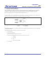
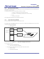
Example:
Table 1
Intruder Alarm Operation Description
Project :
An Intruder Alarm
Description :
When there is an intrusion (Port 30 detected low),
- A message will be sent out through the serial port.
- An Alarm/LED will be set and
The alarm/LED can be cleared via a switch.
LED /Alarm
From External
Port 30
Port 90
Sensor
To PC
SCI
Port 31
Disable
MCU
Switch
RS232 Driver
Figure 1
Table 2
Block Diagram of an intruder alarm
Port Usage of intruder alarm
Peripherals
Condition
Function
Port 30
Input
Intrusion detection
Port 31
Input
Disable switch
Port 90
Output
Alarm/LED
Serial Port 1
Asyn 9600 bps, 1 start, 8 data, 1 stop, No parity
Communicate Channel
-
Port 9 is used for driving LED as it has a large current drive (25mA) for the LED. If another port is used, a transistor driver
will be needed.
-
The example uses SLP H8/38024 as the controller. By invoking HEW project generation, the basic code structure, which
consists of all peripherals and ports definition, will be generated.
AN0403001/Rev.1.00
March 2004
Page 5 of 21
PRELIMINARY
HEW
Embedded C Programming II (ECProgramII)
-
HEW will generate
o
Reset routine.c
o
main() project.c
o
iodefine.h
Please refer the detail of HEW code generation in Application Note: “HEW Code Generation” or HEW user’s manual
-
2.2.1
-
In this example, only the main project C file will be modified.
Port and Peripheral Definition File
The following is extracted from the iodefine.h.
struct st_io {
…
…
union {
unsigned char BYTE;
struct {
unsigned char P37:1;
unsigned char P36:1;
unsigned char P35:1;
unsigned char P34:1;
unsigned char P33:1;
unsigned char P32:1;
unsigned char P31:1;
unsigned char P30:1;
} BIT;
} PDR3;
…
…
union {
unsigned char BYTE;
struct {
unsigned char :2;
unsigned char P95:1;
unsigned char P94:1;
unsigned char P93:1;
unsigned char P92:1;
unsigned char P91:1;
unsigned char P90:1;
} BIT;
} PDR9;
…
…
union {
unsigned char BYTE;
struct {
unsigned char PCR37:1;
unsigned char PCR36:1;
unsigned char PCR35:1;
unsigned char PCR34:1;
unsigned char PCR33:1;
unsigned char PCR32:1;
unsigned char PCR31:1;
unsigned char PCR30:1;
} BIT;
} PCR3;
AN0403001/Rev.1.00
/* struct I/O */
/* PDR3
/* Byte Access
/* Bit Access
/* P37
/* P36
/* P35
/* P34
/* P33
/* P32
/* P31
/* P30
/*
/*
*/
*/
*/
*/
*/
*/
*/
*/
*/
*/
*/
*/
*/
/* PDR9
/* Byte Access
/* Bit Access
/*
/* P95
/* P94
/* P93
/* P92
/* P91
/* P90
/*
/*
*/
*/
*/
*/
*/
*/
*/
*/
*/
*/
*/
*/
/* PCR3
/* Byte Access
/* Bit Access
/* PCR37
/* PCR36
/* PCR35
/* PCR34
/* PCR33
/* PCR32
/* PCR31
/* PCR30
/*
/*
*/
*/
*/
*/
*/
*/
*/
*/
*/
*/
*/
*/
*/
March 2004
Page 6 of 21
PRELIMINARY
HEW
Embedded C Programming II (ECProgramII)
…
…
union {
unsigned char BYTE;
struct {
unsigned char :4;
unsigned char PIOFF:1;
unsigned char :1;
unsigned char PWM2:1;
unsigned char PWM1:1;
} BIT;
} PMR9;
/* PMR9
/* Byte Access
/* Bit Access
/*
/* PIOFF
/*
/* PWM2
/* PWM1
/*
/*
…
…
};
/*
…
…
#define P_SCI3 (*(volatile struct st_sci3 *)0x0000FF91)
#define P_IO (*(volatile struct st_io *)0x0000FFC8)
…
…
*/
*/
*/
*/
*/
*/
*/
*/
*/
*/
*/
/* SCI3 Address
/* I/O Address
*/
*/
Observation
-
The structure/union declaration is based on the information provided in the MCU hardware user manual (Refer to Figure 1)
-
The “volatile “ keyword is used in the declaration for all the peripherals and ports.
-
The structure/union declaration will enable the use of “bit manipulation” assembly instruction.
AN0403001/Rev.1.00
March 2004
Page 7 of 21
PRELIMINARY
HEW
Embedded C Programming II (ECProgramII)
2.2.2
-
Initialization of Port
It is essential to initialize the hardware peripherals at power up state.
This routine can be called either in the reset routine (if it is critical to setup the peripherals early), or main routine.
HEW will generate a Hardware_Setup() function if this feature is enabled in the project generation.
o
-
In this example, a init_io() routine is written to:
Initialize the Port 3 and 9.
o
Table 3
Port Register
Name
Abbr.
R/W
Initial Value
Address
Port Data Register 9
PDR9
R/W
H’ FF
H’ FFDC
Port Mode Register 9
PMR9
R/W
-
H’ FFEC
void init_io(void)
{
// Setting for General Application
P_IO.PCR3.BYTE = 0x00;
P_IO.PUCR3.BYTE = 0x00;
//P37..P31 : inputs
//Turn off the MOS pull-up
//PMR3 : |AEVL|AEVH|---|---|---|TMOFH|TMOFL|---|
//AEVL = 0 : P37 as I/O
//AEVH = 0 : P36 as I/O
//TMOFH = 0: P32 as I/O
//TMOFL = 0: P31 as I/O
P_IO.PMR3.BYTE = 0x00;
//PMR9 : |---|---|---|---|PIOFF|---|PWM2|PWM1|
//PIOFF = 0 : large-current port step-up circuit is turned on
//PWM1 = PWM2 = 0 : P90 and P91 functions as P_IO output pin
P_IO.PMR9.BYTE = 0xF0;
set_imask_ccr(0);
}
AN0403001/Rev.1.00
March 2004
Page 8 of 21
PRELIMINARY
HEW
Embedded C Programming II (ECProgramII)
2.2.3
Initialization of Serial Port
The init_sci() routine is to initialize the Serial port. This routine can be integrated with the init_io() routine.
This function set the serial port to operate at Asynchronous mode at 9600 baud rate.
The following are the relevant registers for serial port initialization.
Table 4
Serial Port Register
Name
Abbr.
R/W
Initial Value
Address
Serial Mode Register
SMR
R/W
H’ 00
H’ FFA8
Bit Rate Register
BRR
R/W
H’ FF
H’ FFA9
Serial Control Register
SCR3
R/W
H’ 00
H’ FFAA
Transmit Data Register
TDR
R/W
H’ FF
H’ FFAB
Serial Status Register
SSR
R/W
H’ 84
H’ FFAC
Receive Data Register
RDR
R
H’ 00
H’ FFAD
Transmit Shift Register
TSR
Protected
-
-
Receive Shift Register
RSR
Protected
-
-
Bit Rate Counter
BRC
Protected
-
-
CKSTPR1
R/W
H’ FF
H’ FFFA
SPCR
R/W
H’ FF
H’ FF91
Clock Stop Register 1
Serial Port Control Register
void init_sci(void)
{
//SCR3 : |TIE|RIE|TE|RE|MPIE|TEIE|CKE1|CKE0|
//TIE : Transmit interrupt enable
//RIE : Receive interrupt enable
//TE : Transmit enable
//RE : Receive enable
//MPIE : Multiprocessor interrupt enable
//TEIE : Transmit end interrupt enable
//CKE1 = CKE0 = 0
//asynchronous mode, internal clock source, SCK32 functions as I/O port
P_SCI3.SCR3.BYTE = 0x30;
//SMR : |COM|CHR|PE|PM|STOP|MP|CKS1|CKS0| : |0|0|0|0|0|0|0|0|
//COM : Communication Mode : 0 : asynchronous mode
//CHR : Character Length : 0 : character length = 8 bits
//PE : Parity Enable
: 0 : parity bit addition and checking disabled
//PM : Parity Mode
: 0 : even parity (no effect since parity is already disabled)
//STOP: Stop Bit Length : 0 : 1 stop bit
//MP : Multiprocessor Mode : 0 : multiprocessor communication function disabled
//|CKS1|CKS0| : Clock Select: |0|0| : clock source for baud rate generator = clk
P_SCI3.SMR.BYTE = 0x00;
// Startup default to 9600bps
// n = 0
// N = 25
// for OSC = 16 MHz
P_SCI3.BRR = 25;
AN0403001/Rev.1.00
March 2004
Page 9 of 21
PRELIMINARY
HEW
Embedded C Programming II (ECProgramII)
//SPCR : |---|---|SPC32|---|SCINV3|SCINV2|---|---| : |1|1|1|0|0|0|0|0|
//SPC32 = 1 : P42 functions as TXD32 output pin
//need to set TE bit in SCR3 after setting this bit to 1
//SCINV3 = 0 : TXD32 output data is not inverted
//SCINV2= 0 : RXD32 input data is not inverted
//Bits 7 and 6 are reserved and always read as 1
//Bits 4, 1 and 0 are reserved and only 0 can be written to these bits
P_SCI3.SPCR.BYTE = 0xE0;
//SSR : |TDRE|RDRF|OER|FER|PER|TEND|MPBR|MPBT|
//TDRE : transmit data register empty
//RDRF : receive data register full
//OER : overrun error
//FER : framing error
//PER : parity error
//TEND : transmit end
//MPBR : Multiprocessor bit receive
//MPBT : Multiprocessor bit transfer
P_SCI3.SSR.BYTE = 0x84;
//Initialise upon reset to 0x84
}
In this peripheral initialization, calculation of the parameter is required.
-
N for BRR is calculated based on :
N
=
Where
OSC
(64 x 22n x B)
B:
N:
OSC:
n:
- 1
Bit rate (bit/s)
Baud rate generator BRR setting (0 ≤ N ≤ 255)
Value of ∅OSC (Hz)
Baud rate generator input clock number (n= 0, 2 or 3)
Table 5
SCI setting for N and n
OSC
10 MHz
Bit Rate
(bit/s)
110
150
200
250
300
600
1200
2400
4800
9600
19200
31250
AN0403001/Rev.1.00
n
2
2
2
2
0
0
0
N
88
64
48
38
129
64
4
16 MHz
Error
%
-0.25
0.16
-0.35
0.16
0.16
0.16
0
March 2004
n
2
2
2
2
2
2
0
0
0
0
0
0
N
141
103
77
64
51
25
207
103
51
25
12
7
Error
%
-.02
0.16
0.16
-0.79
0.16
0.16
0.16
0.16
0.16
0.16
0.16
0
Page 10 of 21
PRELIMINARY
HEW
Embedded C Programming II (ECProgramII)
2.2.4
Main Routine
The main routine is executed after the reset routine. The input/output port and serial port are initialized before the infinite loop is
entered. The program will check for intruder (Port 30) and switch (Port 31). Once condition is met, the respective action will be
executed.
<machine.h> is included, as the intrinsic function (set_imask_ccr()) is used.
#include "iodefine.h"
#include <machine.h>
void send_message(void);
void sci_charput(char OutputChar);
void init_sci(void);
void init_io(void);
void abort(void);
void main(void)
{
unsigned int delay;
init_io();
init_sci();
P_IO.PDR9.BYTE = 0xFF;
//Turn-off All LED
while(1)
{
if(!P_IO.PDR3.BIT.P30)
{
P_IO.PDR9.BIT.P92 = 0;
send_message();
}
//detected intrusion
//Turn-on alarm/LED
//call for help through serial port
if(!P_IO.PDR3.BIT.P31)
P_IO.PDR9.BIT.P92 = 1;
//clear alarm
//Turn-off alarm/LED
}
}
AN0403001/Rev.1.00
March 2004
Page 11 of 21
PRELIMINARY
HEW
Embedded C Programming II (ECProgramII)
2.2.5
Send Message
The following two routines are to send message in the form of “character”, to the external world via the serial port
void send_message(void)
{
sci_charput('H');
sci_charput('E');
sci_charput('L');
sci_charput('P');
sci_charput(' ');
}
void sci_charput(char OutputChar)
//Serial Port
{
while ((P_SCI3.SSR.BIT.TDRE) == 0);
P_SCI3.TDR = OutputChar;
P_SCI3.SSR.BIT.TDRE = 0;
}
The routine checks for the ready flag before it sends the variable “OutputChar” to the serial buffer.
2.2.6
Summary & Improvement
The program does not have many tasks. Therefore the polling method to check for the intruder and switch may not cause many
resources wastage. If too many tasks are executing, it may be wise to use interrupt to signify an intruder access. The sending of
message through the polling method is also taking up much CPU time. (The serial port is operating at 9600bps). The interrupt
method may be more efficient. In this example, the bouncing effect of the switch is ignored. The debouncing can be improved using
software mean by performing a double check.
AN0403001/Rev.1.00
March 2004
Page 12 of 21
PRELIMINARY
HEW
Embedded C Programming II (ECProgramII)
3.
Access of External Memory
For lower-end MCUs, such as the SLP, which have no external bus interface, usage of serial interface protocol to access external
memory will be preferred as this uses lesser pin count. The common memory used is I2C or SPI E2PROM. If such interface
peripheral is not available, programmer will need to write the algorithm based on the interface and memory specification.
Please refer to Application Note on “Interfacing to EEPROM with I2C Emulation”
For higher-end MCUs, such as the H8/300H, which is catered to support external memory, programmers will have to make several
settings in order to make this external memory work seamlessly with the main system coding.
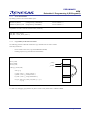
Figure 2
Area 3 Mapping
For the access of external memory, other than the physical hardware consideration, the following settings are to be considered when
accessing external memory.
(Physical hardware interface consideration is not discussed in this document)
1.
Section declaration
2.
Bus State Controller (BSC)
-
Must be initialized before the memory can be used.
-
The following are the key points to note when memory connection is concerned
i. Wait states
ii. Bus width
iii. Area
iv. Refresh cycle (For DRAM)
3.
Access Method
AN0403001/Rev.1.00
March 2004
Page 13 of 21
PRELIMINARY
HEW
Embedded C Programming II (ECProgramII)
3.1
Example
The following example illustrates the settings required to access the external memory:
Example:
Table 6
Area 3 Interface Information
Memory
ROM
Area
Area 3 of H8/3048 in advanced mode
H’60 0000 - H’7F FFFF
H8/3048
Address
External
Memory
Data
/RD
/WR
/CS3
Figure 3
3.1.1
MCU Interface to ROM
Section Declaration
The objective of setting the section is to notify the compiler that the relevant code and data are to be stored in a specific area. In this
case, the external memory is located at area 3.
Assuming that the external memory is a ROM, and a program section and a constant section are to be stored.
There are two steps to achieve this:
1.
In the project file:
Declare the section
#pragma section extmem
const char ExtData[] = "hello";
int total(int a, int b)
{
return (a+b);
}
#pragma section
In this case, Data “ExtData” and Function “total” are declared within the section “extmem”.
The Linker will look for Cextmem(Constant) and Pextmem(Program) section declarations.
NOTE: if other variables are declared, the linker will look for the respective sections.
AN0403001/Rev.1.00
March 2004
Page 14 of 21
PRELIMINARY
HEW
Embedded C Programming II (ECProgramII)
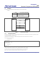
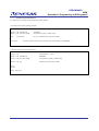
2.
In HEW section setting
Figure 4
HEW Section Setting
The section can be declared in the [Section] Category of the Link/Library tab.
-
Place the cursor at the [Address] Column and Click on [Add…] button.
o
-
Place the cursor at the [Section] Column and Click on [Add…] button.
o
-
Key in the Address: H’60 0000
Key in the section name: Pextmem
Place the cursor at the [Section] Column and Click on [Add…] button.
o
Key in the section name: Cextmem
The above steps will ensure that the compiled program will be located in the designated area.
To verify the output, the map file can be generated. ([List] Category of the Link/Library tab)
P
C$DSEC
C$BSEC
D
Pextmem
Cextmem
B
R
S
00000800
000008e2
000008ee
000008f6
00600000
00600004
00ffef10
00fff330
00fffd00
000008e1
000008ed
000008f5
000008f9
00600003
00600009
00fff32f
00fff333
00fffeff
Figure 5
AN0403001/Rev.1.00
e2
c
8
4
4
6
420
4
200
2
2
2
2
2
2
2
2
2
HEW Generated Map File
March 2004
Page 15 of 21
PRELIMINARY
HEW
Embedded C Programming II (ECProgramII)
3.1.2
Bus State Controller (BSC)
Both the hardware and linker must be set correctly. However, the access to the external memory may not be successful unless the bus
state controller is properly initialized.
The following are the key points to note when memory connection is concerned:
i. Wait states (1-5 Software wait states or hardware wait state)
ii. Bus width (8 or 16 bit depending on operating mode, access area, & setting)
iii. Area
iv. Refresh cycle (For DRAM)
These settings must match the hardware wiring and memory characteristic.
3.1.3
Code & Data Access Method
The current example has shown one example of external memory accessed.
The “extmem” section contain ROM based data and code. Thus users have to split their final compiled project into two parts in order
to program into the MCU & external ROM:
a.
H8/3048 internal ROM
b.
External ROM.
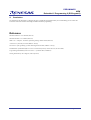
Main routine
- Internal ROM
H8/300H MCU
Memory Map
H8/300H MCU
External routine
- External ROM
2
E PROM
Figure 6
Illustration of Mapping & Physical device
The other possible scenarios are:
1.
Needs to access Data in external memory area
a.
2.
This can be a external ASIC containing data
MCU will copy the compiled code from one area to another area for faster execution
a.
EEPROM to DRAM
b.
Internal ROM to Internal RAM
AN0403001/Rev.1.00
March 2004
Page 16 of 21
PRELIMINARY
HEW
Embedded C Programming II (ECProgramII)
3.1.3.1
Access External Data
By making a pointer to the external address space:
#define EXT_DATA
#define EXT_DATA_PTR
(*(unsigned long *)0x0600000)
((unsigned long *)0x0600000)
/* Area 3 Address */
/* Area 3 Address */
Programmer can read or write the external memory seamlessly.
Read_data = EXT_DATA;
Read_data = *(EXT_DATA_PTR++);
3.1.3.2
Copy Memory from Section to Section
The following provides an alternative method to copy code/data from one area to another.
These may be done for:
-
Faster execution in an area (copy from E2PROM to DRAM)
-
Flashing purposes (copy from flash to internal RAM)
//Copy contents from section “Source” to section “Destination”
char *S_TOP;
char *S_END;
char *D_TOP;
__sectop
Source
__secend
void copy_section(void)
{
char *p, *q;
S_TOP = (char *)__sectop (“Source”);
S_END = (char *)__secend(“Source”);
D_TOP = (char *)__sectop(“Destination”);
Destination
for( p=S_TOP, q=D_TOP ; p<S_END ; p++, q++ )
*q= *p;
}
To enable easy debugging, programmers may like to use the overlay feature that is available in HEW.
AN0403001/Rev.1.00
March 2004
Page 17 of 21
PRELIMINARY
HEW
Embedded C Programming II (ECProgramII)
3.1.3.3
Execution of External Function
The following are examples of external function calling methods.
i. Function pointer with no passing parameter.
typedef
void
(*extFnPtr)(void);
#define EXT_ADDR_PTR
#define EXT_FN_PTR_ADDR
0x0600000
(unsigned long *)(EXT_ADDR_PTR)
static
Ext_Fn = (extFnPtr)(EXT_FN_PTR_ADDR)
const extFnPtr
…
(*Ext_Fn)();
…
// Call the external function, which is located in the external memory (0x06000000)
ii. Function pointer with passing parameters.
typedef
void
(*extFnPtr)(char *, char);
#define EXT_ADDR_PTR
#define EXT_FN_PTR_ADDR
0x0600000
*(unsigned long *)(EXT_ADDR_PTR)
#define
(extFnPtr)(EXT_FN_PTR_ADDR)
EXT_FN
…
char *p;
char var;
…
(*EXT_FN)(p, var);
…
AN0403001/Rev.1.00
March 2004
Page 18 of 21
PRELIMINARY
HEW
Embedded C Programming II (ECProgramII)
4.
Conclusion
The emphasis of this document is to illustrate the ports, peripherals and external memory access methodology. It also creates the
awareness of the basic hardware knowledge needed for firmware programming.
Reference
H8/38024 Hardware User Manual (Renesas)
H8/3048 Hardware User Manual (Renesas)
HEW C/C++ Compiler, Assembler, Optimizing Linkage Editor manual (Renesas)
A book on C by Al Kelley Ira Pohl (Addison –Wesley)
The Practice of Programming by Brain W.Kernighan & Rob Pike (Addison –Wesley)
Fundamentals of Embedded Software where C and Assembly Meet by Daniel W.Lewis (Prentice Hall)
Programming Embedded Systems in C and C++ by Michael Barr (O’REILLY)
Writing Solid Code by Steve Maguire (Microsoft Press)
AN0403001/Rev.1.00
March 2004
Page 19 of 21
PRELIMINARY
HEW
Embedded C Programming II (ECProgramII)
Revision Record
Description
Rev.
Date
Page
Summary
1.00
March 2004
—
First edition issued
AN0403001/Rev.1.00
March 2004
Page 20 of 21
PRELIMINARY
HEW
Embedded C Programming II (ECProgramII)
Keep safety first in your circuit designs!
1. Renesas Technology Corporation puts the maximum effort into making semiconductor products
better and more reliable, but there is always the possibility that trouble may occur with them. Trouble
with semiconductors may lead to personal injury, fire or property damage.
Remember to give due consideration to safety when making your circuit designs, with appropriate
measures such as (i) placement of substitutive, auxiliary circuits, (ii) use of nonflammable material or
(iii) prevention against any malfunction or mishap.
Notes regarding these materials
1. These materials are intended as a reference to assist our customers in the selection of the Renesas
Technology Corporation product best suited to the customer's application; they do not convey any
license under any intellectual property rights, or any other rights, belonging to Renesas Technology
Corporation or a third party.
2. Renesas Technology Corporation assumes no responsibility for any damage, or infringement of any
third-party's rights, originating in the use of any product data, diagrams, charts, programs,
algorithms, or circuit application examples contained in these materials.
3. All information contained in these materials, including product data, diagrams, charts, programs and
algorithms represents information on products at the time of publication of these materials, and are
subject to change by Renesas Technology Corporation without notice due to product improvements
or other reasons. It is therefore recommended that customers contact Renesas Technology
Corporation or an authorized Renesas Technology Corporation product distributor for the latest
product information before purchasing a product listed herein.
The information described here may contain technical inaccuracies or typographical errors.
Renesas Technology Corporation assumes no responsibility for any damage, liability, or other loss
rising from these inaccuracies or errors.
Please also pay attention to information published by Renesas Technology Corporation by various
means, including the Renesas Technology Corporation Semiconductor home page
(http://www.renesas.com).
4. When using any or all of the information contained in these materials, including product data,
diagrams, charts, programs, and algorithms, please be sure to evaluate all information as a total
system before making a final decision on the applicability of the information and products. Renesas
Technology Corporation assumes no responsibility for any damage, liability or other loss resulting
from the information contained herein.
5. Renesas Technology Corporation semiconductors are not designed or manufactured for use in a
device or system that is used under circumstances in which human life is potentially at stake.
Please contact Renesas Technology Corporation or an authorized Renesas Technology Corporation
product distributor when considering the use of a product contained herein for any specific
purposes, such as apparatus or systems for transportation, vehicular, medical, aerospace, nuclear,
or undersea repeater use.
6. The prior written approval of Renesas Technology Corporation is necessary to reprint or reproduce
in whole or in part these materials.
7. If these products or technologies are subject to the Japanese export control restrictions, they must
be exported under a license from the Japanese government and cannot be imported into a country
other than the approved destination.
Any diversion or reexport contrary to the export control laws and regulations of Japan and/or the
country of destination is prohibited.
8. Please contact Renesas Technology Corporation for further details on these materials or the
products contained therein.
AN0403001/Rev.1.00
March 2004
Page 21 of 21