1
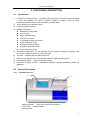
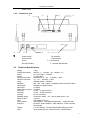
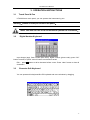
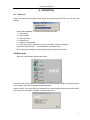
UT-6000 Microplate Reader User’s Manual PLEASE READ THIS MANUAL CAREFULLY BEFORE OPERATION 3, Hagavish st. Israel 58817 Tel: 972 3 5595252, Fax: 972 3 5594529 [email protected] MRC.8.15 1 UT-6000 User’s Manual CONTENTS SYMBOLS DESCRIPTION ................................................................................................................. 4 SAFETY PRECAUTIONS AND POTENTIAL HAZARDS.............................................................. 5 HOW TO USE THE MANUAL ............................................................................................................ 8 1. INSTALLATION................................................................................................................................ 9 1.1 1.2 1.3 1.4 UNPACKING .............................................................................................................................. 9 ENVIRONMENTAL REQUIREMENTS .......................................................................................... 9 ELECTRICAL SETUP............................................................................................................... 9 EXTERNAL PRINTER CONNECTION ....................................................................................... 10 2. FUNCTIONAL DESCRIPTION..................................................................................................... 11 2.1 INTRODUCTION.......................................................................................................................... 11 2.2 GENERAL DESCRIPTION ........................................................................................................... 11 2.2.1 UT-6000 front view ......................................................................................................... 11 2.2.2 UT-6000 rear view .......................................................................................................... 12 2.3 TECHNICAL SPECIFICATIONS .................................................................................................... 12 3. OPERATION INSTRUCTIONS ................................................................................................. 13 3.1 3.2 3.3 4. TOUCH PANEL & PEN .............................................................................................................. 13 DIGITAL NUMBER KEYBOARD ................................................................................................ 13 CHARACTER SOFT KEYBOARD ............................................................................................. 13 OPERATION................................................................................................................................ 14 4.1 POWER ON ............................................................................................................................. 14 4.2 MAIN MENU .................................................................................................................................. 14 5. PROGRAM .................................................................................................................................. 15 5.1 MODE SETTING ...................................................................................................................... 15 5.1.1 ABS mode .................................................................................................................... 15 5.1.2 Cut-Off mode ............................................................................................................... 15 5.1.3 Calculation mode......................................................................................................... 15 5.2 EDIT PROGRAM SETTING ...................................................................................................... 16 5.3 CREATING PROGRAM ............................................................................................................. 19 5.4 DELETING PROGRAM ............................................................................................................. 19 5.5 STANDARD ............................................................................................................................. 19 6. RUN THE TESTS ........................................................................................................................... 21 6.1 6.2 6.3 6.4 6.5 PLATE PARAMETERS SETTING .............................................................................................. 21 SELECT TEST PROGRAM ....................................................................................................... 21 MARK WELL............................................................................................................................ 22 SELECT ALL ........................................................................................................................... 23 CLEAR ALL ............................................................................................................................. 24 2 UT-6000 User’s Manual 6.6 6.7 6.8 6.9 6.10 TEST....................................................................................................................................... 24 RESULTS ................................................................................................................................ 24 CALCULATION RESULTS ........................................................................................................ 25 PRINTING ............................................................................................................................... 25 STORING TEST RESULTS....................................................................................................... 26 7. QC MANAGE .................................................................................................................................. 27 7.1 OPERATION.............................................................................................................................. 27 7.2 QC SET ...................................................................................................................................... 27 7.2.1 ELISA SET.............................................................................................................................. 27 7.2.2 IMMEDIATE SET ................................................................................................................... 27 7.2.3 CLEAR DATA OF THE CURRENT MONTH....................................................................... 28 7.3 QC SEARCH ............................................................................................................................. 28 7.3.1 OPERATION .......................................................................................................................... 28 7.3.2 QC FIGURE............................................................................................................................ 28 8. REPORT .......................................................................................................................................... 29 8.1 REPORT FORM............................................................................................................................. 29 8.2 REPORT BY PATIENT LIST ........................................................................................................... 29 8.2.1 Edit patient infomation ................................................................................................ 29 8.2.2 Preview report.............................................................................................................. 30 8.2.3 Delete patient data ...................................................................................................... 30 8.2.4 Print report.................................................................................................................... 30 8.3 PRINT BY PROGRAM LIST ...................................................................................................... 30 8.3.1 Preview report.............................................................................................................. 31 8.3.2 Delete program............................................................................................................ 31 8.3.3 Print report.................................................................................................................... 31 8.3.4 Gather print .................................................................................................................. 31 9. SYSTEM MANAGE........................................................................................................................ 33 9.1 SYSTEM SETTING ........................................................................................................................ 33 9.2 INFORMATION .............................................................................................................................. 34 9.3 SYSTEM LOG .............................................................................................................................. 35 9.4 COMMUNICATION TO PC............................................................................................................. 36 10. POWER OFF ................................................................................................................................ 37 11. INSTRUMENT SERVICE ............................................................................................................ 38 11.1 MAINTENANCE ....................................................................................................................... 38 11.2 CLEANING THE INSTRUMENT ................................................................................................ 38 11.3 CHANGING PART OF INSTRUMENT........................................................................................ 38 11.3.1 Changing the fuses ..................................................................................................... 38 11.3.2 Changing the lamp ...................................................................................................... 38 11.4 TROUBLESHOOTING .............................................................................................................. 39 3 UT-6000 User’s Manual Symbols description Symbols in the manual NOTE! Notes contain additional information or tips when using the instrument. ATTENTION! Cautions Cautions should be followed carefully to ensure your instrument work correctly and to avoid unnecessary personal injury. Symbols on the instrument This symbol means that the labeled item is hot while the instrument is in use. Don’t touch the labeled item as you could be burnt. The symbol is labeled on the lamp support of optic system. This means that the labeled item could lead to personal injury and/or damage to the reader. The symbol is labeled beside the power outlet and some external interface. The symbols for “SERIAL NUMBER”, The serial number shall be after or below the symbol, adjacent to it The symbol means the product is in vitro diagnostic medical device. The symbol indicates the manufacturer and its address, after which are shown its name and address. The symbol indicates EU representatives of the manufacturer and their addresses, after which are shown their names and addresses. The symbol indicates biological pollution, marked in the part where the instrument contacts the clinical reagent. The symbol appears in black side and yellow background. The symbol indicates temperature range of the analyzers during storage and transportation. 4 UT-6000 User’s Manual Safety Precautions and Potential Hazards General Before you start installing and working with the reader, you should read the safety precautions and regulations shown in this chapter. Operator Qualification Please note that the operation with Microplate Reader should be carried out only by the doctor or clinical inspector who has undergone necessary training provided by the sales agent. Service Technician Qualification To install, maintain and repair the instrument, a service technician has to be trained on the instrument by the manufacturer or their representative. A service technician is also expected to be familiar with the normal operation of the instrument as described in the User’s manual and the special operations as described in the service manual. Electrical To use analyser safely, pay attention to the following items: To prevent the risk of electrical shock and/or damage to the instrument, Operator should not open the cover of the instrument. Only authorized personnel, for example, service technicians, may open the instrument to perform maintenance or repair. Touching the main board when the power is on may cause severe injury or death. Any problem, please ask for helps from your supplier. Mechanical There is no risk presented by the mechanical parts of the instrument when the instrument is closed. If the covers of the instruments are removed, mechanical parts could cause personal injury or the instrument may be damaged if the following advice is not being considered: DO NOT wear loose garments or jewellery that could catch in mechanisms. DO NOT put your fingers/hands into the pathway or any part while the instrument is in operation. DO NOT attempt mechanical repair unless the instrument is not in operation or OFF. Lamp The source lamp becomes extremely hot during operation; never touch the lamp when it is on! If the lamp needs to be changed, always switch off the lamp by switching off the instrument and then wait until the lamp has cooled down. 5 UT-6000 User’s Manual Chemical The operator is responsible for taking all necessary precautions against hazards associated with the use of clinical laboratory chemicals. Specific recommendations for each reagent used with the Reader are normally found on the manufacturer’s package inserts or the on the product information sheets for each chemical. Wipe up any reagent spillage on the instrument immediately. Biohazardous Materials As with all vitro diagnostic equipment, patient samples that are assayed on this system, as well as all waste from the waste container, should be treated as the potentially biohasardous. All materials and mechanical components associated with the sampling and waste system should be handled according to your facility’s biohazard procedure. Use the personal protective equipment recommended by your facility when handling any of these components. Detailed recommendations: - Samples Treat all samples as potentially biohaazardous and infectious. If any sample is spit on the instrument, utilize the correct personal protective equipment (PPE- gloves, lab coat, etc...), wipe it up immediately and clean the contaminated with a disinfectant. - Waste solutions and solid wastes Avoid direct contact with waste solution and/or solid waste. Both should be handled as potentially biohazardous. Dispose of waste solution and/or solid waste according to the relevant governmental regulations. Consult the reagent manufacturer for information on the concentrations of heavy metals and other toxic constituents in each reagent. - Biohazardous parts Avoid direct contact with the micropplate. Treat these parts as potentially biohazardous and /or infectious - Reagents Avoid direct body-contact with reagents. Direct body-contact may result in irritation or damage to your skin. Refer to the manufacturer’s reagent kit box and package inserts, or product information sheets for specific instructions. 6 UT-6000 User’s Manual Avoid direct body-contact with cleaning solution. Direct body-contact amy result in skin irritation or damage. Refer to the manufacturer’s kit box and package inserts, or product information sheets for specific instructions. Additional Precautions - Flammables Avoid using dangerous flammable material around the instrument. - Accuracy/Precision of the Measured Results For proper use of the instrument, measure control samples and monitor the instrument during the operation. An incorrectly measured result may lead to an error in diagnosis, thereby posing a danger to the patient. Treat all reagents according to the manufacturer’s recommendations. Refer to the reagent kit box and package inserts, or product information sheets for specific instructions. Make sure that the sample/reagent mixture does not contain any blood clots, dust or other insoluble contaminants. If insoluble contaminants are contained in the sample, correct measuring values may not be obtained. - Application The instrument is designed for clinical ELISA test analysis using water-soluble samples and reagents. Please note that other types of analysis may not be applicable to the instrument. - Operation and Maintenance During operation and maintenance of the instrument, proceed according to the instructors and do not touch any parts of the instrument other than those specified. Never leave a Reagents/sample mixture in the microplate for longer than necessary. Always clean the microplate after a batch of measurement and keep the microplate cleanliness when not in use. Verify the front covers closed while the instrument in operation. Avoid touching the mechanism, such as the sipper mechanism inside the instrument, while the instrument is operating. This may cause operation stop or damage the instrument. 7 UT-6000 User’s Manual How to use the manual Thank you to be the user of UT-6000. This manual is a user’s guide for UT-6000 Microplate Reader. It contents system installation, operating procedures, system parameters setting and maintenance, and so on. We suggest that the user read the manual carefully before user operates this device. If you have any question, you can contact with Local distributor. The instruments with different versions or collocations will have some differences in functions Note: Contain useful tips on using your instrument. They appear in italicized type. Cautions: cautions should be followed carefully to ensure your instrument operates correctly and is not damaged. Cautions appear in bold type like this. 8 UT-6000 User’s Manual 1. INSTALLATION 1.1 Unpacking Unpack UT-6000 carefully and check for any damage that may have been caused during transportation. check the components:: UT-6000 instrument Operator’s manual Packing list Guarantee Accessories:panel pen,power cable,print cable,RS-232 serial cable,pstn line,lamp, fuses Keep the original package for future transportation Note! report representative。 1.2 any damage or missing to your local Environmental Requirements Locate UT-6000 to avoid exposure to excess dust, vibrations, strong magnetic fields, direct sunlight, draft, excessive moisture or large temperature fluctuations. Leave sufficient clearance (10 cm) at both sides of the unit for adequate air circulation. Note! instrument be operated within an ambient temperature range of 0 -40 and humidity≤85%。 1.3 Electrical Setup Power requirements a.c.110V ~220V 50 /60Hz 120W Attention! Cautions Ac power plug must be grounded at the main socket. The circuit used should be substantially free of large voltage transients such as large pumps, large centrifuges etc. If found smog, strange sound in instrument, please turn instrument off immediately and contact your dealer Connect the supplied power cable to the rear of the instrument as shown. Plug the other end of the power cable into an AC outlet. 9 UT-6000 User’s Manual 1.4 External Printer Connection With both the instrument and the external printer off, connect the parallel cable to the rear of the instrument. Plug the other end of the parallel cable into the printer. Then plug power cable into printer. Install printer paper if needed. 10 UT-6000 User’s Manual 2. FUNCTIONAL DESCRIPTION 2.1 1) 2) 3) 4) 5) 6) 7) 8) 9) Introduction UT-6000 is a microprocessor –controlled, general purpose photometer system designed to read and calculate the result of assays, including contagion, tumorous mark, hemopathy, dyshormonism, which are read in microtiter plate. Touch panel let your operation easily. 100 pre-programmed tests. Multiple calculations: Absorbance mode (ABS) Cut-Off mode Single standard mode Point to point mode % Absorbance Multi-Point Mode Linear regression mode Exponent regression mode Logarithm regression mode Power regression mode visualization mark plate,you can set blank, control, sample ,standard in any place,and run mostly 12 different tests in one 96 microplate. Test time <5s/plate,and mix plate before test Max save 100 program and 1000 patients’ data and 10000 sample records. generalization report ,support multi-type printers. information manage function:Department database, operator database, system log database. 2.2 2.2.1 General Description UT-6000 front view ② ① ③ ④ power pilot lamp: It light when opens the instrument touch panel: display program Internal printer 11 UT-6000 User’s Manual Plastic cover 2.2.2 UT-6000 rear view ④ ① P E IN L P O R E W F /O N R E T IN R 2 S ⑥ ⑤ ③ ② ⑦ ⑧ 3 2 T U P IN C A ① ② ③ ④ ⑤ ⑥ Power switch Power sokect Fuses RS-232 interface 2.3 SD interface USB interface ⑦ LAN interface ⑧ Contrast adjust button Technical Specifications Weight: Overall dimensions: Power: Fuses: Work Environment: Store Environment: Lamp: Standard Wavelength: Abs range: Measurement range: Accuracy: Precision: Linearity: Reading speed: Warm up time: CPU: Store content: Interface: Display: Input: 7.5kg 455mm(L)×330mm(W)×200mm(H) a.c.110V~220V,50-60Hz T3.15AL250V temperature 10 -40 ;Humidity ≤85% -10 -40 ;Humidity ≤85% OSRAM 64255,6V/20W, 405,450,492,630nm,(substitute filters from 400-700nm available on special order) 0-3.500A 0-2.000A 0-2.0A:±1.0%or±0.007A 0-2.0A:±0.5%or±0.005A ±2.0% or±0.007A Continuous mode <5s,step by step mode<15s 1 minute Embedded RISC cpu 100 program,1000 patient information,10000 test data RS-232C serial interface, USB interface,RJ45 interface, SD interface 5.7″LCD display(320×240 discernibility,256 gray scale) Touch panel and pen, external mouse(special order) 12 UT-6000 User’s Manual 3. OPERATION INSTRUCTIONS 3.1 Touch Panel & Pen UT-6000 has a touch panel; you can operator the instrument by pen. warning:please use the pen to touch the panel。 Note! You also can use a RS-232 mouse to operate the instrument。 3.2 Digital Number Keyboard Input integer (age), float number (abs value), digital number (phone code), press “OK” button to saved, or press “cancel” button to exit and no saved. Edit :press ← button to del a character before cursor. Press “clear” button to clear all characters. 3.3 Character Soft Keyboard You can operator this keyboard like PC keyboard and move windows by dragging. 13 UT-6000 User’s Manual 4. OPERATION 4.1 Power on Switch the instrument on using power switch and wait several seconds, you will see such display: During the initialization, UT-6000 will complete some task: 1) load system 2) check system 3) read user data 4) initialize front 5) waiting for lamp stable 6) check the circuit of light(in the course of checking ,the filter will rotate) instrument will self-check ,and initialization data will be load Error report will be display if the instrument has not pass the self-check. 4.2 Main menu After self-check,system display main menu: The main menu is the entrance to all operation for this instrument. When user clicks the icon in the window, the relative operation will be performed. Whe the “MRC” icon at the right, the information of version and authority about system will be found. After the exit button is clicked, system will be return. 14 UT-6000 User’s Manual 5. Program Press “program” icon, program list will be displayed: You can pre-program 100 tests in UT-6000. 5.1 Mode setting UT-6000 supports 10 calculation modes. They can be divided three types: 5.1.1 ABS mode UT-6000 only display and print out absorbance of samples by this mode. 5.1.2 Cut-Off mode Cut-Off formula: Cov X NC Y PC Fac In this cut-off mode, where NC is the mean of the negative controls, PC is the mean of the positive controls, Cov is the cutoff absorbance .X, Y, Fac are coefficients that have any positive and negative numerical value (including 0 and 1) e.g. sample OD/NC≥2.1 is positive, that X=2.1, Y=0, Fac=0. In regular cutoff mode, UT-6000 award that sample is positive if sample OD/Cov>1. 5.1.3 1) Calculation mode Single standard mode:A single calibrator material of known concentration is used so that concentrations of unknown samples may be calculated according to Beer’s Law. Abs Conc. 2) point to point mode:you can set 2-8 standards,the resulting calibrator curve is a series of lines connecting the calibrator points, which may be entered in ascending or descending order of absorbance. 15 UT-6000 User’s Manual Abs 3) 4) Abs Conc. Conc. %ABS: You can set 2-8 standards. The highest absorbance standard will be assigned a value of 100, and each sample and standard is reported as a percent of the absorbance of the highest calibrator. The resulting calibrator curve is a series of lines connecting the calibrator points, which may be entered in ascending or descending order of absorbance. Linear regression mode: You can set 2-8 standards. This is a multi-point standard mode that calculates a best fit linear equation based upon the standard points. Equations: Y kX b :This is used when the absorbance and the concentration is linear. Abs Conc. 5) Index regression mode: You can set 2-8 standards. Equation: Y ke bX ; This is used when the natural log of the absorbance is plotted against the concentration. 6) Logarithm regression mode: you can set 2-8 standards. Equation: Y kLnX b ; This is used when the natural log of the concentration is plotted against the absorbance 7) Exponent regression mode: You can set 2-8 standards. Equation: Y kX ; This is used b when the natural log of the absorbance is plotted against the natural log of the concentration. 8) Percent logarithm mode: You can set 4-8 standards. By these standards a new curve can be drawed, and then you can look it as a standard curve. By regression means the sample concentration will be got. 5.2 Edit Program Setting Select existed program (it will be marked), press “Edit” button, and display the following windows: 16 UT-6000 User’s Manual Program:program name, don’t input the name existed. Reagent:Input reagent name, you can ignore it. Wavelength Calibration mode Double sample:If select it, samples must be pipetted into consecutive two wells, the mean absorbance reading will be used to calculate a single concentration. Blank :You can set range of the blank abs. If blank absorbance out of range, system will display: “blank abs is out of range.” You can press >> button,come to next windows, or press << button,come back this windows, you can press “cancel” button, exit program configuration windows. 1) Standards mode setting windows: Standard number: you can select up to 8。 Concentration unit: you can select it from listing. Double standards: if select it, standards must be pipetted into consecutive two wells, the mean absorbance reading will be used to calculate a single concentration Standard conc. : double point standard conc. Listing, you can input standard concentration. 17 UT-6000 User’s Manual Notice: Standards may be entered in ascending order of absorbance. Standard 1 is the lowest concentration. 2) Cut-Off mode setting windows: Cut-Off formula parameter:Cov=X*N+Y*P+Fac. (Please see section 5.1.3) Range of Negative and positive: if absorbance of negative control and positive control is out of range, UT-6000 calculates as min or max abs. Double of controls: if select this, controls must be pipetted into consecutive two wells, the mean absorbance reading will be used to calculate a single concentration 3) Positive and negative setting windows 18 UT-6000 User’s Manual Qualitative mode: In this option you can select regular cov, reverse cov, none. Regular cov: Samples with values higher than the positive cutoff are labeled as positive. Sample with values lower than the negative cutoff are labeled as negative. Any samples with values falling between the negative cutoff and the positive cutoff are labeled as equivocal. Reverse cov: Samples with values lower than the positive cutoff are labeled as positive. Sample with values higher than the negative cutoff are labeled as negative. None: you can select none if you don’t award negative or positive. Normal range: please input the values with reagent instruction Press “Finished” button, come back program listing windows. 5.3 Creating program Press “new” button to create a new program, and then input the parameters. If the program name has existed, system will warn: “program exists.” 5.4 Deleting program Select one program in program listing, press “delete” button, system display windows: Press “Yes” button to delete program. Press “NO” button to cancel. 5.5 Standard Standard test results and curve will be stored. Operator can review and print the results. Select one program in program listing, Press “standard” button, system display standard conc. and abs. 19 UT-6000 User’s Manual Press “curve” button, system will display standard curve: Press “print” button, system will print standard curve. Note! Old standards will be deleted if modifying program setting. (Wavelength, calculate mode, standard number, standard conc.etc.) 20 UT-6000 User’s Manual 6. RUN THE TESTS 6.1 Plate Parameters Setting Press “test” icon in main menu, pop up such windows: Plate direction: A-H direction and 1-12 direction. Test mode: You can select continue mode(<5 seconds= or step mode (<15 seconds =。 Mixer setting: Mixer speed: you can select fast, normal, slow or none. Mixer time: you can select 1-60 seconds. Press “Ok” button, come to next windows: 6.2 Select Test Program UT-6000 support 12 programs in one plate, first press “New” button, the following windows display: select the program,press “OK” button. 21 UT-6000 User’s Manual Note! If you test multi-programs in one plate, you must set the programs one by one. STD: standard 6.3 Mark well You can set each well’s function. Select well’s function firstly, and click the well which you will mark. mark label: sample:1–999 blank:B negative controls:NC positive controls:PC standard:S1–S8 Quality Control:QC 6.3.1 Sample Click the well which will be tested, then the well will be marked .If you modify sample No., please click that well again. A windows display: Input sample No.again.If you input No. already exist, system display “sample NO. Already exist, input again.” Note! One patient is marked by only one sample NO. In one day. Negative controls: NC; Positive controls: PC 22 UT-6000 User’s Manual 6.3.2 Blank You can select blank well or no in different program. One program only set a blank well. Old blank value will be saved automatically and be used. 6.3.3 Negative controls You must set one negative control in one program other than negative control factor is 0. 6.3.4 Positive controls You can see negative control setting. (Section) 6.3.5 Standard This option is valid only when one program needs standards. If this program has old standards values, you can select set standards or not. Note! If one program set standards and test good,new values of standards will cover old values. 6.3.6 Clear If you want delete marked wells, press “clear” button, then point wells that what you want. 6.4 Select All Use this button; you can quickly mark the sample wells. Press “select all” button, display such windows: input start number(1-999)and start well(row number and line number),press “Ok” button. All wells in this plate will be marked samples. Start No. is that you input. In this option all set program and wells will be deleted. You should set standards and controls after “select all”. 23 UT-6000 User’s Manual 6.5 Clear All Press “Clear all” button, system display: Press “yes” button, clear all well setting. 6.6 Test Press “start” button, system will test the plate: You can press “stop” button to stop the test. 6.7 Results The test results will be displayed: 1-6 columns abs results will be displayed, press 7-12>> button, windows will display 7-12 columns abs results. Sample: 001 is sample number, 0.040 is abs results. 24 UT-6000 User’s Manual Note! if abs results> 3.500A,will display 3.500*,and calculate by 3.500,if abs<0.000A,display 0.000*,and calculation by 0.000. you can modify the well result by click the well: Input abs value and press “ok” button. Note! Standard or control abs change will affect all results in this program! 6.8 Calculation Results Press “result” button in abs result windows, display calibration results: You can see the values and negative/positive mark display in every well. If the values in some well <0.0, “*” will be labeled to this well. 6.9 Printing Note! QTA: quantitative analysis QLA: qualitative analysis Press “Print” button in testing windows, UT-6000 will print all test results. 25 UT-6000 User’s Manual 6.10 Storing Test Results Press “cancel” button in Abs windows, the instrument will automatically store the test results in history database. 26 UT-6000 User’s Manual 7. QC MANAGE 7.1 OPERATION Press “QC Manage” in main menu, system displays such windows: Now QC set and QC search function will be introduced. 7.2 QC SET At first you can select one program in the program list, and then select a way about quality control. The next step is to input the number of quality control, and press the “OK” button to memory your setting. 7.2.1 ELISA SET The way of ELISA has four kinds of condition to estimate the quality control data controlled or not. Of course, you can select one condition or more. 7.2.2 IMMEDIATE SET Select the immediate button and the data of QC test will be estimate by the immediate way. Note! When the way of quality control is changed, you must clear the data of quality control. Otherwise the estimation of quality control will be invalid. 27 UT-6000 User’s Manual 7.2.3 CLEAR DATA OF THE CURRENT MONTH Press the “Clear current QC data” button, the all data of current month will be deleted. 7.3 QC SEARCH 7.3.1 OPERATION Select the searched month from the month list and select the program. Then the relative figure of quality control will be displayed in the windows. Select the searched month from the month list and select the program. Then press “Send QC Data”, you can send the QC data of the selected month about the selected program to PC. Note! If QC test doesn’t set in the selected month, the figure of quality control will be empty in the month. If you want to get the figure, you must set the way of quality control and quarantee the program number is identical. 7.3.2 QC FIGURE Press the “Printer” button, the figure of quality control can be printed. 28 UT-6000 User’s Manual 8. REPORT 8.1 Report form Press “Report” in main menu, system displays such windows: Select report form: Report form: report by patient list or program list. Date range: today and all of days. 8.2 Report By Patient list Select “patient ”,press Ok button, display following windows: 1) 2) Select one patient Mark multi-patients:You can mark all patients by pointing first line in the title bar. 8.2.1 Edit patient infomation Select one patient, press “Edit” button, patient’s information windows pop up: 29 UT-6000 User’s Manual Input the information. Press “Ok” button to save information, press “cancel” button to exit without save. 8.2.2 Preview report Select a patient, press “preview” button, that patient‘s data display in list. 8.2.3 Delete patient data Press “delete” button, window pops up: Press “yes” button, all marked patient data will be delete. Press “no” button, exit without save. 8.2.4 Print report Press “print” button, all marked patient report will be print. 8.3 Print By Program list Select “program”, press “ok” button, and pop up program list windows: 30 UT-6000 User’s Manual 8.3.1 Preview report Select one program, press “preview” button, and pop up preview windows: 8.3.2 Delete program Press “delete” button and “yes” button,all marked program and test data will be delete. 8.3.3 Print report Press “print” button, all marked program’s standard curve and test data will be print. 8.3.4 Gather print UT-6000 support gather print, you can quickly print all negative or positive patient data in one day. Press “gather” button, come to next windows: Input date, select program and results from list, press “OK” button, all patients coincidence condition display in listing windows: 31 UT-6000 User’s Manual Press “print” button, all data will be printed. 32 UT-6000 User’s Manual 9. System Manage Click “System” icon in main menu, the following windows will be displayed: 9.1 System setting Press “sys. set” button in the above windows, the following windows will be displayed: 1) 2) 3) 4) Serial NO Hospital: hospital name. Date and time Printer: UT-6000 supports printers: Internal printer, PCL laser series, Epson ME 1+, and HP P1007. You can choose one of printers Note! Printers might be changed. Please reference to printer list of system setting. If printer setting is wrong, maybe printer works error. 5) 6) 7) Contrast adjust:press + button to increase contrast,press - button to decrease contrast. New value will be saved and used. Sound switching:Turn on or off the speaker Touch panel calibration : You can calibration touch panel. Press “touch panel ” button, come to calibration windows: 33 UT-6000 User’s Manual Press the cross center by pen, wait one second, the cross moves to next place automatically. You should continue press cross with pen again. The same operation repeats 5 times, system will display next windows: Note! The cross doesn’t move after pressing it. Please try it again. Please click anywhere in the panel, system will save new setting and come back system setting windows. 9.2 Information Press “Information” button in System windows, come to the following windows: 34 UT-6000 User’s Manual UT-6000 has an operator database and department database. You can add or delete operators/department in those databases. UT-6000 can store 100 records in those two databases. Select operator or department. For example operator database: add record :input operator name in the edit and press “add” button. If this operator’s name already exists, system will display windows: If database reach high range, system will report, “operator’s record is over.” 8) Deltree record:Select one operator in operators listing, press “Delete” button: Press “Yes” button to deltree that record, press “No” button to cancel. 9.3 System log Press “sys. log” button in System windows, you can view history log: 35 UT-6000 User’s Manual System log contain date, time, type and event status. UT-6000 can record max 2500 events. Last event arrange firstly. You can press “Clear” button to deltree all event records. Press “Cancel” button to come back main menu. 9.4 Communication to PC UT-6000 can connect to pc, send data to pc.With software, you can store patient lists, see curves, print reports, and collect QC data. For more information regarding pc software, contact your dealer. 1) Turn UT-6000 and pc, connect serial cable to UT-6000, and plug another end in pc COM1. Attention! Cautions UT-6000 and PC don’t open when connecting serial port, otherwise hardware will be wrong. 2) Run pc software, select data send menu, receive data. 3) Press “Data send” button in instrument, come to next windows,and press “Start” buton to send: 4) Sending data finished, press “Cancel” button to come back main menu. 36 UT-6000 User’s Manual 10. POWER OFF Press “Power off” button in main menu, display such windows: Press “yes” button, instrument will be turned off. Press “no” button, exit to main menu. Note! If don’t turn off instrument normally, results and parameters edit in this time will not be save. System will display such windows: Attention! Cautions UT-6000 and PC don’t open when connecting serial port, otherwise hardware will be wrong.Please keep power when turn instrument off. The instrument may fail to operate normally if the power is interrupted. When data saved, such windows will display: Now you can turn the power switch off safely. Notie! Turn UT-6000 off for at least 30 seconds and turn it on again. 37 UT-6000 User’s Manual 11. INSTRUMENT SERVICE 11.1 Maintenance UT-6000 is designed to be a maintenance free instrument. To insure optimum trouble free performance, the instrument should be kept dry and operated in an area free from excessive dust. 11.2 Cleaning The Instrument Keep working environment clean Use a slightly damp soft cloth to remove dirt or spills. For decontamination, 70% isopropanol is recommended. Use soft cloth to remove dirt or spills in LCD. Note! Use other chemicals or abrasive cleaners are not recommended. 11.3 Changing Part Of Instrument 11.3.1 Changing the fuses 1) 2) 3) Disconnect power cord from mains supply before replacing fuses. Open fuses box left in power, change fuses, close fuse box. Fuse specification:250V/3.15A. Turn the instrument on. Note! Use the same fuse for replacing. 11.3.2 Changing the lamp 1) Turn the instrument off,open instrument cover by unscrewing the one screw on the front of the instrument. 2) Remove four screws of the optical assembly cover. Remove the cover. 3) Lift up the lamp with the terminal socket. Pull the terminal socket from the lamp contacts. 4) Refit the terminal socket to the contacts of the new lamp(OSRAM64607,6V/20W).Place the new lamp in its place. 5) Close the optical assembly cover. Replace the screws. 6) Close the instrument cover. Turn UT-6000 on again. 38 UT-6000 User’s Manual 11.4 Troubleshooting Symptom Causes and Remedies UT-6000 does not Turn on Check power supply cord Check fuses Check power voltage Turn UT-6000 off for 30 seconds and turn it back on. Lamp does not light Check lamp Voltage Lamp is bad Change lamp RAM check error Turn UT-6000 off for 30 seconds and turn it back on. Firstly turn UT-6000 on and secondly turn printer on. Cable connect error, turn UT-6000 off, open instrument cover, and reconnect cable between two pcb. Lamp is too high Filters install in wrong place. Lamp is too low Lamp is bad and changes it. Motor does not work Motor is bad Open the cover of the instrument, check motor. Chopper wheel run faster Chopper driver motor error Open the cover of the instrument, check chopper driver motor. Filter does not come back zero place Filter wheel error. Open the cover of the instrument, check sensor. Plate does not come back original place The plate may be does not place in right place. Plate don’t move Driver Motor error, open cover, checks driver motor work or not. Open COM port error Maybe use serial mouse. Turn UT-6000 off. Disconnect the mouse from instrument and turn on it again. Printer don’t work Printer power works error. Check ON/OFF button in printer. Check printer type in system setting right or not. Firstly turn UT-6000 on then turn printer on. Check printer cable connect UT-6000 right or not. The printing is dim or incomplete Change ink box, clean printer head. The printing is jam See printer user manual Other printer error See printer user manual Note! For more information regarding service, contact you dealer. 39