Download This Manual gives you the information needed to :
Transcript
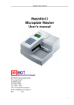
RT-2600C User’s Manual
RT-2600C
Microplate Washer
User’s Manual
Copyright:
Address:
Website:
Rev:
Rayto Life and Analytical Sciences Co., Ltd.
A/6F, Technology Building, Industrial Road, Shekou, Shenzhen, China
www.rayto.com
3.5e
RT-2600C User’s Manual
CONTENTS
SYMBOLS DESCRIPTION...................................................................................................... 1
SAFETY PRECAUTIONS AND POTENTIAL HAZARDS ................................................... 2
ADDITIONAL PRECAUTIONS................................................................................................ 3
1. GENERAL INFORMATION............................................................................................... 4
1.1.
1.2.
1.3.
1.4.
How to use this manual ......................................................................................................... 4
Copyright.................................................................................................................................. 5
Property of ............................................................................................................................... 6
Warranty .................................................................................................................................. 7
2. USE AND FUNCTION ....................................................................................................... 8
2.1.
2.2.
2.3.
2.4.
Name and intended use ........................................................................................................ 8
Product Features .................................................................................................................... 8
Specifications .......................................................................................................................... 9
System Description .............................................................................................................. 10
2.4.1.
Hardware Components....................................................................................................................... 10
3. INSTALLATION................................................................................................................. 12
3.1.
3.2.
3.3.
3.4.
3.5.
Unpacking.............................................................................................................................. 12
Installing the Wash Bottle.................................................................................................... 12
Installing the Waste Bottle................................................................................................... 13
Installing the dispensing head ............................................................................................ 13
Turn on the system............................................................................................................... 13
4. OPERATION ..................................................................................................................... 14
4.1.
4.2.
Function description ............................................................................................................. 14
4.1.1.
Keyboard .............................................................................................................................................. 14
4.1.2.
Dispense............................................................................................................................................... 15
4.1.3.
Aspiration.............................................................................................................................................. 16
4.1.4.
Start the programmer.......................................................................................................................... 17
System settings..................................................................................................................... 19
4.2.1.
Adjusting Contrast ............................................................................................................................... 19
4.2.2.
Changing Wash-Head ........................................................................................................................ 19
4.2.3.
Changing Plate .................................................................................................................................... 20
4.2.4.
Adjusting Wash-Head ......................................................................................................................... 20
4.2.5.
Adjust the horizontal of the wash-head ............................................................................................ 21
4.2.6.
Adjusting Top Aspiration .................................................................................................................... 21
4.2.7.
Adjusting Pump.................................................................................................................................... 22
5. MAINTENANCE AND CLEANING................................................................................. 23
5.1.
5.2.
5.3.
5.4.
Daily maintenance of worktable ......................................................................................... 23
Maintenance of dispensing head ....................................................................................... 23
Waste bottle treatment......................................................................................................... 24
Maintenance of the wash bottle.......................................................................................... 24
6. TROUBLESHOOTING .................................................................................................... 25
RT-2600C User’s Manual
SYMBOLS DESCRIPTION
Symbols in the manual
NOTE!
Notes contain additional information or tips when using the instrument.
ATTENTION! Cautions
Cautions should be followed carefully to ensure your instrument work
correctly and to avoid unnecessary personal injury.
Symbols on the instrument
This means that the labeled item could lead to personal injury and/or damage to
the analyzer.
The symbol is labeled beside the power outlet and some external interface.
The symbols for “SERIAL NUMBER”, the serial number shall be after or below the
symbol, adjacent to it
The symbol means the product is in vitro diagnostic medical device.
1
RT-2600C User’s Manual
SAFETY PRECAUTIONS AND POTENTIAL HAZARDS
General
Before you start installing and working with the washer, you should read the safety precautions and
regulations shown in this chapter.
Operator Qualification
Please note that the operation with Microplate Washer should be carried out only by the doctor or
clinical inspectors who have undergone necessary training provided by the sales agent.
Service Technician Qualification
To install, maintain and repair the instrument, a service technician has to be trained on the
instrument by the manufacturer or their representative. A service technician is also expected to be
familiar with the normal operation of the instrument as described in the User’s manual and the
special operations as described in the service manual.
Electrical
To use washer safely, pay attention to the following items:
To prevent the risk of electrical shock and/or damage to the instrument Operator should not open
the cover of the instrument. Only authorized personnel, for example, service technicians, may
open the instrument to perform maintenance or repair.
Touching the main board when the power is on may cause severe injury or death. Any problem,
please ask for helps from your supplier.
Mechanical
There is no risk presented by the mechanical parts of the instrument when the instrument is closed.
If the covers of the instruments are removed, mechanical parts could cause personal injury or the
instrument may be damaged if the following advice is not being considered:
DO NOT wear loose garments or jewellery that could catch in mechanisms.
DO NOT put your fingers/hands into the pathway or any part while the instrument is in operation.
DO NOT attempt mechanical repair unless the instrument is not in operation or OFF.
Waste bottle
There is infectious risk of to touch the waste bottle when the instrument is washing Microplate.
User must be equipped with glove to touch waste bottle at time of disposing of waste liquid.
Pay attention to guard against the bottle waste liquid leakage.
Chemical
The operator is responsible for taking all necessary precautions against hazards associated
with the use of clinical laboratory chemicals. Wipe up any reagent spillage on the instrument
immediately.
Biohazardous Materials
As sample container, Microplate should be treated as the potentially biohasardous. All materials
and mechanical components associated with the sampling and waste system should be handled
2
RT-2600C User’s Manual
according to your facility’s biohazard procedure. Use the personal protective equipment
recommended by your facility when handling any of these components. Detailed recommendations:
-
Waste solutions and solid wastes
Avoid direct contact with waste solution and/or solid waste. Both should be handled as potentially
biohazardous.
Dispose of waste solution and/or solid waste according to the relevant governmental regulations.
ADDITIONAL PRECAUTIONS
-
Flammables
Avoid using dangerous flammable material around the instrument.
-
Accuracy/Precision of the Measured Results
For proper use of the instrument, measure control samples and monitor the instrument during the
operation.
-
Operation and Maintenance
During operation and maintenance of the instrument, proceed according to the instructors and do
not touch any parts of the instrument other than those specified.
Verify the front covers closed while the instrument in operation.
Avoid touching the mechanism, such as the 2-axis motion platform inside the instrument, while the
instrument is operating. This may cause serious personal injury or damage the instrument.
3
RT-2600C User’s Manual
1. GENERAL INFORMATION
1.1. How to use this manual
This User’s Manual contains descriptions and instructions for the operation and general
maintenance of the RT-2600C Microplate Washer. To ensure optimum performance of the
instruments, these procedures should be followed as stated.
This manual gives you all the information needed to:
z
z
z
z
Install the RT-2600C Microplate Washer
Understand the RT-2600C
Set the RT-2600C system up to meet your exact needs
Run wash protocols using the RT-2600C system
4
RT-2600C User’s Manual
1.2. Copyright
Rayto Life and Analytical Sciences Co., Ltd.
(R&D and Markiting Development Center)
2F,Building 5, Software Park,Kejizhong 2 Road, High-tech
Industrial park, Nanshan, Shenzhen 518057,P.R.China.
Rayto Life and Analytical Sciences Co., Ltd. (Hereinafter called RAYTO) owns all rights to
this unpublished work and intends to maintain this work as confidential. RAYTO may also
seek to maintain this work as an unpublished copyright. This publication is to be used solely
for the purposes of reference, operation, maintenance, or repair of RAYTO equipment. No
part of this can be disseminated for other purposes.
In the event of inadvertent or deliberate publication, RAYTO intends to enforce its rights to this
work under copyright laws as a published work. Those having access to this work may not
copy, use, or disclose the information in this work unless expressly authorized by RAYTO to
do so.
All information contained in this publication is believed to be correct. RAYTO shall not be
liable for errors contained herein nor for incidental or consequential damages in connection
with the furnishing, performance, or use of this material. This publication may refer to
information and protected by copyrights or patents and does not convey any license under the
patent rights of RAYTO, nor the rights of others. RAYTO does not assume any liability arising
out of any infringements of patents or other rights of third parties.
Content of this manual is subject to changes without prior notice.
5
RT-2600C User’s Manual
1.3. Property of
Rayto Life and Analytical Sciences Co., Ltd.
(R&D and Markiting Development Center)
2F,Building 5, Software Park,Kejizhong 2 Road, High-tech
Industrial park, Nanshan, Shenzhen 518057,P.R.China.
Responsibility on the manufacturer party
RAYTO is responsible for safety, reliability and performance of this equipment only in the condition
that:
z
z
z
All installation, expansion, change, modification and repair of this equipment are
conducted by RAYTO qualified personnel;
Applied electrical appliance is in compliance with relevant National Standards;
The instrument is operated under strict observance of this manual.
Note!
This equipment is not intended for family usage.
This equipment must be operated by skilled/trained clinical personnel.
Warning!
It is important for the hospital or organization that employs this equipment to carry out a
reasonable maintenance schedule. Neglect of this may result in machine breakdown or injury
of human health.
Upon request, RAYTO may provide, with compensation, necessary circuit diagrams,
calibration illustration list and other information to help qualified technician to maintain and
repair some parts, which RAYTO may define as user serviceable.
6
RT-2600C User’s Manual
1.4. Warranty
Workmanship & Materials
RAYTO guarantees new equipment other than accessories to be free from defects in
workmanship and materials for a period of 14 months from date of shipment under normal use
and service. RAYTO obligation under this warranty is limited to repairing, at RAYTO option,
any part which upon RAYTO examination proves defective.
THIS WARRANTY IS EXCLUSIVE AND IS IN LIEU OF ALL OTHER WARRANTIES,
EXPRESSED OR IMPLIED, INCLUDING WARRANTIES OF MERCHANT ABILITY OR
FITNESS FOR ANY PARTICULAR PURPOSE.
Exemptions
RAYTO obligation or liability under this warranty does not include any transportation or other
charges or liability for direct, indirect or consequential damages or delay resulting from the
improper use or application of the product or the substitution upon it of parts or accessories
not approved by RAYTO or repaired by anyone other than a RAYTO authorized
representative. This warranty shall not extend to any instrument which has been subjected to
misuse, negligence or accident; any instrument from which RAYTO original serial number tag
or product identification markings have been altered or removed, or any product of any other
manufacturer.
Safety, Reliability and Performance
RAYTO is not responsible for the effects on safety, reliability and performance of the
RT-2600C Microplate washer if:
z Assembly operations, extensions, re-adjusts, modifications or repairs are carried out by
persons other than those authorized by RAYTO.
z Personnel unauthorized by RAYTO repairs or modify the instrument.
7
RT-2600C User’s Manual
2. USE AND FUNCTION
2.1. Name and intended use
The RT-2600C Microplate Washer is a microprocessor controlled Microplate washing system
that performs wash protocols defined by the user.
The RT-2600C is designed to wash all of the wells in one column or row of a 96-well plate at
once. The washing protocol can be programmed so that either all of the columns (or rows) are
washed in the same manner or different wash cycles can be applied to specific columns (or
rows) on the plate.
2.2. Product Features
z English operating system with large display for easy operation.
z Suitable for flat-bottom, U and V shaped micro plates or micro strips including 8x12, 12x8,
8x6 or 12x4 micro plates.
z Large storage capacity (up to 50 different washing programs can be edited and stored).
z Automatic check of vacuum pressure to avoid jamming of the tubing.
z Automatic positioning, which enables to rinse different plates. Manual fine tuning ensures
accurate positioning.
z Liquor surface induction system with a liquor level alarm function and double-needle
design to reduce cross contamination.
z Easy programming. The number of rinse, the amount of liquor and the soaking time can be
set according to user’s needs. Plate washing, line washing and skipping rinse are at your
option.
z Rinse pressure and the amount of liquor are adjustable to reduce air bubbles and to
ensure thorough rinse. Automatic successive rinses and 8-path or 12-path rinse heads are
interchangeable.
8
RT-2600C User’s Manual
2.3. Specifications
Operation
Wash head
Display
Net weight
Storage Bottle Capacity
Liquor Contact Medium
Dimensions (W x D x H)
Power Supply
8-channel or 12-channel
5’’ LCD
8.5 KG
2000 ml (both, washing liquor and waste bottle)
glass, nylon, poly tetrafluorine ethylene,
polypropylene, stainless steel, Tygon® tubing
390mm(L)×330mm(W)×177mm(H)
AC220V±10%, 50/60Hz, 110V on request
Power Consumption
Fuse
80 VA
5A/250V,Ф5×20
Environmental requirements
Operating Range
Transport and storage environments
Computer Interface
Interface
Baud rate
Parity
Stop bit
10℃∼30℃,
relative humidity ≤70%
-20℃~50℃,
relative humidity ≤93%
Serial RS-232 port
19200
Odd
1
9
RT-2600C User’s Manual
2.4. System Description
2.4.1. Hardware Components
The hardware components of the RT-2600C Microplate Washer are shown in figure 1.
Figure 1.The RT-2600C system
Wash Head
The wash head contains a set (1x8 or 1x12) of dual wash pins. Each set of wash pins includes
a dispense pin and an aspirate pin. They are closely spaced so that the fluid can be aspirated
from a well while fluid is dispensed into the same well. The wash head moves back and forth
to wash each column (or row, depending on the wash head used) of the plate by lowering the
wash pins into the corresponding wells.
Display Panel
The instrument communicates with the user via the display. All system information and wash
parameters entered by the user are displayed.
Keypad
The keypad is used by the operator to select commands and to enter the wash parameters.
RS-232 Interface
The instrument includes an RS-232 interface so that an external computer can be connected
for technical service purposes in the future. The RS-232 interfaced may also be used for
updating new software versions.
10
RT-2600C User’s Manual
Wash Bottle
The wash bottle contains the wash fluid for dispensing, filling and purging with a dispense
pump inside.
Waste Bottle
The waste bottle (with level sensor inside) collects the fluid aspirated from the wells.
Attention! Cautions
There is infectious risk of to touch the waste bottle when the instrument is
washing Microplate! User must be equipped with glove to touch waste bottle at the
time of disposing of waste liquid. Pay attention to guard against the bottle waste
liquid leakage
Connections
Connectors at the rear of the RT2600C system are shown in Figure 2.
Connections for the power cord, the dispense pump power connector, the waste bottle level
sensor, the waste bottle vacuum line and the external computer are shown at the rear of the
panel.
Figure 2.Rear View of the RT-2600C system
11
RT-2600C User’s Manual
3. INSTALLATION
3.1. Unpacking
z
z
z
z
z
Carefully unpack the instrument and remove it from the plastic bag.
Report any visible damage to your shipper or freight carrier at once.
Place RT-2600C on a flat working surface.
Place the wash bottle and waste bottle behind RT-2600C
Remove the power cable and other items from the packing carton. Please retain the
packing material for future use.
3.2. Installing the Wash Bottle
z Connect the dispensing tube with pump.
Figure 3. Pump
z Let the pump power cable and the dispense tube go through the hole on the wash bottle
cover. Thereafter put the pump into the wash bottle.
Figure 4. Wash bottle with pump
z Fill the wash bottle with the wash solution.
z Place the wash bottle behind the instrument.
12
RT-2600C User’s Manual
z Connect the wash tube to the wash bottle tube connector at the rear panel of the
instrument (see figure 2).
z Connect the dispense pump power cable to corresponding connector at the rear panel of
the instrument (see figure 2).
3.3. Installing the Waste Bottle
z Place the waste bottle behind the instrument
z Connect the waste tubes to the waste bottle tube connectors at the rear panel of the
instrument (see figure 2).
z Connect the level sensor cable to corresponding connector at the rear panel of the
instrument (see figure 2).
3.4. Installing the dispensing head
z Twist one end of the dispensing tube (white connector) and the discharge tube
(transparent connector) onto the tubular joints on the worktable according to their colors.
z Twist the two tubes onto the same colored tubular joints of the dispensing head.
z Put the dispensing head from above onto the supporting arm. Make sure, that both ends of
the steel pin of the dispensing head are placed stably in the fillister of the supporting arm.
z If necessary, adjust the dispensing head parallel to the worktable with the two adjusting
screws at the root of the supporting arm.
3.5. Turn on the system
z Fill up the wash bottle with washing liquid.
z Take the power cord out of its bag. Connect one end to the RT-2600C and the other to a
main power socket.
z Press the power switch on the rear side of the instrument.
z After a series of self tests, the software version interface will display.
Attention! Cautions
Safety is most important! Please note the safety precautions and potential hazards
mentioned above chapter,
Before operate the instrument. You should also consider the common safety
regulations of your laboratory.
Check the instrument’s connection; Make sure that the power cord is connected
to the power supply and to the instrument.
Handle the waste correctly; Make sure that the waste tubing on the instrument is
connected to the waste bottle. Avoiding contaminating yourself, your environment
and the instrument with biohazardous material.
13
RT-2600C User’s Manual
4. OPERATION
4.1. Function description
4.1.1. Keyboard
The keyboard is mainly used for the input of all instructions and to convert the display signals.
Figure 5 shows the keyboard layout.
Function of each button
PRIME
Start Prime procedure
RINSE
Start Rinse procedure
DISP
Start Dispensing procedure
ASPR
Start Aspiration procedure
SELECT
START
CANCEL
Figure 5.RT-2600C Keyboard
Change edit item
Start wash procedure;
Go to next operation
Cancel current operation;;
Double click to enter system
setting
+
Change parameter
-
Change parameter
Prime
By pressing the PRIME key the filling process is initiated.
Rinse
By pressing the RINSE key the rinse procedure is initiated.
14
RT-2600C User’s Manual
4.1.2. Dispense
By pressing the DISP key the dispensing procedure is initiated.
The display panel is like follows:
Dispensing
Fluid Volume
350μL
By pressing the “+” or the “-“key you can change the dispense volume by a 50 μL step.
After the fluid volume is defined press the START key. The display shows the following
information:
Strip Setting
8
Pressing the “+” or the “-“key defines the number of rows (e.g. 1 to 12) to be dispensed.
By choosing “Strip Select” and pressing the START key you can define by pressing the “+” or
the “-“key which of the rows of the plate should be dispensed.
Strip Setting
Strip Select
By pressing the SELECT key the desired row is marked.
15
RT-2600C User’s Manual
4.1.3. Aspiration
By pressing the ASPR key the aspiration procedure is initiated.
The display panel is as follows:
Aspiration
Aspiration
Single
By pressing the “+” or the “-“key you can choose between single or double aspiration.
Press START and the following display appear:
Strip Setting
8
Pressing the “+” or the “-“key defines the number of rows (e.g. 1 to 12) to be aspirated.
By choosing “Strip Select” and pressing the START key you can define by pressing the “+” or
the “-“ key which of the rows of the plate should be aspirated.
Strip Setting
Strip Select
By pressing the SELECT key the desired row is marked.
16
RT-2600C User’s Manual
4.1.4. Start the programmer
The programmer is started by double clicking the START key.
The display shows as follows:
No. 1
Wash Mode
Wash Times
Aspiration
Fluid Volume
Soak Time
Plate
1
Single
350μL
00h00m00s
By pressing the SELECT key you can choose the parameter that needs to be changed
according to your proposed washing procedure.
Wash Mode
z Plate
z Strip
whole plate
row by row
Wash Times
z From 1 to 12 times
Aspiration
z Single or double
Fluid Volume
z To be changed in steps of 50 μL by pressing the “+” or the “-“ key
z Range: 50 μL – 3000 μL
Note!
Select the fluid volume according to the volume of your
Microplate wells to avoid excessive consumption of liquid.
Soak Time
z By using the SELECT and the “+” or the “-“keys the desired soak time is set.
17
RT-2600C User’s Manual
Press “START” Key and the following display appears:
Strip Setting
8
Press “START” to start wash procedure. Press”+ “to enter the strip designating window, press
“+”to select the designating strip then press select to confirm of exit. When the cuvette
following is empty, it mean that the instrument will not dispense this strip.
No .1
1/1
Press “START” once again to start wash procedure.
Your can double press “CANCEL” to abort during washing procedure.
18
RT-2600C User’s Manual
4.2. System settings
By double clicking the CANCEL key the “System Setting” mode is entered and the display is
as follows:
Adjusting Contrast
Changing Wash-Head
Changing Plate
Adjusting Wash-Head
Adjusting Top-Aspr
Adjusting Pump
By pressing the SELECT key you can change between the setting items.
By pressing the START key you enter the according submenu of the selected item.
4.2.1. Adjusting Contrast
Contrast
By pressing the “+” or the “-“key the contrast of the display is changed according to the user’s
needs.
Press the START key to save the changing or the CANCEL key to ignore them.
4.2.2. Changing Wash-Head
Changing Wash-Head
12 Pins
19
RT-2600C User’s Manual
By pressing the “+” or the “-“key you can change between 8 or 12 pin wash-head.
Press the START key to save the changing or the CANCEL key to ignore them.
4.2.3. Changing Plate
Changing Plate
Flat Bottom
By pressing the “+” or the “-“key you can select either wells with flat bottom, V-bottom
or Round (U)-bottom.
Press the START key to save the changing or the CANCEL key to ignore them.
4.2.4. Adjusting Wash-Head
Due to the fact that the dimensions of the microplates on the market are not uniform,
the RT-2600C provides the function of dispensing head position adjustment. Users
can adjust the position of the dispensing head within the range of ± 1mm in both,
vertical and horizontal direction, so as to adapt the to microplates of different
specifications.
In the horizontal direction the liquid suction needle (the thick, long needle) is required
to be put at the center of the Microplate well.
In vertical direction, the liquid suction needle is required to fall completely onto the
bottom of the Microplate well. A clearance of 0.5 to 1mm is recommended between the
steel pin of the dispensing head and the fillister of the supporting arm groove.
Adjusting Wash-Head
Horizontal
+0.1mm
Vertical
–0.1mm
20
RT-2600C User’s Manual
By pressing the SELECT key you can change between horizontal and vertical
adjustment of the wash-head.
By pressing the “+” or the “-“key the adjustment value is increased or decreased in
steps of 0.1mm.
Press the START key to save the changing or the CANCEL key to ignore them.
4.2.5. Adjust the horizontal of the wash-head
Adjust these keys to
make the wash-head
horizontal
Figure 6.Adjust the wash-head
4.2.6. Adjusting Top Aspiration
When the amount of dispensation is higher than the capacity of the Microplate wells,
the system will automatically initiate the top aspiration. If the top aspiration doesn’t
function properly, the position of top aspiration should be adjusted
Adjusting Top-Aspr
0.0mm
By pressing the “+” or the “-“key the adjustment value is increased or decreased in
steps of 0.1mm.
Usually the position of the liquid suction needle is adjusted to the position that is
aligned with the top of the Microplate well.
Press the START key to save the changing or the CANCEL key to ignore them.
21
RT-2600C User’s Manual
Please watch the position of the wash-head while you are adjusting the Top-Aspiration
position. Make sure that the wash-head has been adjusted to a little above the cuvette,
as shown in Figure 7.
Figure 7.Adjust Top-Aspiration position
4.2.7. Adjusting Pump
The fine tuning of the diving pump’s voltage can slightly adjust the speed of washing
liquid injection. The value 0000 is recommended
Adjusting Pump
0000
By pressing the “+” or the “-“key the adjustment value is increased or decreased in
steps of 1. The adjustment range is between 0 and 10.
Press the START key to save the changing or the CANCEL key to ignore them.
22
RT-2600C User’s Manual
5. MAINTENANCE AND CLEANING
5.1. Daily maintenance of worktable
There is often remnant liquid on the worktable, and excessive liquid may spill over the
edge of the worktable and seep into the instrument. Therefore, it is necessary to wipe
off remnant liquid on the worktable from time to time. Use tweezers to nip a small
piece of absorbent cotton to wipe the worktable. Use caution that the head of the
tweezers don’t scratch the surface of the worktable.
5.2. Maintenance of dispensing head
The dispensing head is one of the core components of the RT-2600C, whose condition
has an influence on the accuracy of the amount of dispensation as well as the amount
of remnant liquid. Therefore, the maintenance of the dispensing head is of high
significance. The maintenance procedure is as follows:
z
z
z
z
z
z
z
Switch off the electric source of the machine.
Remove the tubes by twisting counterclockwise.
Put the dispensing head from the supporting arm.
Remove the two metal screws on the front side of the dispensing head.
Use the small-sized needle to clear out each dispensing needle (short, thin needle)
and use the large-sized needle to clear out each liquor suction needle (long, thick
needle).
Take the dispensing head with the screw-removed end downward. Knock it
against a paper towel or gauze so as to remove the blocking from the tubing.
Put the O-ring around the root of the metal screws and tighten the two screws up
Note!
the O-rings must be put around the screws so as to
guarantee hermeticity.
z
z
Fill up a large container with distilled water and immerse the dispensing head
completely in the water. Plug a large-size syringe into the plastic hole on the
dispensing head and push the syringe back and forth for several times. Both
plastic holes will be treated this way.
Mount the dispending head back onto the supporting arm and tighten up the
plastic tubes clockwise
Note!
assure that the tubes are connected according to their
color code.
23
RT-2600C User’s Manual
5.3. Waste bottle treatment
The sensors in the waste bottle can sense the liquid height. If the waste liquid reaches
a certain height, the software of the RT-2600C detects the change of the sensor signal
and stops any operation that involves liquid suction.
At this time, please dispose the waste liquid timely, which can be done without
disconnecting the electrical source.
z
Hold the top of the waste bottle with one hand and lift it slightly.
z
Hold the body of the waste bottle with the other hand and turn clockwise until the
top is detached from the bottle body.
z
Pour away the waste liquid.
z
Put the tube endings and the sensor back into the waste bottle and close it by
turning the bottle counterclockwise.
5.4. Maintenance of the wash bottle
Fill up the wash bottle with distilled water to wash the blank plate once a week and
clean up the whole pore path and the diving pump.
Note!
The water level in the wash bottle should be higher than
the diving pump inside to avoid the aspiration of air.
24
RT-2600C User’s Manual
6. TROUBLESHOOTING
List of malfunctions
Problem
Solution
When switching on the instrument no
display appears and the instrument
does not start up.
The instrument does not suck up the
liquid and the vacuum pump does not
work.
The instrument does not dispense liquid.
Check the electric supply socket and
fuse. Check the power supply to the
control board for 5V, 12V and 24V input.
Check the power supply for 24V output.
The liquid is out of control and
dispensed all the time.
Check the dispensing head for clogs
and the electromagnetic valve for
malfunction.
Check the electromagnetic valve for
malfunctions.
If the problems cannot be solved please contact your dealer or distributor for further
assistance.
25


