1
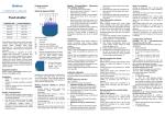
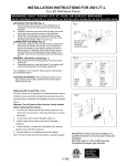
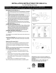
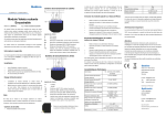
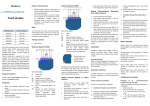
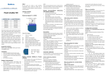
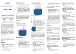
Qubino Electrical diagram 230VAC Module Inclusion (Adding to Z-Wave network) L N Flush dimmer bring module within maximum 1 meter (3 feet) of the main enable add/remove mode on main controller, Available configuration parameters (data type is 1 Byte DEC): auto-inclusion (30 minutes after connected to power supply) or default value 255 press service button S for more than 2 seconds or 255 - ALL ON active, ALL OFF active. press push button I1 three times within 3s (3 times change switch 0 - ALL ON is not active, ALL OFF is not active 1 - ALL ON is not active, ALL OFF active 2 - ALL ON active, ALL OFF is not active TS Module Exclusion/Reset (Removing from Z-Wave network) Type: Flush dimmer 1 NC (normaly close) input type state within 3 seconds). Ordering code: ZMNHDA2 0 NO (normaly open) input type Connect module to power supply, controller, L N default value 0 The INNOVATIVE and SMALLEST I1 I2 I3 Q Parameter no. 10 - Activate / deactivate functions ALL ON / ALL OFF Dimmer module responds to commands ALL ON / ALL OFF that may be sent by the main controller or by other controller belonging to the system. This Z-Wave module is used for dimming the light or to manage the Notes for the diagram: speed of a fan. The module can be controlled either through a Z-Wave N Neutral lead Connect module to power supply, Parameter no. 30 - Saving the state of the device after a power network or through the wall switch. L Live lead bring module within maximum 1 meter (3 feet) of the main failure Q Output for electrical device controller, Available configuration parameters (data type is 1 Byte DEC): I3 Input for switch/push button or sensor The module is designed to be mounted inside a “flush mounting box” and is hidden behind a traditional wall switch. Module measures power consumption of light or fan and supports I2 Input for switch/push button or sensor I1 Input for push button TS Terminal for digital temperature sensor (only for Flush connection of digital temperature sensor. Before the installation disconnect power supply. Connect the module according to electrical diagram. Locate the antenna far from metal elements (as far as possible). Do not shorten the antenna. I1 I2 I3 Q L N 1 - Dimmer module does not save the state after a power failure, it returns to "off" position If service button S is pressed more than 2 and less than 6 second Parameter no. 40 – Power reporting in Watts on power change module is excluded, but configuration parameters are not set to default Set value means percentage, set value from 0 - 100=0% - 100% values. Available configuration parameters (data type is 1 Byte DEC): default value 5 0 – Reporting Disabled 1 – 100 = 1% - 100% Reporting enabled. Power report is send Association enables Flush dimmer module to transfer commands inside (push) only when actual power in Watts in real time change for Z-Wave network directly (without main controller) to other Z-Wave more than set percentage comparing to previous actual power in Watts, step is 1%. NOTE: if power changed is less than 1W, the report is not send (pushed), Associated Groups: independent of percentage set. Group 1: multilevel (triggered at changes of state/value of the Flush dimmer) Parameter no. 42 – Power reporting in Watts by time interval Group 2: basic on/off (triggered at change of the input I2 state and Set value means time interval (0 – 65535) in seconds, when power reflecting its state) report is send. Group 3: basic on/off (triggered at change of the input I3 state and Available configuration parameters (data type is 2 Byte DEC): reflecting its state) default value 300 (power report in Watts is send each 300s) Group 4: default reporting group (reserved for the main controller) 0 – Reporting Disabled 1 – 65535 = 1 second – 65535 seconds. Reporting enabled. Power performed only by a qualified and licensed electrician. Notes for the diagram: Even when the module is turned off, voltage may be present on its N + 24VDC terminals. Any works on configuration changes related to L - 24VDC Q Output for electrical device I3 Input for switch/push button or sensor I2 Input for switch/push button or sensor I1 Input for push button Parameter no. 2 – Input 2 contact type Parameter no. 60 – Minimum dimming value TS Terminal for digital temperature sensor (only for Flush Available configuration parameters (data type is 1 Byte DEC): Available configuration parameters (data type is 1 Byte DEC): dimmer module compatible digital temperature sensor, default value 0 Default value 1 (Minimum dimming value is 1%) which must be ordered separately). 0 NO (normaly open) input type 1- 98 = 1% – 98%, step is 1%. Minimum dimming values is set by 1 NC (normaly close) input type connection mode or load must be always performed by disconnected power supply (disable the fuse). Note Do not connect the module to loads exceeding recommended values. Connect the module only in accordance to the below diagrams. Improper connections may be dangerous. Flush dimmer Configuration parameters report is send with time interval set by entered value. entered value. NOTE : The maximum level may not be lower than the minimum level! Package contains: to the last position saved before a power failure) modules. TS Module installation requires a great degree of skill and may be 0 - Dimmer module saves its state before power failure (it returns Association Danger of electrocution! and own ID is deleted. Electrical diagram 24VDC default value 0 press service button S for more than 6 seconds or By this function all parameters of the module are set to default values which must be ordered separately). Installation state within 3 seconds) dimmer module compatible digital temperature sensor, + enable add/remove mode on main controller, press push button I1 five times within 3s (5 times change switch Supported switches Module supports mono-stable switches (push button - I1). S Service button (used to add or remove module from the Z-Wave network). Parameter no. 3 – Input 3 contact type Available configuration parameters (data type is 1 Byte DEC): 1% min. dimming value is defined by Z-Wave multilevel device class. Parameter no. 61 – Maximum dimming value Light types which support dimming function: Available configuration parameters (data type is 1 Byte DEC): Default value 99 (Maximum dimming value is 99 %) The classical incandescent light. 2- 99 = 2% – 99%, step is 1%. Maximum dimming values is set by Halogen lamps operated by 230 V AC (High Voltage Halogen). entered value. Low voltage halogen lamps with electronic or conventional NOTE : The maximum level may not be lower than the minimum level! 99% max. dimming value is defined by Z-Wave multilevel device class. Parameter no. 65 – Dimming time (soft on/off) transformer. Dimmable fluorescent Light. Dimmable compact fluorescent light (CFL). Dimmable LED lights. Set value means time of moving the Dimmer between min. and max. dimming values by short press of push button I1 or controlled through UI. Important disclaimer Available configuration parameters (data type is 1 Byte DEC): Default value 100 (Dimming time between min. and max. dimming values is 1s) 1- 255 = 10mseconds – 2550mseconds (2,55s), step is Z-Wave wireless communication is inherently not always 100% reliable, and as such, this product should not be used in situations in which life and/or valuables are solely dependent on its function. 10mseconds Parameter no. 66 – Dimming time when key pressed Time of moving the Dimmer between min. and max dimming values by continues hold of push button I1. Default value 3 (Dimming time between min. and max. dimming values is 3s) Contact your local government for information regarding the collection systems available. If electrical appliances are disposed of in landfills or dumps, hazardous substances can leak into the groundwater and get 1- 255 = 1 second – 255 seconds into the food chain, damaging your health and well-being. When replacing old appliances with new once, the retailer is legally obligated Technical Specifications Power supply Do not dispose of electrical appliances as unsorted municipal waste, use separate collection facilities. Available configuration parameters (data type is 1 Byte DEC): Warning to take back your old appliance for disposal at least for free of charge. 110 - 230 VAC ±10% 50/60Hz, This user manual is subject to change and improvement without notice. 24-30VDC Rated load current of AC output 0,85A / 230VAC Rated load current of DC output 0,85A / 30VDC Output circuit power of AC output 200W (230VAC) (resistive load)* Output circuit power of DC output 21W (24VDC) (resistive load) Power measurement accuracy Frequency Range Digital temperature sensor range +/-2W 868.42MHz, Z-Wave -50 ~ 125°C (sensor must be ordered Distance 5250 Solkan -10 ~ 40°C Weight 41,8 x 36,8 x 15,4mm 25g Electricity consumption 0,7W For installation in boxes Ø ≥ 60mm or 2M Switching Slovenia up to 30 m indoors (depending on building materials) Dimensions (W x H x D) Goap d.o.o. Nova Gorica Ulica Klementa Juga 007 separately) Operation temperature Qubino MOSFET E-mail: [email protected] Tel: +386 5 335 95 00 Web: www.qubino.com Date: 24.04.2014 *max 100W mono-phase asynchronous fan motor can be Document: Qubino_Flush dimmer user connected to dimmer output manual_V3.0_eng