Transcript
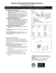
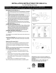
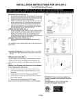
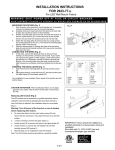
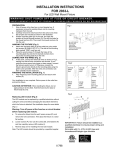
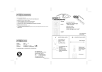
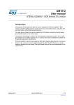
INSTALLATION INSTRUCTIONS FOR 2921-77-L
For LED Wall Mount Fixture
W A R N I N G ! S H U T P O W E R O F F AT F U S E O R C I R C U I T B R E A K E R .
AV E R T I S S E M E N T ! C O U P E R L E C O U R A N T A U N I V E A U D E S F U S I B L E S O U D O D I S J O N C T E U R .
MOUNTING THE FIXTURE (Fig. 1)
1.
2.
3.
Shut off power at the fuse box or circuit breaker box. If
necessary, remove the existing fixture and its mounting
hardware.
Carefully remove the new fixture from the carton and check
that all parts are included as shown in the illustration.
Attach the mounting plate (A) to the junction box using
junction box screw (B) (Size: 8-32*1/2’’L). The side of the
mounting plate marked “GND” must face out.
Fig.1F
CONNECTION THE WIRES (Fig. 2)
4.
Connect the electrical wires as shown in Fig.2, making sure
that all wire connectors are secured. If your outlet has a
ground wire (green or bare copper), connect the fixture's
ground wire to it. Otherwise, connect the fixture's ground
wire directly to the mounting plate using the green screw
provided. Tuck the wire connections neatly into the junction
box.
FINISHING THE INSTALLATION (Fig. 1)
5.
6.
Fig. 2
Align Fixture (E) onto mounting plate (A) and secure with
screws (D).
Place glass shade (L) inside the fixture (E), and secure with
screw (Q) steel washer (P) and plastic washer (O).
Your installation is now complete. Return power to the junction
box and test the fixture.
CAUTION /ATTENTION: When handling the fixture, do not
apply pressure to the LEDs. Hold the fixture by the base or
fixture body (E) only.
Replacing LED module (Fig. 1 & 3)
The LED module can be replaced by a qualified electrician without
cutting the wires and without damaging the decorative element to
Fig.3
which the fixture is attached. See installation steps for more details
(Fig 3.)
Warning: Turn off power at the fuse box circuit breaker
before replacing LED module.
a.
To remove the fixture from the wall: loosen screws (D), and
remove the wire connectors. Then place the fixture on a clear
flat surface.
b.
Loosen screw (Q) to remove the glass shade (L).
b. Loosen screws (G) to remove end caps (H) and glass
shade (K).
c.
Loosen screws (J), screws (M), wire fastener (N), and then
carefully remove the LED module (I).
d.
Reverse steps a-c for installing the new LED module.
Note: The LED module should be provided by a specified supplier.
II 785
IMPORTANT: Fixture should be installed by a
qualified electrician to ensure proper wiring and
installation.
Dimmable with C-L (CFL & LED) type and
Incandescent/Halogen type dimmers