1
Logiturn® III
Installation Manual
®
Logiturn III
Installation Manual
for
ECCO Full-Height Turnstiles
urnstiles
© Karl Gotschlich Maschinenbau GesmbH
LOGITURN3 Installationsanleitung ECCO.V3-6_en.docx.docx/25.01.2013
Logiturn® III
Installation Manual
Version Date
Comment
Rev.V1
Rev.V2
Rev.V3
Rev.V3.2
Rev.V3.5
Rev.V3.6
Rev.V3.6
AW first draft, based on rev. 5.2 Logiturn 2 rotate
Further developed and checked by Peter A.W.
A.W. May 5, 2012
A.W. Implementation of photos
A.W. HWBT removed.
Block diagram, current Terminal diagram, current A.W.
Completion, inserted CE document, current warnings and
errors, A.W.
6/2/2011
6/8/2011
4/14/2012
9/30/2012
11/18/2012
11/25/2012
12/23/2012
© Karl Gotschlich Maschinenbau GesmbH
Page 2 of 54
Logiturn® III
Installation Manual
Contents
1 Explanation of symbols....................................................................................................... 5
1.1 Warnings ................................................................................................................................................. 5
1.2 Information ............................................................................................................................................. 5
2 General information ........................................................................................................... 6
2.1 About this document ............................................................................................................................... 6
2.2 Operating safety ...................................................................................................................................... 6
2.3 General safety instructions ...................................................................................................................... 7
2.4 Reoccurring checks and maintenance ..................................................................................................... 7
3 Logiturn® ............................................................................................................................ 8
3.1 Logiturn expansion components are: ...................................................................................................... 8
4 Setup and Installation of an ECCO turnstile ................................................................. 10
4.1 Installation steps .................................................................................................................................... 10
4.2 Changing the locking direction in power-off mode .............................................................................. 17
4.3 Instructions for the roof installation ...................................................................................................... 19
5 Electrical installation instructions ................................................................................... 20
5.1 Power supply ......................................................................................................................................... 20
5.2 Protective grounding ............................................................................................................................. 20
5.3 Connecting cables ................................................................................................................................. 21
5.4 Connection of operating devices ........................................................................................................... 21
5.4.1 "Mini-GTC" software control panel .............................................................................................. 22
5.4.2 Hardware control panel .................................................................................................................. 23
6 Control functions .............................................................................................................. 25
6.1 Connecting a card reader, coin acceptor or other release mechanisms as well as different command
message devices .......................................................................................................................................... 25
6.1.1 Contact inputs: ............................................................................................................................... 25
6.1.1.1 Connection example release via peripheral device ............................................................. 26
6.1.1.2 Connecting a fire alarm system........................................................................................... 27
6.1.2 Logic outputs ................................................................................................................................. 27
6.1.2.1 Plug allocation for signal lights and lane signals: ............................................................... 27
6.1.2.2 Signal lights ........................................................................................................................ 28
6.1.2.3 Two direction-related signal lights with prompt symbols .................................................. 28
6.1.2.4 Connection of a release signal light with external power supply ....................................... 28
6.1.2.5 Feedback signal, counter, error, alarm ................................................................................ 30
6.2 Expansion board.................................................................................................................................... 32
6.3 Basic settings ........................................................................................................................................ 32
6.3.1 DIP switch settings ........................................................................................................................ 32
6.3.2 [DIP 1...3] Turnstile ID .................................................................................................................. 33
6.3.3 [DIP 4] Changing the locking direction in power-off mode .......................................................... 33
6.3.4 [DIP 5] Toggle configuration from 2Arm (180°) to 4Arm (90°) division ..................................... 33
6.3.5 [DIP 6] Direction of rotation.......................................................................................................... 33
6.3.6 [DIP 7] Test and initialization runs ................................................................................................ 34
6.3.7 [DIP 8] RM4 = Alarm .................................................................................................................... 34
6.4 Parameter .............................................................................................................................................. 35
6.4.1 Parameter menu for turnstile .......................................................................................................... 35
6.4.2 Parameter values and functions ..................................................................................................... 36
6.4.2.1 Anti Pass-Back Logic ......................................................................................................... 40
Anti Pass-Back Logic ......................................................................................................................... 40
6.4.3 Factory settings .............................................................................................................................. 41
6.5 Errors and warnings .............................................................................................................................. 43
6.5.1 LED error indicator: ....................................................................................................................... 43
© Karl Gotschlich Maschinenbau GesmbH
Page 3 of 54
Logiturn® III
Installation Manual
6.5.2 Error types ...................................................................................................................................... 44
6.5.3 Troubleshooting ............................................................................................................................. 45
6.5.3.1 To-do lists ........................................................................................................................... 45
6.5.3.2 Replacement parts ............................................................................................................... 46
6.5.4 Warnings ........................................................................................................................................ 47
7 Hardware controls ............................................................................................................ 48
7.1 Turnstile control unit............................................................................................................................. 48
7.1.1 Block schematic diagram ............................................................................................................... 48
7.1.2 Control board (layout for HW rev.4) ............................................................................................. 49
7.1.3 Connection terminals ..................................................................................................................... 50
7.2 Expansion board.................................................................................................................................... 52
7.3 Control panel ......................................................................................................................................... 52
8 General troubleshooting ................................................................................................... 53
8.1 Semiconductor outputs are not functioning: ......................................................................................... 53
8.2 Problems during turnstile startup .......................................................................................................... 53
8.3 Problems with communication ............................................................................................................. 53
8.3.1 RS-485 interface ............................................................................................................................ 53
8.3.2 Problems with the test runs ............................................................................................................ 53
9 CE Declaration of Conformity.................................................................................. 54
© Karl Gotschlich Maschinenbau GesmbH
Page 4 of 54
Logiturn® III
Installation Manual
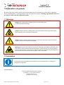
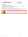
1 Explanation of symbols
Warning signs warn against actions and situations that may pose a danger to persons and/or equipment.
These are indicated by a warning triangle to the left of the text column. Warning signs must be observed
in order to retain warranty rights and claims.
1.1 Warnings
Danger: This symbol warns of danger that may cause bodily injury,
as well as equipment damage.
Danger: Danger caused by rotating parts. Disconnect the device from the power supply
when working in close proximity of these parts.
Danger: Danger caused by electrical energy. Do not touch these parts unless the power
supply to the device has been disconnected.
Warning: Electrostatically sensitive components. Discharge hands against grounded metal
parts before contact with the affected components. Control boards may not be removed
from the metal housing. The device must be connected to the protective grounding before
the protective cover of the control unit (yellow cover) is removed.
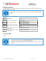
1.2 Information
This provides important additional information in cases in which there is no danger to
personnel or equipment.
The manufacturer
Karl Gotschlich Maschinenbau GesmbH
Feistlgasse 6, 1210 Vienna, Austria
0043/1/259 65 18 0*
Fax 0043/1/259 65 18 6
© Karl Gotschlich Maschinenbau GesmbH
Page 5 of 54
Logiturn® III
Installation Manual
2 General information
2.1 About this document
This is a combined manual for the product ECCO Logiturn.
This manual was designed mainly for IBN technicians and product users who are already familiar with the
products of the Logiturn family and their basic functions.
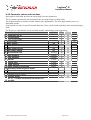
In addition to this manual, other installation instructions and operating instructions of the individual product
components are available as listed in the table below.
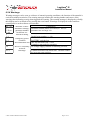
Title
Version
Note
Hardware control panel for turnstiles
and revolving/swing gates (for manual
operation)
Hardware control panel
User operating instructions
Logiturn Mini-GTC operating software
for turnstiles and revolving/swing gates
Logiturn expansion board
Power supply installation manual
Copying of the parameter and update of
firmware
Lane signals and signal lights
V3.3
Technical Description
V11.0
Designed for reception personnel,
cashiers, etc.
For configuration and servicing
purposes
Option
Connects to the power supply
For use with the HWBT (hardware
control panel)
Installation and par. manual
V2.1
V3.1
V1
V1.5
V6.4
2.2 Operating safety
The set-up should only be carried out by trained technicians. Assembly should only be
carried out by installers who are familiar with the equipment and have been trained
accordingly.
All electrical connections that are not within the low safety voltage range – primarily the
input leads for applying the supply voltage – must be carried out by a licensed electrician.
© Karl Gotschlich Maschinenbau GesmbH
Page 6 of 54
Logiturn® III
Installation Manual
2.3 General safety instructions
•
•
•
Operating personnel should be trained based on the “Hardware control panel
user operating instructions" during commissioning and then retrained on a
regular basis.
The turnstiles should only be operated according to their intended use.
For example: A turnstile is only intended for the passage of a person. Using it as a
child's toy or as a passage for bulky objects is not permitted.
If a malfunction occurs, the device must be immediately taken out of service by
switching off the power supply and by mechanically locking the locking drum.
Malfunctions are present, if the arms:
o do not stop at the home position,
o continue to rotate without authorization or being triggered by a person
o have uncontrolled movements
or, if
o the obstacle detection system (pressing of a trailing arm against a passing
person) is not activated, or only activated with unacceptable high force.
o visual mechanical damages on the turnstile do not allow risk-free use any
more.
Repairs must first be made before being put back into service.
Unintended restart prior to maintenance must be ensured.
•
Soiling due to iron-containing dust, abrasive dust or similar during the
construction phase can lead to surface damage (corrosion seeds).
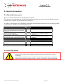
2.4 Reoccurring checks and maintenance
The turnstile is part of the "power operated doors" product group and must be checked for
safe functioning and serviced at least 1* per year according by an expert according to the
Work Equipment Regulation (AM-VO). Written records must be kept for the checks e.g.
plant test book.
© Karl Gotschlich Maschinenbau GesmbH
Page 7 of 54
Logiturn® III
Installation Manual
3 Logiturn®
is a registered trademark for a microprocessor control unit, which has been developed for Gotschlich
turnstiles, gates and motor-powered revolving/swing gates. This control unit has major expansions and addon modules available.
This control unit can be set by changing a wide range of parameters for different customer requirements and
product use. This enables Gotschlich turnstiles to be customized quickly to customer requirements, without
additional components and be flexibly integrated into the access control system.
Logiturn III
is a further development of the hardware and software and contains the following expansions:
-2 semiconductors for the direct connection of LED release signals
-2 semiconductors for the connection of LED lane signals with symbols
-2 further optical coupler inputs at the expansion board
- the overvoltage capability and the suitability for unstable grids (voltage and frequency fluctuations) have
been increased with respect to supply voltage.
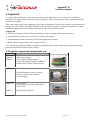
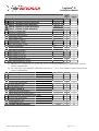
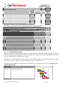
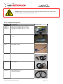
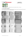
3.1 Logiturn expansion components are:
Item no.
2P404-N
2P405-N
Component
Expansion boards:
with 4 relay outputs
with 4 optical coupler outputs
(each with a battery charger and RS232
interface and 2 optical coupler inputs)
2P511A-N
Power-off lock mechanism
Illustration
Locks during power outage, locking
direction can be selected during
commissioning.
8P408S-N
Control panel
for operation, parameter setting and for
service work
8P407-N
Desk console (optional)
© Karl Gotschlich Maschinenbau GesmbH
Page 8 of 54
Logiturn® III
Installation Manual
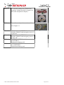
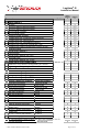
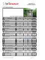
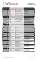
8P502-N
PC software package for operation and
parameter setting (includes a program CD,
data cable and protocol adapter)
2P811
Turnstile control panel connection cable
See Chapter 5.3.
8P416-N
8P406-N
3P321
3P330
UPS 2.1Ah for LOGITURN 3
Includes 2P404-N, and emergency power of
at least 4h
UPS 10Ah for LOGITURN 3
Includes 2P404-N, and emergency power of
at least 14h
BUFFER BATTERY 2.1Ah for
LOGITURN 3
Replacement battery pack
BUFFER BATTERY 10Ah
for LOGITURN 3
Replacement battery pack
© Karl Gotschlich Maschinenbau GesmbH
Page 9 of 54
Logiturn® III
Installation Manual
4 Setup and Installation of an ECCO turnstile
4.1 Installation steps
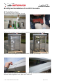
The following tools are required for work:
Supply of the wrapped turnstile, ready for function, tested and attached to a pallet.
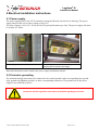
Step 1: Remove packaging foil; check the turnstile for transport damages
Step 2: Remove the gearbox cover plate using a 4mm hex wrench. The screws are alternately
loosened until the gearbox cover plate can be removed.
© Karl Gotschlich Maschinenbau GesmbH
Page 10 of 54
Logiturn® III
Installation Manual
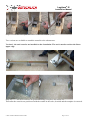
Step 3:
The rotor is loosened from the flange.
Step 4:
The rotor is lifted from the turnstile, the transport pins are removed from the pallet.
Step 5:
The turnstile should be secured using a forklift or other lifting device. The belts should be
tightened.
The turnstile must be secured against tipping over prior to performing any further assembly
steps!
© Karl Gotschlich Maschinenbau GesmbH
Page 11 of 54
Logiturn® III
Installation Manual
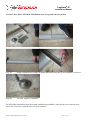
Step 6: Loosen the cover plate and unscrew the feet from the pallet.
Two versions are available to attach the turnstile to the substructure.
Version 1, the steel consoles are installed on the foundation. The steel consoles reach to the floors
upper edge.
Step 7A:
The steel consoles are positioned using a template and drilled out.
Thereafter the consoles are positioned with the washer in the scale, doweled and the template is removed.
© Karl Gotschlich Maschinenbau GesmbH
Page 12 of 54
Logiturn® III
Installation Manual
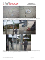
Version 2, base plate =FFOK=0. Installation onto an exposed concrete surface.
Step 7B:
Using a template, the borings are made and dowels are placed. The template is removed.
Step 8B:
The floor support is installed.
The following illustrations show the further installation possibilities, whereby the steel consoles were
placed acc. to version 1 and the floor set-up is complete.
© Karl Gotschlich Maschinenbau GesmbH
Page 13 of 54
Logiturn® III
Installation Manual
Step 8A:
After installing the consoles the floor structure is completed up to the upper edge of the
consoles and the floor support is installed on level ground using 2 washers.
Step 9: The turnstile is lifted from the pallet as a complete portal and positioned on the prepared set-up
location. The cable leads are guided through the base prior to moving.
© Karl Gotschlich Maschinenbau GesmbH
Page 14 of 54
Logiturn® III
Installation Manual
Step 10: The portal is placed in both axis in the scale and also leveled using washers. The base pedestals are
also bolted.
Step 11: The connection to the central ground is provided. Thereafter place the supply voltage on the
terminals.
The connection to the central ground as well as to the voltage supply must be made by an
authorized licensed electrician and the bleeder resistor is checked.
Step 12: Bolt the covers of the support pedestals and lubricate the bearing pins.
© Karl Gotschlich Maschinenbau GesmbH
Page 15 of 54
Logiturn® III
Installation Manual
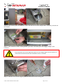
Danger: Danger caused by rotating parts. Disconnect the device from the power supply
when working in close proximity of these parts. In particular, it must be ensured that a
second person, installer assistant, does not move the arms of the turnstile and thereby
power the locking unit while in proximity of the moving parts.
Step 13: Place the rotating drum on the bearing pins and rotate in a manner that the index borings
(ARROW) are flush with a row of the arms. On drives with the option "Power-off lock mechanism" check
the locking direction and if required adjust as described in Chapter 4.2.
Step 14: Bolt the rotating drum flange to the drive shaft, check if the rubber elements of the gear seat plate
have sufficient play upwards and downwards. The rotating drum must be able to be lifted together with the
gear about 5mm. The rotating drum must be manually rotatable when the turnstile is in a currentless state.
© Karl Gotschlich Maschinenbau GesmbH
Page 16 of 54
Logiturn® III
Installation Manual
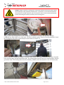
Step 15: Position the support legs of the guide rails, under pressure, against the finished floor and secure
using counter nuts. Remove the yellow cover on the Logiturn® control unit.
Step 16: Perform a function check using the control panel. The parameter values can be adjusted to the
conditions during "Parameter" mode, also refer to the "Hardware control panel" operating instructions.
Check the locking direction while in power-off mode and change if required according to the description in
the following Chapter 4.2. Set the entrance and exit direction according to the requirements at the
installation site using DIP switch 6, refer to Chapter 6.2.5. Connect the card reader or other release devices.
Subsequently, install the gearbox cover plate.
4.2 Changing the locking direction in power-off mode
Loosen the 7 pcs. of ISK counter-sunk screws, lift the ratch wheel, turn and bolt down
again.
Pay attention to proper positioning of the index pin.
Locking
direction
© Karl Gotschlich Maschinenbau GesmbH
DIP switch 4 = 0
Page 17 of 54
Logiturn® III
Installation Manual
Locking
direction
DIP switch 4 = 1
Switch over DIP switch 4 during changes of the locking direction.
24V~
0V~
GND
RX/TXRX/TX+
5
4
3
2
1
0V~ out
24V~ out
AMP1/NO
AMP1/COM
AMP1/NC
AMP2/NO
AMP2/COM
AMP2/NC
8
7
6
5
4
3
2
1
1
2
3
4
5
6
7
8
9
10
11
12
X01A
X01B
MOT+
MO
O +
MO
MOTOTBR+
B
+
BRR-R
+24V
4V
V
GND
G
ND
N
D
DG
DG
RII
R
+24V
+
24
4V
V
ES1
ES1
S1
ES2
E
S2
2
AMP1
AMP2
X02
X03
12
11
10
9
8
7
6
5
4
3
2
1
EMQ+
Q+
EMQQALARM
RM
M
GND
G
ND
N
D
DIP SWITCH
X
X10
X08
24V~
0V~
GND
RX/TXRX/TX+
X19
X1
1
S2
S2
X18
X1
1
S1
X17
7
L2
L
2
X16
X04
X04
4
3
2
1
X07
L
L1
X05
X
0
X06
ON
OFF
1 2 3 45 67 8
S
Sen4
Sen2
en Sen1
n1 Sen3
1
1
1
1
X13
OUT A
GND
GND
+24V
+24V
COM BC
B
C
COM EFG
E
F
G
5
4
3
2
1
Si
6,3AT
24V
Senx
Sig
g 1/2
GND
Sen
© Karl Gotschlich Maschinenbau GesmbH
Page 18 of 54
Logiturn® III
Installation Manual
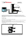
4.3 Instructions for the roof installation
1. Step: Lift the basic roof construction
onto the turnstile and bolt down in the
indicated position (detail of bolting).
Roof bolting
2. Step: Bolt down the spring clips and
panel adapter to the roof underside onto
the mounting rail using threaded clips and
M5 socket head screws (detail of
fastening).
Panel adaptor (side) Spring clip (front)
3. Step: Slide the lateral roof cladding
profile over the springs of the cladding
adapter. Watch for latching of the profile
to the upper and lower roof edge (detail
of latching).
Latching
4. Step: Clip the face cladding profile
below into the spring clip, then on
upwards, press over roof edge. Watch for
latching of the profile to the upper and
lower roof edge (detail of installation
steps).
Mounting below Mounting top
5. Step: Place cladding corners, drill holes
on top and below for blind rivets in the
cladding profile, place blind rivets (detail
of installation steps).
Place corner
6. Step: Bolt the bottom view cladding
panels to the cladding adapter (insert M5
threaded clip) using M5 counter-sunk
screws (detail of bolting).
Bolting
© Karl Gotschlich Maschinenbau GesmbH
Page 19 of 54
Logiturn® III
Installation Manual
5 Electrical installation instructions
5.1 Power supply
The power supply unit for the ECCO turnstile is integrated directly into the device housing. The power
supply unit provides a low safety voltage of 24 VAC.
The power supply is 230 VAC, 50 Hz and 100 W peak performances per lane. The power supply line must
be at least 3x1.5mm².
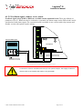
Power supply on turnstile with Front Box
Power supply on turnstile where the power
supply pack is located in the bridge
Detailed information can be found in the power supply installation manual.
5.2 Protective grounding
The turnstile housing must always be connected to the central ground with a corresponding base ground
strip, ground rod (lightning arrester) or other corresponding connection. The ground wire in the power
supply is not sufficient by itself!
Respective national regulations must always be followed regarding this measure.
© Karl Gotschlich Maschinenbau GesmbH
Page 20 of 54
Logiturn® III
Installation Manual
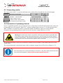
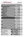
5.3 Connecting cables
The "gray system cable" is a special cable that can be ordered from Gotschlich in the desired lengths.
Item no. Electrical connection
2P811
Turnstile – control panel
Contact inputs release
Counter output, alarm output
Fire alarm system contact input
Type
Gray system cable
0.5mm² flex wire
0.5mm² flex wire
0.5mm² flex wire
Max.
length
30m
30m
30m
30m
5.4 Connection of operating devices
Up to 2 Logiturn® turnstiles can be connected to one control panel via the RS-485 data bus line or they can
be controlled via a PC using the "Mini-GTC" software package and a converter. To do this, the data lines
RXT+ and RXT- of all devices must be connected together. In addition, please also ensure that the
potentials of the grounding points of all devices do not exceed a voltage difference of ±50V.
Warning: Electrostatically sensitive components. Discharge hands against grounded metal
parts before contact with the affected components. Control boards may not be removed
from the metal housing. The device must be connected to the protective grounding before
the protective cover of the control unit (yellow cover) is removed.
The shield connections of the devices should be connected to one another via the shield drain wire of the
system cable.
The connected turnstile control units must each be assigned a unique device ID (refer to Chapter 6.2.2).
The control panel can only be powered by the turnstile 1. The power supply of both turnstiles
may not be linked together. SHORT CIRCUIT OF BOTH POWER SUPPLIES!
© Karl Gotschlich Maschinenbau GesmbH
Page 21 of 54
Logiturn® III
Installation Manual
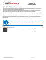
5.4.1 "Mini-GTC" software control panel
The software control panel is a "Mini-GTC" software package programmed on an ACCESS user interface
and can be installed on a PC or laptop using Windows XP.
The PC is connected via an interface converter to the turnstile control unit. Connection is provided via a
RS-485 interface. Two converters with a RS-232 (V24) or with USB inputs are available.
The RS-232 or the USB connection cable between the PC and the converter should not be longer than 5 m.
The other connection from the converter to the turnstile control unit is made via the RS-485 data line
(2P811) and may be up to 30 m long.
The RS-232(V24) converter requires its own power supply of 24VDC. The USB converter is powered on
the USB side.
A detailed manual is available for the installation and commissioning. "Logiturn II Mini-GTC
operating software for turnstiles and revolving/swing gates V2.1"
Software package: "Mini-GTC"
Item no. Component
8P501
With interface converter for RS-232 and 1.5 m data cable SUB-D9
8P502
With interface converter for USB and 1 m USB connection cable
© Karl Gotschlich Maschinenbau GesmbH
Page 22 of 54
Logiturn® III
Installation Manual
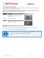
5.4.2 Hardware control panel
The control panel is used to operate the turnstile and to display various feedback signals on the two-part
display and also on the function keys via LEDs.
Parameters can be changed using the control panel. Extensive support for commissioning, service
purposes and maintenance is provided in the service menu.
Item no.
8P408S-N
Component
Control panel
for operation, parameter setting and for
service work
8P407-N
Desk console (optional)
2P811
Gray system cable for the connection of the
turnstile - control panel
Illustration
The control panel is also powered by the 24V~ low DC voltage generated by the power supply unit.
The connection cable must be shielded following EMC guidelines.
The detailed operating instructions "Hardware control panel for turnstiles" are available for
information on the installation and commissioning of the HWCP.
A separate "User manual" is available for the operating personnel to provide information for
operating.
© Karl Gotschlich Maschinenbau GesmbH
Page 23 of 54
Logiturn® III
Installation Manual
Simple configuration example: one turnstile with a control panel
The 2 ends of the RS485 interface line RXTX and RXTX+ are provided with a load
resistor of 120 Ohm directly at the terminal points.
© Karl Gotschlich Maschinenbau GesmbH
Page 24 of 54
Logiturn® III
Installation Manual
6 Control functions
6.1 Connecting a card reader, coin acceptor or other release
mechanisms as well as different command message devices
Logiturn® controls provide a multitude of connection possibilities for card readers, signal lights, lane
signals or other periphery devices. All sorts of feedback signals, interfaces and ready indicators for building
and safety equipment as well as fire alarm systems,
systems, for instance, are also available. The following inputs
and outputs are available:
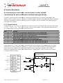
6.1.1 Contact inputs:
Contact inputs B, C, E, F and G are potential-free
potential free inputs activated with voltage levels typically in the range
of +12V…+24V or -12V…-24V
24V to set or revoke a release to the turnstile. The two contact inputs K and L
are available at the expansion board for special functions.
Entry
B
C
E
F
G
K
L
Function
Set release for entry direction, detailed function set with parameter 20
Same as B, but for exit direction, detailed function set with parameter 21
Same as B, detailed function set with parameter 22
Same as B, but for exit direction. Detailed function set with parameter 23
Revoke releases, set detail function with parameter 24.
SPECIAL FUNCTIONS AVAILABLE
AVAIL
ON THE EXPANSION BOARD
Alarm setting, preferred direction lane signal, toggle configuration par. 50
Alarm setting, preferred direction lane signal, toggle configuration par. 51
Contact inputs B, C, E and F are usually activated by the release signals of the peripheral devices. If the
peripheral device has potential-free
free outputs (e.g., relay or optical coupler outputs), the ground potential
must be connected with the associated COM terminal of the contact inputs and the +24V voltage is
activated by potential-free
free contacts of peripheral devices. Inputs B and C and E, F and G have separate
common terminals available.
Contact inputs for K and L at the
expansion board
© Karl Gotschlich Maschinenbau GesmbH
Page 25 of 54
Logiturn® III
Installation Manual
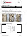
6.1.1.1 Connection example release via peripheral device
Fig. 1- Peripheral device with potential-free contacts
Kartenleser/Muenzpruefer=card reader / coin validator, Zusatzplatine = expansion board, Spannungsversorgung = voltage supply,
Freigabesignal = release signal, Scheusensteuerung- gate control
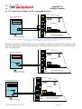
Should no potential-free outputs (such as with a semiconductor switch) be available, then, depending on the
type of the output stage, the COM terminal must be connected with the GND (Fig.22) or operating voltage
(Fig. 23) of the reader.
Fig. 2 - Peripheral device with PNP output
Fig. 3 - Peripheral device with NPN output
© Karl Gotschlich Maschinenbau GesmbH
Page 26 of 54
Logiturn® III
Installation Manual
The COM_BC and COM_EFG lines make it possible to connect two groups of independently powered
peripherals to the turnstile control unit.
Connections +24V are available exclusively for the optical coupler. The supply of external
devices such as card reader and similar is not permitted!
6.1.1.2 Connecting a fire alarm system
Four signal inputs (B, C, E and F) as well as K and L are available on the expansion board for connecting a
security system (fire alarm system, escape route terminal, emergency escape button, etc.) via parameter
inputs. This can be triggered by both a closer as well as a break contact.
6.1.2 Logic outputs
Available on the basic control unit are:
2 relay outputs "AMP1" and AMP2" for feedback, or signal light control.
2 transistor outputs, terminal A for passage counter pulse and terminal "Alarm" for alarm and warning
messages are available.
2 *3semiconductor outputs for the control of the LED release signals.
2 *3semiconductor outputs for the control of the LED lane signals.
A data interface RS-485 for connecting to the building control system.
Additional outputs are available on the expansion board, refer to Chapter 6.1.3.1.
A detailed manual "Installation Manual for signal lights and lane signals" is available. The
following chapter is a summary and is reduced to the special design of the ECCO turnstile.
6.1.2.1 Plug allocation for signal lights and lane signals:
Slot
Function
L1
"SIGNAL LIGHT" release
signal
"SIGNAL LIGHT" release
signal
Lane signal
Lane signal
L2
S1
S2
© Karl Gotschlich Maschinenbau GesmbH
Direction assignment
DIP 6=0
Entry direction
Direction assignment
DIP 6=1
Exit direction
Exit direction
Entry direction
Entry direction
Exit direction
Exit direction
Entry direction
Page 27 of 54
Logiturn® III
Installation Manual
6.1.2.2 Signal lights
SIGNAL LIGHTS with symbols
Article no.:
21764-N
21764-NA
Type
L411104- V2
L411104- V2
Description
Flat installation
Flat installation
Variant
Installation in new device
Retrofit installation
6.1.2.3 Two direction-related
related signal lights with prompt symbols
Appropriate parameter no. 48 value for this = 51
This example shows an ECCO turnstile with signal lights and card readers installed on the front door of
each entrance side. One of the two green arrows is used to display the turnstile release.
The other arrow symbol is set up mechanically so that it refers
refers to a card reader, coin deposit, button press or
similar action. The arrow symbol is used as a prompt symbol. The use of this device is required to trigger a
release of the turnstile. The prompt symbol flashes every 0.5s.
6.1.2.4 Connection of a release signal
signal light with external power supply
Two relay outputs (AMP1/AMP2) are available for signal lights with higher output, or signal lights that are
not compatible with standard LED signal lights.
Relay outputs block diagram
© Karl Gotschlich Maschinenbau GesmbH
Ampel
Ampel-Relais
= light signal relay
Page 28 of 54
Logiturn® III
Installation Manual
Example 1 shows a wiring plan for one red/green signal light per traffic direction.
Circuit diagram, example 1
Ausgang= exit, Eingang=entry, Richtung = direction
For this wiring example, parameter 28 = AMP1 should be set to value 60 and parameter 29 = AMP2 should
be set to value 70.
Superordinate malfunction message
The signal light relays of the Logiturn control are alternately activated in 1 second cycles, if a malfunction
(fault condition) occurs on the turnstile.
Terminals with 24VAC, 500mA max load are available at the turnstile control for the signal lights power
supply.
Signals with higher output and voltage must be powered externally. The maximum switching capacity of
relay AMP1 and AMP2 is 50VAC, 5Aeff.
© Karl Gotschlich Maschinenbau GesmbH
Page 29 of 54
Logiturn® III
Installation Manual
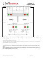
6.1.2.5 Feedback signal, counter, error, alarm
Feedback signal relays (RM1 to RM4) are available on the expansion board. These are defined via
parameters 30 to 33. RM4 can also be switched to a potential-free alarm output via the DIP switch 8 and is
synchronized with alarm output. The expansion board is available in one version with relay contacts and
another version with optical coupler outputs.
Fig. Peripheral device with potential-free feedback input
Connections +24V are available exclusively for the optical coupler. The supply of external
devices such as card reader and similar is not permitted!
© Karl Gotschlich Maschinenbau GesmbH
Page 30 of 54
Logiturn® III
Installation Manual
24 ~
0~
Sch
RXTXRXTX+
0~
24 ~
NO1
Kartenleser / Münzprüfer
CO1
NC1
NO2
CO2
NC2
OUT A
Zusatzplatine
GND
±5 … 50V
GND
+24V
+24V
B
NO3
CO3
NC3
NO4
CO4
NC4
GND
24V
NO1
CO1
NC1
NO2
CO2
NC2
COM BC
C
COM EFG
E
F
Logiturn Schleusensteuerung
G
Spannungsversorgung
X03
Rückmeldung
Fig. Peripheral device with voltage input for feedback
By setting the right parameters, the AMP1 and AMP2 signal light relays can also be used for
feedback signals to card readers. The conditions for switching the relays on and off can be defined for
different characteristics via parameters 28 and 29 (e.g., enabling/disabling releases, starting/stopping
starting/stoppi traffic,
pulse signals, etc.).
Transistor outputs
The Logiturn basic control unit provides 2 transistor outputs.
Out "A" provides counter pulses and is used to control the external counter or to provide feedback signals.
Out A can be set via parameter 25 and 26.
Out "Alarm" provides an operation ready message, different warning and alarm messages for the
connection to the building control systems or to control electro-acoustic
electro acoustic signal emitters. Out alarm can be
set via parameter 27.
The output voltage is 24VDC. The output has a max. load of 250mA.
Transistor outputs block diagr. Zählerausg
hlerausg.= counter output, Alarmausg.=
= alarm output
© Karl Gotschlich Maschinenbau GesmbH
Page 31 of 54
Logiturn® III
Installation Manual
6.2 Expansion board
A detailed description of the expansion board’s functions is available in a separate document: "Installation
instructions for the expansion board".
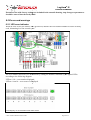
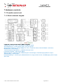
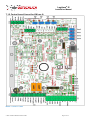
6.3 Basic settings
Basic settings are made directly on the control unit board via an 8-digit DIP switch.
6.3.1 DIP switch settings
24V~
0V~
GND
RX/TXRX/TX+
5
4
3
2
1
0V~ out
24V~ out
AMP1/NO
AMP1/COM
AMP1/NC
AMP2/NO
AMP2/COM
AMP2/NC
8
7
6
5
4
3
2
1
1
2
3
4
5
6
7
8
9
10
11
12
X01A
X01B
MOT+
MO
O +
MO
MOTOTBR+
B
+
BRR-R
+24V
4V
V
GND
G
ND
N
D
DG
DG
RII
R
+24V
+
24
4V
V
ES1
ES1
S1
ES2
E
S2
2
AMP1
AMP2
X02
X03
12
11
10
9
8
7
6
5
4
3
2
1
EMQ+
Q+
EMQQALARM
RM
M
GND
G
ND
N
D
DIP SWITCH
X
X10
X08
24V~
0V~
GND
RX/TXRX/TX+
X19
X1
1
S2
S2
X18
X1
1
S1
X17
7
L2
L
2
X16
X04
X04
4
3
2
1
X07
L
L1
X05
X
0
X06
ON
OFF
1 2 345 67 8
S
Sen4
Sen2
en Sen1
n1 Sen3
1
1
1
1
X13
OUT A
GND
GND
+24V
+24V
COM BC
B
C
COM EFG
E
F
G
5
4
3
2
1
Si
6,3AT
24V
Senx
Sig
g 1/2
GND
Sen
®
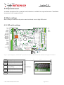
Fig. 1– Layout diagram, LOGITURN III printed circuit board with marked DIP switches and plug connections
DIP
1
2
3
4
5
6
7
8
Description
ID 1 (value: 1)
ID 2 (value: 2)
ID 3 (value: 4)
Locking direction during
power failure
Toggle configuration
Reverse direction of rotation
Initialization run active
RM4 = alarm
© Karl Gotschlich Maschinenbau GesmbH
Basic setting Illustration DIP switch
0
0
0
0/1 depends on
mechanics
0
0
1
0
Page 32 of 54
Logiturn® III
Installation Manual
6.3.2 [DIP 1...3] Turnstile ID
The ID value must be set for any Logiturn turnstile that is connected with the control panel via a RS-485
data line or the software control panel Mini GTC. This ID no. is then entered in CP parameter 60.
As per BCD coding, the number is defined using the first three DIP switches:
ID no.
BCD
0
1
2
3
4
5
6
7
DIP1
I
0
1
0
1
0
1
0
1
DIP2
II
0
0
1
1
0
0
1
1
DIP3
IV
0
0
0
0
1
1
1
1
Setting: ID1
Value 0 corresponds with switch setting OFF, value 1 with the setting ON
If this is set incorrectly, no communication with the turnstile control unit over the RS-485
interface is possible! The same IDs may not be used more than once within a
communication branch.
6.3.3 [DIP 4] Changing the locking direction in power-off mode
Here, the direction of rotation is set during the initialization run (switching on the operating voltage). It
must be adjusted depending on the installation position of the ratchet wheel properly, see Chapter 4.2.
6.3.4 [DIP 5] Toggle configuration from 2Arm (180°) to 4Arm (90°) division
On turnstiles with 2 barrier arms it is possible to switch over to operating mode with 4 barrier arms by
toggling the configuration.
Using switch setting ON, a 2 arm turnstile is converted to a 4 arm turnstile.
The turnstile performs an initialization run after any configuration change.
Practical use of this setting: It is possible to install a drive as spare part for a 2 arm turnstile or for a 4 arm
turnstile.
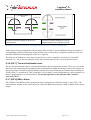
6.3.5 [DIP 6] Direction of rotation
Many turnstile parameters apply to a predefined entry or exit direction. This direction assignment can be
made using DIP switch 6 according to the following diagram. The definition of the entry and exit direction
is usually determined with the entry into or exit from an access-protected area.
When changing the direction of rotation, it must be noted that the contact inputs and all
feedback signals, lane signals and signal lights always refer to the actual entry or exit
direction and thus must be appropriately controlled.
This means that the right entry and exit direction for the location must be determined and
DIP switch no. 6 set accordingly.
© Karl Gotschlich Maschinenbau GesmbH
Page 33 of 54
Logiturn® III
Installation Manual
Drehsinn „On“
Eingang
Zutrittsgeschützter
Bereich
Ausgang
Ausgang
Drehsinn „0ff“
Eingang
Direction of rotation settings for access to a
protected area
Direction of rotation settings for a mirrorimage arrangement of a second turnstile
Drehsinn = direction of rotation, Zutrittsgeschützter Bereich = access protected area
With a mirror-image arrangement of the turnstiles (back to back or arm mechanisms facing one another) a
corresponding symmetrical behavior of the turnstiles can be achieved by setting the parameters of the two
turnstiles identically and setting DIP switch no. 6 opposite.
The direction definitions for entry and exit must be set, even if a turnstile is used only for one traffic
direction, e.g., one of the two turnstiles for the entry and the other for the exit of the protected area.
6.3.6 [DIP 7] Test and initialization runs
The test and initialization runs are executed immediately after activating the turnstile. They serve to test the
function of all components and synchronize the incrementally working measuring system to the position of
the turning arms. It should be ensured that the turnstile does not perform any movements after switching on,
if DIP switch 7 is switched off. This is desirable if, for example, a new configuration or a new parameter set
must be programmed in or tests performed. For normal operation of the turnstile, DIP 7 must be
activated ("ON").
6.3.7 [DIP 8] RM4 = Alarm
The feedback relay RM4 (on the expansion board) is synchronized with alarm output 1 when "ON." The
semiconductor outputs on the control board as well as the RM4 relay output are both available for the alarm
output.
© Karl Gotschlich Maschinenbau GesmbH
Page 34 of 54
Logiturn® III
Installation Manual
6.4 Parameter
6.4.1 Parameter menu for turnstile
The Logiturn turnstile control unit and the control panel can be adapted to many device configurations,
operating modes and operating conditions using parameters.
Parameters are saved to EEPROM (non-volatile storage).
Parameters can either be set from the hardware control panel or from a PC via the "Mini-GTC" program
(software control panel). Access to the parameter menu is protected via a code number.
The turnstiles are provided with parameter settings for average usage. It is the responsibility
of the project lead or technician, who is performing commissioning, to adjust these values
according to use to provide ideal comfort and highest protection against physical injuries.
© Karl Gotschlich Maschinenbau GesmbH
Page 35 of 54
Logiturn® III
Installation Manual
6.4.2 Parameter values and functions
Input options: Min/Max specifies the input range for some parameters.
The Z column represents the tens digit and E the ones digit of the two-digit value.
The default function is usually selected with the tens digit number. The ones digit enables you to set
individual options.
Some options are only for specific default functions. These can be listed separately in the tens digit using a
dash.
The X entry is a placeholder for all available number combinations in this parameter.
Parameter
Unit
Min
Max Value
0 Parameter set ID
0
255
1 Configuration
0
99
3-Arm, 4-Arm turnstile
2-Arm turnstile
2 Max. speed 1
3 Max. speed 2
4 Max. motor speed
5 Min. motor speed
6 Acceleration time
7 Start distance
8 Stop distance
9 Interval
10 Repeat time
11 Rated current
12 Home position correction
13 Operating mode magnetic brake
rps
rps
rps
rps
1/100 s
Pulses
Pulses
1/10 s
1/10 s
1/10 A
Pulses
0
0
99
99
6
13
6
17
12
25
2
10
40
99
1
20
10
99
2
20
20
50
0
30
25
70
4
0
1
2
99
Maximal mode
Minimal mode
Temperature sensor control
14 Division factor
Par 15....19 have no function for the ECCO
15 turnstile
© Karl Gotschlich Maschinenbau GesmbH
Page 36 of 54
12
22
Logiturn® III
Installation Manual
Parameter
20 Input B, release in entry direction
21 Input C, release in exit direction
22 Input E, release in entry direction
23 Input F, release in exit direction
Emergency release (ER)
Permanent release (PR)
Toggle permanent release
Single release (SR)
Single release+1 (SR+1)
SR with PR after 1.5 sec.
SR+1 with PR after 1.5 sec.
Release confirmation
Unit
Basic
function
Option
Z
E
0
1
1
2
3
4
5
6
x
x
4
x
x
x
x
0
9
2/3/4/5
2/3/4/5
2/3/4/5
9
9
x
1
2
3
0
1
See par. 23
See par. 23
See par. 23
1)
1)
2)
Alarm state (2-arm/180°)
Single release for 7 sec.
Single release for 12 sec.
Single release for 30 sec.
Alarm state activated by closer
Alarm state activated by opener
1) Option EF+1 (values 30, 31, 32, 33, 50, 51, 52, 53) is not permissible in combination with the
release confirmation.
2) No "time out" is permitted for individual releases of 7, 12, or 30 seconds in conjunction with the
release confirmation.
24 Input G, stop
Cancels last single release
Cancels all single releases and discontinues PR
Permanent releases are discontinued while there is a signal
For entry and exit direction
For entry direction only
For exit direction only
1
2
3
x
x
x
x
x
x
0
1
2
1
2
3
x
x
x
10
x
x
x
0
1
2
99
25 Counter output A
Pulse at end of turning motion
Pulse at beginning of turning motion
Continuous signal during entire turning motion
For entry and exit direction
For entry direction only
For exit direction only
26 Counter signal duration
© Karl Gotschlich Maschinenbau GesmbH
1/100 s
Page 37 of 54
Logiturn® III
Installation Manual
Parameter
27 Alarm output 1
Unit
No alarm
An error or warning signal is present
No error or warning signal is present
An error signal is present
No error signal present
Emergency power operation
Turnstile climb-over, movement sensor triggered
Turnstile climb-over, with IR sensor
Turnstile climb-over, with additional sensors
Turnstile home position not reached after 1min.
Turnstile home position reached prior to expiry of 1min
Continuous signal
Interval signal ("flashing")
5-second pulse
Interval signal ("flashing") for 5 sec.
10-second pulse
Interval signal ("flashing") for 10 sec.
28 Signal light relay output AMP1
Function / Switch-on condition
During entry movement
Start of entry movement
During exit movement
Start of exit movement
After entry movement
After exit movement
Inhibit on: Start entry movement
Inhibit on: End entry movement
Inhibit off: Start exit movement
Inhibit off: End exit movement
Release entry
Rel. ent. + release authorization
Release exit
Rel. exit + release authorization
Error or warning signal
Z
E
0
1
2
3
4
5
6
7
8
9
9
x
x
x
x
x
x
0
0..5
0..5
0..5
0..5
0..5
1..5
1..5
1..5
0
1
0
1
2
3
4
5
8
1
8
1
0
0
1
1
2
3
4
4
5
5
0
x
0
x
x
x
0
1
0
1
6
6
7
7
8
0
1
0
1
0
9
0
See par. 33
Feedback in exit direction during passing incl. sensor*
30 Feedback relay output RM1
31 Feedback relay output RM2
32 Feedback relay output RM3
33 Feedback relay output RM4
Option
See par. 33
Feedback in entry direction during passing incl. sensor*
29 Signal light relay output AMP2
Basic
function
See par. 33
See par. 33
See par. 33
Switch-off condition
Movement ended
Pulse ended
Movement ended
Pulse ended
Timing
Timing
Release
Release
Release
Release
End movement or
release
As above
As above
As above
No signal
3)
3) The parameter value 80 does not apply for parameter 28+29
Auto-stop activated
© Karl Gotschlich Maschinenbau GesmbH
Auto-stop reset
Page 38 of 54
Logiturn® III
Installation Manual
Parameter
33 Feedback relay output RM4 (Continuation)
Function / Switch-on condition
Pulse with 0.1…0.2 sec.
Pulse with 0.2…0.3 sec.
Pulse with 0.3…0.4 sec.
Pulse with 0.4…0.5 sec.
Pulse with 0.5…0.6 sec.
Pulse with 0.6…0.7 sec.
Pulse with 0.7…0.8 sec.
Pulse with 0.8…0.9 sec.
Pulse with 0.9…1.0 sec.
Unit
Basic
function
Option
Z
E
Switch-off condition
34 IR autostart
Direction:
No autostart
Autostart with release
Autostart if no autostop
35 IR start criteria
Direction:
IR sensors are not evaluated
K1: Triggers only, if person is in entry area
K2: Triggers only, if no person is in exit area
Apply K1 and K2
36 Closing criteria par. has no function for the ECCO turnst. Direction:
37 Alarm output 2 (output EM)
Place:
Not available for the ECCO turnstiles
38 Braking profile
Place:
Gradient of the target brake ramp in increments of 6……14
Steps
0/1/2/3
1
0/1/2/3
2
0/1/2/3
3
0/1/2/3
4
0/1/2/3
5
0/1/2/3
6
0/1/2/3
7
0/1/2/3
8
0/1/2/3
9
Entry Exit
0
0
1
1
2
2
Entry Exit
0
0
1
1
2
2
3
3
Entry Exit
Tens
Ones
0
0
Tens
Ones
1
1
39 Battery operation
End normal mode immediately
Normal mode for fixed time
Fixed time operation, exit = PR
Fixed time operation, entry = PR
Fixed time operation, EN+EX = PR
Alarm state
No time limit
Factor per 5 minutes
40 par. 40….47 have no function for the ECCO turnstiles
0
1
2
3
4
5
1/2/3/4
1/2/3/4
x
x
x
x
x
0
0
1-9
Z
0
3
4
5
6
7
X
X
E
0
X
X
X
X
X
1
2
48 Signal light model
Display
assignment
Slots L1 and L2 deactivated
2 direction-related signal lights
2 direction-related signal lights
With prompt symbol
With prompt symbol
2 direction-related signal lights
Release display with stop signal
Stop signal only for alarm signal
© Karl Gotschlich Maschinenbau GesmbH
normal
inverted
normal
inverted
Signal type
V1,V2
V2
V2
V2
V2
V1
V1,V2
V1,V2
Page 39 of 54
Logiturn® III
Installation Manual
49 Lane signal model
Basic
function
Option
Z
0
1
2
X
X
X
X
E
0
X
X
0
1
2
3
Basic
function
Option
Z
E
7
7
9
9
0
1
0
1
7
7
9
9
0
1
0
1
Display
assignmen
t
Signal type
S1 and S2 lane signal slots deactivated
V2
V2
Direction assignment of arrow symbol
normal
V2
Direction assignment of arrow symbol
inverted
V2
Basic setting of lane blocked in both directions
V2
Basic setting of preferred direction in entrance direction
V2
Basic setting of preferred direction in exit direction
V2
Basic setting of lane coordinated in both directions
Signal type V1 has a red and green lighted surface
Signal type V2 has a green arrow symbol and a red X as a blocked symbol
Parameter for the expansion board
Parameter
50 Input K, special function
Lane signal preferred direction in entrance direction
Lane signal preferred direction in exit direction
Unit
Alarm setting activated by closing contact
Alarm setting activated by opening contact
51 Input L, special function
Lane signal preferred direction in entrance direction
Lane signal preferred direction in exit direction
Alarm setting activated by closing contact
Alarm setting activated by opening contact
52 par. 52………57 not in use
58 Event Recording
59 Event Recording 1
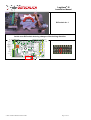
6.4.2.1 Anti Pass-Back Logic
Represents a logic that generates the feedback "passage finished" only when both the turnstile was rotated
and the person has gone through the sensors in the same time frame. For this function additional sensors are
required, which must be installed in the turnstile.
Practical use: when determining via the software of the reading system undoubtedly that a person is within
the protected area, or outside, e.g. time tracking, emergency evacuation, etc.
Feedback via relay AMP1 for entry direction and AMP2 for exit direction, can be set via Parameter 28
and 29 with value 81
Item no.
Component
Illustration
Anti-Passback Logik
2PV14-N
Anti Pass-Back Logic
Notwendige Bedingungen für
Inter-Sequenz-Überlappungen !
1.Durchgang
DF
EF/DF
Flag-Sequenz
für APB-Puls
EF (Rücknahme EF
durch Drehbewegung)
Sen3/4
SIN
SIN
≤≤ 10s
Drehbewegung
≤5s
≤≤
Timeout-Bedingungen !
SIN +
MOT
MOT
Mögliche Überlappungen in einer Sequenz !
Sen4/3
SIN +
MOT +
SOUT
SOUT
0,1...0,9s
APB_Puls !
APB-Ausgang (AMP1/2)
Löscht Flags vom 1.Durchgang !
Behält Flags vom 2.Durchgang !
Überlappender 2.Durchgang !
DF
EF/DF
EF (Rücknahme EF
durch Drehbewegung)
Sen3/4
≤≤ 10s
Drehbewegung
Sen4/3
SIN +
MOT +
SIN2
SIN2
≤5s
≤≤
SIN +
MOT +
SIN2 +
MOT2
MOT2
SIN2 +
MOT2 +
SOUT
SOUT
0,1...0,9s
APB_Puls !
APB-Ausgang (AMP1/2)
© Karl Gotschlich Maschinenbau GesmbH
Page 40 of 54
Logiturn® III
Installation Manual
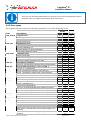
6.4.3 Factory settings
Par
Designation
Pri
ECCO FULL-HEIGHT TURNSTILE
Unit
0
1
2
3
4
5
6
7
8
9
10
11
12
13
14
15
16
17
18
19
20
21
22
23
24
25
26
27
28
29
Parameter set ID
Configuration
Max. speed 1
Max. speed 2
Max. motor speed
Min. motor speed
Acceleration time
Start distance
Stop distance
Interval
Repeat time
Rated current
Home position correction
Operating mode magn. brake
Division factor
Not in use
------------------------------------------------------------------------------------------------Input B (entry direction)
Input C (exit direction)
Input E (entry direction)
Input F (exit direction)
Input G (stop entry)
Counter output A
Counter signal duration
Alarm output
Relay output AMP1
Relay output AMP2
9
5
3
3
3
3
3
1
5
3
5
3
3
3
5
1
1
1
5
1
3
3
3
3
3
3
3
3
3
3
rps
rps
rps
rps
1/100 sec.
Pulses
Pulses
1/10 sec.
1/10 sec.
1/10A
Pulses
1/10 sec.
°
°
Pulses
1/100 sec.
-
© Karl Gotschlich Maschinenbau GesmbH
4-arm
(90°)
3-arm
(120°)
2-arm
(180°)
99
12
09
17
25
5
50
1
95
3
30
15
50
2
18
0
0
0
0
0
20
20
10
10
20
21
20
0
0
10
99
12
11
17
25
5
50
1
95
3
30
15
50
2
18
0
0
0
0
0
20
20
10
10
20
21
20
0
0
10
99
22
11
17
25
5
50
1
95
3
3o
15
50
2
18
0
0
0
0
0
20
20
10
10
20
21
20
0
0
10
Page 41 of 54
Logiturn® III
Installation Manual
Designation
30
31
32
33
34
35
36
37
38
Pri
Par
ECCO FULL-HEIGHT TURNSTILE
Unit
4-arm
(90°)
3-arm
(120°)
Relay output RM1
3
0
0
Relay output RM2
3
10
10
Relay output RM3
3
80
80
Relay output RM4
3
90
90
IR autostart
3
11
11
IR start criteria
3
0
0
Not in use
3
0
0
------------------------3
0
0
Braking profile
11
11
Battery operation (emergency
39
3
0
0
power mode)
40 Not in use
0
0
41 ------------------------0
0
42 ------------------------0
0
43 ------------------------0
0
44 ------------------------0
0
45 ------------------------0
0
46 ------------------------0
0
47 ------------------------0
0
48 Signal light model
3
0
0
49 Lane signal model
3
0
0
50 Input K, special function
3
0
0
51 Input L, special function
3
0
0
52 Reserve
0
0
53 --------------------0
0
54 --------------------0
0
55 --------------------0
0
56 --------------------0
0
57 --------------------0
0
58 Event recording 1
5
255
255
59 Event recording 2
5
255
255
Pri: Level of access authorization (see hardware control panel description)
© Karl Gotschlich Maschinenbau GesmbH
2-arm
(180°)
0
10
80
90
11
0
0
0
11
0
0
0
0
0
0
0
0
0
0
0
0
0
0
0
0
0
0
0
255
255
Page 42 of 54
Logiturn® III
Installation Manual
Parameter lists with factory settings are included in the turnstile housing. Any changes to parameters
should be entered into the list by hand.
6.5 Errors and warnings
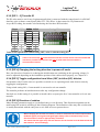
6.5.1 LED error indicator:
When an error occurs, the status LEDs (green area) indicate the error number and error source in binary
code, alternating in a four-second cycle.
Status LEDs
The error number and source are determined by adding the numbers indicated by the lighted LEDs
according to the following diagram:
LED no. 8 lit = error number displayed,
displayed
LED no. 8 not lit = error source is displayed.
LED display of error number and error source
© Karl Gotschlich Maschinenbau GesmbH
Page 43 of 54
Logiturn® III
Installation Manual
The errors are also represented directly in plain text on the control panel display and are
therefore easier to recognize than directly at the control unit.
6.5.2 Error types
The Logiturn turnstile control unit interrupts operation in case of the following errors:
Error
Type
Description
ERR_PROG Program error
No.
Initialization error
2
Error when saving parameter in flash
Error during loading parameter from flash
Error during operation
Error of end sensors ES_1, ES_2 or ES_3
Error of the speed detector or direction sensor
A
A
A
2
C
1
2
3
4
5
6
M
M
M
M
A/M
C
Gear belt broken
A
Motor error
Motor short circuit (cutoff by short circuit hardware)
Motor overcurrent (with CW movement) during initialization
Motor overcurrent (with CCW movement) during initialization
No or too little motor current (motor might not be connected)
Motor driven in CCW direction only (H bridge AH/BL poss.
defective)
Motor driven in CW direction only (H bridge BH/AL poss.
defective)
© Karl Gotschlich Maschinenbau GesmbH
1
2
3
4
5
6
A
C
-
1
D
1
2
3
4
E/A
F
F
G
A
6
No pulses, no end sensors, low motor current
ERR_MOT
1
250
255
5
No signal change from direction sensor during CW/CCW
pulses in initialization run
Problem with speed detector
More than 12 flanks detected during rotation movement
Evaluation only during manufacturers final inspection
Evaluation only during manufacturers final inspection
Evaluation only during manufacturers final inspection
ERR_ZR
A
B/L
B
J
4
Error ES_2 – ES2 defective
No ES_2 signal after 2 rotations - ES2 defective
No ES_1 signal after 4 edges of ES_2-ES1 defective
ES 1 defective
Neither ES1 nor ES2 flanks are detected, both ES defective
Pulse number too high for 1 rotation movement ( > 750)
ERR_DG
1
2
3
10
3
More than 100 impulse movements during locked turnstile
ERR_ES
A
G
A
Parameter error
Invalid configuration
ERR_OP
1-5
6
7-15
1
Invalid board ID (>99999999)
Timeout initialization run
Timeout release run during initialization
Undervoltage detection trigged
ERR_PAR
To-do
A
0
Internal system error
Defective motor
Internal system error
ERR_INIT
Source
7
5
A
6
Page 44 of 54
Logiturn® III
Installation Manual
Direction of rotation is wrong, only during manufacturers
final inspection
ERR_IMOT
Error of motor current measurement
H
7
8
MB test: abnormally high motor current measured
ERR_MB
Magnetic brake error
Little pulse, no end sensors, high motor current in CW
Little pulse, no end sensors, high motor current in CCW
During release movement in initialization run
A
1
xx
I
1
2
3
4
F
F
F/K
9
The magnetic brake yields to the motor power!
Indicates the power at which the brake fails in %
ERR_BLOCK Turnstile lock
1
10
CW…. Clockwise rotation direction
CCW…Counterclockwise rotation direction
6.5.3 Troubleshooting
When an error occurs, the turnstile must be switched off and then back on after 15 seconds. You can also
press the "RESET" button on the operating panel to restart. The turnstile then performs the test (diagnostic)
and initialization runs. Please note that the error message must be evaluated by a visual check in any case. If
the error message recurs, proceed according to the following information (see "To-do ID from the error type
list").
6.5.3.1 To-do lists
To-do
A
B
C
D
E
F
G
H
I
J
K
L
M
REMEDIAL ACTION
Defective drive; if repeated replace drive
Repeat initialization run and ensure that the turnstile mechanism can
turn freely.
General error message during operation. The results of the test run give
more detailed information as to the cause of the error.
Check the gear belt and replace if necessary.
Motor causes short circuit, replace drive motor if error message repeats
The turning arms or gear mechanism is blocked. Switch off the turnstile
and turn the arms manually. Possible causes of the error: Floor support
is difficult to turn, height of turnstile incorrectly adjusted during
installation (mechanism cannot move freely on the pin). Replace the
mechanism, if it is difficult to turn or locks up.
Check the cable connection with the drive motor. If no problem is
found, replace the drive motor.
Reverse motor cable polarity.
Check cable connection to magnetic brake, replace drive motor unit
with magnetic brake, if necessary.
Supply lines, check ratio of cross section to line length. Check contacts
on the power supply, the supply voltage drops below the critical value
during loads.
DIP switch 4 is wrongly set; refer to Chapter 4.2.
Bridge between ES1 and ES2 missing on 3*120° turnstile
Check the respective end switch and replace, if required.
Should the gearbox cover plate be removed, making moving parts accessible, the following applies:
© Karl Gotschlich Maschinenbau GesmbH
Page 45 of 54
Logiturn® III
Installation Manual
Danger: Danger caused by rotating parts. Disconnect the device from the power supply
when working in close proximity of these parts.
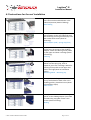
6.5.3.2 Replacement parts
Item no.
3P505-N
3P507-N
3P509-N
Component
Worm gear Logiturn ECCO 4*90°
Worm gear Logiturn ECCO 3*120°
Worm gear Logiturn ECCO 2*180°
3P040-N
Drive motor with gear pin and magnetic
brake
31057
Proximity switch
3P024-N
Gear belt LT incl. Allen wrench
3P025-N
Gear belt LT
3P530-N
Gear belt 960 ECCO
30mm belt width
© Karl Gotschlich Maschinenbau GesmbH
Illustration
Page 46 of 54
Logiturn® III
Installation Manual
6.5.4 Warnings
Warning messages can be seen as evidence of unusual operating conditions, the function of the turnstile is
carried out without restriction. The warning message includes the warning number and source of the
warning, thus indicating exactly what triggered the warning. The warning message is displayed cyclically;
this display can be switched off by pressing the reset button. Warnings are displayed on the hardware
control panel or at the software user interface.
No / Src
5
5 / P.no.
5 / 60
6
6/1
8
8/1
9
14
15 / 1
Warning / Source
Parameter warning /
parameter number
Invalid par. no.
Internal warning
Explanation
Parameter outside limits or invalid (P0 - P59) or
parameter no. too large >60
Invalid error number (>= 16)
Emergency power
operation
No initialization run
Device is externally
powered
Blockage
© Karl Gotschlich Maschinenbau GesmbH
BATTERY switched on
Init. run deactivate DIP 7=OFF
Turnstile is not ready for operation
No voltage supply, turnstile is manually powered.
Turnstile blockade with alarm state. Turnstile cannot
be in escape route position.
Page 47 of 54
Logiturn® III
Installation Manual
7 Hardware controls
7.1 Turnstile control unit
7.1.1 Block schematic diagram
Logiturn control board HW7 block diagram
Verbindung zum Erw. Print = connection to expansion board
Strombegrenzung = current limiting, Rot
R = red, Grün=green,
Spannungsversorgung = voltage supply, Erw.
E w. Print = expansion board, Serrielle Daten = serial data,
Motorbrücke = motor bridge,
Treiber/Decoder/Eingangsstufe = driver/decoder/input level
Lichttaster Eingänge
nge = light sensor inputs
Magnet bremse = magnetic brake, Elektromagnet= electromagnet, Zaehlerausgang=counter output,
Alarmausgang = alarm output,
Kontak-Eingaenge
Eingaenge = contact inputs, Drehwinkelsensor= angle position sensor, Alarmausgang=alarm output,
output
Spur=lane
© Karl Gotschlich Maschinenbau GesmbH
Page 48 of 54
Logiturn® III
Installation Manual
7.1.2 Control board (layout for HW rev.4)
Masse = Ground = GND
© Karl Gotschlich Maschinenbau GesmbH
Page 49 of 54
Logiturn® III
Installation Manual
24V~
0V~
GND
RX/TXRX/TX+
5
4
3
2
1
0V~ out
24V~ out
AMP1/NO
AMP1/COM
AMP1/NC
AMP2/NO
AMP2/COM
AMP2/NC
8
7
6
5
4
3
2
1
1
2
3
4
5
6
7
8
9
10
11
12
Si
6,3AT
X01A
X01B
MOT+
MO
O +
MO
MOTOTBR+
B
+
BRR-R
+24V
4V
V
GND
G
ND
N
D
DG
DG
RII
R
+24V
+
244V
V
ES1
ES1
S1
ES2
E
S22
AMP1
AMP2
X02
X03
12
11
10
9
8
7
6
5
4
3
2
1
DIP SWITCH
X
X10
X08
X07
24V~
0V~
GND
RX/TXRX/TX+
X19
X1
1
S2
S2
X18
X1
1
S1
X177
L22
L
X16
X04
X04
EMQ+
Q+ 4
EMQQ- 3
ALARM
RM
M 2
GND
G
ND
N
D 1
L
L1
X05
X
0
X06
ON
OFF
1 2 345 67 8
S
Sen4
Sen2
en Sen1
n1 Sen3
1 24V
1 Senx
1 Sigg 1/2
1 GND
X13
OUT A
GND
GND
+24V
+24V
COM BC
B
C
COM EFG
E
F
G
5
4
3
2
1
Sen
Assignment of the sensor connections sensor 1 to sensor 4
7.1.3 Connection terminals
The following table lists all types of inputs and outputs leading out from the metal housing of the turnstile
for power supply or signal and communications lines.
External terminals:
Terminal No. Connection
1
RTX+
X01a,b
2
RTX3
Ground
4
0V~
5
24V~
1
AMP2/NC
X02
2
AMP2/COM
3
AMP2/NO
4
AMP1/NC
5
AMP1/COM
6
AMP1/NO
7
24V ~ out
8
0V ~ out
1
OUTA
X03
2
GND
3
GND
4
+24V
5
+24V
6
COM BC
7
B
8
C
9
COM EFG
10
E
11
F
12
G
© Karl Gotschlich Maschinenbau GesmbH
Function
Interface RS485
Interface RS485
Ground connection
Power supply
Power supply
Signal light relay 2
Signal light relay 2
Signal light relay 2
Signal light relay 1
Signal light relay 1
Signal light relay 1
Power supply
Power supply
Counter output
Optical coupler supply
Optical coupler supply
Optical coupler supply
Optical coupler supply
Reference point logical
inputs
Release input
Entry direction
Release input exit
direction
Reference point logical
inputs
Release input
Entry direction
Release input
Exit direction
Release input
Stop function
Note
Shield connection
Normally closed
Contact root
Normally open
Normally closed
Contact root
Normally open
For signal lights, etc.
For signal lights, etc.
Transistor output
Shared reference point for
B/C
Optical coupler input
bipolar
Optical coupler input
bipolar
Shared reference point for
E/F/G
Optical coupler input
bipolar
Optical coupler input
bipolar
Optical coupler input
bipolar
Page 50 of 54
Logiturn® III
Installation Manual
Internal terminals:
Terminal No. Connection
1
Es3
X04
2
Es2
3
Es1
4
+24V
5
RI
6
DG
7
GND
8
+24V
9
BR10 BR+
11 Mot12 Mot+
1
GND
X05
2
Alarm
3
EMq4
EMq+
1
+24V
X07
2
Sen1
3
4
GND
1
+24V
X08
2
Sen2
3
4
GND
1
+24V
X09
2
Sen3
3
4
GND
1
+24V
X10
2
Sen4
3
4
GND
1
Vamp
X16
2
Red
3
Green1
4
Green2
1
Vamp
X17
2
Red
3
Green1
4
Green2
1
Vamp
X18
2
Red
3
Green1
4
Green2
1
Vamp
X19
2
Red
3
Green1
4
Green2
© Karl Gotschlich Maschinenbau GesmbH
Function
Ext. end sensor 3
Ext. end sensor 2
Ext. end sensor 1
Sensor power supply
Input direction
Input pulse generator
Sensor power supply
Magnetic brake
Magnetic brake
Motor connection
Motor connection
Alarm output
Alarm output
Holding magnet
Note
24V entry
24V entry
24V entry
24V entry
24V entry
Ground connection
Semiconductor output
H motor bridge
H motor bridge
Ground connection
Semiconductor output
GND connection for EM
Semiconductor output
IR sensor 1
Sensor input
IR sensor 2
Sensor input
IR sensor 3
Sensor input
IR sensor 4
Sensor input
Signal light L1
Symbol red X
Symbol green <
Symbol green >
Signal light L2
Symbol red X
Symbol green <
Symbol green >
Lane signal S1
Symbol red X
Symbol green <
Symbol green >
Lane signal S2
Symbol red X
Symbol green <
Symbol green >
+24V, Imax = 0.5A
Switch outputs
against GND
+24V, Imax = 0.5A
Switch outputs
against GND
+24V, Imax = 0.5A
Switch outputs
against GND
+24V, Imax = 0.5A
Switch outputs
against GND
Page 51 of 54
Logiturn® III
Installation Manual
7.2 Expansion board
An expansion board is available for tasks such as additional feedback outputs, an RS-232 interface and an
emergency battery power supply.
A detailed manual is available for the installation and commissioning. "Logiturn expansion
board"
Item
Designation
no.:
2P404-N EXPANSION BOARD M
Note
4 relay outputs,
Battery charger and RS-232
2P405-N EXPANSION BOARD E
4 optical coupler outputs,
Battery charger and RS-232
8P416-N UPS 2.1Ah for LOGITURN 2
Includes 2P404-N, and emergency power of 4h
8P406-N UPS 10Ah for LOGITURN 2
Includes 2P404-N, and emergency power of at
least 10h
3P321
BUFFER BATTERY 2.1Ah for Replacement battery pack
LOGITURN 2
3P330
BUFFER BATTERY 10Ah for Replacement battery pack
LOGITURN 2
7.3 Control panel
See 5.4.2
The detailed operating instructions "Hardware control panel for turnstiles" are available for
information on the installation and commissioning of the HWCP.
A separate "User manual" is available for the operating personnel to provide information for
operating.
© Karl Gotschlich Maschinenbau GesmbH
Page 52 of 54
Logiturn® III
Installation Manual
8 General troubleshooting
8.1 Semiconductor outputs are not functioning:
The PROFETs (transistors for counter outputs, e-magnets, and alarm outputs) may be deactivated
connected devices and wires for short circuit or overload (max. 0.25A)!
Check
8.2 Problems during turnstile startup
Error messages or unexpected rotations occur during the diagnostic and test runs:
•
Read error message via display on the control panel or via the LEDs on the control board, acc. to
6.1.5. Evaluate error according to description under 6.5.2 and proceed acc. to To-do list 6.5.3.1
•
Check whether the parameter set, particularly the configuration set up in the parameter set, is correct
for the device hardware. The control unit can be operated only with the corresponding mechanism.
If that is not possible, the control must be replaced.
•
The turnstile does not stop in the expected zero position. Check, if the turnstile flange is correct, bolt
acc. to installation step 13.
8.3 Problems with communication
8.3.1 RS-485 interface
Gate offline (turnstile does not respond):
•
ID on DIP switch is set incorrectly. See 6.3.2
•
ID on software or hardware control panel is set incorrectly. Par. no. 60 on the control panel is
responsible.
•
Baud rate is wrongly set (only possible on SW control panel), visible and correctable in service
mode.
•
COM port is wrongly set (only possible on SW control panel).
Is visible and correctable in service mode. The COM port must be adjusted to every port to which
the RS-232/RS-485 or USB/RS-485 converter was installed. Visible in the device manager.
•
RS-485 RX and TX data line connections are reversed (cables must be properly connected to the
right terminals).
•
Interface converter or control panel connected with 24 VAC voltage instead of the data lines.
Correct wiring; the converter or control panel interface may already be damaged.
•
Two control panels are connected to one turnstile. Only one CP per turnstile is permissible.
8.3.2 Problems with the test runs
Motor test and endurance run are not functioning:
Turnstile test mode has been canceled (e.g., with a reset). Switching on the "Service" operating mode and
entering the respective test run is required.
© Karl Gotschlich Maschinenbau GesmbH
Page 53 of 54
Logiturn® III
Installation Manual
9 CE Declaration of Conformity
Type of Machinery
Full-height turnstiles of the product designation:
ECCO ARENA.GATE Single, ECCO ARENA.GATE Double, ECCO 90 xxx,
ECCO 120 xxx, ECCO 180 xxx, ECCO ARENA.
According to specifications on the type label
Serial no.: 2130001.....2132000 = order number- 01.....99 = sequential no.
Year of manufacture: acc. to type plate
Date of delivery: acc. to type plate or delivery note
The manufacturer:
Karl Gotschlich Maschinenbau GesmbH
Feistlgasse 6, 1210 Vienna, Austria
Phone 0043/1/259 65 18
Fax 0043/1/259 65 18 6
The signee hereby declares that the product named above, in the design introduced into circulation by us,
corresponds to the provisions listed below as of the delivery date. This declaration is not valid if changes
have been made without prior consultation with us. The above mentioned products have been labeled with
the CE marking on the turnstile type label.
Applied harmonized guidelines and standards:
Appendix I of the EU Machinery Directive 2006/42/EG idgF
Appendix I of the Machinery Safety Regulation (MSV 2010) BGBI. II No. 282/2008 idgF.
EMC Directive 2004/108/EC
Low Voltage Directive 2006/95/EC
EN ISO 12100, EN ISO 13850, EN ISO 13857, EN 349, EN 953, EN 954-1, EN 1088,
EN 60204-1/07 (Pkt. 5,6,7 u 10), DIN EN 292-1, DIN EN 292-2, DIN EN 292-2/A1, DIN EN 1037, DIN
EN 1050, DIN EN 55011, DIN EN 60335-1, DIN EN 61000-3, DIN EN 61000-3-2, DIN EN 61000-3-3,
DIN EN 61000-6-1, DIN EN 61000-6-2, DIN EN 61000-6-3, DIN EN 61000-6-4, EN 55014-1, EN 550142, protection category IP44 of all line voltage parts and IP43 of housing acc. to EN 60529
Karl Gotschlich Maschinenbau GesmbH
Vienna, January 15, 1013
© Karl Gotschlich Maschinenbau GesmbH
Ing. Andreas Wotke
Managing Director
Page 54 of 54