1
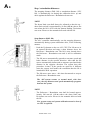
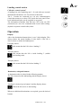
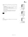
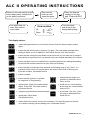
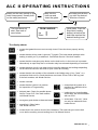
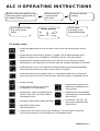
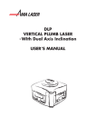
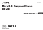
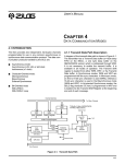
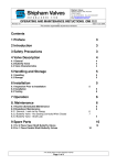
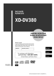
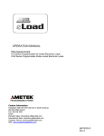
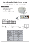
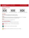
Alimak Lift Control, ALC II
User’s Manual
This manual is only applicable if the manufacturing number indicated below corresponds to the manufacturing number stamped on the identification
sign of the equipment. Where there is a conflict contact your ALIMAK representative.
YOUR HOIST HAS:
Manufacturing No.:
Year:
If the bottom right corner of this book is cut, the book is only valid for illustrative use!
Art. No. 9081541 - 1 04
2005 - 11 - 04
Photographs and drawings are illustrative only and do not necessarily show the design of the products on the market at any given point in time.
The products must be used in conformity with applicable practice and safety regulations. Specifications of the products and equipment
presented herein are subject to change without notice.
A0
ALIMAK LIFT CONTROL, ALC II
Alimak Lift Control, ALC II .........................
Semi-automatic control system.......................
Collective control system ...............................
Factory calibration .........................................
Stop / retardation distances ...........................
System set-up .................................................
Installation ......................................................
Information and fault indications on displays
Programming ..................................................
A1
A2
A2
A6
A8
A 10
A 14
A 15
A 16
A 30
ALC FOR CONSTRUCTION HOISTS
Control stations for construction hoists ....... A 30
Operation ........................................................ A 34
A 36
ALC II FÖR PERMANENTHISSAR
Tryckknappar och display i hisskorg ........... A 36
Operation ........................................................ A 37
ALC II ADAPTED FOR AUTOMATIC
DOORS
Programming of landings for
lifts with automatic doors ............................. A 38
Operating instructions and fault ....................
indications on displays ....................................
Collection of illustrative examples ...............
ALIMAK 34815 -1 /04
A1
Alimak Lift Control, ALC II
Alimak lift control, ALC II, is the name of Alimak’s modular
controller. The ALC system consists of a microprocessor based
controller, equipped with a high speed pulse counter input and a
pulse encoder. The position of the lift / hoist is determined by
counting impulses generated by the pulse encoder attached to
the drive unit.
To establish a reference point, a reference cam is attached to the
mast. When travelling in the calibration mode, the controller
receives the reference points by means of a limit switch
attached to the car.
The prime components of the controller system is one main unit
and two expansion units.
The main unit consists of a car CPU and one I / O-card (11
inputs / 7 outputs) in a common enclosure.
The car CPU has input for a pulse encoder and connections for
destination and communication (2-wire).
One I / O-card, same as the one in the main unit, is placed in a
separate enclosure to be used as expansion unit (maximum 1).
The concept behind this modular system is that the main unit
will control the lowest range of lifts. The system can expand in
one step by adding an expansion unit and thereby be able to
control most of the standard lifts and their equipment.
Control systems
In the main software there are two different control systems
available:
Semi automatic ...
... and Collective
The ALC II system automatically selects the control system.
ALIMAK 34184 -1/01
Pulse encoder
A2
Semi-automatic control system: (Stop Next Landing)
This is the least complex used control system available in the
ALC controller and operates without any landing cams. The
position of the lift is determined by counting impulses
generated by the pulse encoder attached to the gear box.
The lift can be operated push-buttons or with joystick from
inside the car and if chosen, also from the landings by using Up,
Down and Stop Next Landing push-buttons.
Push buttons on
landing control station
With the joystick, or by pressing a button for Up or Down, the
car starts travelling in the chosen direction. When the car
approaches the desired landing, the button Stop Next Landing is
pressed. The car will then stop automatically at the landing.
Calls / destinations from a landing box unit with Up, Down and
Stop Next Landing push-buttons operate on 230 VAC control
wires between the car and the landings via the base panel. A
destination order from the car has three seconds’ priority over
landing calls.
Collective control system:
This is the most advanced control system available in the ALC
controller. The lift can be operated from inside the car and if
chosen, also from the landings. Each landing is provided with
two call buttons, one for each travel direction.
There are two means of operating the lift from inside the car:
By destination push-buttons – one for each landing (perm. lifts).
By keypad (construction hoists).
This system receives all destination orders from inside the car,
as well as calls from the landings. The information is memorized and processed within the system.
ALIMAK 34817 -1 /04
A3
During the travel the lift will automatically stop at all floors,
which have been addressed.
If operation from inside the car is done by means of the keypad,
access to the Stop Next Landing control system is automatic.
The keypad is consisting of 15 push-buttons. 12 of them are for
the collective system: 0 – 9, ENT and CLR. The other three
push-buttons are for the Stop Next Landing system: Up, Down
and Stop Next Landing, which operates in parallel with the
collective system.
Keypad panel inside the car appl. for construction hoists
On every landing there is one I / O-card with two external
illuminated call buttons: one for each travel direction and one
indicator lamp: Out of service.
The I / O-cards are connected to a six wire communication
circuit that terminates in a base CPU inside the base panel. The
information is transmitted from the base CPU to the car CPU
(main unit) on a two wire communication circuit in the trailing
cable.
.
Indication lamp
’’Out of service’’ for
construction hoists only
ALIMAK 34818 -0 /01
Push button panel inside the car
applicable for permanent lifts
For permanent lifts only,
optional display at each landing
A4
ALC II additional features
Auto return, Authorized drive, Flood alarm and High wind
speed are examples of features available in the ALC II system.
These functions can be chosen with the system’s normal set-up
procedures (page A 12 – A 13).
Auto return
Auto return means that the lift returns to its base location after a
certain delay in time. (1 – 7 min. possible to be set).
This function is set in GROUP 8 – and will be activated when
time is chosen and set. Base location is normally the base
landing (0) and this does not need any further setting. This can,
however be changed in GROUP 10 – 13 to another landing
level, if desired.
Example: Base location on landing level 3.
Set Group 10. VALUE V1 + V2 = landing level 3.
Authorized drive
Authorized drive means for example that a crane operator via a
signal to the I/O-card at the base landing can address the lift to
the base location and also delete all other calls and destinations
– until the same person unlocks the lift.
Set this funtcion in GROUP 5, VALUE 1.
Base location is normally the base landing (0) and this does not
need any further setting. This can, however be changed in
GROUP 10 – 13 to another landing level, if desired.
Flood alarm
Flood alarm means that a signal from a trottle device
automatically addresses the lift to a level where the water
cannot reach.
Set this function in GROUP 5, VALUE 4.
Decide suitable level and set this in GROUP 10 – 13.
High wind speed
High wind speed means that the I/O-card in the base can receive
a signal from a wind speed meter and then automatically
address the lift to the base location and then also delete all calls
and destinations – until the wind speed will decrease.
Set this function in GROUP 7, VALUE 1
Base location is normally the base landing (0) and this does not
need any further setting. This can, however be changed in
GROUP 10 – 13 to another landing level.
Slipforming
Slipforming means that the lift will stop on temporarily
installed cams located on the moveable slipform.
The system receives continuously information where the lift is
located on the mast via input to the car CPU’s expansion unit.
The temp. installed cams are monitored by the ordinary normal
and final limit cams on the mast.
ALIMAK 34908 -1/04
1 instead of 0 at the base landing
This means that the system counts levels, starting from 1, 2, 3
instead of 0,1, 2. If this function is chosen all former
programmed levels in the system must be deleted.
Set this in GROUP 6, VALUE 1.
Base location in top
Base location in top means that the base CPU is connected to
the top landing instead of the bottom landing.
This is preferable for offshore lifts installed inside the oil rig’s
support leg.
Set this in GROUP 6, VALUE 2.
Explosion proof lifts
Explosion proof lifts require an extra ordinary configuration
with I/O-card containing push-buttons.
Set this in GROUP 15, VALUE 2.
High speed monitoring
High speed monitoring (according to demands in North
America) means that the lift will stop as soon as the preset value
for normal operation exceeds. The display inside the car will
then show F8. Value for maximum speed is preset and cannot be
changed.
Set this in GROUP 9, VALUE 2.
Fire alarm
Fire alarm means that a fire detecting device via a signal to the
I/O-card at the base landing can address the lift to the base
location and also delete all other calls and destinations – until
fire fighting personnel unlocks the lift.
Set this in GROUP 4, VALUE 1, 2 or 4 depending on
applicable regulations.
The lift will return to desired level chosen in GROUP 10 – 13.
Floating landing level
Floating landing level can detect via a signal to the I/O-card at
the base landing where the landing is located – even if the
landing level is changed. This feature is preferable for boiler
installed lifts where the whole structure can expand and move
compared with the entire lift installation.
ALIMAK 34409 -1/04
A5
A6
Factory calibration
(Normally done at the factory before delivery)
This system calibration drive is normally done at the factory at
delivery, but must be done once again if the car CPU is to be
replaced.
During the calibration drive the lift is running automatically up
and down 4 times to measure speed and then by itself calculate
the stopping distances.
IMPORTANT ! Lifting height needed for this purpose is
minimum 10 m at a speed of 0.70 m/s. More when higher
speed occurs.
The calibaration drive is done from inside the car and starting
from the bottom landing.
To put the system in system set-up / calibration mode is
done according to the following
– Disconnect the battery.
– Keep the Prog. button on the car CPU depressed and then
turn main power switch to ON position.
– Keep the Prog. button depressed until the LED SYS
CHK lights up (after 2 sec.).
Then continue pushing the Stop Next Landing button,
Down button and finally
the Up button.
Keep all 4 buttons depressed whereupon all 8 LEDs
for GROUP and VALUE start flashing.
– Release all buttons when the LEDs start flashing with
shorter intervals. The system is in calibration mode and all
parameters established in a basic set-up when the LEDs go
out.
The display shows:
System with dual display.
System with single display.
– Reconnect the battery
ALIMAK 34819/1 -1 /04
A7
If the base configuration is changed after the delivery from
factory due to more added landing stations, the LED V8 on the
car CPU starts lighting. This is fully normal and the intention is
only to indicate that there is a change made to the equipment.
If the reason is other than just more added landing stations a
new base configuration must be performed.
To replace the present base configuration proceed according
to the following:
– Disconnect the battery.
– Switch off the car main electrical panel.
– Switch off the base main electrical panel.
– Reset the base main electrical switch in ON position.
– Keep the Prog. button on the car CPU depressed and put the
main electrical switch in ON position.
– Continue keeping the Prog. button depressed and then push
the Stop Next Landing 2 (two) times.
– Finally release the Prog. button
The display shows:
(no landings are programmed into the system):
System with dual display.
System with single display.
– Reconnect the battery
Calibration drive is performed from inside the car, starting
from the bottom landing.
ALIMAK 34819/2 -1 /04
A8
Stop / retardation distances
The stopping distance (DOL lift) or retardation distance (VFC
lift), is automatically set during the calibration drive up and
down against the Reference / Retardation down cam.
NOTE!
The down limit cam shall always be adjusted so that the up /
down limit switch is approximately 10 mm (1/2 in.) above the
cam when the lift is level with the bottom landing. Deviations
can occur. Please see the manuals delivered with the lift.
Stop distances (DOL lift)
The ALC controller automatically sets the stopping distances,
automatically during system calibration drive, in the following
manner:
– Push the Up-button on the car ALC CPU. The lift moves in
an upward direction and stops a short distance above the
Reference / Retardation cam. The lift is now located above
the Reference / Retardation cam and is still in calibration
mode.
– The lift moves automatically upwards to measure speed and
brake distance in the upward direction. After that the lift
moves automatically downwards to measure speed and brake
distance in the opposite direction. The system does this
procedure 4 times. If the speeds are equal for 4 different
starts the system itself makes the conclusion that the lift is
intended for DOL opeartion.
– The lift moves once more – this time downwards to stop on
the Reference / Retardation cam.
The ALC-system returns to normal mode with door
zone, the stop distances and speed automatically programmed into the system.
NOTE!
– The Reference / Retardation cam shall be located approximately 240 mm (9 1/2 in.) above the down limit cam.
Deviations can occur. Please see the manuals delivered with
the lift.
New system set-up and system calibration must be done if
car CPU is replaced.
ALIMAK 34820 -0 /03
A9
Retardation distances (VFC lift)
The ALC controller sets the retardation distances automatically
during system calibration drive, in the following manner:
– Push the Up-button on the car ALC CPU. The lift accelerates
to nominal speed upwards.
When the Reference / Retardation switch leaves the cam, the
ALC controller removes the high speed signal and the lift
decelerates and stops.
The lift is now located above the Reference / Retardation
cam and is still in calibration mode.
– The lift accelerates automatically upwards to high speed,
retards and stops. Speed and retardation distance, from high
to low speed in upwards direction are now stored into the
system. The lift accelerates once more automatically
downwards to high speed, retards and stops. Speed and
retardation distance, from high to low speed in downwards
direction are now stored into the system.
– The system does this procedure 3 more times to measure 2
intermediate speeds and 1 low speed with corresponding
retardation distances.
The lift will stop on the reference cam after 4 times up and
down.
Retardation distances for 4 different speeds and the door
zone are now programmed into the ALC-system. This
system calibration is normally done at the factory.
If the lift is moving on crawling speed for approximately 2
to 10 cm (1 – 4 in.) before it stops, then the retardation
distance is Ok.
NOTE!
– The Reference / Retardation cam shall be located approximately 1.1 x Y m above the down limit cam. (Y= the lift
speed in m/sec.). Deviations can occur. Please see the
manuals delivered with the lift.
The lift should move on crawling speed for only approximately 2 to 10 cm (1 – 4 in.) when stopping at landing.
– If location of the reference cam is changed all landing levels
must be changed the corresponding way.
New system set-up and system calibration must be
done if car CPU is replaced
ALIMAK 34184 -1/03
A 10
System set-up
A system set-up has to be performed in order to prepare the
controller for the actual lift and its functions. Set-up is performed in the following manner:
– Switch off the main power.
– Disconnect the battery.
– Press on and hold Prog. button.
Note: The button must be kept depressed during the entire
set-up procedure.
– Switch on the main power. The system is now in set-up
mode.
On the main unit there are 2 locations with 4 LED indicators
in a row close to the push-buttons.
In system set-up mode the 4 LEDs indicate VALUE, V1,
V2, V4 and V8 in binary code. (LED ”sys. check” is flashing).
The 4 LEDs above indicate GROUP, G1, G2, G4 and G8 in
binary code. (LED ”SYS. CHECK” is illuminated).
The Up or Down buttons are used to select GROUP level.
The Stop Next Landing button is used to open and select
VALUE level.
Select VALUE with Up / Down buttons. Depress the Stop
Next Landing button to store VALUE level and the system
then will switch to GROUP.
– Set the binary code in accordance with the lift and its
functions, using the table on page A13.
– The value will be stored every time Stop Next Landing
push-button is depressed.
– Release Prog. button.
– Connect the battery. The system set-up is now completed.
See collection of illustrative examples at the end of this manual.
ALIMAK 34822 -1 /01
A 11
Car CPU (main unit)
ALIMAK 34823 -1 /03
A 12
ø = means LED ON
o = means LED OFF
Example 1:
Example 3:
Door close sequence set to nom, 9 sec.
Car to be addressed to landing B (level 18) automatically
with 5 min. delay.
GROUP 0
o
o
o
o
VALUE 9
ø
o
o
ø
V1 + V8 = 9 sec.
V8
GROUP 8 o
o
o
ø
VALUE 5
GROUP 12 o
o
ø
ø
VALUE 2
GROUP 13 ø
o
ø
ø
VALUE 1
ø
o
ø
ø
V1 + V4 = 5 min.
addressed to landing B
Example 2:
Car to be addressed to landing A (level 3) when high
wind speed occurs.
GROUP 7
ø
ø
ø
o
VALUE 1
GROUP 10 o
ø
o
ø
VALUE 3
ø
o
o
o
High wind speed
ø
ø
o
o
V1 + V2 = 3
(level 3 chosen)
ALIMAK 34906 -1/04
o
ø
o
o
ø
o
o
o
level 2
level 16 to be added
to level 2 (previous
group 12 above)
= level 18
A 13
GRP. Binary Decsription
code
VALUE
V8
V4
V2
V1
0
o
o
o
o
Door close
sequence
ø
o
o
o
ø = 1 – 15 sec.
ø
ø
ø
o
o
o
ø = 8 sec.
o
o
ø = 4 sec.
o
o
ø = 2 sec.
o
o
ø = 1 sec.
o
o
o
1
ø
o
o
o
Door 1
Solenoid / Actuator
*
*
*
ø EN load ramp
o
o
o
o
2
o
ø
o
o
Door 2
Solenoid / Actuator
*
*
*
ø EN load ramp
o
o
o
o
3
o
ø
o
o
Door 3
Solenoid / Actuator
*
*
*
ø EN load ramp
o
o
o
o
4
o
o
ø
o
Fire alarm
o
o
*
*
o
o
*
*
o
o
*
*
o
o
o
o
*
*
*
ø Landing
level B
*
*
ø AUS requirem.
*
ø
*
*
*
ø
*
ø Automatic door *
*
*
*
*
ø
*
ø Automatic door *
*
*
*
*
ø
*
ø US requirem.
*
*
*
*
*
5
ø
o
ø
o
Larm function o
o
o
o
*
*
*
ø Landing
level B
*
*
ø Flood alarm
*
*
ø
*
*
ø Permission to drive
*
*
*
6
o
ø
ø
o
Funtions
o
o
o
o
*
*
*
ø Floating
landing
*
*
ø Movable top
* landing
*
ø Base landing
* in Top
*
ø 1 instead of 0 at base
* landing
*
*
7
ø
ø
ø
o
Wind speed
o
o
o
o
*
*
*
ø Landing.
level B
o
o
o
o
o
o
o
o
ø High windspeed
*
*
*
8
o
o
o
ø
Autoreturn
*
o
o
o
*
*
*
ø Landing
level B
o
o
ø = 4 min.
o
o
ø = 2 min.
o
o
ø = 1 min.
o
o
o
9
ø
o
o
ø
o
o
o
o
o
o
o
o
o
o
o
o
o High speed
ø monitoring
o
o
ø Calibration
o ref. up.
o
o
10
o
ø
o
ø
Landing level o
A delay 1
o
o
o
o
o
o
ø Level 8
o
o
ø Level 4
o
o
ø Level 2
o
o
ø Level 1
o
o
o
11
ø
ø
o
ø
Landing level o
A delay 2
o
o
o
o
o
o
ø Top level
o
o
o
o
o
ø Level 32
o
o
ø Level 16
o
o
o
12
o
o
ø
ø
Landing level o
B delay 1
o
o
o
o
o
o
ø Level 8
o
o
ø Level 4
o
o
ø Level 2
o
o
ø Level 1
o
o
o
13
ø
o
ø
ø
Landing level o
B delay 2
o
o
o
o
o
o
ø Top level
o
o
o
o
o
ø Level 32
o
o
ø Level 16
o
o
o
*
*
*
ø SYS.CAL OK.
o
o
o
o
o
ø Ex. proof lift
o
o
o
o
o
o
14
15
ø = 1 – 7 min.
ø
ø
o
*
ø Automatic door
*
*
VACANCY
ø
ø
ø
ø
Authorized
ø Configuration for base
personnel only ø CPU
ø
ø
ALIMAK 34907 -1/04
Mec. interlock
.
Mec. interlock
.
Mec. interlock
.
EU requirem.
A 14
Installation
During erection of the lift – assembling mast sections, mast ties,
landing enclosures etc, turn the Norm. / Insp. switch to position
”Insp”. The lift is then manually controlled from the Inspection
push-buttons on the car roof.
Commissioning
All electrical equipment in the car is installed and wired at the
factory. It's a ’’ready to use package’’ requiring no further
assembly. The remaining installation of the system is performed
at the job site according to the following:
1. Install incoming power cable to the B panel in accordance
with the wiring diagram.
2. Install cable(s) between B panel and the car in accordance
with the wiring diagram.
3. Adjust the reference (retardation down) cam on the mast.
4. Check that all cams are correctly installed on the mast, both
on top and bottom, by travelling manually in the Inspection
mode.
5. Connect the landing control cable to the base panel and to
each landing unit in accordance with the wiring diagram.
6. The system is now ready for programming.
Information and fault indications on the car CPU
Group Normal mode
VALUE V1
V2
V4
V8
ø
ø
busy, car in operation
base OK (flashing)
ø
car/base OK (flashing)
ø base configuration fault
Group Normal & Status mode (push the Prog. button once)
VALUE V1
V2
V4
V8
ø
ø
movement
z-pulse
ø
direction upwards
ø occupied
Error mode (push the Prog. button once)
VALUE V1
V2
V4
V8
ø
ø
car configuration fault
motor alarm F6
ø
chek sequence F9 (lift not prepared)
ø calibration fault
Error & Status mode (push the Prog. button once more)
VALUE V1
V2
V4
V8
ø
ø
speed error F8
EN load ramp fault F3
ø
safety circuit switched off F1
ø interlock fault F3
Diagnose mode – flashing,
(Norm./Insp. switch in Insp. position)
VALUE V1
V2
V4
V8
ø
ø
GPRS modem
IP adress choosen
ø
TxIP (transmit)
ø RxIP (receive)
ALIMAK 34824 -1 /01
Information and fault indications on displays
Fault indications
A hoist / lift equipped with the ALIMAK ALC control system
and landing level display on the lift electrical panel has access
to a fault indication system. Faults indicated at the display are
the following:
Safety circuit broken
Door circuit open with hoist between landings
Fault in door closing sequence
Overload
Hoist in Inspection or in Programming mode
Hoist does not start within start time/ fault on
pulse encoder
Pulled in emergency stop button at base landing
Other fault
Fault in control circuit
Information
Door(s) open
Calibration drive
Inside car; Closed landing
At the base landing; connection to the car CPU broken
Landing circuits disconnected at the base level
(Operation from car only )
ALIMAK 34825 -1 /01
A 15
A 16
Programming
Calibration drive (CD) and deletion of all landings.
Before the programming of landings can start, the reference
point has to be established and since the lift could have been
used before, all previous landings that might be programmed
into the system, must be deleted.
In order to delete all landings the lift must be positioned at the
bottom level located on the reference cam and must be in the
calibration mode.
Activating calibration mode:
The lift is to be positioned at the bottom level located on the
reference cam with safety circuit in order and doors closed.
Press the Prog. button on the car CPU and keep it depressed.
The Prog. LED will be illuminated after approximately 3
seconds. Keep the Prog. button depressed and also press the Up
and Down button at the same time. Then release all buttons and
the Prog. LED goes out.
The display shows:
(if 5 landings are programmed into the system)
CD and 5 flash
alternately on the display
for the single system.
+
The lift is now in calibration mode.
Delete all landings:
The lift must be in calibration mode (see above) and positioned
at the lowest landing.
In order to delete all landings: press the Prog. button on the car
CPU and keep it depressed. The Prog. LED will be illuminated
after approximately 3 seconds. Keep the Prog. button depressed
and also press the Up and Down button at the same time. Then
release all buttons and the Prog. LED goes out.
The display shows:
CD flashes on the display
for the single system.
All the landings have now been deleted and the lift returns to
the calibration mode.
Calibration drive, CD
The intention with the calibration drive is to pick up reference
level.
ALIMAK 34827 -1 /04
Landings are NOT stored into system
Calibration drive from inside of the car when lift is located
at bottom landing:
The display shows:
(no landings are programmed into the system):
CD flashes on the display
for the single system.
– Press Up button and the lift will automatically start upwards
until it has left the reference cam and then it stops.
– The lift now automatically moves back down to the bottom
landing and stops on the reference cam.
The display shows:
The reference level is now programmed into the system.
The lift is now back into normal mode but no landings
are programmed into the system.
See page A 16, Programming of landings.
Calibration drive from inside of the car when lift is located
somewhere above the bottom landing:
The display shows:
(no landings are programmed into the system):
CD flashes on the display
for the single system.
– Press Down button and the lift will automatically start
downwards to the bottom landing and stops on the reference
cam. (”Ref. down” LED goes out).
The display shows:
The reference level is now programmed into the system.
The system is now back into normal mode, but no landings
are programmed into the system.
See page A 16, Programming of landings.
ALIMAK 34828 -1 /04
A 17
A 18
Landings ARE stored into the system
Calibration drive from inside of the car when lift is located
at bottom landing:
The displays show:
(if 5 landings are programmed into the system)
CD and 5 flash
alternately on the display
for the single system.
alternatively . . .
– Press Up button and the lift will move upwards until it has
left the reference cam and then it stops.
– The lift now automatically moves down to the bottom and
stops.
The reference level is now programmed into the system.
The system is now back into normal mode. Direct the lift to
the desired landing.
The display shows:
0 lights up on the display
for the single system.
. . . or ’’0’’ for
permanent lifts
Calibration drive from inside of the car when lift is located
somewhere above the bottom landing:
The displays show:
(if the number of programmed landings is 5)
CD and 5 flash
alternately on the display
for the single system.
ALIMAK 34829 -1 /04
A 19
– Press the Down button and the lift will go down to the
bottom and stop.
The reference level is now programmed into the system.
The lift is now back into normal mode. Direct the lift to the
desired landing.
The display shows:
0 lights up on the display
for the single system.
alternatively . . .
Calibration drive from landing or B-panel when car is
located at bottom landing:
– Press Call button and the lift will move upwards until it has
left the reference cam and then it stops.
– The lift now automatically moves down to the bottom and
stops.
The reference level is now programmed into the system.
The system is now back into normal mode. Direct the lift to
the desired landing.
Calibration drive from landing or B-panel when car is
located somewhere above the bottom landing:
– Press the Call button and the lift will go down to the
bottom and stop.
The reference level is now programmed into the system.
The system is now back into normal mode. Direct the lift to
the desired landing.
ALIMAK 34830 -1 /04
. . . or ’’0’’ for
permanent lifts
See separate section A38 – A48 for programming of
A 20
Programming of landings
The lift shall be in normal operation mode.
– Press the Prog. button inside the car electrical panel until the
PROG. LED is illuminated. The lift is now in programming
mode.
The displays show (if no landings are programmed into the
system):
F5 lights up on the display
for the single system.
+
– Run the lift with the Up and Down button inside the car
to the bottom landing level. Check that the lift has not
actuated the down limit switch when it is level with the
bottom landing. (The same goes for the top landing).
– Press the Stop Next Landing button.
The system will unlock the doors one by one.
Open suitable door for the landing in question. (If not, the
landing will be stored as a closed landing).
The Prog. LED goes out.
The first landing level is then programmed into the system
and the system returns to normal operation.
The display shows:
0 lights up on the display
for the single system.
To program the next landing, proceed in the following manner:
– Press the Prog. button on the car CPU until the Prog. LED
is illuminated. The lift is now in programming mode.
The display shows:
0 and 5 flash
alternately on the
display for the single
system.
+
– Run the lift with the Up and Down button inside the car to
the second landing level.
– Press the Stop Next Landing button.
The system will unlock the doors one by one.
Open suitable door for the landing in question. (If not, the
landing will be stored as a closed landing).
The Prog. LED goes out.
The second landing level is then programmed into the
system and the systemt returns to normal operation.
ALIMAK 34831 -1 /04
landings where automatic doors occurs
A 21
The display shows:
1 lights up on the display
for the single system.
Program additional landings into the system in the same manner.
NOTE!
– As soon as a landing is programmed into the controller it
unlocks intended door(s) on corresponding landings.
– If a VFC lift is in programming mode, then the driving speed
is very low in order to facilitate stopping at the landing level
intended to be programmed.
Should there be a longer distance between the landings it is
always possible to drive to the next landing in a higher
speed according to the following: Press the Up button and
wait until the car has left the landing door zone – then press
the Up button once again. The system will then automatically change to higher speed when running to the next
landing. Release the Up button and press the Stop Next
Landing button at the next landing level and the landing
level will be stored.
If the landing level needs to be adjusted, this must be done in
low speed mode.
Press Up-button once again
to achieve increased speed.
– It is not possible to program a new landing in-between two
existing landings.
Delete the top landing:
Run the lift to the top landing in Normal operation mode.
The display shows:
(if the top landing is No. 5)
5 lights up on the display
for the single system.
– Press the Prog. button on the car CPU and keep it depressed.
After approximately 3 seconds the Prog. LED will
illuminate. Then press Up and Down button at the same
time. Then release all buttons and the Prog. LED goes out.
The top landing level is now deleted and the system returns
to normal operation.
The display shows:
4 lights up on the display
for the single system.
ALIMAK 34832 -1 /04
+
A 22
Move / adjust a landing:
It is possible to move / adjust any landing level as long as the
adjustment stays within the original door zone. This is performed in the following manner:
– Move the lift to the actual landing in normal operation.
– Press the Prog. button on the car CPU inside the main panel
until the Prog. LED is illuminated. The lift is now in
programming mode.
The displays show (if the lift is on landing 5):
5 and F5 flash
alternately on the
display for the single
system.
+
– Run the lift with the up and down button inside the car
to the ”new” landing level.
– Press the Stop Next Landing button.
The system will unlock the doors one by one.
Open suitable door for the landing in question. (If not, the
landing will be stored as a closed landing).
The Prog. LED goes out.
The moved / adjusted landing level is then programmed
into the system and the system returns to normal operation.
The display shows:
5 lights up on the display
for the single system.
Change floor level indication
+
The floor level indication can be changed from digit to a letter.
For instance B, E, G, P or T.
This is performed in the following manner:
– Run the lift to the actual landing in normal operation.
– Press the Prog. button on the car CPU inside the main panel
until the Prog. LED is illuminated. The lift is now in
programming mode.
– Press the Stop Next Landing button.
The system will unlock the doors one by one. Open suitable
door for the landing in question and leave it open.
– Use the Up and Down buttons to change the floor level
indication.
When intended floor level indication is achieved – close the
door and the new floor level indication will be stored.
ALIMAK 34833 -1 /04
A 23
Close intermediate landings:
On a construction site intermediate landings can be made inaccessible, if desired. Instead of deleting those landings and
reprogramming the landings above, the landings can be locked
out in the control system.
This is performed in the following manner:
– Drive to the landing in normal mode (for example landing 4
of totally 8).
The display shows:
4 lights up on the display
for the single system.
– Press the Prog. button on the car CPU and keep it depressed
After approximately 3 seconds the Prog. LED will
illuminate. Then release the Prog. button and depress the
Stop Next Landing button.
Do not touch the doors when the system starts unlock the
doors.
The display shows:
4 lights up on the display
for the single system.
The 4th landing is now closed, all doors are locked and the lift
has returned to normal operation. Move the lift to an open
landing – for example landing 2.
2 lights up on the display
for the single system.
The permanent lift does not attempt to start if you try to destinate it to a ”closed” landing. The display for the construction
hoist will show an ”X” in this situation.
2 lights up on the display
for the single system.
ALIMAK 34834 -1 /04
+
A 24
Activating a closed landing:
Opening a closed landing is performed in the following manner:
– Run the lift in normal mode to the nearest landing, which
is open.
+
– Place the lift in Inspection mode or Prog. mode and move
to the closed landing level. Ensure that the car is located
within the door zone.
– Return it to Normal operation.
– Press the Prog. button on the car CPU inside the main panel
until the Prog. LED is illuminated. The lift is now in
programming mode.
+
The displays show (if the lift is on landing 4):
4 and F5 flash
alternately on the display
for the single system.
+
– Press the Stop Next Landing button. Open up and close the
car door where the intended landing is located. The Prog.
LED goes out. The closed landing is opened and the system
returns to normal operation.
The displays show (if the lift is on landing 4):
4 lights up on the display for
the single system.
Programming of passing through landings
Two push-button boxes at the same landing
+
ALIMAK 34835 -1 /04
A 25
The lift shall be in normal operation mode.
– Press the Prog. button on the car CPU inside the main panel
until the Prog. LED is illuminated. The lift is now in
programming mode.
The display shows
(if no landings are programmed into the system):
F5 flashes on the display
for the single system
– Run the lift with the Up and Down button inside the car
to the bottom landing level. Check that the lift has not
actuated the down limit switch when it is level with the
bottom landing. (The same goes for the top landing).
+
– Press the Stop Next Landing button.
The system will unlock the doors one by one.
Open suitable door for the landing in question. (If not, the
landing will be stored as a closed landing).
The Prog. LED goes out.
The first landing level is then programmed into the system
and the system returns to normal operation.
Note: do not operate the lift from this position.
The display shows:
0 lights up on the display
for the single system.
To program next door and push-button box proceed in the
following manner:
– Press the Prog. button on the car CPU until the Prog. LED
is illuminated. The lift is now in programming mode.
– Press the Stop Next Landing button and keep it depressed
while the Down button is pressed.
– Release the Stop Next Landing button and after that the
Down button.
The system will unlock the doors one by one.
Open suitable doors for the landings in question.
The display shows:
0 lights up on the display
for the single system.
NOTE !
If you have to adjust the landing levels the entire procedure
must be repeated.
ALIMAK 34836 -1 /04
+
A 26
Programming of two separate landings at the same
level with a landing push-button each
Landing
1
Landing
0
The lift shall be in normal operation mode.
+
– Press the Prog. button on the car CPU inside the main panel
until the Prog. LED is illuminated. The lift is now in
programming mode.
The display shows F5 = programming mode (if no landings are
programmed into the system):
F5 flash on the display
for the single system.
– Run the lift with the Up and Down button inside the car
to the bottom landing level. Check that the lift has not
actuated the down limit switch when it is level with the
bottom landing. (The same goes for the top landing).
+
– Press the Stop Next Landing button.
The system will unlock the doors one by one.
Open suitable door for the landing in question. (If not, the
landing will be stored as a closed landing).
The Prog. LED goes out.
The first landing level is then programmed into the system
and the system returns to normal operation.
Note: do not operate the lift from this position.
ALIMAK 34837 -1 /04
A 27
The display shows:
0 lights up on the display
for the single system.
To program the next landing, proceed in the following manner:
– Press the Prog. button on the car CPU until the Prog. LED
is illuminated.
– Press the Stop Next Landing button and keep it depressed
while the Up button is pressed.
– Release the Stop Next Landing button and after that the Up
button.
The system will unlock the doors one
Open suitable door for the landing in question.
by
one.
+
The display shows:
1lights up on the display
for the single system.
TEST !
Construction Hoist
Press 0 + ENT. The 1st car door will be unlocked. No car
movement will appear.
The display shows:
Press 1 + ENT. The 1st car door will be unlocked. No car
movement will appear.
The display shows:
Permanent Lift
Press 0. The 1st car door will be unlocked. No car movement
will appear.
The display shows:
Press 1. The 2nd car door will be unlocked. No car movement
will appear.
The display shows:
ALIMAK 34838 -1 /04
+
A 28
Programming of landings where NO push-button
box can be found at the landing level
The lift shall be in normal operation mode.
+
– Press the Prog. button on the car CPU inside the main panel
until the Prog. LED is illuminated. The lift is now in
programming mode.
The display shows F5 = programming mode (if no landings are
programmed into the system):
F5 flashes on the display
for the single system.
– Run the lift with the Up and Down button inside the car
to the bottom landing level. Check that the lift has not
actuated the down limit switch when it is level with the
bottom landing. (The same goes for the top landing).
+
– Press the Stop Next Landing button.
The system will unlock the doors one by one.
Open suitable door for the landing in question. (If not the
landing will be stored as a closed landing).
The Prog. LED goes out.
The first landing level is then programmed into the system
and the system returns to normal operation.
Note: do not operate the lift from this position.
The display shows:
0 lights up on the display
for the single system.
ALIMAK 34839 -1 /04
A 29
To delete function for push-button box proceed in the following
manner:
– Press the Prog. button on the car CPUl until the Prog. LED
is illuminated.
– Press the Stop Next Landing button and keep it depressed
while the Up and Down buttons are pressed.
– Release the Stop Next Landing button and after that the Up
and Down buttons.
The system will pull the door lock solenoids one by one.
Open suitable door for the landing in question.
+
The display shows:
0 lights up on the display
for the single system.
NOTE !
If you have to adjust the landing levels
the entire procedure must be repeated.
+
ALIMAK 34840 -1 /04
A 30
ALC II for Construction Hoists
Control station in the car
Semi-automatic control:
The control station front includes as standard :
– Joystick for Up and Down and an additional
Stop Next Landing push-button (The Stop Next
Landing button is illuminated).
– A 2-digit display, showing current landing,
fault indication and information.
– Emergency stop push-button.
– An alarm push-button.
– A switch for light in car.
As an option overload indication lamp can be
furnished.
On the inside of the control panel:
– Push-button on the car CPU
– Norm. / Insp. selector switch.
Top of car control:
Top of car control consists of:
– Up and Down push-button.
– An Emergency stop push-button.
ALIMAK 34184 -1/04
A 31
Collective control:
The control station includes as standard on the front:
– A keypad with 15 push-buttons: 0 – 9, ENT,
CLR, Up, Down, Stop Next Landing.
– Two 2-digit displays, one showing current
landing and the other showing next stop, fault
indication and information.
– Emergency stop push-button.
– An alarm push-button.
– A switch for light in car.
As an option overload indication lamp can be
furnished.
On the inside of the control panel:
– Push-button on the car CPU
– Norm. / Insp. selector switch.
Top of car control:
Top of car control consists of:
– Up and Down push-button.
– An Emergency stop push-button
ALIMAK 34842 -1 /01
A 32
B-panels
Car operated hoist:
The B panel is not equipped with any control push-buttons. It
can be combined with both Semi-automatic or collective car
control.
Semi-automatic control system:
This B panel is equipped with Up, Down and Stop Next
Landing push-buttons.
The signals from the push buttons transmit through 230 VAC
control wires between the main panel and the base panel and
also to the landing control boxes.
Collective control system:
This B panel is equipped with one I/O-card, one ”Car only”
selector switch and one externally illuminated call button.
On the front of the B panel a 2-digit display is available
showing the actual position of the hoist, but also information /
fault indications.
The I / O-cards are connected to a six wire communication
circuit that connects to a base CPU inside the base panel out to
the landing control boxes.
The selector switch ”Car only” (marked -S 107) disconnects all
signals from the landings, which means that the lift can only be
operated from inside the car.
From the base CPU to the car CPU (main unit) the information
transmits through a two wire communication circuit in the
trailing- (hybrid) cable.
ALIMAK 34843 -1 /01
A 33
Landing control equipment
Semi-automatic control system:
A landing box unit with Up, Down, and Stop Next Landing
push-buttons.
The signals from the push-buttons transmit through 230 VAC
control wires between the landings and the main panel via the
base panel
Push buttons on
landing control station
Collective control system:
A landing box unit containing one I / O-card with two external
illuminated call buttons: one for each travel direction and one
indication lamp: ”Out of service”.
The I / O-cards are connected to a six wire communication
circuit that connects to a base CPU inside the base panel.
The information transmits from the base CPU to the car CPU
(main unit) on a two wire communication circuit in the trailing(hybrid) cable.
ALIMAK 34184 -1/01
A 34
Operation
Displayer:
Above the keypad there are two 2-digit displays. The left one
always shows the actual landing. Its also shows if the hoist is
above, below or inside the landing zone.
If the left display shows:
this means that the hoist is inside landing 5.
The right display shows what landing the hoist will stop next,
but also shows the destination values that are put into the
system and information/fault indications.
It also shows the travel direction of the hoist in the shape of two
red dots, continuously going upwards or downwards depending
on the direction.
Destination, with keypad:
A destination order is placed in the following manner:
The hoist is located on the 4th landing and the displays show:
Landing 8 is desired, press key 8 and the displays show:
Confirm choice by pressing the ENT key and the displays
show:
and the hoist starts to move up.
Additional destinations can be added in a similar manner:
In addition the Stop Next Landing key can be pressed in order
to stop at the next landing. For example: the hoist is going
upwards to landing 8 just passing landing 5 and a stop at
landing 6 is desired.
The display shows:
Press the Stop Next Landing key and the display shows:
The hoist will now first stop at landing 6 and then on landing 8.
ALIMAK 34845 -1 /01
A 35
The Up and Down keys can also be used to direct the hoist to
the top or bottom landing.
If the wrong key is pressed (for example 7) and it is discovered
before the ENT key is pressed, just delete that by pressing key
CLR and then try again.
If a landing that is closed is addressed the right display will
indicate a large ”X”, but as soon as the CLR key is pressed the
system will ignore the call and clear the display. Immediately
after this, the system is ready to take a new call.
Destination, with semi automatic control:
By pressing a key for ”Up” or ”Down”, the car starts travelling
in the chosen direction.
When the car approaches the desired landing, press the key
”Stop Next Landing” and the car will then stop automatically at
the landing. After approximately 8 seconds on a landing the
system is ready for a new destination.
ALIMAK 34846 -1 /01
A 36
ALC II for Permanent Lifts
Push-buttons and display in side car
Collective control:
The control station front includes as standard:
– Push-buttons for up to 16 landing levels.
– One 2-digit display showing current landing and fault
indication and information.
– An alarm push-button.
– A switch for light in car.
As an option the following is provided:
– Emergency stop push-button (option).
– Overload indication lamp.
On the inside of the control panel:
– Norm. / Insp. selector switch
– A Prog. push button (illuminated)
– Up, Down and Stop Next Landing buttons for programming
functions.
Top of car control:
Top of car control consists of:
– Up and Down push-button
– An Emergency stop push-button.
– BY PASS selector switch
ALIMAK 34184 -1/04
A 37
Landing control station
Collective control system::
A landing box unit containing one I / O-card with two external
illuminated call buttons: one for each travel direction.
The I / O-cards are connected to a six wire communication
circuit that connects to a base CPU inside the base panel. Floor
level indication display can be supplied as an option.
The information transmits from the base CPU to the car CPU
(main unit) on a two wire communication circuit in the trailing(hybrid or separate control cable) cable.
Operation
Display:
Above the destination buttons there is one 2-digit display. This
always shows the actual landing. It also shows if the lift is
above, below or inside the landing zone.
If display shows:
this means that the lift is above landing 5.
If display shows:
this means that the lift is inside landing 5. (within
the landing zone).
If display shows:
this means that the lift is below landing 5.
Destination, with push-buttons
A destination order is placed in the following manner:
The lift is located on the 4th landing and the display shows:
Landing 8 is desired, press button 8 and the display shows:
When the lift arrives to the landing..
Whenever additional destinations are required, press the desired
buttons.
ALIMAK 34184 -1/04
A 38
ALC II adapted for lifts with automatic
doors
Programming of landings
The lift shall be in normal operation mode.
– Press the Prog. button inside the car electrical panel until the
PROG. LED is illuminated. The lift is now in programming
mode.
The displays show (if no landings are programmed into the
system):
+
– Run the lift with the Up / Down button inside the car
to the bottom landing level. Check that the lift has not
actuated the down limit switch when it is level with the
bottom landing. (The same goes for the top landing).
See page A22 for programming of two separate landings at
the same level with a landing push-button each.
– Press the Stop Next Landing button.
The system will open the automatic door(s) one by one.
Press the Stop Next Landing button to close the door.
The Prog. LED goes out.
The first landing level is then programmed into the system
and the system returns to normal operation.
Note: If the door stays closed – check if the car and
landing door are in line with each other.
The display shows:
+
ALIMAK 34895 -1/04
A 39
To program the next landing, proceed in the following manner:
– Press the Prog. button on the car CPU until the Prog. LED
is illuminated. The lift is now in programming mode.
The display shows:
0 and F5 flash alternately
on the display for the
single system
+
– Run the lift with the Up and Down button inside the car to
the second landing level.
– Press the Stop Next Landing button.
The system will open the automatic door(s) one by one.
Press the Stop Next Landing button to close the door.
The Prog. LED goes out.
The second landing level is then programmed into the
system and the system returns to normal operation.
The display shows:
+
Program additional landings into the system in the same manner.
NOTE!
– As soon as a landing is programmed into the controller it
unlocks intended door(s) on corresponding landings.
– If a VFC lift is in programming mode, then the driving
speed is very low in order to facilitate stopping at the
landing level intended to be programmed. Should there be a
longer distance between the landings it is always possible to
drive to the next landing in a higher speed according to the
following: Press the Up button and wait until the car has left
the landing door zone – then press the Up button once again.
The system will then automatically change to higher speed
when running to the next landing. Release the Up button and
press the Stop Next Landing button at the next landing level
and the landing level will be stored.
If the landing level needs to be adjusted, this must be done
in low speed mode.
– It is not possible to program a new landing in-between two
existing landings.
ALIMAK 34896 -1/04
A 40
Delete the top landing:
Run the lift to the top landing in Normal operation mode.
The display shows:
(if the top landing is No. 5)
– Press the Prog. button on the car CPU and keep it depressed.
After approximately 3 seconds the Prog. LED will
illuminate. Then press Up and Down button at the same
time. Then release all buttons and the Prog. LED goes out.
The top landing level is now deleted and the lift returns
to normal operation.
The display shows:
ALIMAK 34897 -1/04
+
A 41
Move / adjust a landing:
It is possible to move / adjust any landing level as long as the
adjustment stays within the original door zone. This is performed in the following manner:
– Run the lift to the actual landing in normal operation.
– Press the Prog. button on the car CPU inside the main panel
until the Prog. LED is illuminated. The lift is now in
programming mode.
The displays show (if the lift is on landing 5):
+
5 and F5 flash alternately
on the display for the
single system
– Move the lift with the up and down button inside the car
to the ”new” landing level.
– Press the Stop Next Landing button.
The system will open the automatic doors one by one.
Press the Stop Next Landing button to close the door.
The Prog. LED goes out.
The moved / adjusted landing level is then programmed
into the system and the system returns to normal operation.
The display shows:
Change floor level indication
The floor level indication can be changed from digit to a letter.
For instance B, E, G, P or T.
This is performed in the following manner:
– Run the lift to the actual landing in normal operation.
+
– Press the Prog. button on the car CPU inside the main panel
until the Prog. LED is illuminated. The lift is now in
programming mode.
– Press the Stop Next Landing button.
The system will open the automatic door(s) one by one.
Leave the automatic door open.
– Use the Up and Down buttons to change the floor level
indication.
When intended floor level indication is achieved – close the
door with the Stop Next Landing push-button and the new
floor level indication will be stored.
ALIMAK 34898 -1/04
A 42
Close intermediate landings:
On a construction site intermediate landings can be made inaccessible, if desired. Instead of deleting those landings and
reprogramming the landings above, the landings can be locked
out in the control system.
This is performed in the following manner:
– Run to the landing in normal mode (for example landing 4
of totally 8).
The display shows::
+
– Press the disconnecting switch for the automatic door(s).
– Press the Prog. button on the car CPU and keep it depressed
After approximately 3 seconds the Prog. LED will
illuminate. Then release the Prog. button and depress the
Stop Next Landing button.
Do not touch the doors when the system starts unlock the
doors.
The display shows:
The 4th landing is now closed, all doors are locked and the lift
has returned to normal operation.
Reset the automatic door’s disconnecting switch and move the
lift to an open landing.
The permanent lift will not start when trying to destinate it to a
closed landing.
ALIMAK 34899 -1/04
Push-buttons inside the car main
electrical panel for disconnecting the
automatic door(s)
A 43
Activating a closed landing:
Opening a closed landing is performed in the following manner:
– Run the lift in Normal mode to the nearest landing, which
is open.
+
– Place the lift in Inspection mode or Prog. mode and move
to the closed landing level. Ensure that the car is located
within the door zone.
– Return it to normal operation.
– Press the Prog. button on the car CPU inside the main panel
until the Prog. LED is illuminated. The lift is now in
programming mode.
+
The displays show (if the lift is on landing 4):
4 and F5 flash alternately
on the display for the
single system
+
– Press the Stop Next Landing button. Open up and close the
car door where the intended landing is located. The Prog.
LED goes out. The closed landing is opened and the lift
returns to normal operation.
The displays show (if the lift is on landing 4):
Programming of passing through landings
Two push-button boxes at the same landing
+
ALIMAK 348900 -1/04xxxxx
A 44
The lift shall be in normal operation mode.
– Press the Prog. button on the car CPU inside the main panel
until the Prog. LED is illuminated. The lift is now in
programming mode.
The display shows
(if no landings are programmed into the system):
– Run the lift with the Up and Down button inside the car
to the bottom landing level. Check that the lift has not
actuated the down limit switch when it is level with the
bottom landing. (The same goes for the top landing).
+
– Press the Stop Next Landing button.
The system will open the automatic doors one by one.
Press the Stop Next Landing button to close the door.
The Prog. LED goes out.
The first landing level is then programmed into the system
and the system returns to normal operation.
Note: do not operate the lift from this position.
The display shows:
To program next door and push-button box proceed in the
following manner:
– Press the Prog. button on the car CPU until the Prog. LED
is illuminated. The lift is now in programming mode.
– Press the Stop Next Landing button and keep it depressed
while the Down button is pressed.
– Release the Stop Next Landing button and after that the
Down button.
The system will open the automatic door(s) one by one.
Press the Stop Next Landing button to close the doors.
The display shows:
NOTE !
If you have to adjust the landing levels the entire procedure
must be repeated.
ALIMAK 348901 -1/04
+
A 45
Programming of two separate landings at the same
level with a landing push-button each
Push-buttons inside the car main
electrical panel for disconnecting
the automatic door(s)
Landing
1
Landing
0
The lift shall be in normal operation mode.
+
– Press the Prog. button on the car CPU inside the main panel
until the Prog. LED is illuminated. The lift is now in
programming mode.
The display shows F5 = programming mode (if no landings are
programmed into the system):
– Disconnect the automatic door NOT intended to be opened
with the disconnecting push-button.
+
– Run the lift with the Up and Down button inside the car
to the bottom landing level. Check that the lift has not
actuated the down limit switch when it is level with the
bottom landing. (The same goes for the top landing).
– Press the Stop Next Landing button.
The system will open the automatic door(s) one by one.
Press the Stop Next Landing button to close the door.
The Prog. LED goes out.
The first landing level is then programmed into the system
and the system returns to normal operation.
Note: do not operate the lift from this position.
ALIMAK 348902 -1/04
A 46
The display shows:
To program the next landing, proceed in the following manner:
– Connect the automatic door intended to be opened and
disconnect the door NOT intended to be opened.
– Press the Prog. button on the car CPU until the Prog. LED
is illuminated.
– Press the Stop Next Landing button and keep it depressed
while the Up button is pressed.
– Release the Stop Next Landing button and after that the Up
button.
The system will open the 2nd automatic door.
Press the Stop Next Landing button to close the door.
The display shows:
The changed landing level is then programmed into the
system and the lift returns to normal operation.
TEST !
Press 1. The 1st automatic car door will opened. No car
movement will appear.
The display shows:
Press 2. The 2nd automatic car door will opened. No car
movement will appear.
The display shows:
ALIMAK 348903 -1/04
A 47
Programming of landings where NO push-button
box can be found at the landing level
The lift shall be in normal operation mode.
+
– Press the Prog. button on the car CPU inside the main panel
until the Prog. LED is illuminated. The lift is now in
programming mode.
The display shows F5 = programming mode (if no landings are
programmed into the system):
– Run the lift with the Up and Down button inside the car
to the bottom landing level. Check that the lift has not
actuated the down limit switch when it is level with the
bottom landing. (The same goes for the top landing).
+
– Press the Stop Next Landing button.
The system will open the automatic door(s) one by one.
Press the Stop Next Landing button to close the door.
The Prog. LED goes out.
The first landing level is then programmed into the system
and the system returns to normal operation.
Note: do not operate the lift from this position.
The display shows:
ALIMAK 348904 -1/04
A 48
To delete function for push-button box proceed in the following
manner:
– Press the Prog. button on the car CPUl until the Prog. LED
is illuminated.
– Press the Stop Next Landing button and keep it depressed
while the Up and Down buttons are pressed.
– Release the Stop Next Landing button and after that the Up
and Down buttons.
The system will open the automatic door(s) one by one.
Press the Stop Next Landing button to close the door.
+
The display shows:
+
NOTE !
If you have to adjust the landing levels the entire procedure
must be repeated.
ALIMAK 348905 -1/04
Trouble shooting chart for ALC adapted for Construction Hoists with keypad on the next page.
ALC II OPERATING INSTRUCTIONS
Switch on the main switch on the
hoist’s base panel. Usually built
on the safety enclosure.
The hoist does not
start. See code of
error below.
Step into the
hoist car and
close the gates.
FROM LANDING:
Up
Down
°°
Press the desired
landing on the key
pad. Finish with ENT.
The hoist starts
and drives to the
designated landing.
The display shows:
= means that gates/doors are not correctly closed. Close the doors properly and try
again.
= means that the driving order is ignored. Try again. The hoist stands perhaps at the
landing to which you try to address it. Call Alimak Service if the fault remains.
= means that the emergency stop button on the hoist roof or in the hoist car is pressed.
Alternatively an open trap door or a thermic relay has released depending on overload.
= means that door circuit is cut when hoist is travelling between the landings depending
on the fact that someone has tried to open a door at a landing.
= means that the lock cylinder of the solenoid or the folding ramp, if any, ”jams”, or a
mechanical fault occurs. Check that doors are closed. Press CLR on the key pad.
If the fault remains, call Alimak Service.
= means overload.
= means that the system is in position
for Inspection or Programming.
d
= means that the system is in
postition for calibration drive.
Carry out this.
= delayed start. Check for possible phase
failure. Press CLR. If the fault remains,
call Alimak Service.
= inside the car: closed landing
at the base: No communication
with car CPU.
= emergency push button at base activated
= at the base: “Car only”. Hoist
can only be addressed from
inside the car.
= speed fault / Other faults.
Call Alimak Service.
= means fault in the control circuit of the contactors. The hoist has gone on the limit
curve before reaching correct landing level. Call Alimak Service.
9081538-101 rev. _
Trouble shooting chart for ALC adapted for Construction Hoists with joy-stick or push-buttons
including the Stop Next Landing feature on the next page.
ALC II OPERATING INSTRUCTIONS
Switch on the main switch on the
hoist’s base panel. Usually built
on the safety enclosure.
The hoist does not
start. See code of
error below.
Step into the
hoist car and
close the gates.
FROM LANDING:
Up
Down
°°
Activate push-button /
joy-stick for desired
direction of travel.
Hoist starts. Push the
Stop Next Landing
button just before the
hoist has reached the
desired landing level.
The display shows:
= means that gates/doors are not correctly closed. Close the doors properly and try
again.
= means that the driving order is ignored. Try again. The hoist stands perhaps at the
landing to which you try to address it. Call Alimak Service if the fault remains.
= means that the emergency stop button on the hoist roof or in the hoist car is pressed.
Alternatively an open trap door or a thermic relay has released depending on overload.
= means that door circuit is cut when hoist is travelling between the landings depending
on the fact that someone has tried to open a door at a landing.
= means that the lock cylinder of the solenoid or the folding ramp, if any, ”jams”, or a
mechanical fault occurs. Check that doors are closed. Press CLR on the key pad.
If the fault remains, call Alimak Service.
= means overload.
= means that the system is in position
for Inspection or Programming.
d
= means that the system is in
postition for calibration drive.
Carry out this.
= delayed start. Check for possible phase
failure. Press CLR. If the fault remains,
call Alimak Service.
= inside the car: closed landing
at the base: No communication
with car CPU.
= emergency push button at base activated
= at the base: “Car only”. Hoist
can only be addressed from
inside the car.
= speed fault / Other faults.
Call Alimak Service.
= means fault in the control circuit of the contactors. The hoist has gone on the limit
curve before reaching correct landing level. Call Alimak Service.
9081538-102 rev. _
Trouble shooting chart for ALC adapted for Permanent Lifts with destination push-buttons on the
next page.
ALC II OPERATING INSTRUCTIONS
Switch on the main switch on the
lift’s base panel. Usually built on
the safety enclosure.
The lift does not start.
See code of error
below.
Step into the lift
car and close
the doors.
FROM LANDING:
Up
Down
°°
Press the desired
landing.
The lift starts
and drives to the
designated landing.
The display shows:
= means that gates/doors are not correctly closed. Close the doors properly and try
again.
= means that the driving order is ignored. Try again. The lift stands perhaps at the
landing to which you try to address it. Call Alimak Service if the fault remains.
= means that the emergency stop button on the lift roof or in the lift car is pressed.
Alternatively an open trap door or a thermic relay has released depending on overload.
= means that door circuit is cut when lift is travelling between the landings depending
on the fact that someone has tried to open a door at a landing.
= means that the door lock actuator ”jams”, or a mechanical fault occurs. Check that
doors are closed. Press CLR on the key pad. If the fault remains, call Alimak Service.
= means overload.
= means that the system is in position
for Inspection or Programming.
= delayed start. Check for possible phase
failure. Press CLR. If the fault remains,
call Alimak Service.
= emergency push button at base activated
= speed fault / Other faults.
Call Alimak Service.
d
= means that the system is in
postition for calibration drive.
Carry out this.
= inside the car: closed landing
at the base: No communication
with car CPU.
= at the base: “Car only”. Lift
can only be addressed from
inside the car.
= means fault in the control circuit of the contactors. The lift has gone on the limit
curve before reaching correct landing level. Call Alimak Service.
9081538-103 rev. _
Bin code
0000
0001
0010
0011
0100
0101
0110
0111
1000
1001
1010
1011
1100
1101
1110
1111
Group
0
1
2
3
4
5
6
7
8
9
10
11
12
13
14
15
Land B part1
Land B part2
Autoreturn
Functions
Land A part1
Land A part2
Fire alarm
Alarm func.
Functions
Wind speed
Description
Door time
Door A
Door B
Door C
Top ldg.(1000)
Sys. cal. OK
1
Authorized personnel only
Configuration for base CPU
Top ldg.(1000)
Binary 1
Landing=Binary1 + Binary2*16
Binary 1
Landing=Binary1 + Binary2*16
Land.level B
Land.level B
Land.level B
Floating ldg.
Land.level B
V8, X***
Time in Sec
EN ( 1*** )
EN ( 1*** )
EN ( 1*** )
*001-*111 = 1- 7 min
*001-*111 = 4-28 m/s
Value
0001-1111 = 1-15 sec
**00 Solenoid / Door Actuator
**00 Solenoid / Door Actuator
**00 Solenoid / Door Actuator
V2, **X*
Time in Sec
Automatic ( **1* )
Automatic ( **1* )
Automatic ( **1* )
V1, ***X
Time in Sec
Mech. interlock ( ***1 )
Mech. interlock ( ***1 )
Mech. interlock ( ***1 )
1
Time in min
Ex. proof lift
1
1
Time in min
Time in min
High sp. Supervis. Calib ref. up
AUS requirements US requirements EU requirements
Flood alarm
Permission to drive
Movable top land. Base in top
1 instead of 0 in base
High windspped
V4, *X**
Time in Sec
Bin code
0000
Bin code
0001
Group
0
Group
1
Description
Door A
Description
Door time
EN-ramp and solenoid
Value
Solenoid / Door Actuator (Std)
Mechanical interlock
Automatic door
Standard
Value
Door closed after
0 sec.
1 sec.
2 sec.
3 sec.
4 sec.
5 sec.
6 sec.
7 sec.
8 sec.
9 sec.
10 sec.
11 sec.
12 sec.
13 sec.
14 sec.
15 sec.
V8, X***
0
0
0
0
0
0
0
0
1
1
1
1
1
1
1
1
V8, X***
0
0
0
0
0
0
0
0
1
1
1
1
1
1
1
1
V4, *X**
0
0
0
0
1
1
1
1
0
0
0
0
1
1
1
1
V4, *X**
0
0
0
0
1
1
1
1
0
0
0
0
1
1
1
1
V2, **X*
0
0
1
1
0
0
1
1
0
0
1
1
0
0
1
1
V2, **X*
0
0
1
1
0
0
1
1
0
0
1
1
0
0
1
1
V1, ***X
0
1
0
1
0
1
0
1
0
1
0
1
0
1
0
1
V1, ***X
0
1
0
1
0
1
0
1
0
1
0
1
0
1
0
1
Bin code
0010
Bin code
0011
Group
2
Group
3
Description
Door C
Description
Door B
EN-ramp and solenoid
Value
Solenoid / Door Actuator (Std)
Mechanical interlock
Automatic door
EN-ramp and solenoid
Value
Solenoid / Door Actuator (Std)
Mechanical interlock
Automatic door
V8, X***
0
0
0
0
0
0
0
0
1
1
1
1
1
1
1
1
V8, X***
0
0
0
0
0
0
0
0
1
1
1
1
1
1
1
1
V4, *X**
0
0
0
0
1
1
1
1
0
0
0
0
1
1
1
1
V4, *X**
0
0
0
0
1
1
1
1
0
0
0
0
1
1
1
1
V2, **X*
0
0
1
1
0
0
1
1
0
0
1
1
0
0
1
1
V2, **X*
0
0
1
1
0
0
1
1
0
0
1
1
0
0
1
1
V1, ***X
0
1
0
1
0
1
0
1
0
1
0
1
0
1
0
1
V1, ***X
0
1
0
1
0
1
0
1
0
1
0
1
0
1
0
1
Bin code
0100
Bin code
0101
Group
4
Group
5
Description
Alarm func.
Description
Fire alarm
Flood alarm
V8=1 Hoist/Lift to Land B Group 12-13
Permission to drive
Flood alarm
Value
V8=0 Hoist/Lift to Land. A Group 10-11
Permission to drive
Regulation according to Australia
V8=1 Hoist/Lift to Land B Group 12-13
Regulation according to EU
Regulation according to USA
Regulation according to Australia
Value
V8=0 Hoist/Lift to Land. A Group 10-11
Regulation according to EU
Regulation according to USA
V8, X***
0
0
0
0
0
0
0
0
1
1
1
1
1
1
1
1
V8, X***
0
0
0
0
0
0
0
0
1
1
1
1
1
1
1
1
V4, *X**
0
0
0
0
1
1
1
1
0
0
0
0
1
1
1
1
V4, *X**
0
0
0
0
1
1
1
1
0
0
0
0
1
1
1
1
V2, **X*
0
0
1
1
0
0
1
1
0
0
1
1
0
0
1
1
V2, **X*
0
0
1
1
0
0
1
1
0
0
1
1
0
0
1
1
V1, ***X
0
1
0
1
0
1
0
1
0
1
0
1
0
1
0
1
V1, ***X
0
1
0
1
0
1
0
1
0
1
0
1
0
1
0
1
Bin code
0110
Bin code
0111
Group
6
Group
7
Description
Wind speed
Description
Function
V8=1 Hoist/Lift to Land. B when high wind
V8=0 Hoist/Lift to Land. A when high wind
Value
Movable landing
Movable top landing
Value
Baselanding =0
Baselanding = 1 instead of 0
Baselanding at top
V8, X***
0
0
0
0
0
0
0
0
1
1
1
1
1
1
1
1
V8, X***
0
0
0
0
0
0
0
0
1
1
1
1
1
1
1
1
V4, *X**
0
0
0
0
1
1
1
1
0
0
0
0
1
1
1
1
V4, *X**
0
0
0
0
1
1
1
1
0
0
0
0
1
1
1
1
V2, **X*
0
0
1
1
0
0
1
1
0
0
1
1
0
0
1
1
V2, **X*
0
0
1
1
0
0
1
1
0
0
1
1
0
0
1
1
V1, ***X
0
1
0
1
0
1
0
1
0
1
0
1
0
1
0
1
V1, ***X
0
1
0
1
0
1
0
1
0
1
0
1
0
1
0
1
Bin code
1000
Bin code
1001
Group
8
Group
9
Description
Function
Description
Autoreturn
Calibration to referececam at toplanding
High speed supervision
Value
V8=1 Hoist/Lift to Land. B after x min
Value
V8=0 Hoist/Lift to Land. A after x min
1 min.
2 min.
3 min.
4 min.
5 min.
6 min.
7 min.
1 min.
2 min.
3 min.
4 min.
5 min.
6 min.
7 min.
V8, X***
0
0
0
0
0
0
0
0
1
1
1
1
1
1
1
1
V8, X***
0
0
0
0
0
0
0
0
1
1
1
1
1
1
1
1
V4, *X**
0
0
0
0
1
1
1
1
0
0
0
0
1
1
1
1
V4, *X**
0
0
0
0
1
1
1
1
0
0
0
0
1
1
1
1
V2, **X*
0
0
1
1
0
0
1
1
0
0
1
1
0
0
1
1
V2, **X*
0
0
1
1
0
0
1
1
0
0
1
1
0
0
1
1
V1, ***X
0
1
0
1
0
1
0
1
0
1
0
1
0
1
0
1
V1, ***X
0
1
0
1
0
1
0
1
0
1
0
1
0
1
0
1
Bin code Description
1010
Land A part 1
Bin code Description
1011
Land A part 2
Group
10
Group
11
Landing 0
Landing 1
Landing 2
Landing 3
Landing 4
Landing 5
Landing 6
Landing 7
Landing 8
Landing 9
Landing 10
Landing 11
Landing 12
Landing 13
Landing 14
Landing 15
Autoreturn to top landing + all 0 in group. 10
Land. 16-31 (V1+V1 to V4 in group 10 binary)
Land. 32-47 (V2+V1 to V4 in group 10 binary)
Land. 48-63 (V3+V1 to V4 in group 10 binary)
Value
Value
V8, X***
0
0
0
0
0
0
0
0
1
1
1
1
1
1
1
1
V8, X***
0
0
0
0
0
0
0
0
1
1
1
1
1
1
1
1
V4, *X**
0
0
0
0
1
1
1
1
0
0
0
0
1
1
1
1
V4, *X**
0
0
0
0
1
1
1
1
0
0
0
0
1
1
1
1
V2, **X*
0
0
1
1
0
0
1
1
0
0
1
1
0
0
1
1
V2, **X*
0
0
1
1
0
0
1
1
0
0
1
1
0
0
1
1
V1, ***X
0
1
0
1
0
1
0
1
0
1
0
1
0
1
0
1
V1, ***X
0
1
0
1
0
1
0
1
0
1
0
1
0
1
0
1
Bin code Description
1100
Land B part 1
Bin code Description
1101
Land B part 2
Group
12
Group
13
Landing 0
Landing 1
Landing 2
Landing 3
Landing 4
Landing 5
Landing 6
Landing 7
Landing 8
Landing 9
Landing 10
Landing 11
Landing 12
Landing 13
Landing 14
Landing 15
Autoreturn to top landing + all 0 in group. 12
Land. 16-31 (V1+V1 to V4 in group 12 binary)
Land. 32-47 (V2+V1 to V4 in group 12 binary)
Land. 48-63 (V3+V1 to V4 in group 12 binary)
Value
Value
V8, X***
0
0
0
0
0
0
0
0
1
1
1
1
1
1
1
1
V8, X***
0
0
0
0
0
0
0
0
1
1
1
1
1
1
1
1
V4, *X**
0
0
0
0
1
1
1
1
0
0
0
0
1
1
1
1
V4, *X**
0
0
0
0
1
1
1
1
0
0
0
0
1
1
1
1
V2, **X*
0
0
1
1
0
0
1
1
0
0
1
1
0
0
1
1
V2, **X*
0
0
1
1
0
0
1
1
0
0
1
1
0
0
1
1
V1, ***X
0
1
0
1
0
1
0
1
0
1
0
1
0
1
0
1
V1, ***X
0
1
0
1
0
1
0
1
0
1
0
1
0
1
0
1
Bin code
1110
Bin code
1111
Group
14
Group
15
Description
Special func.
Description
Configuration for Base CPU
System calibration OK
Ex. proof Lift
Value
Authorized personnel only
Value
V8, X***
0
0
0
0
0
0
0
0
1
1
1
1
1
1
1
1
V8, X***
0
0
0
0
0
0
0
0
1
1
1
1
1
1
1
1
V4, *X**
0
0
0
0
1
1
1
1
0
0
0
0
1
1
1
1
V4, *X**
0
0
0
0
1
1
1
1
0
0
0
0
1
1
1
1
V2, **X*
0
0
1
1
0
0
1
1
0
0
1
1
0
0
1
1
V2, **X*
0
0
1
1
0
0
1
1
0
0
1
1
0
0
1
1
V1, ***X
0
1
0
1
0
1
0
1
0
1
0
1
0
1
0
1
V1, ***X
0
1
0
1
0
1
0
1
0
1
0
1
0
1
0
1