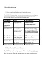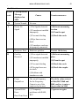
1
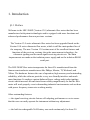
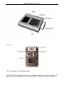
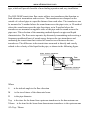
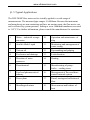
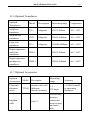
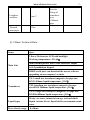
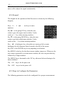
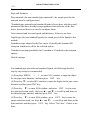
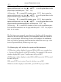
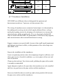
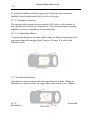
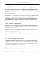
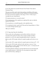
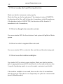
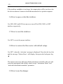
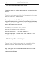
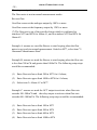
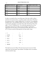
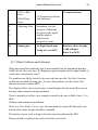
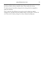
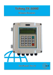
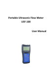
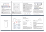
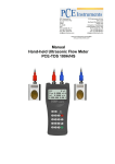
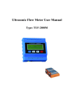
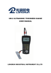
LRF-2000P Portable Ultrasonic Flow Meter User Manual LONGRUN INDUSTRIAL INSTRUMENT CO.,LTD www.ultrasonicscn.com -2- Content 1. Introduction...................................................................................................................................1 §1.1 Preface ..............................................................................................................................1 §1.2 Features: ............................................................................................................................2 §1.3 Outside View.....................................................................................................................2 §1.4 Principle of Measurement..................................................................................................3 §1.5 Typical Applications .........................................................................................................5 §1.6 Optional Transducers ........................................................................................................6 §1.7 Optional Accessories .........................................................................................................6 §1.8 Basic Technical Data: ........................................................................................................7 2. Starting Measurement ...................................................................................................................9 §2.1 Open and Check ................................................................................................................9 §2.2 Built-in Battery..................................................................................................................9 §2.3 Power on ......................................................................................................................... 10 §2.4 Keypad ............................................................................................................................ 11 §2.5 Steps to Configure the Parameters ................................................................................... 11 §2.6 Transducers Mounting Allocation ................................................................................... 14 §2.7 Transducers Installation .................................................................................................. 15 §2.8 Installation Checkup ........................................................................................................ 17 3. How To ....................................................................................................................................... 20 3.1 How to judge if the instrument works properly ................................................................. 20 3.2 How to judge the liquid flowing direction ......................................................................... 21 3.3 How to change between units systems............................................................................... 21 3.4 How to select a required flow rate unit .............................................................................. 21 3.5 How to use the totalizer multiplier .................................................................................... 21 3.6 How to open or shut the totalizers ..................................................................................... 22 3.7 How to reset the totalizers ................................................................................................. 22 www.ultrasonicscn.com -3- 3.8 How to restore the flow meter with default setups ............................................................. 22 3.9 How to use the damper ...................................................................................................... 22 3.10 How to use the zero-cutoff function ................................................................................ 23 3.11 How to setup a zero point ................................................................................................ 23 3.12 How to get a scale factor for calibration .......................................................................... 24 3.13 How to use the system locker .......................................................................................... 24 3.14 How to use 4-20mA current loop output ......................................................................... 24 3.15 How to use the Frequency Output ................................................................................... 26 3.16 How to use the Totalizer Pulse Output ............................................................................ 27 3.17 How to produce an alarm signal ...................................................................................... 27 3.18 How to use the built-in Buzzer ........................................................................................ 29 3.19 How to use the OCT output ............................................................................................. 29 3.20 How to modify the built-in calendar ................................................................................ 29 3.21 How to view the Date Totalizers ..................................................................................... 30 3.22 How to use the Working Timer ....................................................................................... 30 3.23 How to use the manual totalizer ...................................................................................... 30 3.24 How to know how long the battery will last .................................................................... 30 3.25 How to check the ESN and other minor details ............................................................... 30 3.26 How to use the data logger for scheduled output ............................................................. 31 3.27 How to output analogue voltage signal ............................................................................ 31 3.28 How to adjust the LCD display ....................................................................................... 31 3.29 How to use RS232/RS485? ............................................................................................. 32 3.30 How to use automatic amending function for offline compensation ................................ 32 3.31 How to use batch controller ............................................................................................. 32 3.32 How to adjust the analogue output .................................................................................. 32 3.33 How to solidify the parameters ........................................................................................ 33 3.34 How to enter the parameters of user-type-transducer ....................................................... 33 3.35 How to use the circular display function ......................................................................... 34 3.36 How to enter into the linearity correcting? How to enter into the data? ........................... 34 www.ultrasonicscn.com -4- 3.37 How to save / restore frequently-used pipe parameters .................................................... 36 4. Menu Window Details ................................................................................................................ 37 §4.1 Menu Windows Arrangement ......................................................................................... 37 §4.1 Menu Window Details..................................................................................................... 37 5.Troubleshooting ........................................................................................................................... 47 §5.1 Power-on Error Displays and Counter-Measures ............................................................. 47 §5.2 Error Code and Counter-Measures .................................................................................. 47 §5.3 Other Problems and Solutions ......................................................................................... 49 1. Introduction §1.1 Preface Welcome to the LRF-2000P (Version 13.0) ultrasonic flow meter that has been manufactured with patent technologies and is equipped with more functions and advanced performance than our previous versions. The Version 13.0 series ultrasonic flow meter has been upgraded based on the Version 10.0 series ultrasonic flow meter, which is still the main product line of the company. The new Version 13.0 retains most of the excellent features and functions of the previous versions: the pulse measurement technology, the ultrasonic igniting and the small signal receiving circuits etc. The main improvements are made on the isolation power supply and on the isolation RS485 serial port. The LRF-2000P flow meter incorporates the latest ICs manufactured from the famous semiconductor manufacturers like Philips, Maxim, TI, Winbond, and Xilinx. The hardware features the ease of operation, high accuracy and outstanding reliability, while the software provides a very user friendly interface and much more functions. It employs a patent balanced lower voltage multi-pulse igniting circuit which increases the anti-interference ability magnificently so that the flow meter will work properly even in demanding industrial environments such as those with power frequency transverter working nearby. Other outstanding features: ----the signal receiving circuits feature self-adapting performance so as to ensure that the user can easily operate the instrument without any adjustment. ----the built-in rechargeable Ni-H battery can work continuously for about 20 www.ultrasonicscn.com -2- hours without recharging. The advanced circuit design, the integration of the latest semiconductors, the user-friendly software interface both in English and Chinese languages, all these features combine to make the LRF-2000P ultrasonic flow meter the best and the biggest seller on the Chinese market. Moreover, it is gaining more and more recognition on the international flow meter market. §1.2 Features: High accuracy: Linearity: 0.5%, repeatability:0.2%, accuracy up to ±1%. Non-contacting measuring: The ultrasonic flow meter will be adsorbed on the outside of pipe, and then finish the measuring. Non-intrusive, clamp-on transducer, no pressure drop, no pipe disturbance. Wide measuring range: Several types transducer for selection, pipe size from DN15mm to DN6000mm Chinese & English menu: Chinese & English display, easy to operate. Large capacity battery: Built-in rechargeable Ni-MH rechargeable battery, provide over 20 hours of continuous operation. Built-in printer: Built-in mini thermal printer with instant and timing print function, also you can print more than 20 kinds of measuring results if you set in advance. Built-in data logger: Uplink over 20 measuring data to computer or internet. §1.3 Outside View Front View www.ultrasonicscn.com -3- Left view: §1.4 Principle of Measurement The LRF-2000P ultrasonic flow meter is designed to measure the fluid velocity of liquid within a closed conduit. The transducers are a non-contacting, clamp-on www.ultrasonicscn.com -4- type, which will provide benefits of non-fouling operation and easy installation. The LRF-2000P transit time flow meter utilizes two transducers that function as both ultrasonic transmitters and receivers. The transducers are clamped on the outside of a closed pipe at a specific distance from each other. The transducers can be mounted in V-method where the sound transverses the pipe twice, or W-method where the sound transverses the pipe four times, or in Z-method where the transducers are mounted on opposite sides of the pipe and the sound crosses the pipe once. This selection of the mounting method depends on pipe and liquid characteristics. The flow meter operates by alternately transmitting and receiving a frequency modulated burst of sound energy between the two transducers and measuring the transit time that it takes for sound to travel between the two transducers. The difference in the transit time measured is directly and exactly related to the velocity of the liquid in the pipe, as shown in the following figure. Down stream transducer flow V MD T sin 2 Tup Tdown Tdown Tup θ spacing Upstream transducer Where θ is the include angle to the flow direction M is the travel times of the ultrasonic beam D is the pipe diameter Tup is the time for the beam from upstream transducer to the downstream one Tdown is the time for the beam from downstream transducer to the upstream one ΔT=Tup –Tdown www.ultrasonicscn.com -5- §1.5 Typical Applications The LRF-2000P flow meter can be virtually applied to a wide range of measurements. The measured pipe ranges 15-6000mm. Because the instrument and transducers are non-contacting and have no moving parts; the flow meter can not be affected by system pressure, fouling or wear. Standard transducers are rated to 110 ºC. For further information, please consult the manufacturer for assistance. 1. Water、industrial sewage、 10. sea water Operation and maintenance of ship 2. Acid & Alkali Liquid 11. Monitoring and management of water saving 3. Various oil 12. Papermaking and pulping 4. Feed water and drainage 13. Leak detection 5. Detection of water resources 14. Heating 6. Petrochemical 15. Manufacturing of pump、 boiler、cooling tower 7. Food and pharmaceutical industry 16. Management of flow and heat、 control network system 8. Power plant 17. Patrol, tracing and collection of flow 9. Metallurgical mines 18. Measurement and balance of heat www.ultrasonicscn.com -6- §1.6 Optional Transducers Optional Transducers Model Description Measuring range Temperature Small size transducer TS-1 Magnetic DN15-100mm -40~110℃ Medium size transducer TM-1 Magnetic DN50-1000mm -40~110℃ Large size transducer TL-1 Magnetic DN300-6000mm -40~110℃ High-temperature small size transducer THS-1 DN15-100mm -40~160℃ High-temperature medium size transducer THM-1 DN50-1000mm -40~160℃ §1.7 Optional Accessories Optional Accessories Model Description Measuring range Accuracy Ultrasonic thickness meter TT100 measure tube wall thickness, increase accuracy 1.2~ 225.0mm ±1%H±0.1mm(H is measuring thickness) 10m×2 Suit for long distance connection between pipe and main unit lengthen cable www.ultrasonicscn.com Lengthen stretcher Thermal print paper 6m×2 -7- Suit for fixing of transducer over 1000mm pipe 30m §1.8 Basic Technical Data: Items Spec 2 line x 20 character LCD with backlight Working temperature: -20--60℃ Main Unit Mini thermal printer with 24 line character output 4x4+2 pushbutton keypad RS485 serial port, can download the newest software upgrading on our company‟s website TS-1: small size transducer (magnetic) for pipe size: DN15-100mm, liquid temperature ≤110℃ Transducers TM-1:medium size transducer (magnetic) for pipe size:DN50-1000mm, liquid temperature ≤110℃ TL-1: Large size transducer (magnetic) for pipe size: DN300-6000mm, liquid temperature ≤110℃ Liquid types Water, sea water, industrial sewage, acid and alkali liquid, various oils etc. liquid which can transmit sound wave. Flow velocity range 0-±30m/s www.ultrasonicscn.com Accuracy Better than ±1% Power Supply Built-in rechargeable Ni-MH battery (for 20 hours operation) or -8- AC 220V Power Consumption 1.5W Charging Intelligent charging with AC 220V. After charging sufficiently, it automatically stop and display green light Weight Net weight: 2.5kg (main unit) Remarks With a high strength carrying case suitable for normal and harsh environment 2. Starting Measurement §2.1 Open and Check Please check whether the spare parts are according with packing list before installation. §2.2 Built-in Battery The instrument can operate with the built-in Ni-MH chargeable battery, which will last about 20 hours of continuous operation when fully recharged. The charging uses intelligent charging method; users can insert one end of the supply line into the AC220 port, and the other end into power socket, then the charging is finished. When it connected, the red indicator light “CHARGE” on the keyboard flashes, shows that it is charging, when the red light is changed into green, it means charging is finished. The back-up battery uses CR2032 button battery. Its functions are: first, to keep the data not miss; second, to keep the running of real- time clock. If there is no battery, when the external power supply is cut, the real-time clock will not run, and the data of time accumulation will lost. Even though the external supply is cut, the reserve battery can keep the data and clock running for about 100 thousand hours. The voltage of back-up battery is 3V. When the battery is depleted, users can change it by themselves. www.ultrasonicscn.com - 10 - §2.3 Power on Press the ON key to switch on the instrument and press the OFF to turn off the power. Once the flow meter is switched on, it will run a self diagnostic program, checking first the hardware and then the software integrity. If there is any abnormality, corresponding error messages will display. Generally, there should be no display of error messages, and the flow meter will go to the most commonly used Menu Window Number 01 (short for M01) to display the Velocity, Flow Rate, Positive Totalizer, Signal Strength and Signal Quality, based on the pipe parameters configured last time by the user or by the initial program. The flow measurement program always operates in the background of the user interface. This means the flow measurement will keep on running regardless of any user menu window browsing or viewing. Only when the user enters new pipe parameters will the flow meter change measurement to the new parameter changes. When new pipe parameters have been entered or when the power has been just switched on, the flow meter will enter an adjusting mode to make the signals magnified with proper amplification. By this step, the flow meter is going to find the best threshold of receiving signal. The user will see the progress by the number 1, 2, or 3, which are indicated on the right lower corner of the LCD display. Any user-entered configuration value will be retained into the NVRAM of the flow meter, until it is modified by the user. www.ultrasonicscn.com - 11 When the transducers have been adjusted on the pipe by the user, the flow meter will re-adjust the signal automatically. §2.4 Keypad The keypad for the operation of the flow meter is shown by the following diagram, Keys 0 ~ 9 and . are keys to enter numbers. Key ▲/+ is the going UP key, when the user wants to go to the upper menu window. It also works as „+„ key when entering numbers. Key ▼/- is the going DOWN key, when the user wants to go down-sided menu window. It also works as the „–„ key when entering numbers. Key ◄ is backspace key, when the user wants go left or wants backspace the left character that is located to the left of the cursor. Key ENT is the ENTER key for any inputting or selections. Key MENU is the key for the direct menu window jump over. Whenever the user wants to proceed to a certain menu window, the user can press this key followed by 2-digit numbers. The MENU key is shortened as the „M‟ key afterward when referring to the menu windows. The ON key is for the power on. The OFF key is for the power off. §2.5 Steps to Configure the Parameters The following parameters need to be configured for a proper measurement: www.ultrasonicscn.com - 12 Pipe outer diameter Pipe wall thickness Pipe materials (for non-standard pipe materials*, the sound speed for the material must be configured too) *Standard pipe materials and standard liquids refer to those with the sound parameters that have already been programmed into software of the flow meter, therefore there is no need to configure them Liner material and its sound speed and thickness, if there is any liner. Liquid type (for non-standard liquids, the sound speed of the liquid is also needed) Transducer type adapted to the flow meter. Generally the Standard M1 clamp-on transducers will be the selected option. Transducer mounting methods (the V-method or Z-method is the common option) Default settings For standard pipe materials and standard liquids, the following detailed step-by-step setup is recommended. (1) Press keys MENU 1 1 to enter M11 window to input the digits for the pipe outer diameter, and then press ENT key. (2) Press key ▼/- to enter M12 window to input the digits for the pipe outer diameter and then press ENT key. (3) Press key ▼/- to enter M14 window, and press ENT key to enter the option selection mode. Use keys ▲/+ and ▼/- to scroll up and down to the intended pipe material, and then press ENT key. (4) Press key ▼/- to enter M16 window, press ENT key to enter the option selection mode, use keys ▲/+ and ▼/- to scroll up and down to the liner material, and then press ENT key. Select “No Liner”, if there is no liner. www.ultrasonicscn.com - 13 (5) Press key ▼/- to enter M20 window, press ENT key to enter the option selection mode, use keys ▲/+ and ▼/- to scroll up and down to the proper liquid, and then press ENT key. (6) Press key ▼/- to enter M23 window, press ENT key to enter the option selection mode, use keys ▲/+ and ▼/- to scroll up and down to the proper transducer type, and then press ENT key. (7) Press key ▼/- to enter M24 window, press ENT key to enter the option selection mode, use keys ▲/+ and ▼/- to scroll up and down to the proper transducer mounting method, and then press ENT key. (8) Press key ▼/- to enter M25 window to check up the installation space then install the transducers on the pipe, and then press ENT key to go to M01 for the results. The first-time users may need some time to get familiar with the operation. However, the user friendly interface of the instrument makes the operation quite easy and simple. Before long, the user will configure the instrument with very little key pressing, since the interface allows the user to go to the desired operation directly without any extra steps. The following tips will facilitate the operation of this instrument. (1) When the window display is between M00 to M09, press a number key x , the user will go directly to the M0x window. For example, if the current window displays M01, press 7 and the user will go to M07. (2) When the window display is under M00 to M09, press the ENT key and the user will go to M90; press ENT key to return. Press the dot key to go to M11 When the window display is under M25, press ENT key to go to M01. www.ultrasonicscn.com - 14 - §2.6 Transducers Mounting Allocation The first step in the installation process is the selection of an optimum location in order to obtain a more accurate measurement. For this to be completed effectively, a basic knowledge about the piping and its plumbing system would be advisable. Principles to selection of an optimum location: ⑴ Choose the straight pipe section full of liquid, e.g. the vertical segment of the pipe or the horizontal segment which is full of liquid. ⑵ Make sure that the temperature on the location does not exceed the range for the transducers. ⑶ Take the pipes fouling into consideration. Select a straight length of a pipe with no fouling, if the condition is not satisfying; consider the fouling thickness as part of the liner for a better result. ⑷ Select the pipe whose material is homogeneous, compact, and easy to transmit ultrasonic wave. Steps to the installation of the transducers: ⑴ Locate an optimum position where the straight pipe length is sufficient, and where pipes are in a favorable condition, e.g. newer pipes with no rust and easy to operate. ⑵ Clean any dust and rust. For a better result, polishing the pipe with a sander is strongly recommended. ⑶ Apply adequate coupler to the spot where the transducers are to be installed and leave no space between the pipe surface and the transducers. Note: ⑴ Extra care should be taken to avoid any sand or dust particles left between the pipe outer surface and the transducers. L up L dn 20D 5D www.ultrasonicscn.com - 15 L up L dn 20Dpipe, the transducers 5D ⑵ To avoid gas bubbles inside the upper part of the should be installed horizontally by the side of the pipe. L up L dn The following table shows examples of optimum30D locations: 5D §2.7 Transducers Installation LRF-2000P uses different colors to distinguish the upstream and downstream transducers. Upstream: red; downstream: blue. The wiring of transducers uses customized twisted pair, it is determined by the sending and receiving circuits which employ balanced lower voltage multi-pulse igniting circuit, the advantage of twisted pair is to increase the anti-interference ability magnificently. If we use the single-shielded HF cable or double-shielded cable, the performance of flow meter may degrade, and can not measure when external interference is strong. Suggest customers use special cable, because it has small signal impairment and high anti-interference ability, so that guarantees flow meter long-term and reliable work. Steps to the installation of the transducers Locate an optimum position where the straight pipe length is sufficient, and where pipes are in a favorable condition, e.g., newer pipes with no rust and ease of operation. Clean any dust and rust. For a better result, polishing the pipe with a sander is strongly recommended. Apply adequate coupler to the spot where the transducers are to be installed and leave no gap between the pipe surface and the transducers. Extra care should be taken to avoid any sand or dust particles left between the pipe outer surface and the transducers. www.ultrasonicscn.com - 16 To avoid gas bubbles inside the upper part of the pipe, the transducers should be installed horizontally by the side of the pipe. §2.7.1 Transducers Spacing The spacing value shown on menu window M25 refers to the distance of inner spacing between the two transducers. The actual transducers spacing should be as close as possible to the spacing value. §2.7.2 V-method Installation V-method installation is the most widely mode for daily measurement with pipe inner diameters ranging from 20 mm to 300 mm. It is also called reflective mode. 2.7.3 Z-method Installation Z-method is commonly used when the pipe diameter is from 100mm to 6000mm, as a matter of fact, we suggest that you can use it over 200mm §2.7.4 Installation W-method www.ultrasonicscn.com - 17 W-method is usually used on plastic pipes with a diameter from 10mm to 100mm. §2.7.5 Installation N-method Rarely used method. §2.8 Installation Checkup Through the checkup of the installation, one can: check the receiving signal strength, the signal quality Q value, the traveling time difference of the signals, the estimated liquid speed, the measured traveling time of the signals and the calculated traveling time ratio. Therefore, optimum measurement result and longer running time of the instrument can be achieved. §2.8.1 Signal Strength Signal strength indicates the amplitude of receiving ultrasonic signals by a 3-digit number. [00.0] means there is no signal detected and [99.9] refers to the maximum signal strength that can be received. Although the instrument works well if the signal strength ranges from 50.0 to 99.9, stronger signal strength should be pursued, because a stronger signal means a better result. The following methods are recommended to obtain stronger signals: (1) Relocate a more favorable location, if the current location is not good enough for a stable and reliable flow reading, or if the signal strength is lower than 70.0. www.ultrasonicscn.com - 18 (2) Try to polish the outer surface of the pipe, and apply more coupler to increase the signal strength. (3) Adjust the transducers both vertically and horizontally while checking the varying signal strength, stop at the highest position, and then check the transducers spacing to make sure the transducers spacing is the same as what the M25 shows. §2.8.2 Signal Quality Signal quality is indicated as the Q value in the instrument. A higher Q value would mean a higher Signal and Noise Ratio (short for SNR), and accordingly a higher degree of accuracy would be achieved. Under normal pipe condition, the Q value is in the range 60.0-90.0, the higher the better. Causes for a lower Q value could be: Interference of other instruments and devices such as a powerful transverter working nearby. Try to relocate the flow meter to a new place where the interference can be reduced. Bad sonic coupling for the transducers with the pipe. Try to apply more coupler or clean the surface, etc. Pipes are difficult to be measured. Relocation is recommended. §2.8.3 Total Transit Time and Delta Time The numbers displayed on menu window M93 are called total transit time and delta time respectively. They are the primitive data for the instrument to calculate the flow rate inside the pipe. So the flow rate indication will vary accordingly with the total time and delta time. The total transit time should remain stable or vary little. If the delta time fluctuates more than ±20%, it means there are certain kinds www.ultrasonicscn.com - 19 of problems with the transducer installation. §2.8.4 Time Ratio between the Measured Total Transit Time and the Calculated Time This ratio would be used to check the transducer installation. If the pipe parameters are entered correctly and the transducers are installed properly, the value for this ratio should be in the range of 100±3. If this range is exceeded, the user should check: If the pipe parameters are correctly entered. If the actual spacing of the transducers is right and the same as what the window M25 shows. If the transducers are installed properly in the right directions. If the mounting location is good and if the pipe has changed shape or if there is too much fouling inside the pipes Other poor condition. §2.8.5 Inspection Item after Installation Check out the tube wall parameter and confirm whether each item is corrected, take record of the flow meter sequence number and other parameter, as well as the signal strength together kept for inspection; Check out the M 90, judge whether the signal strength and Q value is over 70; Check out the M 91, judge whether the signal transit ratio between 97---103 Check out the M 60, judge whether the date and time is correct. If not, please adjust it to correct, otherwise date function, power –on and power-off function cannot work regularly For fixed application situation, pressing M26 the first item can backup the current input parameter, which make sure the parameter storage when powered off or battery running out. www.ultrasonicscn.com - 20 - 3. How To 3.1 How to judge if the instrument works properly Enter into M08, if „R‟ is displayed on the screen, the instrument is working properly, If 'E' is displayed, the current loop output is over-ranged. Increasing the range setting in M57 will make the 'E' letter disappear. If you do not use current loop output, you may ignore this error. If 'Q' is displayed, the frequency output is over-ranged. Increasing the range setting in M69 will make the 'Q' letter disappear. If you do not use frequency output, you may ignore this error. If an „H‟ flashes on that place, there could be poor signal received. Please refer to the chapters on diagnosis. If 'G' is displayed, the flow meter is adjusting system gain. This is normal as far as it does not last long time. If an „I‟ is displayed, it means that there is no signal detected. If 'J' is displayed, there is hardware problem. Turn off the power, then, turn on the power again. If the problem remains, refer to Chapter 5 for diagnosis details. www.ultrasonicscn.com - 21 - 3.2 How to judge the liquid flowing direction Make sure that the instrument works properly Check the flow rate for the indication. If the displayed value is POSITIVE, the direction of the flow will be from the A transducers to the B transducers; if the displayed value is NEGATIVE, the direction will be from the B transducers to the A transducers; 3.3 How to change between units systems Use menu window M30 for the selection of unit system in English or Metric system. 3.4 How to select a required flow rate unit Use menu window M31 to select the flow unit first and then the timing unit. 3.5 How to use the totalizer multiplier Use window M33 to select a proper totalizer. Make sure that the totalizer pulse is appropriately speeded. It should not be too fast and neither too slow. A speed of producing a pulse in several seconds or minutes is preferable. If the totalizer multiplier is too small, there can be a loss of accumulation pulse because the output device can output only one pulse in a measurement period (500milliseconds) www.ultrasonicscn.com - 22 If the totalizer multiplier is too large, the output pulse will be too fewer for the devices that are connected with the instrument for a quicker response. 3.6 How to open or shut the totalizers Use M34, M35 and M36 to turn on or turn off the POS, NEG, or NET totalizer respectively. 3.7 How to reset the totalizers Use M37 to reset the proper totalizer. 3.8 How to restore the flow meter with default setups Use M37, when the „selection‟ message is displayed. Press the dot key first and the message „Master Erase‟ will display, then press the backspace key ◄ The master erase step will erase all the parameters entered by the user and setup the instrument with default values except “instrument factor” and “network identification number” parameter 3.9 How to use the damper www.ultrasonicscn.com - 23 The damper acts as a filter for a stable reading. If „0‟ is entered in window M40, that means there is no damping. A bigger number brings a more stable effect. But bigger damper numbers will prevent the instrument from acting quickly. Numbers 0 to 30 are commonly used for the damper value. Default value is 10 seconds. 3.10 How to use the zero-cutoff function The number displayed in window M41 is called the lower flow rate cut-off value. The flow meter will replace these flow rate values that are absolutely less than the low-cutoff value with „0‟. This means the flow meter will avoid any invalid accumulation when the actual flow is below the zero-cutoff value. Generally the default value is 0.03m/s The low-cutoff value does not affect the flow measurement when the actual flow is absolutely greater than the low-cutoff value. 3.11 How to setup a zero point There exists a „Zero Point‟ with certain installation which means the flow meter will display a non-zero value when the flow is absolutely stopped. In this case, setting a zero point with the function in window M42 will bring a more accurate measurement result. Make sure that there is no liquid running inside the pipe, and then run the function in window M42 by pressing the ENT key. www.ultrasonicscn.com - 24 - 3.12 How to get a scale factor for calibration A scale factor is the ratio between the „actual flow rate‟ and the indicated value by the flow meter. It can be determined by calibration with standard flow calibration equipment. You may change the scale factor in menu window M45. The scale factor can be determined by calibration with flow calibration equipment. 3.13 How to use the system locker The system locker provides a means of preventing inadvertent configuration changes or totalizer resets. When the system is locked, menu window browsing can be done without affecting any change, but any modifications are prohibited. The system can be locked without a password or with a 1 to 4 digit password. With a no-password locking, directly press the ENT key in M47 If the password is forgotten, please contact the factory. 3.14 How to use 4-20mA current loop output The accuracy of the current loop output is better than 0.1%. It can be configured to different mode, such as 4-20mA mode, 0-20mA etc. Mode selection can be made in menu M55. Refer to the next chapter for details on www.ultrasonicscn.com - 25 M55. In order to use the 4-20mA output function, you need not only select the mode to be 4-20mA in M55, but also set the flow rate values which correspond to the minimum current (4mA) and the maximum current (20mA). Enter the two values in M56 and M57. Example A: flow rate range is 0-500m3/h. Just enter 0 in M56 and 500 in M57. Example B: flow rate range is -500-0-1000m3/h. If flow direction is not an issue for you, you may select 20-4-20mA mode in M55. Then, enter 500 in M56 and 1000 in M57. If flow direction is an issue, you may select 0-4-20mA mode in M55. This means that the current loop will output 0-4mA when flow rate is negative and 4-20mA when flow rate is positive. Enter -500 in M56 and 1000 in M57. You may need to calibrate and test the current loop output before using it. Just go to menu M58 and do the following: First, connect an ammeter to the current loop output. Press MENU 5 8 , then ENT to enter into menu M58. Use ▲/+ and ▼/- to display "0mA", "4mA", "8mA", "16mA", "20mA" orderly, record the corresponding reading on the ammeter. Calculate the differences between the readings and the selected ones. For instance, when 4mA is selected, the actual output current shown on the ammeter is 4.01mA. Then, the difference is 0.01mA. www.ultrasonicscn.com - 26 If the differences are not within tolerance, calibrate the current loop The present current loop output is displayed in Window M59. It changes along with flow rate change. 3.15 How to use the Frequency Output There is a Frequency Output in all LRF-2000 series flow meters. This frequency output signal, which represents the flow rate, is intended to connect with other instruments. The Frequency Output is totally user-configurable. Generally, four parameters should be configured for the setups. Enter the lower flow rate value in window M68 and the higher flow rate value in window M69. Enter the frequency range in window M67. For example, assume that the flow rate varies in a range 0m3/h to 3000m3/h, and an output signal is at a maximum frequency of 1000Hz, the minimum of 200Hz is going to be required for other instrumentation. The user should enter 0 in M68 and 3000 in M69, and enter 200 and 1000 in window M67. Please note that the user has to make the selection with OCT setups in window M78. www.ultrasonicscn.com - 27 - 3.16 How to use the Totalizer Pulse Output The totalizer output will produce a pulse output with every unit flow of the totalizer. The totalizer pulse output can only be realized by mapping the pulse output to the OCT or BUZZER hardware devices. For example, assume that the POS totalizer pulse output is needed, and every pulse should represent 0.1cubic meter of liquid flow; the pulse output will be mapped to the internal Buzzer, so that with every 0.1 cubic meter of flow the BUZZER will beep for a while. The following setups should be taken / performed: Select the unit Cubic Meter under window M32. Select the Multiplier as „2. X0.1‟ under window M33. Select the output option „9. POS INT Pulse‟ under window M77. (INT stands for totalized ) 3.17 How to produce an alarm signal There are 2 types of hardware alarm signals that are available with this instrument. One is the Buzzer, and the other is the OCT output. Both for the Buzzer and OCT output the triggering sources of the event include the following: There is no receiving signal www.ultrasonicscn.com - 28 There is poor signal received. The flow meter is not in normal measurement modes. Reverse flow. Overflow occurs at the analogue output by 100% or more Overflow occurs at the frequency output by 120% or more. (7) The flow rate is out of the specified range which is configured in windows M73 and M74 for Alarm #1, and in windows M75 and M76 for Alarm #2. Example A: assume we need the Buzzer to start beeping when the flow meter is not ready in normal measurement. Switch to M77, select item "2. Abnormal Measurement State" Example B: assume we need the Buzzer to start beeping when the flow rate is less than 300 m3/h and greater than 1000m3/h. The following setup steps would be recommended: (1) Enter flow rate lower limit 300 in M73 for #1 alarm, (2) Enter flow rate upper limit 1000 in M74 for #1 alarm, (3) Select item '6. Alarm #1' in M77. Example C: assume we need the OCT output to activate when flow rate exceeds 100~500m3/h and the relay output to activate when flow rate exceeds 600~1000m3/h. The following setup steps would be recommended: (1) Enter flow rate lower limit 100 in M73 (2) Enter flow rate upper limit 500 in M74 (3) Enter flow rate lower limit 600 in M75 (4) Enter flow rate lower limit 1000 in M76 www.ultrasonicscn.com - 29 (5) Select item '6. Alarm #1' in M78 (6) Select item '6. Alarm #1' in M79. 3.18 How to use the built-in Buzzer The built-in buzzer is user-configurable. It can be used as an alarm. Use M77 for setups. 3.19 How to use the OCT output The OCT output is user-configurable, which can be performed by selecting the proper input source such as pulse output. Use M78 for the setups. Please make sure that the Frequency Output shares the OCT. The OCT output shares pins with the RS-232C interface, and the terminal is at Pin 1 and 8 3.20 How to modify the built-in calendar No modification on the built-in calendar will be needed in most cases. The calendar runs on insignificant amount of power supply. Modification will be required only in such cases as when the battery is totally consumed, or when the changing of the battery takes a long time. Press the ENT key under M60 for Modification. Use the dot key to skip over these digits that need no modification. www.ultrasonicscn.com - 30 - 3.21 How to view the Date Totalizers Use M82 to view the date totalizers that are comprised of a daily totalizer, a monthly totalizer and a yearly totalizer. 3.22 How to use the Working Timer Use the working timer to check the time that has passed with a certain kind of operation. For example, use it as a timer to show how long a fully-charged battery will last. Under M72, press ENT key and then select YES to reset the timer. 3.23 How to use the manual totalizer Use M38 for the manual totalizer. Press ENT key to start and stop the totalizer. 3.24 How to know how long the battery will last Use M07 to check how long the battery will last. Also please refer to §.2.1 3.25 How to check the ESN and other minor details Every set of the LRF-2000S flow meter utilizes a unique ESN to identify the www.ultrasonicscn.com - 31 meter. The ESN is an 8-digit number that provides the information of version and manufacturing date. The user can also employ the ESN for instrumentation management. The ESN is displayed in window M61. Other details about the instrument are the total working hours displayed in window M+1, and the total power-on times displayed in window M+4. 3.26 How to use the data logger for scheduled output Use menu window 51 to setup the time of scheduled output, including start time, time interval and how many times of output. Then use menu window 50 to turn on data logger and select the items you want to output. 3.27 How to output analogue voltage signal Parallel a 250 resistance to the terminal of the Current loop output (No.21, 22), then you can change the 4-20mA output to analogue voltage output. 3.28 How to adjust the LCD display You may use menu window 70 to setup the LCD display backlight and menu window 71to adjust contrast it. www.ultrasonicscn.com - 32 - 3.29 How to use RS232/RS485? Use menu window 62 to set up RS232/RS485. All the devices connected with flow meter should have matched serial configuration. The following parameters can be configured: Baud rate (300 to 19200 bps), parity, data bits (always is 8), stop bits (1). 3.30 How to use automatic amending function for offline compensation Use menu window 83 turn on or turn off this function. When the function is enabled, the flow meter will estimate the average flow uncounted (or „lost‟) during the offline session and add the result to the totalizer. This function is not recommended. The user should manage to avoid the offline time to keep precision of the measurement result. 3.31 How to use batch controller Please do the following to use the batch controller: 1) Go to menu window 80 to select the trig signal. 2) Go to menu window 78 (OCT output) or 79 (relay output), select “8 Batch Control”. 3) Use menu window 81 to set the flow batch value (dose). 3.32 How to adjust the analogue output www.ultrasonicscn.com - 33 We have adjusted every set of meter before delivery. Unless you find the current indicated in menu 58 is different with the actual current output, please do not do this operation. Press keys MENU ▼/- 0 , use the password ”4213068” to enter the window. Notice: the window will close after power off and the password will become invalid then. Press keys MENU ▼/- 1 , to adjust the 4mA current output: use precision ammeter to measure the output current, at the same time, use ▲/+ ▼/- to adjust the digital on the flow meter until the ammeter indicate 4.00. Then press ENT to enter the window of adjusting the 20mA output. When finished adjusting, you have to use menu window 26 to store the result into the flash memory, so that it will be solidified and will not be lost even the reserve battery removed. 3.33 How to solidify the parameters There are three kinds of parameters for the new generation LRF/TUC-2000: 1) Current parameters, the parameters are stored in the RAM. They will be lost when one cut the power or remove the reserve battery. 2) Solidified parameters, you may use menu window 26 to store the parameters in the Flash memory and they will not be lost even power off. This menu window is also a switch for the parameters in flash memory to be loaded when power is turned on. The default option is that the parameters will be loaded. So if the parameters are very stable, you may need this option. 3) User frequently-used parameters, you can use menu window 27 to store or restore from the internal Flash memory, as many as 9 different pipe parameter configurations. 3.34 How to enter the parameters of user-type-transducer If a user-type-transducer is selected in menu window 23, you need proceed www.ultrasonicscn.com - 34 to enter additional 4 user-type-wedge parameters that describe the user transducers. If the PI-type transducer is selected, you need enter additional 4 PI-type transducer parameters that describe the PI-type transducers. 3.35 How to use the circular display function When entering menu window 95, the circular display function will be started automatically. The following windows will be displayed one by one, each window will stay for 8 seconds: M95>>M00>>M01>>M02>>M02>> M03>>M04>>M05>>M06>>M07>>M08>>M90>>M91>>M92>> M93>> M94>>M95. This function allows the user to visit all the important information without any manual action. To stop this function, simply press a key. Or switch to a window other than M95. 3.36 How to enter into the linearity correcting? How to enter into the data? When the product leaved the factory, the function is closed. The menu can realize almost 12 parts linearity correcting. The user can choose from two points to twelve points to execute the linearity correcting according to user actual condition. In order to explain the usage method of the menu, we suppose that we get the following table data through calibration the meter. Reference standard Instrumented show Correction coefficient www.ultrasonicscn.com - 35 equipment flow (m3/h) flow (m3/h) (standard / show value) 1.02 0.0998 1.02 5.11 5.505 0.93 10.34 10.85 0.95 20.45 19.78 1.03 50.56 51.23 0.99 In order to revised the flow exceed the scope of the above table, without mutations of correction factor, we add two points on the basis of the above five points, (0 m3/h, 1.0) and (100000 m3/h, 1.0). (0 m3/h, 1.0) is called the minimum flow of the amendment point, this set of data is used to facilitate to generated a appropriate correction factor when Instrumented show flow under 1.02 m3/h. (100000 m3/h, 1.0) is called the maximum flow of the amendment point, this set of data is used to facilitate to generated a appropriate correction factor when Instrumented show flow above 50.56 m3/h. So that we get the following data sets from small to large. ( 0 , ( 0.0998 , ( 5.505 , 0.93 ) ( 10.85 , 0.95 ) ( 19.78 , 1.03 ) ( 51.23 , 0.99 ) ( 100000 , 1 ) 1.02 ) 1. ) The total is seven sets of data. The next step is to put seven sets of data entered into the Instrument. Pay attention to the input order in accordance with from small to large. www.ultrasonicscn.com - 36 To enter the menu M48, then input the data set number “7”, to be followed in the above seven sets of data, we revised the setup of a multi-segment linearity correcting. If you need to cancel linearity correcting, simply enter “0” in the menu M48. Decommissioned linearity correcting, you just need to enter in the menu M48 data points (in this case, is “7”). Noted: before the calibration of the instrument, you must first close the linearity correcting function. If under the condition that the linearity correcting function has not closed, the calibration data sets arising from the amendment must be dealing with the reverse curve of the data following the original amendment, then input to the Instrument. Reverse amendment is very complicated, and should be avoided. 3.37 How to save / restore frequently-used pipe parameters You can use menu window 27 to store or restore from the internal Flash memory, as many as 9 different pipe parameter configurations. 4. Menu Window Details §4.1 Menu Windows Arrangement M00~M09 windows for the display of the flow rate, velocity, date time, totalizer, battery voltage and estimated working hours for the battery. M10~M29 windows for entering the pipe parameter. M30~M38 windows for flow rate unit selections and totalizer unit selections. M40~M49 windows for response time, zeroing, calibration and modification password setup. M50~M89 windows for the printer output, RS-485 output, OCT output, current output, frequency signal output, sound alarms, and date totalizer.etc M90~M94 are diagnostic windows for a more accurate measurement. M97~M99 are not windows but commands for the outputting of display copying and pipe parameter setups. M+0~M+9 are windows for some additional functions, including a scientific calculator, viewer on records such as total working hours, turn-on and turn-off times, dates and times when the flow meter has been turned on or turned off. There are menu windows which have no functions, or functions were cancelled because they are not applied to this version of the software. §4.1 Menu Window Details Menu window Function No. M00 Display flow rate and net totalizers M01 Display flow rate, velocity M02 Display date time and positive totalizer www.ultrasonicscn.com - 38 M03 Display net flow rate and totalizer M04 Display date and time, flow rate M05 Display total energy and energy rate M06 Display temperatures,T1,T2 M07 Display analog inputs, converted value and current value for AI3,AI4 M08 Display the all the detailed working status M09 Display today‟s total flow M10 Window for entering the outer perimeter of the pipe M11 Window for entering the outer diameter of the pipe 0 to 18000mm is the allowed range of the value M12 Window for entering pipe wall thickness M13 Window for entering the inner diameter of the pipe M14 Window for selecting pipe material Standard pipe materials (that the user need not know the speed ) include: (0) carbon steel iron (4) copper asbestos (1) stainless steel (5) PVC (2) cast iron (3) ductile (6) aluminum (7) (8) fiberglass M15 Window for entering the pipe material speed only for non-standard pipe materials M16 Window for selecting the liner material, select none for pipes without any liner Standard liner materials that the user need not know the speed include: (1) Tar Epoxy (2) Rubber (3) Mortar (4) www.ultrasonicscn.com - 39 Polypropylene (5) Polystryol Polyethylene (6)Polystyrene (9) Ebonite (10) Teflon (7) Polyester (8) M17 Window for entering the liner material speed, only for non-standard liner materials M18 Window for entering the liner thickness, if there is a liner M19 Window for entering the ABS thickness of the inside wall of the pipe M20 Window for selecting fluid type For standard liquids that the user need not know the liquid speed include: (0) Water Gasoline (1) Sea Water (4) Fuel oil (5) Crude Oil Butane at 0C (8)Other liquids Oil (11)Peanut Oil (2) Kerosene (3) (6) Propane at -45C (7) (9) Diesel Oil (10)Caster (12) #90 Gasoline (13) #93 Gasoline (14) Alcohol water at 125C (15) Hot M21 Window for entering the fluid sonic velocity, only for non-standard liquids M22 Window for entering the viscosity of the non-standard liquids M23 Window for selecting the proper transducers There are 20 different types of transducers for selection. If the user-type-transducer is selected, system will prompt anther 4 user-type-wedge parameters to be input. If the π-type transducer is selected, the system needs also another 4π type transducer parameters M24 Window for selecting the transducer mounting methods Four methods can be selected: www.ultrasonicscn.com - 40 (0) V-method (1) Z-method (2) N-method (3) W-method M25 Display the transducer mounting spacing M26 A switch for the parameters in flash memory will be loaded when power is turned on. The default option is that the parameters will be loaded. If this switch is not turned on, the system will try to use the parameters in the system RAM, if these parameters are ok or the system will load the parameters in flash memory. Function to store the current parameters into the flash memory. M27 Entry to store to or restore from the internal Flash memory, as many as 9 different pipe parameter configurations M28 Select YES or NO for the instrument to determine whether or not to hold (or to keep) the last correct value when poor signal condition occurs. YES is the default setup M29 Pipe empty setup. Enter a value ranging from 00 to 99, 0 is the default value. The flow rate will be set to 0 if the signal strength is below the entered value. M30 Window for selecting unit system. Default value is „Metric‟. The change from English to Metric or vice versa will not affect the unit for totalizers. M31 Window for selecting flow rate that will be used by the instrument afterward. Flow rate can be in 0. Cubic meter 1. Liter short for (m3) (L) 2. USA gallon (GAL) 3. Imperial Gallon (IGL) 4. Million USA gallon (MGL) 5. Cubic feet (CF) 6. Oil barrel (OB) 7. Imperial liquid barrel (IB) www.ultrasonicscn.com - 41 The flow unit in terms of time can be per day, per hour, per minute or per second. So there are 32 different flow rate units in total for selection. M32 Window for selecting the totaliziers‟ working unit M33 Select totalizer multiplier The multiplier ranges from 0.001 to 10000 M34 Turn on or turn off the NET totalizer M35 Turn on or turn off the POS totalizer M36 Turn on or turn off the NEG totalizer M37 (1) Totalizer reset (2) Restore the instrument to the default parameters as the manufacturer did by pressing the dot key followed by the backspace key. Take care or make note on the parameters before doing the restoration M38 Press-a-key-to-run or to stop totalizer for easier calibration M39 Interface language selection in Chinese and English. This selection could also be changed automatically by the system, if English LCD display is used as the display device. M3. Setup for local segmental LCD display. Enter 0 or 1 for the non-auto-scan mode; Enter 2~39 for the auto-scan mode, in which mode the display will automatically scan displaying from 00 to the entered number of the local segmental LCD display. M40 Flow rate damper for a stable value. The input range is 0 to 999 seconds. 0 means there is no damping. Default value is 10 seconds M41 Lower flow rate cut-off to avoid invalid accumulation. M42 Zero point setup under the condition when there is no liquid running inside the pipe. www.ultrasonicscn.com - 42 M43 Clear the zero point set by the user, and restore the zero point set by the manufacturer M44 Set up a manual flow bias. Generally this value should be 0. M45 Scale factor for the instrument. The default value is „1‟. Keep this value as „1‟, when no user calibration has been made. M46 Network environment Identification Number. Any integer can be entered except 13(0DH, carriage return), 10 (0AH, line feeding), 42 (2AH), 38, 65535. Every set of the instrument in a network environment should have a unique IDN. Please refer to the chapter for communication. M47 System locker to avoid modification of the parameters by mistake M48 Entry to linearity correct data inputs. There are as many as 12 point-data can be input M49 Displays the input contents for the serial port M50 Switches for the built-in data logger. There are as many as 22 different items can be chosen M51 Time setup for the data logger M52 Data logging direction control. If „Send to RS-485‟ is selected, all the data produced by the data logger will be transmitted out through the RS-232/RS-485 interface If „To the internal serial BUS „ is selected, the data will be transmitted to the internal serial bus which allows a thermal printer,4-20mA analog output module M53 Display the converted value and current value for analog input AI5 M54 Pulse width setup for the OCT(OCT1) output M55 Analog output mode selection. 9 modes to be chosen M56 Setup for the value via 4mA of the analog output M57 Setup for the value via 20mA of the analog output M58 Analog output checkup www.ultrasonicscn.com - 43 M59 Current output form the analog output M60 Calendar. Press ENT for modification. Use the dot key to skip the digits that need no adjusting. M61 Display Version information and Electronic Serial Number (ESN) that are unique for each LRF-2000 series flow meter. The users may employ the ESN for instrumentation management M62 RS-232/RS-485 setup. Baud rate can be 300 to 19200 bps M63 Communication protocol selection. Default is for protocols which have ASCII format, such as MODBUS-ASCII, Meter-BUS, Fuji Extended Protocol.The other select is for MODBUS_RTU M64 AI3 value range inputs, two values which are presented by the 4mA and 20mA current should be input M65 AI4 value range inputs M66 AI5 value range inputs M67 Input the frequency range for the frequency output. The biggest range is 0Hz-9999Hz. Default value is 0-1000 Hz M68 Enter a flow rate value that corresponds to lower frequency M69 Enter a flow Rate value that corresponds to higher frequency M70 LCD display backlight control. The entered value indicates how many seconds the backlight will be on with every key pressing. M71 LCD contrast control. The LCD will become darker or brighter when a value is entered. M72 Working timer. It can be cleared by pressing ENT key, and then select YES. M73 Enter Lower Flow Rate value that will trigger the #1 Alarm. There are two virtual alarms in the system. By “virtual” we mean that the user must redirect the output of the alarms by setup the output hardware in M78 and M77 M74 Enter the higher flow rate value that will trigger the #1 Alarm. www.ultrasonicscn.com - 44 M75 Enter the lower flow rate value that will trigger the #2 Alarm. M76 Enter the higher flow rate value that will trigger the #2 Alarm. M77 Buzzer setup. If a proper input source is selected, the buzzer will beep when the trigger event occurs M78 OCT (Open Collect Transistor Output) setup By selecting a proper input source, the OCT hardware will close when the trigger event occurs M79 Relay or OCT2 setup By selecting a proper input source, the hardware will close when the trigger event occurs Note: in order to make the user interface compatible with the future LRF-2000, the name RELAY was used other than OCT2. But in fact it is an OCT output. M80 Signal selection for the built-in batch controller M81 The built-in batch controller M82 Date totalizer by day, by month and by year M83 Automatic total flow correction switch M84 Energy unit select M85 Temperature select M86 Specific heat select M87 Energy totalizer switch M88 Energy multiplier M89 (1) display the temperature difference. (2) the window to set the lowest temperature difference. M90 Display signal strength, signal quality Q value Signal strength is presented by 00.0 to 99.9, the bigger the value, the bigger the signal strength will be, and more reliable readings www.ultrasonicscn.com - 45 will be made. Q value is presented by 00 to 99, the bigger the better. It should at least be great than 50 for normal operations. M91 Displays the Time Ratio between the Measured Total Transit Time and the Calculated time. If the pipe parameters are entered correctly and the transducers are properly installed, the ratio value should be in the range of 100±3%. Otherwise the entered parameters and the transducer installation should be checked. M92 Displays the estimated fluid sound velocity. If this value has an obvious difference with the actual fluid sound speed, pipe parameters entered and the transducer installation should be checked again. M93 Displays total transit time and delta time(transit time difference) M94 Displays the Reynolds number and the pipe factor used by the flow rate program. M95 Display the positive and negative energy totalizers Entry to start the loop-displaying windows from M00…M08 to M90…M95. The loop-displaying will stop when any key pressed. M96 Command for the thermal printer to advance 5 lines of paper M97 Command to record the pipe parameters entered by the user. The printing data can be directed either to the internal serial bus or to RS-232C serial interface M98 Command to print the diagnostic information. The printing data can be directed either to internal serial bus or to RS-232C serial interface M99 Command to copy the current display. The printing data can be directed either to the internal serial bus or to RS-232C serial interface M+0 Browse the 32 recorded instrument power-on and power-off date and time with the flow rate at the time of power on and off M+1 Displays the total working time of the instrument www.ultrasonicscn.com - 46 M+2 Displays the last power-off date and time M+3 Displays the last power-off flow rate M+4 Displays how many times of instrument has been powered on M+5 A scientific calculator for the convenience of field working. All the values are in single accuracy. M+6 Enter a number as the velocity of the liquid for the system to determine if another kind of liquid is running M+7 Displays total flow for this month (only for the time past) M+8 Displays total flow for this year (only for the time past) M+9 Not working total time in seconds. It include the time when power off, if the back-up battery is applied. M.2 Entry to solidify the zero point. Password protected. M.5 Setup the Q value threshold. If Q is below this threshold, flow rate will be set to 0. M.8 The maximum flow rates for today and this month M.9 Serial port tester with CMM command output for very second M-0 Entry to hardware adjusting windows only for the manufacturer 5.Troubleshooting §5.1 Power-on Error Displays and Counter-Measures The LRF-2000P ultrasonic flow meter provides an automatic power-on diagnosis for the hardware problems. When any message (with the power on) in the following table displays, counter-measures should be taken. Error message causes Counter-measures ROM Testing Error Problem with the software (1)Power on again Stored Data Error The parameters entered by the user lose integration. When this message displays, the user should press ENT key, and all the configuration will be restored to the default state. Timer Slow Error Problem with the timer-keeper or the crystal oscillator. (1)Power on again Date Time Error Number errors with the calendar Initialize the calendar by menu window M61 Reboot repetitively Hardware problems Contact the factory (2)Contact with factory Segment Test Error Timer Fast Error (2)Contact with factory §5.2 Error Code and Counter-Measures The LRF-2000 series ultrasonic flow meter will show Error Code in the lower right corner with a single letter like I, R etc. on menu windows M00, M01, M02, M03, M90 and M08. When any abnormal Error Code shows, counter-measures www.ultrasonicscn.com - 48 should be taken. Error code Correspondent Message displayed on M08 R System Normal No error I Detect No Signal (1)No Signals detected Causes (2)Transducers installed improperly (3)Too much fouling Counter-measures (1)Relocate measuring location (2)Clean the spot (3)Check the cords (4)Pipe liners are too thick. (5)Transducer cords are not properly connected J Hardware Error Hardware problem Contact the factory H PoorSig Detected (1)Poor signal detected (1)Relocate measuring place (2)Transducers installed improperly (2)Clean the spot (3)Too much fouling (3)Check the cords (4)The pipe liners are too thick. (4)Check the coupler (5)Problem with transducers cords Q Frequ OutputOver The actual frequency for the Frequency Output is out of the range set by the user Check the value entered at M66,M67,M68 and M69, and try to enter a larger value on M69 F System RAM Error (1) Temporary problems with RAM, RTC (1) power on again Date Time Error www.ultrasonicscn.com - 49 CPU or IRQ Error ROM Parity Error 1 (2) Permanent problems with hardware Adjusting Gain Instrument is in the progress of adjusting the gain for the signal, and the number indicates the progressive steps Empty pipe No liquid inside pipe 2 3 K (2) contact factory Setup error on M29 Relocate where the pipe is full of liquid Enter 0 on M29 §5.3 Other Problems and Solutions When the actual flow inside the pipe is not standstill, but the instrument displays 0.0000 for the flow rate, and „R‟ displaying signal strength and the signal quality Q (value) has a satisfactory value? The problems are likely caused by the user who has used the „Set Zero‟ function on this non-standstill flowing pipe. To solve this problem, use the „Reset Zero‟ function on menu window M43. The displayed flow rate is much lower or much higher than the actual flow rate in the pipe under normal working conditions. There is probably an offset value wrongly entered by the user in M44. Enter „0‟ in M44. Problem with transducer installation. There is a „Zero Point‟. Try to „zero‟ the instrument by using M42 and make sure that the flow inside the pipe should be standstill. The battery can not work as long as the time period as indicated by M07 Battery should be replaced due to the end of the service life. www.ultrasonicscn.com - 50 Newly changed battery does not fit the battery estimating software. Customizing the battery with the software should be taken. Please contact the factory. The battery has not been fully recharged or the recharge has been stopped too many times halfway. There is indeed a time difference between the actual working time and the estimated one, especially when the terminal voltage is in the range 3.70 and 3.90 volt. Please refer to battery voltage for a closer estimated working time. 6. Software Upgrade Service We provide free-of-charge software upgrade services. Please contact the factory for any lately developed software or download from our website.