1
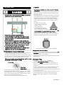
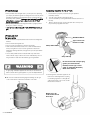
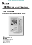
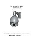
Use & Care Guide Manual de Uso y Cuidado English / Español Model/Modelo: 146.23680310 Items / Artículo: 640-05057375-7 Kenmore Liquid Propane Gas Grill ® Parrilla de LP gas P/N 50500050 Sears Brands Management Corporation Hoffman Estates, IL 60179 U.S.A. www.kenmore.com www.sears.com www.kmart.com ® DANGER If you smell gas: 1. 2. 3. 4. Shut off gas to the appliance. Extinguish any open flame. Open lid. If odor continues, keep away from the appliance and immediately call your gas supplier or your fire department. WARNING 1. Do not store or use gasoline or other flammable liquids or vapors in the vicinity of this or any other appliance. 2. An LP cylinder not connected for use shall not be stored in the vicinity of this or any other appliance. Installation Safety Precautions • Please read this User’s Manual in its entirety before using the grill. • Failure to follow the provided instruction can result in seriously bodily injury and/or property damage. • Some parts of this grill may have sharp edges. Please wear suitable protective gloves. • Use grill, as purchased, only with LP (propane) gas and the regulator/valve assembly supplied. • Grill installation must conform with local codes, or in their absence of local codes, with either the National Fuel Gas Code, ANSI Z223.1/ NFPA 54, Natural Gas and Propane Installation Code, CSA B149.1, or Propane Storage and Handling Code, B149.2, or the Standard for Recreational Vehicles, ANSI A 119.2/NFPA 1192, and CSA Z240 RV Series, Recreational Vehicle Code, as applicable. • All electrical accessories (such as rotisserie) must be electrically grounded in accordance with local codes, or National Electrical Code, ANSI / NFPA 70 or Canadian Electrical Code, CSA C22.1. Keep any electrical cords and/or fuel supply hoses away from any hot surfaces. • This grill is safety certified for use in the United States and/or Canada only. Do not modify for use in any other location. Modification will result in a safety hazard. IMPORTANT: This grill is intended for outdoor use only and is not intended to be installed in or on recreational vehicles or boats. NOTE TO INSTALLER: Leave this User’s Manual with the customer after delivery and/or installation. Call Grill Service Center For Help And Parts If you have questions or need assistance during assembly, please call 1-888-287-0735. You will be speaking to a representative of the grill manufacturer and not a Sears employee. To order new parts call Sears at 1-800-4-MY-HOME®. Product Record IMPORTANT: Fill out the product record information below. Model Number Safety Symbols The symbols and boxes shown below explain what each heading means. Read and follow all of the messages found throughout the manual. DANGER DANGER: Indicates an imminently hazardous situation which, if not avoided, will result in death or serious injury. Serial Number See rating label on grill for serial number. Date Purchased WARNING WARNING: Indicates an potentially hazardous situation which, if not avoided, could result in death or serious injury. CAUTION For residential use only. Do not use for commercial cooking. 2·146.23680310 NOTE TO CONSUMER: Leave this User’s Manual in a convenient place for future reference. CAUTION CAUTION: Indicates a potentially hazardous situation or unsafe practice which, if not avoided, may result in minor or moderate injury. TABLE OF CONTENTS WARRANTY Sears Installation Service For Your Safety . . . ..2 Grill Service Center. . . ..2 .2 Product Record Information . . . Installation Safety Precautions . . . ..2 Safety Symbols . . . ..2 Kenmore Grill Warranty . . . .4 Use and Care . . . . . . 5-11 Parts List . . . . . . 12 Parts Diagram . . . Before Assembly . . . For Sears professional installation of home appliances, garage door openers, water heaters, and other major home items, in the U.S.A. call 1-800-4-MY-HOME® . . 13 . . . 14-16 Assembly . . . . 17-27 Troubleshooting . . . . 28-30 CALIFORNIA PROP0SITION 65 1. Combustion by-products produced when using this product contain chemicals known to the State of California to cause cancer, birth defects, and other reproductive harm. 2. This Product contains chemicals, including lead and lead compounds, known to the State of California to cause cancer, birth defects or other reproductive harm. Wash your hands after using this product. Repair Protection Agreements Congratulations on making a smart purchase. Your new Kenmore® product is designed and manufactured for years of dependable operation. But like all products, it may require repair from time to time That's when having a Repair Protection Agreement can save you money and aggravation. Purchase a Repair Protection Agreement now and protect yourself from unexpected hassle and expense. Here’s what the Repair Protection Agreement* includes: Expert service by our 10,000 professional repair specialists Unlimited service and no charge for parts and labor on all covered repairs Product replacement up to $1500 if your covered product can't be fixed Discount of 25% from regular price of service and related installed parts not covered by the agreement; also, 25% off regular price of preventive maintenance check Fast help by phone - we call it Rapid Resolution phone support from a Sears representative. Think of us as a "talking owner's manual." Once you purchase the Repair Protection Agreement, a simple phone call is all that it takes for you to schedule service. You can call anytime day or night, or schedule a service appointment online. WARNING The Repair Protection Agreement is a risk-free purchase. If you cancel for any reason during the product warranty period, we will provide a full refund. Or, a prorated refund anytime after the product warranty period expires. Purchase your Repair Protection Agreement today! Some limitations and exclusions apply. For prices and additional information in the U.S.A. call 1-800-827-6655. *Coverage in Canada varies on some items. For full details call Sears Canada at 1-800-361-6665. 146.23680310 • 3 WARRANTY WARRANTY KENMORE GRILL WARRANTY ..2 ..2 KENMORE GRILL WARRANTY Kenmore One Year Limited Warranty One Year Full Warranty on Kenmore Grill .2 When installed, operated and maintained according to all supplied instructions, if this appliance fails due to a defect in material and workmanship within one year from the date. .of2 purchase, call 1-800-4-MY-HOME® to arrange for free repair or replacement if repair is unavailable. ..2 . 3 through will be replaced free of charge. After the first year For ten years from the date of purchase, any burner that rusts from the date of purchase, you are responsible for the . . .labor 4-10 cost to have it installed. . . . 11 All warranty coverage excludes ignitor batteries and grill part paint loss, discoloration or surface rusting, which are either . . 12 the warranty period, or are conditions that can be the result of expendable parts that can wear out from normal use within normal use, accident or improper maintenance. . . . 13-15 All warranty coverage is void if this product is ever used for other than private household purposes. . 27-29 This warranty covers ONLY defects in material and workmanship. Sears will NOT pay for: 1. Expendable items that can wear out from normal use within the warranty period, including but not limited to batteries, light bulbs and surface coatings or finishes. 2. A service technician to instruct the user in correct product installation, operation or maintenance. 3. A service technician to clean or maintain this product. 4. Damage to or failure of this product if it is not installed, operated or maintained according to the all instructions supplied with the product. 5. Damage to or failure of this product resulting from accident, abuse, misuse or use for other than its intended purpose. 6. Damage to or failure of this product caused by the use of detergents, cleaners, chemicals or utensils other than those recommended in all instructions supplied with the product. 7. Damage to or failure of parts or systems resulting from unauthorized modifications made to this product. Disclaimer of implied warranties; Limitation of remedies customer’s sole and exclusive remedy under this limited warranty shall be product repair as provided herein. Implied warranties, including warranties of merchantability or fitness for a particular purpose, are limited to one year or the shortest period allowed by law. Sears shall not be liable for incidental or consequential damages. Some states and provinces do not allow the exclusion or limitation of incidental or consequential damages, or limitation on the duration of implied warranties of merchantability or fitness, so these exclusions or limitations may not apply to you. This warranty applies only while this appliance is used in the United States. This warranty gives you specific legal rights, and you may also have other rights which vary from state to state. Sears Brands Management Corporation, Hoffman Estates, IL 60179 4 • 146.23686310 USE AND CARE DANGER • NEVER store a spare LP cylinder under or near the appliance or in an enclosed area. • Never fill a cylinder beyond 80% full. • If the information in the two points above is not followed exactly, a fire causing death or serious injury may occur. • An overfilled or improperly stored cylinder is a hazard due to possible gas release from the safety relief valve. This could cause an intense fire with risk of property damage, serious injury or death. • If you see, smell or hear gas escaping, immediately get away from the LP cylinder and appliance and call your fire department. LP Tank Removal, Transport And Storage • Turn OFF all control knobs and LP tank valve. Turn coupling nut counterclockwise by hand only - do not use tools to disconnect. Lift LP tank wire upward off of LP tank collar, then lift LP tank up and off of support bracket. Install safety cap onto LP tank valve. Always use cap and strap supplied with valve. Failure to use safety cap as directed may result in serious personal injury and/or property damage. LP Tank Valve Safety Cap Retainer Strap • A disconnected LP tank in storage or being transported must have a safety cap installed (as shown). Do not store an LP tank in enclosed spaces such as a carport, garage, porch, covered patio or other building. Never leave an LP tank inside a vehicle which may become overheated by the sun. • Do not store an LP tank in an area where children play. LP Cylinder • The LP cylinder used with your grill must meet the following requirements: • Use LP cylinders only with these required measurements: 12" (30.5cm) (diameter) x 18" (45.7 cm) (tall) with 20 lb. (9 kg.) Capacity maximum. • LP cylinders must be constructed and marked in accordance with specifications for LP cylinders of the U.S. Department of Transportation (DOT) or for Canada, CAN/CSA-B339, cylinders, spheres and tubes for transportation of dangerous goods. Transport Canada (TC). See LP cylinder collar for marking. • LP cylinder valve must have: • Type 1 outlet compatible with regulator or grill. • Safety relief valve. • UL listed Overfill Protection OPD Hand Wheel Device (OPD). This OPD safety feature is identified by a unique triangular hand wheel. Use only LP cylinders equipped with this type of valve. • LP cylinder must be arranged for vapor withdrawal and include collar to protect LP cylinder valve. Always keep LP cylinders in upright position during use, transit or storage. LP cylinder in upright position for vapor withdrawal LP (Liquefied Petroleum Gas) • LP gas is nontoxic, odorless and colorless when produced. For Your Safety, LP gas has been given an odor (similar to rotten cabbage) so that it can be smelled. • LP gas is highly flammable and may ignite unexpectedly when mixed with air. LP Cylinder Filling • Use only licensed and experienced dealers. • LP dealer must purge new cylinder before filling. • Dealer should NEVER fill LP cylinder more than 80% of LP cylinder volume. Volume of propane in cylinder will vary by temperature. • A frosty regulator indicates gas overfill. Immediately close LP cylinder valve and call local LP gas dealer for assistance. • Do not release liquid propane (LP) gas into the atmosphere. This is a hazardous practice. • To remove gas from LP cylinder, contact an LP dealer or call a local fire department for assistance. Check the telephone directory under “Gas Companies” for nearest certified LP dealers. 146.23680310 •5 LP Tank Exchange Connecting Regulator To The LP Tank • Many retailers that sell grills offer you the option of replacing your empty LP tank through an exchange service. Use only those reputable exchange companies that inspect, precision fill, test and certify their cylinders. Exchange your tank only for an OPD safety feature-equipped tank as described in the "LP Tank" section of this manual. • Always keep new and exchanged LP tanks in upright position during use, transit or storage. • Leak test new and exchanged LP tanks BEFORE connecting to grill. 1. LP tank must be properly secured onto grill. (Refer to assembly section.) 2. Turn all control knobs to the OFF position. 3. Turn LP tank OFF by turning OPD hand wheel clockwise to a full stop. 4. Remove the protective cap from LP tank valve. Always use cap and strap supplied with valve. ck LP Tank Leak Test For your safety • Leak test must be repeated each time LP tank is exchanged or refilled. • Do not smoke during leak test. • Do not use an open flame to check for gas leaks. • Grill must be leak tested outdoors in a well-ventilated area, away from ignition sources such as gas fired or electrical appliances. During leak test, keep grill away from open flames or sparks. • Use a clean paintbrush and a 50/50 mild soap and water solution. Brush soapy solution onto areas indicated by arrows in figure below. Leaks are indicated by growing bubbles. OPD Hand Wheel Type 1 outlet with thread on outside Safety Relief Valve Strap and Cap Do not insert a POL transport plug (plastic part with external threads) into the type 1 valve outlet. It will defeat the Safety Relief Valve feature. WARNING If “growing” bubbles appear do not use or move the LP tank. Contact an LP gas supplier or your fire department! ▲Do not use household cleaning agents. Damage to the gas train components (valve/hose/regulator) can result. 5. Hold regulator and insert nipple into LP tank valve. Hand-tighten the coupling nut, holding regulator in a straight line with LP tank valve so as not to crossththread the connection. Nipple has to be centered into the LP tank valve. 6 • 146.23680310 Leak Testing Valves, Hose and Regulator 1. Turn all grill control knobs to OFF. 2. Be sure regulator is tightly connected to LP tank. 3. Completely open LP tank valve by turning OPD hand wheel counterclockwise. If you hear a rushing sound, turn gas off immediately. There is a major leak at the connection. Correct before proceeding by calling Sears for replacement parts at 1-800-4-MY-HOME®. 4. Brush soapy solution onto areas where bubbles are shown in picture below: Hold coupling nut and regulator as shown for proper connection to LP tank valve. ▲ Never remove threaded orifice at end of valve. 6. Turn the coupling nut clockwise and tighten to a full stop. The regulator will seal on the back-check feature in the LP tank valve, resulting in some resistance. An additional one-half to three-quarters turn is required to complete the connection. Tighten by hand only - do not use tools. NOTE: If you cannot complete the connection, disconnect regulator and repeat steps 5 and 6. If you are still unable to complete the connection, do not use this regulator! Call 1-800-4-MY-HOME® for an identical replacement part. DANGER • Do not insert any tool or foreign object into the valve outlet or safety relief valve. You may damage the valve and cause a leak. Leaking propane may result in explosion, fire, severe personal injury, or death. WARNING • Outdoor gas appliance is not intended to be installed in or on a boat. • Outdoor gas appliance is not intended to be installed in or on an RV. • Never attempt to attach this grill to the self-contained LP gas system of a camper trailer or motor home. • Do not use grill until leak-tested. • If a leak is detected at any time, STOP and call the fire department. • If you cannot stop a gas leak, immediately close LP cylinder valve and call LP gas supplier or your fire department ! 5. If “growing” bubbles appear, there is a leak. Close LP tank valve immediately and retighten connections. If leaks cannot be stopped do not try to repair. Call for replacement parts at 1-800-4-MY-HOME®. 6. Always close LP tank valve after performing leak test by turning hand wheel clockwise. 146.23680310 • 7 WARNING For Safe Use of Your Grill and to Avoid Serious Injury: • Do not let children operate or play near grill. • Keep grill area clear and free from materials that burn. • Do not block holes in sides or back of grill. • Use grill only in well-ventilated space. NEVER use in enclosed space such as carport, garage, porch, covered patio, or under an overhead structure of any kind. • Do not use charcoal or ceramic briquets in a gas grill. • Use grill at least 3 ft. from any wall or surface. Maintain 10 ft. clearance to objects that can catch fire, or to sources of ignition such as pilot lights on water heaters, live electrical appliances, etc. Safety Tips ▲ Before opening LP cylinder valve, check the coupling nut for tightness. ▲ When grill is not in use, turn off all control knobs and LP cylinder valve. ▲ Never move grill while in operation or still hot. ▲ Use long-handled barbecue utensils and oven mitts to avoid burns and splatters. ▲ Maximum load for sideburner and side shelf is 10 lbs. ▲ The grease tray must be inserted into grill and emptied after each use. Do not remove grease tray until grill has completely cooled. ▲ Clean grill often, preferably after each cookout. If a bristle brush is used to clean any of the grill cooking surfaces, ensure no loose bristles remain on cooking surfaces prior to grilling. It is not recommended to clean cooking surfaces while grill is hot. ▲ If you notice grease or other hot material dripping from grill, determine the cause, correct it, then clean and inspect valve. Keep ventilation openings in cylinder enclosure (grill cart) free and clear of debris. ▲ Do not store objects or materials inside the grill cart enclosure that would block the flow of combustion air to the underside of either the control panel or the firebox bowl. ▲ The regulator may make a humming or whistling noise during operation. This will not affect safety or use of grill. ▲ If you have a grill problem see the "Troubleshooting Section". ▲ If the regulator frosts, turn off grill and LP cylinder valve immediately. This indicates a problem with the cylinder and it should not be used on any product. Return to supplier! CAUTION • Putting out grease fires by closing the lid is not possible. Grills are well ventilated for safety reasons. • Do not use water on a grease fire. Personal injury may result. If a grease fire develops, turn knobs and LP cylinder off. • Do not leave grill unattended while preheating or burning off food residue on HI. If grill has not been regularly cleaned, a grease fire can occur that may damage the product. • Apartment Dwellers: Check with management to learn the requirements and fire codes for using an LP gas grill in your apartment complex. If allowed, use outside on the ground floor with a three (3) foot clearance from walls or rails. Do not use on or under balconies. • NEVER attempt to light burner with lid closed. A buildup of non-ignited gas inside a closed grill is hazardous. • Never operate grill with LP cylinder out of correct position specified in assembly instructions. • Always close LP cylinder valve and remove coupling nut before moving LP cylinder from specified operation position. 8 • 146.23680310 Burner Igniter Lighting ▲Do not lean over grill while lighting. 1. Open lid during lighting. 2. Turn on valve from source or tank. 3. To ignite, turn Ignition Burner knob to HI. 4. Push and hold electronic ignition button. You will hear a clicking sound from the electrodes. 5. If ignition does not occur in 5 seconds, turn the burner controls OFF, wait 5 minutes, and repeat the lighting procedure. 6. To ignite any other Main Burner, turn knob to HI. 7. To ignite the Side Burner, follow steps 3-5 using the Side Burner knob. If igniter does not work, follow Match Lighting instructions. WARNING Turn controls and gas source or tank OFF when not in use. CAUTION If ignition does NOT occur in 5 seconds, turn the burner controls OFF, wait 5 minutes and repeat the lighting procedure. If the burner does not ignite with the valve open, gas will continue to flow out of the burner and could ignite with risk of injury. Match Lighting ▲Do not lean over grill while lighting. 1. Open lid during lighting. 2. Place match into match holder (hanging on left front leg). Light match, place into lighting hole on left side of firebox. 3. Turn right knob to HI position. Be sure burner lights and stay lit. 4. Light other burners by repeating step 3. Burner Flame Check • Remove cooking grates and heat diffusers. Light burners, turn knobs from HI to LO. You should see a smaller flame in LO position than seen on HI. Perform burner flame check on sideburner, also. Always check flame prior to each use. If only low flame is seen refer to "Sudden flame drop or low flame" in the Troubleshooting Section. HIGH HI LOW LO Turning Grill Off • Turn all knobs to OFF position. Turn LP cylinder off by turning Igniter Check • Turn gas off at LP cylinder. Press and hold electronic igniter button. " Clicking " should be heard and spark seen each time between collector box or burner and electrode. See "Troubleshooting" if no click or spark. Valve Check • Important: Make sure gas is off at LP cylinder before checking valves. Knobs lock in OFF position. To check valves, first push in knobs and release, knobs should spring back. If knobs do not spring back, replace valve assembly before using grill. Turn knobs to LOW position then turn back to OFF position. Valves should turn smoothly. Hose Check • Before each use, check to see if hoses are cut or worn. Replace damaged hoses before using grill. Use only valve/hose/regulator as specified in the parts list of this Use & Care Guide. General Grill Cleaning Sideburner Match Lighting 1. Open sideburner lid. Turn on gas at LP cylinder. 2. Place lit match near burner. 3. Turn sideburner knob to HI. Be sure burner lights and stays lit. • Do not mistake brown or black accumulation of grease and smoke for paint. Interiors of gas grills are not painted at the factory (and should never be painted). Apply a strong solution of detergent and water or use a grill cleaner with scrub brush on insides of grill lid and bottom. Rinse and allow to completely air dry. Do not apply a caustic grill/oven cleaner to painted surfaces. • Porcelain surfaces: Because of glass-like composition, most residue can be wiped away with baking soda/water solution or specially formulated cleaner. Use nonabrasive scouring powder for stubborn stains. • Painted surfaces: Wash with mild detergent or nonabrasive cleaner and warm soapy water. Wipe dry with a soft nonabrasive cloth. . • Stainless steel surfaces: To maintain your grill’s high quality appearance, wash with mild detergent and warm soapy water and wipe dry with a soft cloth after each use. Baked-on grease deposits may require the use of an abrasive plastic cleaning pad. Use only in direction of brushed finish to avoid damage. Do not use abrasive pad on areas with graphics. • Cooking surfaces: If a bristle brush is used to clean any of the grill cooking surfaces, ensure no loose bristles remain on cooking surfaces prior to grilling. It is not recommended to clean cooking surfaces while grill is hot. 146.23680310 • 9 Cleaning the Burner Assembly CAUTION WARNING SPIDER ALERT! SPIDER ALERT! IMPORTANT: Always ensure that the venturi burner tubes are clean. A venturi burner tube has a narrow area in which spiders tend to build nests. Follow these instructions to clean and/or replace parts of burner assembly or if you have trouble igniting grill. 1. Turn gas off at control knobs and LP cylinder. 2. Remove cooking grates and heat diffusers. 3. Remove cotter pin from rear of burners. 4. Carefully lift each burner up and away from valve openings. . We suggest three ways to clean the burner tubes. Use the one easiest for you. (A) Bend a stiff wire (a light weight coat hanger works well) into a small hook. Run the hook through each burner tube several times. If you notice that your grill is getting hard to light or that the flame isn’t as strong as it should be, take the time to check and clean the venturi’s. clean the venturi’s. VALVE CONTROL PANEL SPIDER WEBS INSIDE VENTURI BURNER Spiders or small insects have been known to create “flashback” problems. The spiders spin webs, build nests and lay eggs in the grill’s venturi tube(s) obstructing the flow of gas to the burner. The backed-up gas can ignite in the venturi behind the control panel. This is known as a flashback and it can damage your grill and even cause injury. (B) Use a narrow bottle brush with a flexible handle (do not use a brass wire brush), run the brush through each burner tube several times. (C) Wear eye protection: Use an air hose to force air into the burner tube and out the burner ports. Check each port to make sure air comes out each hole. 5. Wire brush entire outer surface of burner to remove food residue and dirt. 6. Clean any blocked ports with a stiff wire such as an open paper clip. 7. Check burner for damage, due to normal wear and corrosion some holes may become enlarged. If any large cracks or holes are found replace burner. VERY IMPORTANT: Burner tubes must reengage valve openings. See illustrations below. To prevent flashbacks and ensure good performance the burner and venturi assembly should be removed from the grill and cleaned .before use whenever the grill has been idle for an extended period. 8. Carefully replace burners. 9. Attach burners to brackets with cotter pin. 10. Reposition carryover tubes and attach to burners. Replace heat diffusers and cooking grates. Storing Your Grill •Clean cooking grates. •Store in dry location. •When LP cylinder is connected to grill, store outdoors in a well-ventilated space and out of reach of children. •Cover grill if stored outdoors. Choose from a variety of grill covers offered by manufacturer once available. •Store grill indoors ONLY if LP cylinder is turned off and Disconnected, remove from grill and stored outdoors. • When removing grill from storage, follow “Cleaning the Burner Assembly instructions before starting grill. 10 • 146.23680310 Electrode Indirect Cooking Poultry and large cuts of meat cook slowly to perfection on the grill by indirect heat. Place food over unlit burner(s); the heat from lit burners circulates gently throughout the grill, cooking meat or poultry without the touch of a direct flame. This method greatly reduces flare-ups when cooking extra fatty cuts because there is no direct flame to ignite the fats and juices that drip during cooking. 1 Burner Cooking Cook with direct or indirect heat. Best for smaller meals or foods. Consumes less fuel. Indirect Cooking Instructions • Always cook with the lid closed. • Due to weather conditions, cooking times may vary. During cold and windy conditions the temperature setting may need to be increased to insure sufficient cooking temperature. • Place food over over unlit burner(s). 2 Burner Cooking Great indirect cooking on low. Produces slow, even heating. Ideal for slow roasting and baking. Food Safety Food safety is a very important part of enjoying the outdoor cooking experience. To keep food safe from harmful bacteria, follow these four basic steps: Clean: Wash hands, utensils, and surfaces with hot soapy water before and after handling raw meat and poultry. Separate: Separate raw meats and poultry from ready-to-eat foods to avoid cross contamination. Use a clean platter and utensils when removing cooked foods. Cook: Cook meat and poultry thoroughly to kill bacteria. Use a thermometer to ensure proper internal food temperatures. Chill: Refrigerate prepared foods and leftovers promptly. For more information call: USDA Meat and Poultry Hotline at 1-800-535-4555 (In Washington, DC (202) 720-3333, 10:00 am 4:00 pm EST). How To Tell If Meat Is Grilled Thoroughly • Meat and poultry cooked on a grill often browns very fast on the outside. Use a meat thermometer to be sure food has reached a safe internal temperature, and cut into food to check for visual signs of doneness. • Whole poultry should reach 180° F; breasts, 170° F. Juices should run clear and flesh should not be pink. • Hamburgers made of any ground meat or poultry should reach 160° F, and be brown in the middle with no pink juices Beef, veal and lamb steaks, roasts and chops can be cooked to 145° F. All cuts of pork should reach 160° F. • NEVER partially grill meat or poultry and finish cooking later. Cook food completely to destroy harmful bacteria. • When reheating takeout foods or fully cooked meats like hot dogs, grill to 165° F, or until steaming hot. WARNING: To ensure that it is safe to eat, food must be cooked to the minimum internal temperatures listed in the table below. USDA* Recommended Safe Minimum Internal Temperatures USDA* Minimum Internal Beef, Veal, LambSafe and Pork – Whole Cuts**Temperatures 145° F Fish Fish 145° F 145°F Pork Beef, Veal, Lamb and Pork – Ground 160° F 160°F Egg Dishes Egg Dishes 160° F 160°F Steaks Roasts Beef,– Whole, Pieces & 165° F Turkey, and Chicken & of Duck 145°F Veal or Lamb Ground Ground or Lamb 160°F * United Beef, StatesVeal Department of Agriculture Whole Poultry (Turkey, **Allow meat to rest three minutes before carving or consuming. Chicken, Duck, etc.) 165°F Ground or Pieces Poultry 165°F (Chicken Breast, etc.) *United States Department of Agriculture 146.23680310 • 11 PARTS LIST Key Key 1 21 2 3 3 4 4 55 66 77 88 99 10 10 11 11 12 1213 1314 1415 1516 17 16 18 17 19 18 20 1921 2022 2123 2224 25 23 26 24 27 2528 2629 2730 31 32 33 34 35 36 37 38 39 40 41 Description Qty Qty Description Side Burner Lid Part Number Key Description 1 40800064 28 1 40800119 29 1 40800121 30 1 40800120 31 1 40800063 32 1 40300055 33 1 Right Side Shelf Fascia, 45 1 CLIP, F/ GREASE CUP Main Burner GREASE CUP 46 1 Electrode, BurnerTHUMBSCREW 47 1MainTANK 1 40700046 34 1 Electronic Ignition Module 1 40800122 1 2 Cooking Grate, Side Burner 1 Side Burner 1 Ignitor Wire, Side Burner 1 Side 1 Burner Base Right 2 Side Shelf 1 Panel Control 1 Gas Valve, Main Burner 1 Manifold, Main Burner 1 Side1 Burner Hose Gas1 Valve, Side Burner 1 Regulator 1 Knob Bezel Control 2 Control Knob 2 Gas Tank Holder 1 Bottom Shelf 1 Hex1Nut Axle 3 Washer 1 Rod Axle 2 Wheel 1 Lid 1 Rubber Bumper, Lid 1 Bezel, 1 Lid Handle Lid 4Handle Spacers Lid 4Handle 1 1 1Not Pictured 1Hardware Pack 1Manual 1 1 Pictured Not 1 Hardware Pack 1 Manual 1 1 Warming Rack Qty Part Number 1 40700040 2 40300101 5 40800023 4 50300024 5 40700125 1 40200085 Grease Tray 1 50500015 35 Back Rail 1 50500040 50500016 36 Right Leg Assembly 1 50500033 5 40900205 37 Side Panel 2 40700059 1 50300041 38 Hose Fixed PinHARDWARE PACK 1 40800134 1 40900210 39 1 40900209 1 42 3 HEAT DIFFUSERS Cooking Grate 43 Diffuser 3 COOKING GRATE Heat 44 1 SWING AWAY GRATE Flame Carry Over Tube Not Pictured 40 1 Cotter Pin1 PRODUCT MANUAL, ENGLISH 11 Rotate Rod, 2 1 LidPRODUCT MANUAL, SPANISH 40700080 408D00115 41 Logo 1 40800106 6 40900036 42 Temperature Gauge 1 40900201 6 50500042 43 Firebox 1 50500009 1 40800130 44 Grease Cup 1 40800026 1 50500038 45 Grease Cup Clip 1 40800131 1 110011 46 Rubber Bumper, Firebox 2 40700099 1 110018 47 Left Side Shelf 1 40800040 1 408D00125 48 Fascia, Left Side Shelf 1 40700040 2 40800124 49 Left Leg Assembly 1 50500026 1 50500004 50 Match Holder Bracket 1 40800129 2 40700103 51 Match Holder 1 40800128 2 40900013 52 Leg Extender 2 40800127 2 40700111 53 Tank baffle 1 40800090 1 40900012 54 Front Panel 2 50500041 1 50500049 1 50500050 1 40700218 1 40700219 110050 If you are missing hardware or have damaged parts after unpacking grill, call 1-888-287-0735 for replacement. To order replacement parts after using grill, call 1-800-4-MY-HOME® NOTE: Some grill parts shown in the assembly steps may differ slightly in appearance from: those on your particular grill model. However, the method of assembly remains the same.: 12·146.23680310 PARTS DIAGRAM PARTS DIAGRAM 146.23680310 • 13 BEFORE ASSEMBLY READ AND FOLLOW THE INSTRUCTIONS BELOW TO CORRECTLY UNPACK GRILL PARTS FROM SHIPPING BOX. Step 1: Open shipping box by slicing down its edges with a box cutter, take out hardware pack and manual from top. Remove all packing material and parts from top and front of lid. Left Leg Assembly Right Side Panel (Pre-Assembly) 14·146.23680310 BEFORE ASSEMBLY Step 2: Remove the left and right Styrofoam from Grill Head. Open grill lid and take out the boxes. Remove all packing material, and take all parts out of boxes. 146.23680310·15 BEFORE ASSEMBLY Step 3: Take our the Cooking Grates, Warming Rack, Grease Accumulate Panel, Front panel, Left Side Panel and Axle Rod from firebox. 16 • 146.23680310 ASSEMBLY CAREFULLY READ AND PERFORM ALL ASSEMBLY INSTRUCTIONS ON THE FOLLOWING PAGES. Tools Required: Adjustable wrench (not provided) Screwdriver (not provided) 7/16” Combination wrench (not provided) The following hardware is provided in a blister pack for convenient use. M4X10 screw Qty: Qty: 27 28 pcs pcs AAA Battery Qty: Qty: 11 pc pc M5X10 screw Qty: Qty: 64pcs pcs M5 flat washer Qty: Qty: 44 pcs pcs M6X13 screw Qty: Qty: 16 16pcs pcs M6 compression washer Qty: Qty: 88 pcs pcs 146.23680310 • 17 1 2 Bottom Shelf □ Attach left side panel to left Frame (marked L) with (4) M4x10 screws to construct the Left Panel Assembly . The Right Panel Assembly comes pre-constructed. □ Attach sides of bottom shelf to left and right panel assemblies with (6) M4x10 screws. Do not fully tighten at this time. Cart will not be level. This will be corrected when the front panels and wheels are installed. M4X10 screws Qty: 10pcs side panel Rear Front Left Panel Assembly 18·146.23680310 Bottom Shelf Right Panel Assembly Cart □ Turn cart upside down. Align the bottom shelf side holes with leg holes. □ Attach sides of bottom shelf to four legs with (4) M6x13 screws. Fully tighten all shelf screws, top and bottom. □ Remove hitch pin, nut and washer from axle. Insert axle rod through a wheel, through both right leg axle holes, and through other wheel. □ Attach with (1) Axle washer, nut and hitch pin. Assemble wheels with “cone” side against legs. □ Hammer leg extenders onto left legs. M6X13 screws Qty: 4 pcs Hitch Pin Axle Rod Nut Axle Washer 146.23680310·19 Front Panels □ Attach one front panel to lower half of cart with (4) M4x10 screws. □ Attach another front panel to upper half of cart with (4) M4x10 screws. □ Attach tank baffle to front panels and bottom shelf with (2) M4x10 screws. □ Attach two front panels together in the center with (1) M4x10 screw. □ Attach bottom front panel to cart in the center with (1) M4x10 screw. M4X10 screws 20·146.23680310 Qty: 12 pcs Grill Head to Cart □ This step requires two people to lift and position grill head onto cart. □ Remove the tie wraps securing regulator hose to underside of grill head. Pull hose and igniter wires out to side of grill head. □ Carefully lower the grill head onto the cart. Make sure the regulator hose and igniter wires are hanging outside the cart. Open lid and attach head to cart with (4) M6x13 screws and M6 compression washers. M6X13 screws Qty: 4 pcs M6 compression washers Qty: 4 pcs 146.23680310·21 Left Side Shelf □ Attach fascia to left side shelf with (2) M5x10 screws and M5 flat washers. (A) □ Hang shelf onto brackets on left side of firebox. □ Attach shelf to firebox as follows: - From inside to outside of firebox with (2) M6x13 screws and M6 compression washers. (B) - From outside to inside of firebox with (2) M6x13 screws. (C) □ Attach fascia to control panel with (1) M4x10 screw. (C) M5X10 screws Qty: 2 pcs M5 flat washers Qty: 2 pcs A M6X13 screws Qty: 4 pcs M6 compression washers Qty: 2 pcs M4X10 screws Qty: 1 pc B 22·146.23680310 C Right Side Shelf □ Remove side burner grate from side burner before assembling and attaching the right side shelf. □ Attach fascia to right side shelf with (2) M5x10 screws, and M5 flat washers.(A) □ Hang right side shelf onto the brackets on right side of firebox. □ Attach shelf to firebox as follows: - From inside to outside of firebox with (2) M6x13 screws and M6 compression washers.(B) - From outside to inside of firebox with (2) M6x13 screws. (C) □ Attach fascia to control panel with (1) M4x10 screw. (C) M5X10 screws Qty: 2 pcs M6X13 screws Qty: 4 pcs M5 flat washers Qty: 2 pcs M6 compression washers Qty: 2 pcs A M4X10 screws Qty: 1 pc B C 146.23680310·23 Side burner □ Loosen side burner in side shelf. (B ). To loosen, unscrew and remove two front screws holding side burner in place. (A). Note: Do not loosen electrode screw. □ Remove the 2 pre-installed screws from the valve stem and set them aside. (C) □ Insert valve stem through hole in fascia. (D) Attach bezel to fascia and valve face with previously removed 2 screws. Attach bezel with black mark facing up (E). □ Place side burner tube over the valve, making sure that valve is inside side burner tube. (F) □ Push control knob onto side burner valve stem. (G) □ Reattach side burner to side burner shelf with the 2 previously removed screws. Replace side burner grate. (H) □ Connect both igniter wires to the igniter module on the inside of the right fascia. To connect, push igniter wire tips onto pins in igniter module.(I) □ Unscrew igniter cap from control panel. Insert (1) AAA battery (provided in blister pack) into battery slot with positive end (+) facing outward. Screw igniter cap back onto panel. (J) A C E 24·146.23680310 B D F G H I J Heat Diffusers, Cooking Grates and Warming Rack □ Place heat diffusers over burners. Diffusers will fit in firebox in either direction. Fit tabs in firebox front through slots in diffuser tips. Fit diffuser tips inside tabs in firebox rear. □ Place cooking grates onto grate rests. □ Insert warming rack into brackets at top of firebox as shown. 146.23680310·25 Grease Tray, Grease Cup and Back Brace □ Slide grease tray into bottom of firebox from back. Make sure the grease drainage hole is on the right side, as seen from the back of the grill.(A) □ Hang grease cup clip from bottom of grease tray. Place grease cup into grease cup clip.(B) □ Attach back brace to top of cart with (4) M4x10 screws.(C) A C 26·146.23680310 B □ LP tank is sold separately. Use only with an OPD (Overfill Protection Device) equipped LP tank. Fill and leak check before attaching to grill and regulator. Place LP tank into hole in bottom shelf with tank collar opening facing to the left, as seen from the back of the grill. Raise tank holder to hold LP tank securely in place. □ Feed the regulator hose through the hose bracket on Right Front Leg and fix with cotter pin. CAUTION Failure to install grease cup clip and cup will cause hot grease to drip from bottom of grill with risk of fire or property damage. CAUTION Failure to install tank correctly may allow gas hose to be damaged in operation. 146.23680310·27 EMERGENCIES: If a gas leak cannot be stopped, or a fire occurs due to gas leakage, call the fire department. Problem Gas leaking from cracked/cut/burned hose. Possible Cause • Damaged hose. Gas leaking from LP cylinder. • Mechanical failure due to rusting or mishandling. Gas leaking from LP cylinder valve. • Failure of cylinder valve from mishandling or mechanical failure. Gas leaking between LP • Improper installation, connection not cylinder and regulator tight, failure of rubber seal. connection. Fire coming through control panel. • Fire in burner tube section of burner due to blockage. Grease fire or continuous excessive flames above cooking surface • Too much grease buildup in burner area. Prevention / Solution •Turn off gas at LP cylinder or at source on natural gas systems. If the hose is cracked or cut but not burned, simply replace valve / hose / regulator. If the hose is burned, the cause could be other than a faulty valve/hose/regulator. Discontinue use of grill until a plumber or gas technician has investigated and corrected the problem. • Replace LP cylinder. • Turn off LP cylinder valve. Return LP cylinder to gas supplier. •Turn off LP cylinder valve. Remove regulator from cylinder and visually inspect rubber seal for damage. See LP Cylinder Leak Test and Connecting Regulator to the LP Cylinder. •Turn off control knobs and LP cylinder valve. Leave lid open to allow flames to die down. After fire is out and grill is cold, remove burner and inspect for spider nests or rust. See Spider Alert and Cleaning the Burner Assembly sections of this Use & Care Guide. • Turn off control knobs and LP cylinder valve. Leave lid open to allow flames to die down. After cooling, clean food particles and excess grease from inside firebox area, grease tray, and other surfaces. Troubleshooting Problem Possible Cause Prevention/Solution GAS ISSUES: • See instructions on control panel and in Use and Care section. Burner(s) will not light • Trying to light wrong burner. using igniter. (See Electronic • Burner not engaged with control Ignition valve. Troubleshooting also) • Obstruction in burner. Continued on next page. • No gas flow. • Ensure burner tubes are not obstructed with spider webs or other matter. See cleaning section of Use and Care. • Make sure LP cylinder is not empty. If LP cylinder is not empty, refer to “Sudden drop in gas flow.” • Vapor lock at coupling nut to LP cylinder. • Turn off knobs and disconnect coupling nut from LP cylinder. Reconnect and retry. • Coupling nut and LP cylinder valve not fully connected. • Turn the coupling nut approximately one-half to three-quarters additional turn until solid stop. Tighten by hand only - do not use tools. • Replace electrode(s). • Electrode cracked or broken; “sparks at crack. • Electrode tip not in proper position. 28·146.23680310 • Make sure valves are positioned inside of burner tubes. Main Burners and side burner: • Tip of electrode should be pointing toward gas port opening on burner. The distance should be 1/8” to 1/4”. Adjust if necessary. • Wire and/or electrode covered with cooking residue. • Wires are loose or disconnected. • Wires are shorting (sparking) between igniter and electrode. • Clean wire and/or electrode with rubbing alcohol and clean swab. • Reconnect wires or replace electrode/wire assembly. • Replace igniter wire/electrode assembly. • Dead battery. • Replace with a new AAA-size alkaline battery. Troubleshooting (continued) Problem Possible Cause Burner(s) will not light using igniter. (See Electronic Ignition Troubleshooting also) ELECTRONIC IGNITION: • No spark, no ignition noise. • No spark, some ignition noise. Pro • Sparks, but not at electrode or at full strength. Burner(s) will not match light. • See “GAS ISSUES:” on previous page. • Match will not reach. • Improper method of match-lighting. Sudden drop in gas flow or low flame. • Out of gas. • Excess flow valve tripped. • Vapor lock at coupling nut/LP cylinder connection. Prevention / Solution Prevention/Solution • See Section I of Electronic Ignition System. • See Section II of Electronic Ignition System. • See Section III of Electronic Ignition System. • Use long-stem match (fireplace match). • See “Match-Lighting” section of Use and Care. • Check for gas in LP cylinder. •Turn off knobs, wait 30 seconds and light grill. If flames are still low, turn off knobs and LP cylinder valve. Disconnect regulator. Reconnect regulator and leak-test. Turn on LP cylinder valve, wait 30 seconds and then light grill. •Turn off knobs and LP cylinder valve. Disconnect coupling nut from cylinder. Reconnect and retry. Flames blow out. • High or gusting winds. • Low on LP gas. • Excess flow valve tripped. • Turn front of grill to face wind or increase flame height. • Refill LP cylinder. • Refer to “Sudden drop in gas flow” above. Flare-up. • Grease buildup. • Excessive fat in meat. • Excessive cooking temperature. • Clean burners and inside of grill/firebox. • Trim fat from meat before grilling. • Adjust (lower) temperature accordingly. Persistent grease fire. • Grease trapped by food buildup around burner system. •Turn knobs to OFF. Turn gas off at LP cylinder. Leave lid in position and let fire burn out. After grill cools, remove and clean all parts. • Burner and/or burner tubes are Flashback… blocked. (fire in burner tube(s)). • Turn knobs to OFF. Clean burner and/or burner tubes. See burner cleaning section of Use and Care. Unable to fill LP cylinder. • Some dealers have older fill nozzles with worn threads. • The worn nozzles don’t have enough “bite” to engage the valve. Try a second LP dealer. One burner does not light from other burner(s). • Grease buildup or food particles in end(s) of carryover tube(s). • Clean carry-over tube(s) with wire brush. 146.23680310·29 Troubleshooting - Electronic Ignition Problem Possible Cause • Battery not installed SECTION I No sparks appear at properly. any electrodes when • Dead battery. control knob turned to HI: no noise can be heard from spark • Button assembly not module. installed properly. • Faulty spark module. SECTION II No sparks appear at any electrodes when control knob turned to HI; noise can be heard from spark module. SECTION III Sparks are present but not at all electrodes and/or not at full strength • Check battery orientation. • Has battery been used previously? Prevention / Solution Preventio • Install battery (make sure that “+” and “-” connectors are oriented correctly, with “+” end up and “-” end down.) • Replace battery with new AAA-size alkaline battery. • Check to insure threads are properly engaged. Button • Unscrew button cap assembly and reinstall, should travel up and down making sure threads are aligned and engaged without binding. fully. • If no sparks are generated with new battery and good wire connections, module is faulty. • Replace spark module assembly. • Are output connections on and tight? • Remove and reconnect all output • Output lead connections not connected. • Are output connections on and tight? • Remove and reconnect all output connections at module and electrodes. • Electrical arc between output wires and grill frame. • If possible, observe grill in dark location. Operate ignition system and look for arcing between output wires and grill frame. • If sparks are observed other than from burner(s), wire insulation may be damaged. Replace wires. • Weak battery. • All sparks present but weak or at slow rate. • Replace battery with a new AAA-size alkaline battery. • Electrodes are wet. • Has moisture accumulated on electrode and/or in burner ports? • Use paper towel to remove moisture. • Inspect electrodes for cracks. • Replace cracked or broken electrodes. • Output lead connections not connected. • Electrode(s) cracked or broken; sparks appear where cracked. 30·146.23680310 Check Item connections at module and electrodes.