1
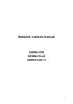
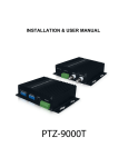
IR HIGH SPEED DOME USER MANUAL Before installation and use this speed dome, do read the manual and keep this manual for future use SPEED DOME CAMERA INDEX 1. Product Introduction…………………………………….………….………...…….………... 2 1.1 1.2 1.3 1.4 1.5 Safety Attention Notes …………………………………………………………………………2 Cautions ……………………………………………………………………………………………2 Function……………………………………………………………………………………………2 Speed Dome Dimension Chart………………………………………………………………. …3 Specification ………………………………………………………………………………………4 1.6 Packing and Accessories …………………………………………………………….....5 2. Speed dome Setting ………………………………………………………………………...5 2.1 Switch Position setting ……………………………………………………………………………..5 2.2 Baud Rate Setting …………………………………………………………………………….....5 2.3 Communication protocol Setting ……………………………………………………………5 2.4 Address Setting……………………………………………………………………….......6 2.5 Alarm Connection ……………………………………………………………………….6 2.6 Dome camera Installation and Connection………………………………………….7 3. OSD Setting …………………………………………………………………………… 7 3.1OSD Index………………………………………………………………………………..8 3.2 Operation ………………………………………………………………………………..9 3.2.1 Selecting aim item…………………………………………………………………9 3.2.2 Parameter Setting …………………………………………………………………9 3.3 System Setting ………………………………………………………………………….9 3.3.1 System Display Setting …………………………………………………………...9 3.3.2 System State Setting ……………………………………………………………9 A: Power up Act ……………………………………………………………………….10 B:Leisure Act……………………………………………………………………………10 C:Leisure Time ………………………………………………………………………...10 D:Reset Password …………………………………………………………………10 E: Default Restoration …………………………………………………………………10 3.4Camera Setting ……..…………………………………………………………………….11 3.5 Speed dome function setting……………………………………………………………11 3.5.1Scan setup ………………………………………………………………………...12 A:Pattern Scan setting …………………………………………………………………12 B: Tour Scan setting…………………………………………………………………….12 C: 360 °Scan Setting …………………………………………………………………..13 D:Limit Scan setting …………………………………………………………………….13 3.5.2Auto Flip ……………………………………………………………………………..14 3.5.3Home Place………………………………………………………………………….14 3.6 Alarm Setup ………………………………………………………………… …14 3.7 Preset Position title setting…………….……………………………………………….14 3.8 Preset positon shortcut Key…………………………………………………………………15 4. Exception handling table………………………………………………………………16-17 5. Housing cleaning ………………………………………………………………………………16 6. Speed dome Maintenance…………………………………………………………………….16 Annex: Sony/CNB/LG camera menu ……………………………………………………………..17-19 1 SPEED DOME CAMERA 1. Product Introduction This series of products using the most stable high-performance digital DSP design, some of the main component is famous brand such as Motor-driver, zoom module , electronic slip ring . our speed dome has the perfect design and easy installation ,which is an inevitable trend for the high-tech products . It can quickly and accurately position and track the target, It can be no blind spot in the all-round goal of a 24-hour surveillance . This product can be widely used in smart buildings, bank security, urban roads, airport terminals ect which can meet any of the diversification request for the square, 1. 1Safety Attention Notes A. B. C. D. E. F. Please read the instructions thoroughly before installing or operating the unit . Please follow the safety operating standard when installing Only professional and experienced staff can do the installation and maintenance work Use reliable tools, poor tools can cause danger Make sure the using environment meet requirements of the product Please check the strength and toughness of the installation base, the base must bear 4 times the total weight of speed dome and accessories. G. Please keep all packaging for future packaging and transportation. 1.2 Cautions A.Please do not install the speed dome in the inflammable and explosive area. B. Please do not put the speed dome in the unstable table or mounting bracket. C. Please prevent all liquids or other contaminating material from entering into the dome housing. D. Do not use the wrong power adapter ,the speed dome power supply isDC12V. E. RS-485, blue wire for 485+ (A), green wire for 485-(B) F. Please do not turn on the power before finishing installation G. Please do not open the speed dome or repair by yourself . H. Please do not clean the unit by Corrosive detergent . I. Avoid shooting very bright objects directly into the camera‟s CCD (such as the sun or light fittings) J. Please prevent over weight impact or shock K. Please read manual book thoroughly before installation. 1.3 Function Horizontal rotation speed 0.1-280°/s,Vertical rotation speed 0.1-240°/s 255 preset position some of them can set title. 2 Scan mode , 4 Pattern , 4 Tour . 4 CH Alarm in , 1CH Alarm out . RS485 , Pelco D ,P English OSD menu Leisure Act setting function Title ,coordinate ,Temperature , zoom display Aluminum Alloy , IP66 Waterproof housing Built-in temperature control system Outdoor and Indoor mounting Power supply : DC24V ,low consumption 2 SPEED DOME CAMERA 1.4 Speed Dome Dimension Chart SPEED DOME ENTIRETY CHART M ounting bracket BNC videoport DC12V pow er s upplyport Bolt(M 4) RS 485 signal control port Connection flange Alarm input and output cable Hous ing M ini board Speed dom e cover Vertical m otor Horizontal m otor Trans port hous ing IR LE D Cam era m odule 3 SPEED DOME CAMERA 1.5 Specification SPECIFICATION OSD MENU ENGLISH PRESET POSITION 255 PCS(SONY,HITACHI);64PCS(CNB,LG etc ) SCAN AUTO SCAN ,LIMIT SCAN (Speed adjustable) TOUR SCAN 4 TOUR ,16 Preset position per tour ,speed and dwell time can be adjustable PATTERN SCAN 4 PATTERN , 15minutes recording for each pattern ALARM 4 CH ALARM IN 1 CH ALARM OUT PRESET RANGE 1--255 COMMUNICATION RS-485 BAUD RATE COMMUNICATION PROTOCOL DWELL SETUP Title Display Camera ID ZOOM 2400/4800/9600/19200, Pelco-P/D Home place/Auto Scan/Tour scan/Pattern scan Display or hide the title, the title can be 16 letters , number MAX. Display /Hide Display Mechanical parameters Horizontal rotation range 0o --360o Horizontal rotation speed 0.1 o --200 o /s Tilt rotation range 0.1---90o Auto Flip180o Tilt rotation speed 0.1 o --120 o /s Positioning accuracy 0.1o Other Parameters Housing Material Aluminum alloy Waterproof standard IP66 Operating Temperature -20oC---65oC Operating humidity Less than 95% POWER Supply DC12V/5A Mounting bracket ceiling or wall mounting Gross weight 4kg 4 SPEED DOME CAMERA 1.6 Packing and Accessories ID Item Quantity 1 Manual 1 piece 2 Guarantee card 1 piece 3 Passed card 1 piece 4 Glove 1 pair 5 Screwdriver 1 piece 6 Screw for camera 4 piece 7 Screw for Bracket 4 piece 2 . Speed dome Setting 2.1 Switch Position Setting This speed dome‟s address code can be setted in the software by DVR or joystick.No need to set by change the code inside the speed dome itself.The detail operation please refer to page 13. SW1 SW2 2.2 Baud Rate Setting This speed dome‟s baud rate can be setted in the software by DVR or joystick.No need to set by change the code inside the speed dome itself.The detail operation please refer to page 13. Speed dome can automatically recognize the Pelco-D or Pelco-P so only to set the baud rate and Address to make speed dome working . Baud rate is setted by 1&2 bits in SW2. The relative code switch setting below for reference, the default setting is 2400 bps SW2 Baud Rate Code bit on SW2 2400 OFF OFF 4800 ON OFF 9600 OFF ON 19200 ON ON 1 2 2.3 Communication protocol setting The communication is setted by 1/2 bits in SW2.Speed dome can automatically recognize Pelco-D & Pelco-P , so the speed dome can work without setting communication protocol. The default 5 SPEED DOME CAMERA setting is Pelco-D . 2.4 Address Setting The bits in SW2 are used to set Dome address . (see following figure) SW1 Address CODE BIT SETTING 1 2 3 4 5 6 7 8 0 OFF OFF OFF OFF OFF OFF OFF OFF 1 ON OFF OFF OFF OFF OFF OFF OFF 2 OFF ON OFF OFF OFF OFF OFF OFF 3 ON ON OFF OFF OFF OFF OFF OFF 4 OFF OFF ON OFF OFF OFF OFF OFF 5 ON OFF ON OFF OFF OFF OFF OFF 6 OFF ON ON OFF OFF OFF OFF OFF 7 ON ON ON OFF OFF OFF OFF OFF 8 OFF OFF OFF ON OFF OFF OFF OFF 9 ON OFF OFF ON OFF OFF OFF OFF 10 OFF ON OFF ON OFF OFF OFF OFF 11 ON ON OFF ON OFF OFF OFF OFF 12 OFF OFF ON ON OFF OFF OFF OFF ON ON ON ON …… 255 ON ON ON ON If using other controller to control speed dome, The communication protocol(speed dome recognize itself) baud rate and dome address should be setted correctly , Some times should be increase 1 or decrease 1 on the address code because of different address code from different factory . eg , dome address is 2, then have to set the address code as 3 on the DVR , then can use the DVR to control the speed dome properly . 2.5 Alarm connection This speed dome can connect 4CH alarm input and1 CH output. Alarm cable COM black AL1 purple K1 AL2 light green K2 AL3 grey K3 AL4 orange K4 red Alarm light、alarm bell green 6 SPEED DOME CAMERA Remark : Alarm output switch value should be on,k1-k4 is switch value signal for outside 2.6. Dome camera Installation and connection : 2.6.1 Caution Before Installation: 1.The installation should be operated by the engineers or a qualified CCTV expert. 2.The correct connection way please check the installation pictures and installation specification 3.Pleases do wear glove before installation .Do not touch the speed dome and shell directly with metal ,hardware or hand to avoid scratching the speed dome housing. 4. Pleases lock the security wire when installing the transparent dome to avoid the unexpected scratch. 5.Please clean the transparent dome cover with soft paper or cloth after the installation . 2.6.2 The request of installation Please check the accessories are complete or not after open the package . Please check the application place and mounting way match the camera „s requirement. The installation should be operated by CCTV expert obey the instructions in case of causing a trouble Please do use the proper tools, such as the screwdriver . Take out the camera module from the upper housing, check the address code right or not and then press the upper housing and lock the four M3X14 screw on the bottom board . 3.OSD setting When the power of the speed dome is on, it will show the speed dome camera basic information :such as protocol ,baud rate , address code , after self-inspection all the information will appear in 5 seconds ( user can see the setting information below ) PROTOCOL: PELCO-D COMM: 2400, N , 8.1 ADDRESS :001 FIRMWARE VER :11.0IR RERRENCE IS OK CAMERA IS OK When above information appear after self-inspection, that means the speed dome can work well , it can be controlled well by Keyboard .Press 95+ preset to enter main menu , change menu by joystick up , down , left , right . the key function of the keyboard is as following table. Serial number keyboard Function function of OSD 1 joystick up The cursor shift up 2 joystick down cursor shift down 3 joystick left cursor shift left 4 joystick right cursor shift right 5 Iris close/ Iris - return 6 Iris open/ Iris + confirmation 7 SPEED DOME CAMERA 3.1 OSD Index NOTHING PATTERN4 ……. TITLE INFO……DISPLAY/OFF COORDINATE……DISPLAY /OFF TEMPERATRUE… DISPLAY /OFF INFO DISPLAY ZOOM INFO ……DISPLAY/OFF SYSTEM ACT SET DOME TITLE ……. PATTERN1 P SCAN4 ……. ……. P SCAN1 L SCAN POWER UP ACT A SCAN SET ADDRESS 001 SET BAUD RATE 2400 LEISURE HOME ACT LEISURE TIME 30 RESET PASSWORD SYSTEM RESET SYSTEM SETUP SONY CAMERA SETUP PATTERN NUMBER 001 SET PATTERN CAMERA LENS RUN PATTERN SCAN SETUP PATTERN SCAN PAN SETUP AUTO FLIP ON IR SETUP HOME PLACE ALARM TOUR USED STATE SCAN SETUP TOUR NUMBER 001 AUTO SCAN IR LEDS SETUP SET TOUR RUN TOUR LIMIT SCAN ALARM CHANNEL ALARM ACT USED STATE 001 AUX OUTPUT OFF NOTHING RELEASE TIME 003 PRESET1 …… … …. (001-060) SCAN SPEED PRESET4 PATTERN4 …… 60 SCAN POSITION …… IR MODE W / T IR W-T IR IR SWITCH PATTERN1 P SCAN4 …… ON P SCAN1 SCAN SPEED OFF L SCAN SCAN POSITION AUTO A SCAN LEFT LIMIT HOME RIGHT LIMIT 60 8 SPEED DOME CAMERA INFO DISPLAY SYSTEM ACT SET DOME TITLE SET ADDRESS 001 SET BAUD RATE 2400 INFO DISPLAY SYSTEM ACT SET DOME TITLE * SET ADDRESS 001 SET BAUD RATE 2400 Please Input SN: 09100101 ? 3.2 Operation 3.2.1 Selecting aim item Press “64 “”+”or “95””+”to enter main menu like the chart: press Iris+ (or open key ) to choose this item and enter next submenu SYSTEM SETUP CAMERA SETUP PAN SETUP ALARM SETUP 3.2.2 Parameter setting Use the joystick up or down to change the parameter, press Iris+ or open key , confirm the data and save it .press Iris- or close key , return back to the previous menu . 3.3 System Setting Move the cursor on the SYSTEM SETUP by operating the joystick up an down , press the Iris+ Key , confirm and entering the submenu ,like the table: INFO DISPLAY SYSTEM ACT SET DOME TITLE SET ADDRESS 001 SET BAUD RATE 2400 3.31 System Display Setting Keep the cursor on the INFO DISPLAY by operating the joystick up an down ,press Iris+ or open key , confirm and entering the next submenu ,like the table: TITLE INFO……DISPLAY /OFF COORDINATE……DISPLAY /OFF TEMPERATRUE……DISPLAY /OFF CAMERA SETUP ZOOM INFO …….. DISPLAY /OFF 9 SPEED DOME CAMERA You can choose by operate the joystick, Iris+ or open key to confirm TITLE INFO DEFAULT SETTING :OFF COORDINATE DEFAULT SETTING :OFF TEMPERATRUE DEFAULT SETTING :OFF Press Iris+ or open key on the key board to choose those above information, then choose on /off by operating the joystick up and down .Press Iris+ key or open key to save the parameter .Press Iris- or close key to return back to the previous menu . 3.3.2 System State Setting Keep the cursor on the SYSTEM ACT by operating the joystick , press Iris+ or open key , confirm ,enter submenu ,such as : POWER UP ACT LEISURE ACT LEISURE TIME 30 RESET PASSWORD SYSTEM RESET A : Power up ACT :when the speed dome finished self-checking , customers can choose any action that the speed dome execute .Default setting is Nothing . Choose the POWER UP ACT by wagging the joystick , press Iris+ or open key to confirm , then choose the action you want to set .There are Nothing ,Pattern 4 ,Pattern 3 ,Pattern 2 ,Pattern 1 ,Scan 4 , Scan 3 , Scan 2 ,Scan 1 , A-B LINE SCAN , 360°scan , Home to choose . Press Iris+ or open key to confirm and save the setting , press Iris- or close key , return to the previous menu . B : Leisure Act: Speed dome in the setting time if no action ,in this situation ,need speed dome to executive one order, this means leisure action ,the default setting is nothing. .Choose LEISURE ACT by wagging the joystick up and down , press Iris+ or open key to confirm , then choose the action you would like to do .there are Nothing ,PATTERN 4 , PATTERN 3 , PATTERN 3 , PATTERN 2 , PATTERN 1 , SCAN 4 , SCAN 3 , SCAN 2 , SCAN 1 , HOME to choose . Press iris+ or open key to confirm and save the setting .Press Iris- or close key to return back to the previous menu . C: Leisure Time (Default setting is 30 second ) Choose LEISURE TIME by wagging the joystick up and down , press Iris+ or open key to confirm , then choose the leisure time(1-240s) by joystick again .press Iris+ or open key to confirm and save the setting . Press Iris- or close key , return to the previous menu . D: Reset Password : Default setting :1111 Choose PRESET PASSWORD by wagging the joystick up and down , press Iris+ or open key to confirm this item , then “?” will display on the screen , then choose any number and letter input (input 0-9,a-z,A-Z,8 bits total) press Iris+ or open key to confirm and save this setting . E: Default restoration Choose SYSTEM RESET by operating the joystick up and down , press Iris+ or open key , confirm and set this item , then “?” Will appear on the screen .input the speed dome password , then press Iris+ or open key to confirm , after 2 second , it will go back to default setting .(Note:Back to the default settting,address code and braud rate is setted by switch codes) F:Setting address code and baud rate by software Setting address code and baud no need by switch code.Pelco_D is the default setting protocal,2400 is the default setting baud rate,address code is 1.Users should set the control equipments‟communication are like these: pelco_D,baud rate 2400,address code is 001,then can communicate with the IR speed 10 SPEED DOME CAMERA dome camera.then can set the new address code and baud rate in the menu,the details setting are as below. 1. setting address code: choose the “SET ADDRESS”,press “Iris+”or”Open”on the keyboard,appears submenu: INFO DISPLAY SYSTEM ACT SET DOME TITLE *SET ADDRESS 001 SET BAUD RATE 2400 Please Input SN: 09100101 ? At this time,submenu will show you a hint”pleas input SN”,removes the “cursor” left and right ,input the completed serial number,press “Iris” or “Open”to confirm.and make sure the input SN is the same with dome’s SN,then can modify the address code,as follow: INFO DISPLAY SYSTEM ACT SET DOME TITLE *SET ADDRESS 255 SET BAUD RATE 2400 Please Input SN: 09100101 09100101 Then the cursor goes back to SET ADDRESS ,wagging joystick up and down can set address code,press “Iris+”(or “OPEN”) to confirm,exit main menu,the new address code is effective immediately. 2. Baud rate setting Wagging joystick up and down,choose “SET BAUD RATE”,press “Iris+”or “Open”,wagging joystick up and down to choose baud rate 2400/4800/9600/19200,press”Iris+” or “Open” to confirm,exit main menu,new baud rate is effective immediately. INFO DISPLAY SYSTEM ACT SET DOME TITLE SET ADDRESS 255 *SET BAUD RATE 2400 3.4 Camera Set Up CAMERA SETUP menu is depended on the camera module , different camera module has different menu. The details please refer to the Annex I、II.Ⅲ 3.5 Speed dome function setting 11 SPEED DOME CAMERA Wag joystick up and down to choose “PAN SETUP”, press Iris+ key(or OPEN key),enter the next submenu, like the table: SCAN SETUP AUTO FLIP OFF HOME PLACE 3.5.1 Scan Setup Wag joystick up and down, choose SCAN SETUP, press Iris key(or OPEN key),enter the next submenu ,like the table: PATTERN SCAN TOUR SCAN AUTO SCAN LIMIT SCAN A: Pattern Scan Setting Wag joystick up and down, choose PATTERN SCAN , press Iris+ key(or OPEN key)to confirm,then enter the next submenu ,like the table: PATTERN NUMBER 001 SET PATTERN RUN PATTERN USED STATE PATTERN NUMBER: Wag joystick up and down to set pattern number (001-004),this speed dome supports 4 patterns SET PATTERN: Wag joystick down to choose this item ,press Iris+ key(or OPEN key)to confirm this item .Begin setting up pattern route by wagging joystick ,this speed dome can records 15minutes‟s(Max) route where the camera goes through ,then press “95”+ “PREVIEW” key to save this pattern and exit. RUN PATTERN: Wag joystick down to choose this item, press Iris+ key (or OPEN key) to confirm this item,speed dome runs according to pattern route. USED STATE: Wag joystick down to choose this item, press Iris+ key(or OPEN key)to confirm .Wagging joystick up and down to set up which pattern to be used .Then press Iris – (or CLOSE) to exit and go back to previous menu. B: Tour Scan Setting Wag joystick up and down ,choose TOUR SCAN ,press Iris+ key(or OPEN key) to confirm,enter the next submenu ,like the table: TOUR NUMBER 001 SET TOUR RUN TOUR USED STATE TOUR NUMBER : Choose this item ,press Iris+ key(or OPEN)to confirm, Wag joystick up and down to 12 SPEED DOME CAMERA set tour scan group number (001-004),this speed dome supports 4 tour scan groups. SET TOUR: Choose this item ,press the Iris+ key(or the OPEN key) to confirm,wag joystick up and down to choose the item to enter ,and press Iris+ key(or the OPEN key) to confirm then set up the successive preset positions ,Max 16 preset positions(attention: function shortcut key can‟t be used to set up preset positions );The speed to each preset position is different ,classified into 50-128 level: Leisure time at each preset position can be different (1-240seconds).Like the following table: ID 1 2 3 4 5 6 7 8 Preset Speed Time 001 120 002 002 120 005 003 120 005 004 120 005 005 120 005 000 120 005 000 120 005 000 120 005 ID 9 10 11 12 13 14 15 16 Preset Speed 000 120 000 120 000 120 000 120 000 120 000 120 000 120 000 120 Time 005 005 005 005 005 005 005 005 RUN TOUR: Press Iris+ key (or OPEN key) to confirm run this tour group USED STATE: Choose this item and Press Iris+ key(or OPEN key)to confirm ,wagging joystick up and down to choose which tour group to be used ,press Iris+ key(or OPEN key)to confirm ,then press Iris- key(or CLOSE key)to exit and return to the previous menu. C:360°Scan Setting Wag joystick up and down to choose “AUTO SCAN” ,press Iris+ key(or OPEN key) to choose this item ,then enter submenu ,as follows : SCAN SPEED SCAN POSITION 60 SCAN SPEED: Choose this item and press Iris+ key (or OPEN key) to confirm , wag joystick up and down to change scan speed(10-80level),the default setting is 60. SCAN POSITION: Choose this item and press Iris+ key(or OPEN key) to confirm ,use control keyboard to adjust the camera‟s pitch and zoom ,let speed dome record these cameras‟ action. Suggestion :Don‟t let the camera 360° rotate continuously for a long time. D: Limit Scan setting Wagging joystick up and down to choose “LIMIT item ,enter submenu ,as follows: SCAN SPEED SCAN , press Iris+(or OPEN key)to confirm this 60 SCAN POSITION LEFT LIMIT RIGHT LIMIT 13 SPEED DOME CAMERA SCAN SPEED : Choose this item ,press Iris+(or OPEN key)to confirm ,wag joystick up and down to change the scan speed of A point and B point(10-80level), the default is 60 level. SCAN POSITION: Choose this item and press Iris+ key(or OPEN key) to confirm ,use control keyboard to adjust the camera‟s pitch and zoom ,let speed dome record these cameras‟ action. LEFT LIMIT: Choose this item and press Iris+ key(or OPEN key) to confirm ,wag joystick left or right to set the left limit position ,A point ( start point) RIGHT LIMIT: Choose this item and press Iris+ key(or OPEN key) to confirm ,wag joystick left or right to set the right limit position ,B point(the ending point) 3.5.2 Auto Flip Wag joystick up and down to choose AUTO FLIP item, press Iris+ key (or OPEN key) to confirm, Choose ON or OFF, make AUTO FLIP function open or close. The default setting is open. 3.5.3 Home Place Wag joystick up and down to choose HOME PLACE, press Iris+ key (or OPEN key) to confirm, Use control keyboard to set the guard location. 3.6 Alarm Setup Go to the main menu of the speed dome, wag joystick up and down to choose ALARM SETUP, press Iris+ key (or OPEN key) to confirm this item ,enter the submenu ,as the chart: ALARM CHANNEL ALARM ACT 001 NOTHING AUX OUTPUT OFF RELEASE TIME 003 ALARM CHANNEL: Choose this item and press Iris+ key (or OPEN key) to confirm ,wag control joystick up and down to choose alarm channel(from 1 to 4 channel) ALARM ACT :Choose this item and press Iris+ key (or OPEN key) to confirm ,wagging joystick to choose the alarm action, for example :NOTHING ,No. 1 preset position to No. 4 preset position , Limit scan ,The fourth pattern scan ,The first tour group scan,360° scan ,Home place and so on .The default setting is no alarm action . AUX OUTPUT1: Choose this item and press Iris+ key (or OPEN key) to confirm ,wag the joystick up and down to choose alarm output switch(on or off)for the first alarm output ,the default setting is off. AUX OUTPUT2: Choose this item and press Iris+ key (or OPEN key) to confirm ,wag the joystick up and down to choose alarm output switch(on or off)for the second alarm output ,the default setting is off . RELEASE TIME:Alarm output time is postponed to a certain time, adjustable range is 1sec to 60sec.The default setting is 3 sec . 3.7 Preset position title setting This speed dome supports the first 32 preset positions‟ title .When you set the first 32 preset positions‟ titles (1st-32nd) the left of the screen displays “?” cursor, wagging joystick up and down ,left and right to choose the 14 SPEED DOME CAMERA character you want to input, Max 18 characters, then press Iris+ key (or OPEN key) to confirm and exit, continue to set next preset position‟s title setting. 3.7 LED SETTING Waggging joystick up and down,choose “IR SETUP” in the main menu,press “Iris+”(Open)choose submenu as follow: IR MODE IR SWITCH W—T IR W / T IR ON OFF AUTO When “ IR MODE” is setted to”W/T”,When”IR SWITCH “ is setted to “AUTO”,In low light ,big leds and small leds will switch automatically according to lens zooming in and zooming out.when lens zoom out<3X,small leds on ,when lens zoom out>3X,big leds on and small leds off. Users can power on and power off leds by force. When IR speed dome is installed in the open air,like square,users can set “IR MODE” to “W-T”,”IR SWITCH” to”AUTO”,like this,big leds and small leds power on at the same time ,will not controlled by lens zooming and zooming out. Note:when leds on,camera image becomes black and white. 3.8 Preset position shortcut Key Using some shortcut keys to call preset positions can start some functions, Preset positions functions 33 Auto flip 180 ° 34 Go back to zero position 96 Start number 1 pattern scan 64 or 95 Enter OSD 61or 97 Start NO. 1 tour scan 62 or 98 Start A-B Limit scan 63or 99 Start 360 degree auto scan Remark : The above preset positions with some function , please Do not used to be other preset position any more . 15 SPEED DOME CAMERA 4. Exception handling table Issue Power on, no movement, no image, indicator light doesn‟t on Power on ,self check ,has image, can‟t control Can‟t check itself ,has image but with motor hoot image is not stable Possible reason Solution Power cable connects wrong Connect again Power supply damaged protective tube is bad replace power cable is connected bad Check the machine‟s address code or baud rate is wrong Reset address code and baud rate protocol wrong correct it Rs485 cable is connected wrong check RS485 line mechanical breakdown check it and repair it dome camera leans correct it power supply is not enough replace it video cable is not connected well correct it Power is not enough replace it Focus in manual state Operate the machine or adjust any preset position to let it in auto focus state Dome cover is dirty clean the dome cover speed dome‟s power is not enough replace the power check the camera has matching resistor or not install resistor for the fast dome camera the distance between control keyboard and speed dome is too far Using twisted-pair RS485 line or overstriking RS485 cable non-standard operation power off and restart image is dim can‟t control the speed dome to rotate Replace 5. Housing cleaning A. To ensure clear image, users should clean the housing cover regularly .When clean it please wear glove to avoid being scratched, your sweat may erode the housing cover . B. Use dry cloth to clean the inside and outside of the housing cover . C. Please use neutral detergent to get rid of the solidity on the housing cover . 6. Speed dome Maintenance 1. Check speed dome power supply regularly to avoid plug is not in the socket. 2. Make sure voltage of the speed dome and monitor center is stable. 3. Mark the speed dome located in low position , remind unprofessional persons not to touch it . 4. Ask professional persons to manage all the monitor equipments, unprofessional staff are forbidden to operate the equipments. 5. Make monitor equipments power off at night if no person watch the equipment. 6. Clean the monitor equipments regularly keep maintain it well 16 SPEED DOME CAMERA .Annex I:Sony Camera Menu EXPOSURE MADE SHUTT SPEED 1/60 IRIS GAIN BRIGHT EXP COMP OFF SETEXP COMP 0DB BACK LIGHT EXPOSURE WHITE BALANCE GREEN GAIN BLUE GAIN WHITE BALANCE OUTDOOR INDOOR AUTO MANUAL ATW ZONE NUMBER 001—008 MAKE PRIVACY USED STATE DISABLE CAMERA SETUP PRIVACY ZONE RECALL RESET SET CUSTOM CAMERA LENS MANUAL AUTO BRIGHT IRIS SHUTTER ZOOM SPEED 001—007 FOCUS SPEED 001—007 DIGITAL ZOOM MIRROR PICTURE FLIP AUTO DAY/NIGHT DAY/NIGHT APERTURE SLOW SHUTTER DISPLAY ON/OFF ON/OFF ON/OFF ON/OFF ON/OFF 001—015 ON/OFF ON/OFF 17 SPEED DOME CAMERA AnnexII:CNB Camera Menu CAMERA SETUP : 1 2 3 4 5 6 7 8 9 10 11 12 BACKLIGHT OFF/ON SLOW SHUTTER FLD2-128/OFF DAY/NIGHT OFF/ON /AUTO WB/CONTROL PUSH/AUTO SHUTTER AUTO CAMERA ID 000—255 ZOOM START ⅹ001 ZOOM STOP ⅹ220 BRIGHTNESS 0—48 SHARPNESS 0—15 FOCUS PUSH/AUTO INIT SET ON/OFF Annex III:LG Camera Menu CAMERA ID FOCUS SET AWB CAMERA SETUP AE SET OFF/ON FOCUS MODE FOCUS DISP ZOOM START ZOOM END ZOOM SPEED ZOOM MODE INITIAL SET RETURN AUTO/MANUAL/PUSH AUTO ON/OFF 10CM/30CM/50CM/1M/3M/5M 1~23 230X QUICK/SLOW/MIDDLE AUTO ONLY ON/OFF WBC MODE AUTO/PUSH AUTO/MANUAL/OUTDOOR/INDOOR/SPECIAL RED ADJUST NOT USER BLUE ADJUST NOT USE PUSH AUTO NOT USE INITIAL SET ON/OFF RETURN AE MODE AUTO/MANAL/AGC MAN/IRISMAN/SHUTTER MAN IRIS ADJUST AUTO AGC ADJUST AUTO SHUTTER ADJUST NORMAL/AUTO BRINGHTNESS 42 FLICKERLESS ON/OFF E SENSITIVE NOT USE INITIAL SET ON/OFF RETURN 18 SPEED DOME CAMERA BACKLIGHT SPECIAL SET MOTION DET BACKLIGHT BLC LEVEL WDR CONTROL WDR LEVEL INITIAL SET RETURN OFF/ON/AUTO 32 NOT USR NOT USE ON/OFF USER TITLE SHARPNESS 10 MIRROR OFF/ON COLOR OFF/ON NEGATIVE OFF/ON ENG/CHI ENGLISH/CHINESE INITIAL SET ON/OFF RETURN DET CTION LEVEL SET INITIAL SET RETURN OFF/ON 10 ON/OFF FUNCTION MOTION DET CAMERA ID ZOOM MAG USER TITLE INITIAL SET RETURN DISP ON/OFF DISP ON/OFF DISP ON/OFF DISP ON/OFF DISP ON/OFF ON/OFF CAMERA SETUP OSD DISP EXIT Remark : LG zoom module , use the keyboard to enter to the menu , the “FOCUS+”and“FOCUS- can change the parameter , “ZOOM+”and “ZOOM-” can change the cursor position . 19