1
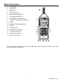
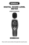
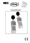
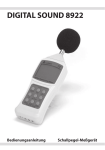
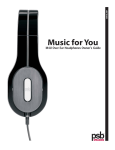
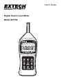
User's Guide
Digital Sound Level Meter
Model 407750
Introduction
Congratulations on your purchase of the Extech 407750. This device measures sound level in dB
and the measurement range can be set automatically or manually. The 407750 offers selectable
frequency weighting (‘A’ and ‘C’) and Time Response (Fast and Slow). The built-in RS-232 PC
interface allows the user to record readings onto a PC in real-time. Careful use of this meter will
provide years of reliable service.
Specifications
Display
Backlit 2000 count LCD with analog bargraph
Display update rate
Main LCD digits: 0.5 seconds; Bargraph: 50mS
Analog Bargraph
1dB steps with 50dB display range
Microphone
Electret condenser (0.5” diameter)
Measurement Bandwidth
31.5Hz to 8KHz
Measurement Range
A weighting: 30 to 130dB; C weighting: 35 to 130dB
6 ranges in 10 dB steps: 30 to 80dB, 40 to 90dB, 50 to
100dB, 60 to 110dB, 70 to 120dB, 80 to 130dB
Accuracy / Resolution
± 1.5dB / 0.1dB
Time response selections
Fast (125ms) and Slow (1 second)
AC and DC Analog outputs
0.707VAC rms at full scale; 10mVDC / dB;
3.5mm output jacks
Standards
Meets ANSI and IEC Type 2
External Calibrator
Extech models 407766 or 407744
Power
9V Battery; 20 hour battery life (typical) with low battery
indication
Dimensions/weight
3.2 x 10.1 x 1.5” (80 x 256 x 38mm) / 8.5 oz. (240g)
2
407750-EN v2.2 07/13
Meter Description
1.
LCD Display
2.
Microphone
3.
ON/OFF key
4.
REC (Record) key
5.
MAXHLD (Max Hold) key
6.
C/A Weighting Select key
7.
BA (Background Absorber) key
8.
F/S Fast / Slow Response select key
9.
DOWN
10. Backlit (LCD backlighting) key
11. UPPER
12. AC adaptor jack
13. Calibration screw adjust
14. AC analog output jack
15. DC analog output jack
16. RS-232 output jack
Note: The Battery Compartment and the Threaded Tripod mount access are located on the back
of the instrument (not pictured)
3
407750-EN v2.2 07/13
Operation
Quick Start
1. Power the meter by pressing the ON/OFF key.
2. The meter’s LCD will count down to zero (99.9, 88.8, 77.7, etc.) and then begin measuring
sound levels. If the LCD does not switch on after pressing the ON/KEY check the 9V battery.
3. Point the microphone toward the source of the sound level to be measured and view the reading
on the meter’s LCD.
‘A’ and ‘C’ Frequency Weighting
Select ‘A’ or ‘C’ weighting via the C/A key. The LCD will reflect the currently selected frequency
weighting. Use ‘A’ weighting to have the meter respond as the human ear would with regard to
frequency response (the human ear boosts and cuts amplitude over the frequency spectrum). ‘A’
weighting is used for environmental measurements, OSHA regulatory testing, law enforcement, and
workplace design. Select ‘C’ weighting for flat responding measurements (less amplitude boost or
cut across the frequency spectrum). ‘C’ weighting is used in applications where hearing
conservation is not an issue; for example, in the diagnosis of malfunctions in electrical, electronic
and mechanical devices.
FAST/SLOW Response Time
Select either FAST (125ms response) or SLOW (1 second response) measurements by pressing
the F/S key. The LCD will reflect the currently selected mode. Selection of ‘Fast’ or ‘Slow’ is
determined by the application and any directives or standards related to that application. For
example, most hearing conservation or OSHA related testing is done using SLOW and A weighting.
MAX HOLD
The meter is capable of taking continuous measurements and only updating the LCD when a higher
reading (than the one presently on the display) is detected. The bargraph display continues to
change while the main LCD waits for a higher reading. Press the MAXHLD key to activate the MAX
HOLD mode. The LCD will reflect the MAX HOLD function. Press the MAXHLD key again to return
to normal operation.
Record (REC) Function
To Record the Maximum and Minimum sound level measurements over a programmable period of
time, press the REC key. The REC indicator will appear on the LCD. Once the REC key is pressed,
the meter begins tracking the highest (MAX) and lowest (MIN) readings. Press the REC again and
the MIN indicator will appear on the LCD along with the lowest sound level reading since the REC
key was pressed. Press the REC again and the MAX indicator will appear along with the highest
reading the meter has encountered since the REC key was first pressed. Press and hold the REC
until the REC indicator extinguishes to exit the RECORD mode.
4
407750-EN v2.2 07/13
BA (Background Noise Absorber) Mode
The Background Noise Absorber allows the user to accurately measure equipment noise by
“eliminating” background noise. The Sound Level Meter first stores the background noise as a
reference level. From there, when a sound is measured, the display will show the sound level
measurement minus the background noise. To operate the meter in BA mode, follow these steps:
1. Power the meter.
2. Press the MAXHLD key (the MAX HOLD icon will appear on the LCD).
3. Press the BA key (‘F” will appear to the left of the SPL display icon).
4. Press the MAX HOLD key again (the MAX HOLD icon will reappear on the LCD).
5. The meter is now displaying the background, reference noise.
6. Power the device under test and note the new sound level meter reading.
7. If the reading changes, the new reading is the sound level of the device. If the reading does not
change, the noise produced from the device is either equal to or less than the background
noise.
8. Press the BA key again to return to the normal mode of operation.
Auto and Manual Ranging
The meter powers up in the Automatic Range mode. In automatic mode the meter automatically
finds the correct range in order to produce the best accuracy. However, if it is desired to set the
range manually, follow these steps:
1. Power the meter
2. Notice the two (2) digit number to the immediate left of the analog bargraph. This number is the
low end of the presently selected range (see the specifications for the ranges).
3. To change the range, press the UP key to raise the range or press the DOWN key to lower the
range. The two digit number on the left of the bargraph will change with each key-press.
4. An advantage of Manual mode is that it takes less time for the meter to take a reading. In Auto
Range mode the meter must first locate the correct range before displaying a measurement.
LCD Backlighting
Press the BACKLIT key to illuminate the LCD. The backlight will remain on for 5 seconds and then
automatically switch off to preserve battery life.
Auto Power Off
To preserve battery life, this meter has an automatic power off feature. If the unit is not used for
approximately 20 minutes, the meter shuts off. To override this function, follow these steps:
1. From a power OFF condition, press and hold the ON/OFF and MAX HOLD keys simultaneously.
2. When ‘n’ appears on the display, release the MAX HOLD and then the ON/OFF key.
3. The Auto Power Off feature is now disabled. Note that the Auto Power Off feature is re-activated
the next time the meter is powered down.
5
407750-EN v2.2 07/13
Analog Outputs
The meter includes an AC and a DC analog output. These outputs are proportional to the displayed
sound level and are ideal for use with chart recorders and dataloggers. The AC output is 0.707V
rms full scale and the DC output is 10mV per dB. The labeled 3.5mm output mini-plugs are located
on the bottom of the instrument.
RS-232 Output
The meter includes an RS-232 PC interface jack. This PC interface allows the meter to store and
display readings on a PC as they are recorded. The interface cable and software for data
acquisition are sold separately. Detailed instructions are provided with the software.
6
407750-EN v2.2 07/13
Reference Information
Frequency Weighting Characteristics
Frequency (Hz)
31.5
63
125
250
500
1k
2k
4k
8k
A Weighting
-39.4dB
-26.2dB
-16.1dB
-8.6dB
-3.2dB
0dB
+1.2dB
+1dB
-1.1dB
C Weighting
-3dB
-0.8dB
-0.2dB
0dB
0dB
0dB
-0.2dB
-0.8dB
-3dB
Tolerance (IEC 651 Type 2)
±3dB
±2dB
±1.5dB
±1.5dB
±1.5dB
±1.5dB
±2dB
±3dB
±5dB
Typical A-Weighted Sound Levels
dB
140
50HP Siren (100')
130
Jet takeoff (200')
120
Riveting machine
110
Chain saw
100
Subway (20')
90
Pneumatic drill (50')
80
Vacuum cleaner (10')
70
Large store
60
Small office
50
Night residential area
40
Whisper (5'0)
30
Boiler room
Freight train (100')
Speech (1')
Large Office
Residence
Sound studio
20
10
Threshold of hearing
0
7
407750-EN v2.2 07/13
Battery Replacement
When the low battery message appears on the LCD, the 9V battery has fallen to a critically low
voltage level and should be replaced as soon as possible. The battery compartment cover resides
at the rear of the meter. Remove the rear battery compartment screw and remove the battery
compartment cover, change the battery, and replace the compartment cover.
8
407750-EN v2.2 07/13
Warranty FLIR Systems, Inc. warrants this Extech Instruments brand device to be free of defects in parts and workmanship for one year from date of shipment (a six month limited warranty applies to sensors and cables). If it should become necessary to return the instrument for service during or beyond the warranty period, contact the Customer Service Department for authorization. Visit the website www.extech.com for contact information. A Return Authorization (RA) number must be issued before any product is returned. The sender is responsible for shipping charges, freight, insurance and proper packaging to prevent damage in transit. This warranty does not apply to defects resulting from action of the user such as misuse, improper wiring, operation outside of specification, improper maintenance or repair, or unauthorized modification. FLIR Systems, Inc. specifically disclaims any implied warranties or merchantability or fitness for a specific purpose and will not be liable for any direct, indirect, incidental or consequential damages. FLIR’s total liability is limited to repair or replacement of the product. The warranty set forth above is inclusive and no other warranty, whether written or oral, is expressed or implied. Calibration, Repair, and Customer Care Services FLIR Systems, Inc. offers repair and calibration services for the Extech Instruments products we sell. NIST certification for most products is also provided. Call the Customer Service Department for information on calibration services available for this product. Annual calibrations should be performed to verify meter performance and accuracy. Technical support and general customer service is also provided, refer to the contact information provided below. Support Lines: U.S. (877) 439‐8324; International: +1 (603) 324‐7800 Technical Support: Option 3; E‐mail: [email protected] Repair & Returns: Option 4; E‐mail: [email protected] Product specifications are subject to change without notice Please visit our website for the most up‐to‐date information www.extech.com FLIR Commercial Systems, Inc., 9 Townsend West, Nashua, NH 03063 USA ISO 9001 Certified Copyright © 2013 FLIR Systems, Inc. All rights reserved including the right of reproduction in whole or in part in any form www.extech.com 9
407750-EN v2.2 07/13