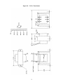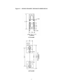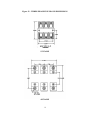
1
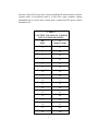
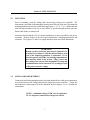
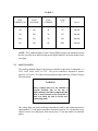
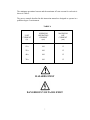
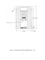
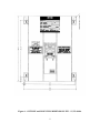
INSTALLATION, OPERATION and
MAINTENANCE MANUAL
MODEL ZF1, ZF2 and ZF3 rated 15, 25, 40 & 70 AMP
SINGLE and THREE PHASE - 2 or 3 LEG CONTROL
SOLIDSTATE RELAY (SSR) POWER CONTROLS
UL/cUL FILE NUMBER – E151547
CSA FILE NUMBER – LR91210
CE – See last page of manual for CE Declaration of Conformity.
AMETEK HDR POWER SYSTEMS
3563 INTERCHANGE ROAD
COLUMBUS, OHIO 43204
TEL: 614-308-5500
TOLL FREE: 1-888-PWR-CNTL (797-2685)
FAX: 614-308-5506
SCR Power Controls/Systems & Power Supplies
Dear Client:
On behalf of all of AMETEK HDR's employees, I want to take this opportunity to "thank you" for
purchasing an AMETEK HDR Power Systems' SCR Power Control.
We believe AMETEK HDR represents the best overall solution to your SCR Power Control needs in
the industry today. We do this by providing a quality manufactured reliable unit with fast, on-time
delivery and a competitive price.
All of our employees are dedicated to your success. If you have any questions, comments or
concerns, please call me toll free at 1-888-PWR-CNTL (797-2685).
Sincerely,
AMETEK HDR POWER SYSTEMS
George A. Sites
Vice President
GAS/be
3563 Interchange Road
Columbus, OH 43204-1400 USA Telephone: 614-308-5500 1-888-PWR-C NTL FAX: 614-308-5506
REVISION PAGE
Page
Change
28
1
Revision
Date
Added EMC statement to EC Declaration
11-00
NOTE: ALL SPECIFICATIONS SUBJECT TO CHANGE WITHOUT PRIOR NOTICE
COPYRIGHT 2003
AMETEK HDR POWER SYSTEMS
TABLE OF CONTENTS
Para.
Title
Page
Section 1 - DESCRIPTION
1-1
1-2
1-3
1-4
1-5
1-6
Models Covered...................................................................................................1
General Description..............................................................................................1
Applications .........................................................................................................1
Specifications.......................................................................................................1
Options ................................................................................................................2
Operation.............................................................................................................2
Section 2 - INSTALLATION
2-1
2-2
2-3
Mounting .............................................................................................................5
Line/Load Power Wiring ......................................................................................5
Safety Issues ........................................................................................................6
Section 3 - COMMAND SIGNAL CALIBRATION
3-1
3-2
3-3
3-4
Zero and Span Adjustments..................................................................................19
Command Indicator..............................................................................................19
Remote Manual Control.......................................................................................19
Process Command Signal .....................................................................................20
Section 4 - MAINTENANCE
4-1
4-2
4-3
Environmental Concerns ......................................................................................24
Line/Load Power Connections .............................................................................24
Troubleshooting Typical Symptoms .....................................................................24
Section 5 - SERVICE AND SPARE PARTS
5-1
5-2
5-3
Customer Service.................................................................................................26
Spare Parts...........................................................................................................26
Warranty..............................................................................................................26
i
TABLES and ILLUSTRATIONS LIST
TABLES
Table
1
2
3
4
Title
Page
Specifications............................................................................................................. 1
% Output Voltage at Various Input Command Levels ................................................ 3
Fusing Requirements.................................................................................................. 6
Minimum/Maximum Currents .................................................................................... 7
ILLUSTRATIONS
Figure
1
2
3
4
5
6
7
8
9
10
11
12
13
14
15
Title
Page
Line/Load Power Wiring ZF1 Models ........................................................................ 8
Line/Load Power Wiring ZF2 Models ........................................................................ 8
Line/Load Power Wiring ZF3 Models ........................................................................ 9
Outline & Mounting Dimensions – ZF1 15, 25 & 4 0A............................................. 10
Outline & Mounting Dimensions – ZF1 70A ............................................................ 11
Outline & Mounting Dimensions – ZF2 15, 25 & 40A ............................................. 12
Outline & Mounting Dimensions – ZF2 70A ............................................................ 13
Outline & Mounting Dimensions – ZF3 15, 25 and 40A ........................................... 14
Outline & Mounting Dimensions – ZF3 70A ............................................................ 15
24 VAC Transformer Dimensions & Schematic........................................................ 16
Single-Phase Fuse Block Dimensions ....................................................................... 17
Three-Phase Fuse Block Dimensions........................................................................ 18
Remote Manual Control (-V) Models....................................................................... 21
Process Command Signal (-V) Models..................................................................... 22
Process Command Signal (-C) Models ..................................................................... 23
ii
DRAWING LIST
Schematic, ZF1 15 Thru 40A (-C) ................................................................................. S2710000
Schematic, ZF1 15 Thru 40A (-V)................................................................................. S2710001
Schematic, ZF1 70A (-C) .............................................................................................. S2710079
Schematic, ZF1 70A (-V) .............................................................................................. S2710080
Schematic, ZF1-C Firing Circuit .................................................................................... S2078000
Assembly, ZF1-C Firing Circuit .................................................................................... M2078000
Schematic, ZF1-V Firing Circuit.................................................................................... S2079000
Assembly, ZF1-V Firing Circuit.................................................................................... M2079000
Schematic, ZF2 15 thru 40A (-C) .................................................................................. S2710017
Schematic, ZF2 15 thru 40A (-V) .................................................................................. S2710018
Schematic, ZF2 70A (-C) .............................................................................................. S2710081
Schematic, ZF2 70A (-V) .............................................................................................. S2710082
Schematic, ZF2-C Firing Circuit .................................................................................... S2081000
Assembly, ZF2-C Firing Circuit .................................................................................... M2081000
Schematic, ZF2-V Firing Circuit ................................................................................... S2082000
Assembly, ZF2-V Firing Circuit .................................................................................... M2082000
Schematic, ZF3 15 thru 40A.......................................................................................... S2710034
Schematic, ZF3 70A ..................................................................................................... S2710083
Schematic, ZF3 Firing Circuit........................................................................................ S2099148
Assembly, ZF3 Firing Circuit......................................................................................... M2099148
NOTE: If full size drawings are required, contact HDR inside sales and request the desired drawing(s)
by the drawing number listed above.
iii
Section 1 - DESCRIPTION
1-1
MODELS COVERED
This manual covers the ZF1, ZF2 and ZF3 models rated 15, 25, 40 & 70 amperes and
their options.
1-2
GENERAL DESCRIPTION
The ZF1, 2 and 3 models are solid-state, single and three-phase, zero-fired (ZF)
Solidstate Relay power controls which will operate on line voltages up to 600 VAC.
They accept most all standard process command signals and regulate the output voltage.
Zero and Span Multi-turn potentiometers are provided to ease calibration. An isolated
base Solid-State-Relay (SSR) module is used for power switching in each controlled
phase. This module contains two SCRs connected back to back and a zero-crossing
detector. The firing circuit is based on common integrated circuits that provides very
reliable operation. Terminals are provided to ease installation.
1-3
APPLICATIONS
A variable time base firing circuit is used to provide precise control of power to resistive
loads. These units should never be used on inductive loads. However, they are versatile
enough to be used in place of mechanical contactors and mercury relays on dryers, kilns,
ovens, environmental chambers, extruders, molding equipment, and other types of
equipment which uses resistive heat.
1-4
SPECIFICATIONS
TABLE 1
CONTROL METHOD - Zero firing of back to back SCRs in each phase.
VOLTAGE RATING - Up to 600 VAC, 1 or 3 Ph., 50/60 Hz.
CURRENT RATING - 15, 25, 40 & 70 Arms.
COMMAND SIGNAL - 4-20 ma, 0-5 VDC/0-10 VDC, Manual Control.
ISOLATION - 2500 Vrms from line/load to command signal to ground.
ADJUSTMENTS – Zero and Span, Multi-turn.
AMBIENT TEMPERATURE – Operating, 0 to 50C; Storage, -10 to 70C.
AGENCY LISTING – 15, 25, 40A UL/cUL Listed, CSA Certified, CE Compliant.
70A UL/cUL, CE Compliant
1
1-5
OPTIONS
Three options are available: a Fuse Kit, a 24 VAC Control Transformer for the -V
Models and heat sink thermostat(s).
The Fuse Kit (Option FK) consists of a Semi-Conductor Fuse and fuse block. It is the
user's responsibility to mount this fuse kit.
The (-V) models require 24 VAC (3VA) control power. An appropriately sized
transformer (Option TX) is available with 120, 240, 400, 480 or 575 VAC primaries.
Over-temperature thermostats are mounted on each heat sink. Specify NO for normally
open or NC for normally closed.
1-6
OPERATION
The power is controlled by the switching action of two SCRs connected in a back to
back configuration in each controlled phase. The zero crossing detector built into the
solid-state relay module synchronizes the gating of these SCRs with the line frequency
(either 50 or 60 HZ). The firing circuit provides timing pulses to the SSR proportional
to the command signal. These pulsed determine the output level. The output may be
adjusted by a voltage or current signal from a process controller. Zero and Span
controls allow the user to calibrate the power controller’s output to the process signal.
Terminals are also available for connection of a remote manual potentiometer on the (V) model.
WARNING
Hazardous voltages exist at the power controller
heat sinks and at the load at all times when the
input voltage is connected. This condition exists
even when the controller is set to deliver zero
output.
NOTE: On the (-V) models, the zero control
can be used as a manual control, or a remote
manual control can be connected.
The power controller regulates the output voltage by proportionally controlling the
number of AC cycles “on” versus the number “off”. Because the voltage is “turned
on” at zero crossing, very little radio frequency interference (RFI) is generated and
2
the power factor (PF) is near unity. Keep in mind that ZF units can only be used on
resistive loads. If an inductive load or a load with a large resistance change
(instantaneously or cold to hot) is being used, a phase fired (PF) power control
should be used.
TABLE 2
% OUTPUT VOLTAGE AT VARIOUS
INPUT COMMAND LEVELS
Ma
Input
%
Output Voltage
4
0
5
10
6
30
7
41
8
53
9
59
10
64
11
68
12
71
13
76
14
80
15
85
16
88
17
91
18
95
19
98
20
100
3
Table 2 shows the percent output voltage at various input command signal levels. The
variable time base firing circuit picks the minimum length time base to maintain as
constant a power level to the heating elements as possible. By doing this, thermal
shock and mechanical abuse to the heating elements is reduced and the life expectancy
of the element should increase.
NOTE: The percent output voltage for any given command signal
Is affected by the exact setting of the zero and span potentiometers.
Table 2 is to be used only as a reference.
4
Section 2 - INSTALLATION
2-1
MOUNTING
Prior to mounting, verify the voltage and current rating of the power controller. The
information is provided on the nameplate located on the left side of the unit. Determine the
mounting dimensions from the outline drawing Figures 3, 4, 5, 6, 7 or 8. Mount the unit
with line/load terminals to the top so that airflow is upward through the heat sink fins.
Ensure that airflow is unrestricted.
Mount the fuse kit and the 24 VAC control transformer as close as possible to the power
controller. Refer to Figure 10 for the control transformer’s mounting dimensions and
schematic. Use Figures 11 and 12 for single and three-phase fuse block dimensions.
WARNING
Branch circuit overcurrent protection is required to be
provided in accordance with the national and/or local
code of the inspecting authority or equivalent. If it is
desired to protect the SCRs, fast clearing semiconductor
fuses must be added to the system. Table 3 shows the
fuse voltage, fuse current, fuse maximum I2T rating and
conditional short circuit current (CSCA) rating for each
of the power control’s ratings.
2-2
LINE/LOAD POWER WIRING
Connect the line/load using appropriately sized and insulated wire/cable per any national or
local codes based on the voltage and current rating of the power controller. Torque the
line/load power connections to 25 in-lbs. minimum. Refer to Figures 1, 2 or 3 for all power
connections.
NOTE: a minimum rating of 75°C wire is required by
UL for all power connections to the power control.
5
TABLE 3
UNIT
CURRENT (A)
FUSE
VOLTAGE
FUSE
CURRENT
FUSE
I2 T
CSCA
15A
700
20
157
200,000
25A
700
30
427
200,000
40A
700
50
950
200,000
70A
700
80
4085
200,000
NOTE: The Conditional Short Circuit Current (CSCA) rating is the maximum current
the fuse can safely clear and this rating must be higher than the current the branch circuit
can supply.
2-3
SAFETY ISSUES
The rated operational voltage of each power controller is shown on it’s nameplate, i.e.
120V, 240V, 400V, 480V, or 575V. The power controller is designed to operate
between +10% and –15% of this rated operational voltage in an Over Voltage Category
III environment.
WARNING
Power control units are not suitable to
provide isolation due to the use of
semiconductors and other components that
allow a small current to flow from line to
load even when the unit is in the nonconducting mode.
The voltage drop across the switching semiconductor while in the conducting mode is
approximately 1.5 volts and is somewhat a function of current. To calculate the power
control’s power loss, multiply the load current times 1.5 time the number of controlled
phases.
6
The minimum operational current and the maximum off state current for each unit is
shown in Table 4.
The power controls described in this instruction manual are designed to operate in a
pollution degree 2 environment.
TABLE 4
UNIT
CURRENT
(A)
MINIMUM
OPERATING
CURRENT
(ma)
MAXIMUM
OFF
CURRENT
(ma)
15A
100
15
25A
100
15
40A
100
15
70A
100
15
HAZARDS EXIST
DANGEROUS VOLTAGES EXIST
7
Figure 1 – LINE/LOAD POWER WIRING ZF1 MODELS
Figure 2 – LINE/LOAD POWER WIRING ZF2 MODELS
8
Figure 3 – LINE/LOAD POWER WIRING ZF3 MODELS
Figure 4 - OUTLINE and MOUNTING DIMENSIONS ZF1 - 15, 25 & 40A
9
Figure 5 – OUTLINE and MOUNTING DIMENSIONS ZF1 – 70A
10
Figure 6 – OUTLINE and MOUNTING DIMENSIONS ZF2 – 15, 25 & 40A
11
Figure 7 – OUTLINE and MOUNTING DIMENSIONS ZF2 – 70A
12
Figure 8 – OUTLINE and MOUNTING DIMENSIONS ZF3 – 15, 25 & 40A
13
Figure 9 – OUTLINE and MOUNTING DIMENSIONS ZF3 – 70A
14
15
Figure 10 – 24 Vac Transformer
16
Figure 11 – SINGLE-PHASE FUSE BLOCK DIMENSIONS
15/25 AMP
40/70 AMP
17
Figure 12 – THREE-PHASE FUSE BLOCK DIMENSIONS
15/25 AMP
40/70 AMP
18
Section 3 - COMMAND SIGNAL CALIBRATION
3-1
ZERO AND SPAN ADJUSTMENTS
On (-V) models (voltage input) the Zero potentiometer has both positive and negative
voltages available making it usable as a manual or zero control. By turning the Zero
control clockwise the unit's output voltage will increase proportionally to the
adjustment. Turning it counter-clockwise will decrease the output, or zero the output
for a non-zero based command signal. Zero is mid rotation.
On (-C) models (4-20ma current input only) the Zero potentiometer has only the
negative voltage available and, therefore, can only be used for zeroing the output for a
4-20ma command signal. Because the power controller pulls it’s operating power from
the 4-20ma source, no other device can be series or parallel connected.
The Span potentiometer on both (-V) & (-C) models is used to adjust the maximum
output level. It will adjust for either a remote manual control or a command signal
input. Clockwise adjustment increases the output while counter-clockwise adjustment
decreases the output. Due to some interaction between controls, it may be necessary to
repeat both the zero and span adjustments.
3-2
COMMAND INDICATOR
The Command Indicator is a green Light Emitting Diode (LED) located between the
Zero and Span controls. The flash rate of this LED will vary in synchronization with the
output of the unit. The rate will be faster with higher outputs and slower with lower
outputs.
3-3
REMOTE MANUAL CONTROL (-V MODELS ONLY)
NOTE: A remote manual control cannot be used on a (-C) model.
Start with the Zero Control set approximately at mid rotation and the Span Control set
minimum (counter-clockwise). Connect a 5K ohm remote manual control as shown in
Figure 13. With the unit energized and the remote manual control fully counterclockwise, adjust the Zero Control until the unit is just off. Next turn the remote manual
control fully clockwise and adjust the Span Control until the desired output voltage is
reached. This procedure may have to be repeated since some interaction between the
Zero and Span Controls exist. The exact setting of the zero and span controls can affect
the linearity, so be as precise as possible.
19
3-4
PROCESS COMMAND SIGNAL
This procedure is similar to the Remote Manual Control procedure. Start with the Zero
Control set approximately at mid rotation and the Span Control set at minimum.
Connect the Command Signal with the (-) on terminal 1 and the (+) on terminal 2. Refer
to Figure 14 for (-V) Models, and to Figure 15 for (-C) Models. Then energize the unit.
With the Command Signal at minimum, adjust the Zero Control so the unit is just off
(zero output voltage); next, with the Command Signal at full output, adjust the Span
Control so the output voltage is at the desired output level. Repeating this procedure
may be necessary due to some interaction between the Zero and Span Controls.
NOTE: The (-V) models will accept a 0-5
VDC/0-10 VDC, 4-20 ma or a manual
control input. The (-C) model will only
accept a 4-20 ma input and cannot be
series or paralleled with other units.
20
Figure 13 - REMOTE MANUAL CONTROL (-V) MODELS
21
Figure 14 - PROCESS COMMAND SIGNAL (-V) MODELS
22
Figure 15 - PROCESS COMMAND SIGNAL (-C) MODELS
23
Section 4 - MAINTENANCE
4-1
ENVIRONMENTAL CONCERNS
Always verify that the power control is mounted in a clean, dust free environment. Clean
the heat sink(s) and printed circuit board periodically so no dust or dirt accumulates on
the unit. Dust or dirt on the heat sink fins can prevent proper airflow and heat dissipation
causing overheating of the semiconductors. Conductive dust or dirt can cause shorts or
arcing, which can cause damage to the unit.
WARNING
DISCONNECT ALL SOURCES OF POWER TO THE POWER CONTROLLER
PRIOR TO CLEANING. THE UNIT IS NOT SUITABLE FOR HOSE DOWN
CLEANING. USE VACUUM, BRUSH OR LOW PRESSURE AIR.
4-2
LINE/LOAD POWER CONNECTIONS
Periodically turn the power off to the ZF1 and check for corrosion and tightness of the
power connections. If any corrosion is evident, clean the cables and connectors and
reconnect them. Tighten them to 25 in-lbs.
4-3
TROUBLESHOOTING TYPICAL SYMPTOMS
Any one of the following problems can be repaired in the field. Any other problems
require returning the power controller to HDR for servicing.
1.
Symptom - No output.
Cause - Open fuse or no 24 VAC control power on (-V) Models.
Solution - Disconnect the input power and check the fuse, replace the fuse if
faulty. If the fuse checks ok, verify the 24 VAC control power on terminals 4 & 5
if the unit is a (-V) Model. If neither of these solve the problem, contact the
factory.
2.
Symptom - Full output regardless of command signal level.
Cause - Shorted SSR module or defective firing circuit.
Solution - Readjust the zero and span controls. If this does not help, disconnect
the input power and remove the firing circuit. Re-energize, if the output is on
full, replace the SSR module. If the output is off, then most likely the firing
circuit is defective. Consult the factory.
24
3.
Symptom - The unit is not variable from 0 to full output.
Cause - Defective firing circuit.
Solution - If neither of the first two symptom/solutions are the answer,
order a replacement firing circuit from the factory.
25
Section 5 - SERVICE AND SPARE PARTS
5-1
CUSTOMER SERVICE
If you have operational problems which cannot be resolved using this manual, please
contact the Service Department at AMETEK HDR. Our normal work hours are 8 a.m.
to 3:30 p.m., U.S.A. EASTERN TIME ZONE, Monday through Friday.
TELEPHONE: 1-888-PWR-CNTL (797-2685) OR 614-308-5500.
Our answering machine at 614-308-5500 will answer after hours and we will
return your call the next working day.
FAX: 614-308-5506. 24 hours per day automatic answering.
EMERGENCY: Pager 1-800-759-8888, PIN # 1245473.
5-2
SPARE PARTS
Inside Sales should be contacted for any spare parts order whether routine or
emergency during normal working hours. All after hours requirements should be called
in on our 614-308-5500 answering machine. Please have as much information available
as possible pertaining to the model number, serial number, AMETEK HDR order
number and parts required. A purchase order number should be available.
5-3
WARRANTY
AMETEK HDR warrants that the equipment delivered will be free from defects in
workmanship and material for a period of five years from the date of shipment.
AMETEK HDR will repair or replace, at AMETEK HDR's option, any part found
defective during proper and normal use, provided that written notice of the nature of
the defect is received by AMETEK HDR within the five year warranty period and that
the customer returns the part to AMETEK HDR freight paid both ways. This warranty
is not transferable by the initial end user.
AMETEK HDR MAKES NO OTHER WARRANTIES, EXPRESSED OR IMPLIED
(INCLUDING, WITHOUT LIMITATION, MERCHANTABILITY, FITNESS FOR
PURPOSE, OR AGAINST INFRINGEMENT OF ANY PATENT) EXCEPT AS
EXPRESSLY PROVIDED HEREIN.
26
THE REMEDY OF REPAIR OR REPLACEMENT IS CUSTOMER'S SOLE AND
EXCLUSIVE REMEDY AND WILL SATISFY ALL OF AMETEK HDR'S
LIABILITIES, WHETHER BASED ON CONTRACT, NEGLIGENCE, TORT,
PRODUCT LIABILITY, STRICT LIABILITY, OR OTHERWISE. IN NO EVENT
WILL HDR BE LIABLE FOR INCIDENT OR CONSEQUENTIAL DAMAGES,
NOR IN ANY EVENT SHALL HDR'S LIABILITY EXCEED THE UNIT PRICE OF
ANY DEFECTIVE PRODUCT OR PART.
27
EC DECLARATION OF CONFORMITY
WE:
AMETEK HDR POWER SYSTEMS
3563 Interchange Road
Columbus, Ohio 43204 - USA
Declare under our sole responsibility that the products listed below and bearing the CE label:
Type:
SCR power controllers with the following model designations and current ratings:
ZF1, ZF2, ZF3, PF1, PF3 - 15, 25, 40, 60, 70, 90,
120, 180, 225, 350, 500, 650, 800, 1000 and 1200A.
SHZF1, SHPF1 - 15, 30, 40, 60, 70, 90 and 120A
SHZF2, SHZF3, SHPF3 - 15, 25, 30, 60, 90, 120, 180 and 225A
SCZF1, SCPF1 - 15, 25, 40 and 65A
To which this declaration relates is in conformity with the technical requirements of the following
documents:
Title:
Low-voltage switchgear
and control gear
No.
Year:
IEC 947-5-1
1990-03
Low Voltage Directive
No.
Year:
IEC 73/23/EEC
1973-02
Degrees of protection provided
by enclosures (IP Code):
No.
Year:
IEC 529-2nd Edition
1989-11
Electromagnetic Compatibility
(EMC)
No.
IEC 89/336/EEC
Year: 1989-05
Warning
All phase-fired (PF) controllers will require line filters
and possibly shielded cables to meet the EMC
requirements.
(Environmental protection classification IP00 - for mounting inside an
enclosure)
Note:
Characteristics are according to manufactures specifications.
Name: George A. Sites
Title:
Vice President
Date:
November 9, 2000
Declaration written in accordance with I.S.O. – IEC/22 Guide.
28