1
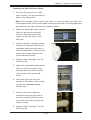
SUPER
SuperRack™
USER'S MANUAL
Revision 1.0
®
The information in this User’s Manual has been carefully reviewed and is believed to be accurate.
The vendor assumes no responsibility for any inaccuracies that may be contained in this document,
makes no commitment to update or to keep current the information in this manual, or to notify any
person or organization of the updates. Please Note: For the most up-to-date version of this
manual, please see our web site at www.supermicro.com.
Super Micro Computer, Inc. ("Supermicro") reserves the right to make changes to the product
described in this manual at any time and without notice. This product, including software and
documentation, is the property of Supermicro and/or its licensors, and is supplied only under a
license. Any use or reproduction of this product is not allowed, except as expressly permitted by
the terms of said license.
IN NO EVENT WILL SUPERMICRO BE LIABLE FOR DIRECT, INDIRECT, SPECIAL, INCIDENTAL,
SPECULATIVE OR CONSEQUENTIAL DAMAGES ARISING FROM THE USE OR INABILITY TO
USE THIS PRODUCT OR DOCUMENTATION, EVEN IF ADVISED OF THE POSSIBILITY OF
SUCH DAMAGES. IN PARTICULAR, SUPERMICRO SHALL NOT HAVE LIABILITY FOR ANY
HARDWARE, SOFTWARE, OR DATA STORED OR USED WITH THE PRODUCT, INCLUDING THE
COSTS OF REPAIRING, REPLACING, INTEGRATING, INSTALLING OR RECOVERING SUCH
HARDWARE, SOFTWARE, OR DATA.
Any disputes arising between manufacturer and customer shall be governed by the laws of Santa
Clara County in the State of California, USA. The State of California, County of Santa Clara shall
be the exclusive venue for the resolution of any such disputes. Super Micro's total liability for all
claims will not exceed the price paid for the hardware product.
FCC Statement: This equipment has been tested and found to comply with the limits for a Class
A digital device pursuant to Part 15 of the FCC Rules. These limits are designed to provide
reasonable protection against harmful interference when the equipment is operated in a commercial
environment. This equipment generates, uses, and can radiate radio frequency energy and, if not
installed and used in accordance with the manufacturer’s instruction manual, may cause harmful
interference with radio communications. Operation of this equipment in a residential area is likely
to cause harmful interference, in which case you will be required to correct the interference at your
own expense.
California Best Management Practices Regulations for Perchlorate Materials: This Perchlorate
warning applies only to products containing CR (Manganese Dioxide) Lithium coin cells. “Perchlorate
Material-special handling may apply. See www.dtsc.ca.gov/hazardouswaste/perchlorate”
WARNING: Handling of lead solder materials used in this
product may expose you to lead, a chemical known to
the State of California to cause birth defects and other
reproductive harm.
Manual Revision 1.0
Release Date: September 20, 2011
Unless you request and receive written permission from Super Micro Computer, Inc., you may not
copy any part of this document.
Information in this document is subject to change without notice. Other products and companies
referred to herein are trademarks or registered trademarks of their respective companies or mark
holders.
Copyright © 2011 by Super Micro Computer, Inc.
All rights reserved.
Printed in the United States of America
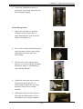
Preface
Preface
About This Manual
This manual is written for professional system integrators and PC technicians. It
provides information for the installation and use of the SuperRack™ system. Setup,
installation and maintainance should be performed by experienced technicians
only.
The SuperRack system is a high-end rack mount system that includes parts for
making different rack systems based upon any one of five standard models of the
SuperRack.
Manual Organization
Chapter 1: Introduction
The first chapter provides a overview of the SuperRack system and its various
models and components.
Chapter 2: SuperRack System Installation
This chapter describes the steps necessary to install the SuperRack system on site
and how to unship the SuperRack from its crate.
Chapter 3: Safety
You should thoroughly familiarize yourself with this chapter for a general overview
of safety precautions that should be followed when installing and servicing the
SuperRack.
Chapter 4: SuperRack Standard Models
This chapter provides detailed information about the features and elements of the
SuperRack system's standard models.
Appendix A: SuperRack System Specifications
This appendix contains specifications for the standard models of the SuperRack
system.
iii
SuperRack Installation Manual
Notes
iv
SuperRack Installation Manual
Table of Contents
Chapter 1 Introduction
1-1
Overview ......................................................................................................... 1-1
1-2
SuperRack Features ....................................................................................... 1-2
1-3
Returning Merchandise for Service................................................................. 1-2
1-4
Contacting Supermicro .................................................................................... 1-3
Chapter 2 System Safety
2-1
Electrical Safety Precautions .......................................................................... 2-1
2-2
General Safety Precautions ............................................................................ 2-2
2-3
ESD Precautions ............................................................................................. 2-3
2-4
Rack Precautions ............................................................................................ 2-4
Chapter 3 Rack Setup and Installation
3-1
Overview ......................................................................................................... 3-1
3-2
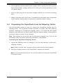
Inspecting the Rack and Shipping Crate ........................................................ 3-1
3-3
Preparing for Setup ......................................................................................... 3-1
Location Setup Recommendations ................................................................. 3-1
Rack Precautions ............................................................................................ 3-2
Server or Component Precautions.................................................................. 3-2
3-4
Unpacking the SuperRack from its Shipping Carton ...................................... 3-3
3-5
Installing EIA Mounting Posts ......................................................................... 3-7
Chapter 4 SuperRack Models
4-1
SuperRack Model SRK-42BF-01 ................................................................... 4-1
4-2
SuperRack Model SRK-42OR-01 .................................................................. 4-3
4-3
SuperRack Model SRK-42OR-02 .................................................................. 4-5
4-4
SuperRack Model SRK-42SE-01 ................................................................... 4-7
4-5
SuperRack Model SRK-42SE-02 ................................................................... 4-9
Chapter 5 Optional Accessories
5-1
Tools ................................................................................................................ 5-2
5-2
Accessories and Modification Procedures ...................................................... 5-3
Screw Bag ....................................................................................................... 5-2
Doors ............................................................................................................... 5-3
Top and Side Panels ....................................................................................... 5-6
Installing and Uninstalling Top Panels ....................................................... 5-8
Types of Top Panels ................................................................................... 5-9
Expansion Units ............................................................................................ 5-10
EIA Posts....................................................................................................... 5-12
Changing Casters ......................................................................................... 5-15
v
Table of Contents
Shelves and Slide Rails ................................................................................ 5-16
Component Installation ................................................................................. 5-18
Fan Modules ................................................................................................. 5-18
Cable Management Troughs and Fiber Optic Pipes .................................... 5-18
Mounting a Vertical Plate ......................................................................... 5-20
Mounting a Cable Management Trough to a Vertical Plate ..................... 5-21
Appendix A SuperRack System Parts List
vi
Chapter 1: Introduction
Chapter 1
Introduction
1-1
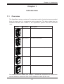
Overview
The SuperRack system consists of five standard models of racks that are assembled
from the same pool of components and accessories. The below table lists the
available standard rack models in the SuperRack system and their described
uses.
Picture
Rack Model
Description
SBK-42BF-01
42U Basic Frame system
SRK-42OR-01
42U Open Frame system
SRK-420R-02
42U Open Frame with Rear Expansion system
SRK-42SE-01
42U Enclosure system
SRK-42SE-02
42U Enclosure with Rear Expansion system
For details on these models see Chapter 4. Additional components or accessories
can be added or subtracted from these standard models by the user.
1-1
SuperRack Installation Manual
1-2
SuperRack Features
The SuperRack system offers the following features:
•
•
•
Supports quick release square mounting holes with adapters for round screw
mounts
User conventional cabling and cabling identification designs
Front, rear and side expansion units provide modular solutions for any system
configuration
•
Static load rating of 5511.55lbs (2500kg) to support high density rack components
•
EIA standard 310D hardware
•
Sturdy fully welded construction
•
Wide range of flexible accessory options
1-3
Returning Merchandise for Service
A receipt or copy of your invoice marked with the date of purchase is required
before any warranty service will be rendered. You can obtain service by calling your
vendor for a Returned Merchandise Authorization (RMA) number. When returning
to the manufacturer, the RMA number should be prominently displayed on the
outside of the shipping carton, and mailed prepaid or hand-carried. Shipping and
handling charges will be applied for all orders that must be mailed when service
is complete.
For faster service, RMA authorizations may be requested online at:
http://www. supermicro.com/support/rma/
Whenever possible, repack the chassis in the original Supermicro carton, using the
original packaging material. If these are no longer available, be sure to pack the
chassis securely, using packaging material to surround the chassis so that it does
not shift within the carton and become damaged during shipping.
This warranty only covers normal consumer use and does not cover damages
incurred in shipping or from failure due to the alteration, misuse, abuse or improper
maintenance of products. During the warranty period, contact your distributor first for
any product problems. The Supermicro warranty can be found on our website at:
http://www.supermicro.com/support/Warranty/
1-2
Chapter 1: Introduction
1-4
Contacting Supermicro
Headquarters
Address:
Super Micro Computer, Inc.
980 Rock Ave.
San Jose, CA 95131 U.S.A.
Tel:
+1 (408) 503-8000
Fax:
+1 (408) 503-8008
Email:
[email protected] (General Information)
[email protected] (Technical Support)
Web Site:
www.supermicro.com
Europe
Address:
Super Micro Computer B.V.
Het Sterrenbeeld 28, 5215 ML
's-Hertogenbosch, The Netherlands
Tel:
+31 (0) 73-6400390
Fax:
+31 (0) 73-6416525
Email:
[email protected] (General Information)
[email protected] (Technical Support)
[email protected] (Customer Support)
Asia-Pacific
Address:
Super Micro Computer, Inc.
4F, No. 232-1, Liancheng Rd.
Chung-Ho 235, Taipei County
Taiwan, R.O.C.
Tel:
+886-(2) 8226-3990
Fax:
+886-(2) 8226-3991
Web Site:
www.supermicro.com.tw
Technical Support:
Email:
[email protected]
Tel:
+886-(2) 8226-5990
1-3
SuperRack Installation Manual
Notes
1-4
Chapter 2: Safety
Chapter 2
System Safety
!
2-1
Warnings and Precautions!
!
Electrical Safety Precautions
!
Basic electrical safety precautions should be followed to protect yourself from harm
and the SuperRack system from damage:
•
•
•
•
•
•
•
Be aware of the locations of the power on/off switch on the chassis as well
as the room's emergency power-off switch, disconnection switch or electrical
outlet. If an electrical accident occurs, you can then quickly remove power from
the system.
Do not work alone when working with high voltage components.
Power should always be disconnected from the system when removing
or installing main system components, such as a server system. When
disconnecting power, you should first power down the operating system first
and then unplug the power cords.
When working around exposed electrical circuits, another person who is
familiar with the power-off controls should be nearby to switch off the power if
necessary.
Use only one hand when working with powered-on electrical equipment. This
is to avoid making a complete circuit, which will cause electrical shock. Use
extreme caution when using metal tools, which can easily damage any electrical
components or circuit boards they come into contact with.
Do not use mats designed to decrease static electrical discharge as protection
from electrical shock. Instead, use rubber mats that have been specifically
designed as electrical insulators.
The power supply power cords must include a grounding plug and must be
plugged into grounded electrical outlets.
2-1
SuperRack Installation Manual
•
2-2
This product may be connected to an power system. In all cases, make sure
that the unit is also reliably connected to Earth (ground).
General Safety Precautions
!
Follow these rules to ensure general safety:
•
•
•
•
•
•
Keep the area around the SuperRack system clean and free of clutter.
The SuperRack system weighs up to 258.91 lbs (117.44 kg) empty, and has a
shipping weight of up to 331.08 lbs (150.18 kg). The system should be moved
on its casters.
Place any system components and accessories that have been removed away
from the system or on a table so that they won't accidentally be stepped on.
While working on the system, do not wear loose clothing such as neckties and
unbuttoned shirt sleeves, which can come into contact with electrical circuits or
be pulled into a cooling fan.
Remove any jewelry or metal objects from your body, which are excellent metal
conductors that can create short circuits and harm you if they come into contact
with printed circuit boards or areas where power is present.
After accessing the inside of the system, close the system back up and secure
it after ensuring that all connections have been made.
2-2
Chapter 2: Safety
2-3
ESD Precautions
!
Electrostatic discharge (ESD) is generated by two objects with different electrical
charges coming into contact with each other. An electrical discharge is created to
neutralize this difference, which can damage electronic components and printed
circuit boards. The following measures are generally sufficient to neutralize this
difference before contact is made to protect your equipment from ESD:
•
•
•
•
•
•
•
•
Use a grounded wrist strap designed to prevent static discharge.
Keep all components and printed circuit boards (PCBs) in their antistatic bags
until ready for use.
Touch a grounded metal object before removing the board from the antistatic
bag.
Do not let components or PCBs come into contact with your clothing, which may
retain a charge even if you are wearing a wrist strap.
Handle a board by its edges only; do not touch its components, peripheral chips,
memory modules or contacts.
When handling chips or modules, avoid touching their pins.
Put the serverboard and peripherals back into their antistatic bags when not
in use.
For grounding purposes, make sure your computer chassis provides excellent
conductivity between the power supply, the case, the mounting fasteners and
the serverboard.
2-3
SuperRack Installation Manual
2-4
Rack Precautions
!
Warning: To reduce the risk of personal injury or damage to the equipment, do not
attempt to move large equipment racks alone. Obtain adequate assistance to stabilize
the rack during movement or hire professional equipment riggers to move it.
Make sure to follow the below rack precautions:
•
Ensure that the leveling jacks on the bottom of the rack are fully extended to
the floor with the full weight of the rack resting on them when the SuperRack
is setup in its location.
Caution: To reduce the risk of damage to the casters make sure that the full
weight of the rack rests on the leveling feet, and not on the casters. The casters
are designed only as an aid in moving the rack into position and are not designed
to support the weight of the rack, and may become damaged if relied upon to
support the rack.
•
•
•
In single rack installation, stabilizers should be attached to the rack. In multiple
rack installations, the racks should be coupled together.
Always make sure the rack is stable before extending a component from the
rack.
You should extend only one component at a time – extending two or more
simultaneously may cause the rack to become unstable.
2-4
Chapter 3: Rack Setup and Installation
Chapter 3
Rack Setup and Installation
3-1
Overview
This chapter provides information on setting up and installing your SuperRack
system. It is assumed in this chapter that your SuperRack system is shipped
assembled and ready for installation on site. .
3-2
Inspecting the Rack and Shipping Crate
You should inspect the crate the SuperRack system was shipped in and note if it
was damaged in any way. After unshipping the SuperRack from the crate inspect
the SuperRack itself for any damage. If the rack itself shows damage you should
file a damage claim with the carrier who delivered it.
3-3
Preparing for Setup
Before setting up your SuperRack system, please review the following setup
information and considerations for the location where the SuperRack system will
be installed.
Location Setup Recommendations
Below are recommended requirements for the setup location:
•
•
•
•
•
Location should have reliable local power and the utility should have the
availability to provide two alternate electrical feeds preferably from separate
sources
Have a minimum of two routes for data and phone infrastructure into the
building
Minimum one hour fire rated walls
Minimum 100+ PSF floor loading, or 200+ PSF floor loading to be determined
by equipment load
Nine (9) feet raised floor to ceiling clear height minimum
3-1
SuperRack Installation Manual
•
No exterior windows
•
No overhead water pipes
•
Power and Data cabling shall be in separate raceways overhead.
Rack Precautions
Equipment should be mounted into a rack so that a hazardous conditions do not
arise due to uneven mechanical loading.
Observe the following rack precautions
•
•
•
•
•
•
Leave enough clearance in front of the rack to enable you to open the front
door completely (~25-inches).
Allow approximately 30-inches of clearance in the back of the rack to allow for
sufficient airflow and ease in servicing.
Ensure that the leveling jacks on the bottom of the rack are fully extended to
the floor, with the full weight of the rack resting upon them.
In single rack installation, stabilizers should be attached to the rack. In multiple
rack installations, the racks should be coupled together.
Always make sure the rack is stable before extending a component from the
rack.
You should extend only one component at a time – extending two or more
simultaneously may cause the rack to become unstable.
Server or Component Precautions
Below are server and component precautions to observe for all components installed
in the SuperRack system:
•
•
•
Review the electrical and general safety precautions in Chapter 2.
Determine the placement of each component in the rack before you install the
rails.
Install the heaviest server components on the bottom of the rack first, and then
work up.
3-2
Chapter 3: Rack Setup and Installation
•
•
•
3-4
Use a regulating uninterruptible power supply (UPS) to protect the rack's servers
from power surges, voltage spikes and to keep your system operating in case
of a power failure.
Allow any hot plug drives and power supply modules to cool before touching
them.
Always keep the rack's front door (if installed) and all panels and components
on the servers closed when not servicing to maintain proper cooling.
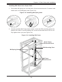
Unpacking the SuperRack from its Shipping Carton
Use the procedure below to help you unpack the SuperRack system from its
shipping carton. The SuperRack comes mounted on a pallet with steel retaining
brackets, packaged in a cardboard shipping carton. It is reinforced with plastic
strapping, and with both an interior plastic bag and exterior plastic covering that is
secured by tape to protect it from damage.
Note: The drawing for this section are for illustration purposes only. They do not
necessarily reflect the exact product(s) described in this manual.
Unpacking the SuperRack Shipping Carton
1. Inspect the shipping carton for damage. If you see any damage, contact your
shipping company.
Note: Make sure the crate is upright with the label arrow pointing upward.
2. Move the shipping carton to the SuperRack's deployment location.
Note: It is recommended that you use a lift or forklift for moving the SuperRack
to its final location.
3-3
SuperRack Installation Manual
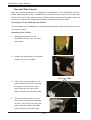
3. Remove the outer plastic wrapping from the carton, then cut and remove the
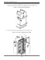
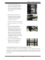
retaining straps from the outside of the shipping carton (see Figure 3-1).
Figure 3-1. Remove Retaining Straps
4. Remove the sides from the shipping carton (see Figure 3-2).
Figure 3-2. Remove Shipping Carton Sides
3-4
Chapter 3: Rack Setup and Installation
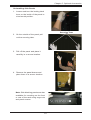
5. Cut the retaining tape from the carton and the interior plastic covering and
remove the remaining corners of the shipping carton from the outside of the
SuperRack (see Figure 3-3).
Figure 3-3. Remove Plastic Covering and Carton Corners
6. Remove all the remaining tape from the shipping carton pieces and the
interior plastic covering.
Note: The shipping carton can be reused for reshipping the SuperRack in the
future. It is recommended that you retain the carton pieces and the interior plastic
covering for any possible future use.
7. Inspect the SuperRack for any damage.
3-5
SuperRack Installation Manual
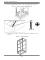
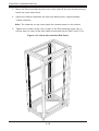
8. Remove the pallet retaining brackets with a screwdriver (see Figure 3-4).
Figure 3-4. Remove Pallet Retaining Brackets
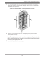
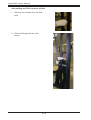
9. Gently take the SuperRack off its pallet and place it in its final location (see
Figure 3-5).
Figure 3-5. Rack Unpacked
3-6
Chapter 3: Rack Setup and Installation
3-5
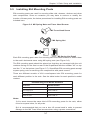
Installing EIA Mounting Posts
EIA mounting posts are used for securing slide rails, drawers, shelves and other
rack components. Since on occasion you may have to remove or modify the
location of these posts, the below procedures for installing EIA mounting posts are
included here.
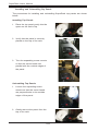
Figure 3-6. M6 Spring Nuts and Truss Head Screws
M6 Truss Head Screw
M6 Spring Nut
M6 Spring Nut Detail
Each EIA mounting post uses four securing M6 truss head screws to attach them
to the rack's horizontal struts using M6 spring nuts (see Figure 3-6).
The EIA mounting posts should be placed so that they are arranged with the unit
numbers facing out the front or rear of the SuperRack with the number "42" on top
and the "1" on the bottom (see Figure 3-7). SuperRack EIA mounting posts accept
square spring nuts for securing rack components with panel screws.
There are different models of 42U round/square hole EIA mounting posts for
each different position in the rack. See the table below for each position's model
number.
EIA Mounting Post Model Numbers
Position
Model Number
Front-left post
SRK-42PM-01
Front-right post
SRK-42PM-02
Rear-right post
SRK-42PM-11
Rear-left post
SRK-42PM-12
Notes:
1) You must choose the same kind of EIA mounting posts for the rack, either
round or square holes, for all posts.
2) It is recommended that you use a size H3 screw head in order to prevent
damage to the M6 Truss Head screws when using a power screwdriver.
3-7
SuperRack Installation Manual
Figure 3-7. EIA Post Numbering
42
42
41
41
Number "42" at
Top of Rack
3-8
Chapter 3: Rack Setup and Installation
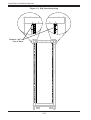
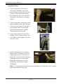
Installing EIA Posts into a Super Rack
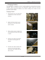
1. Push each M6 spring nut into the back of the horizontal strut's C-channel and
rotate each nut 90-degrees (see Figure 3-8).
Figure 3-8. Installing M6 Spring Nuts
2. Use the provided M6 Truss Head screws to lock the EIA mounting posts into
position into each of the M6 spring nuts on the horiznontal struts, but do not
fully tighten them yet (see Figure 3-9).
Figure 3-9. Installing EIA Posts
Rack Frame
Horizontal Strut
EIA Mounting Post
M6 Spring Nuts
M6 Truss
Head Screws
3-9
SuperRack Installation Manual
3. Move the EIA posts that face the front of the rack all the way forward till they
touch the outer frame front.
4. Adjust the distance between the front and back posts to approximately
742mm distance.
Note: The distance on top must match the measurement on the bottom.
5. Tighten the screws on the rear of each of the EIA mounting posts fully to
secure them to each of the rack frame's horizontal struts (see Figure 3-10).
Figure 3-10. Rack with Installed EIA Posts
3-10
Chapter 4: SuperRack Models
Chapter 4
SuperRack Models
4-1
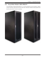
SuperRack Model SRK-42BF-01
The SuperRack Model SRK-42BF-01 is a 42U basic frame rack with no casters,
enclosure, rear expansion or front door.
4-1
SuperRack Installation Manual
SuperRack Model SRK-42BF-01 Specifications:
Net Weight
52.26 kg / 117.41 lbs
Maximum Height
2020.00 mm / 79.52 in
Maximum Width
598.00 mm / 23.54 in
Maximum Depth
950.00 mm / 37.40 in
Net Depth with Stabilizing Feet
950.00 mm / 37.40 in
Shipping Weight
80.72 kg / 177.95 lbs
Shipping Height
2170.00 mm / 85.43 in
Shipping Width
640.00 mm / 25.19 in
Shipping Depth
1030.00 mm / 40.55 in
Weight Capacity (Static Load)
2500.00 kg / 5511.55 lbs
Weight Capcity (Dynamic Load)
1250.00 kg / 2755.77 lbs
Minimum Mounting Depth
100.00 mm / 3.93 in
Maximum Mounting Depth
850.00 mm / 33.46 in
Rack Height
42 U
Color
Black
Units per Pallet
1
Vertical Posts
16 Gauge
Front Door
NA
Rear Door
NA
Roof
NA
EIA Mounting Rails
14 Gauge
Side Panels
NA
Conformance:
Regulatory Approvals
EIA-310-D
Standard Warranty
3 Years
Standards
UL 60950
Environmental Compliance
RoHS
4-2
Chapter 4: SuperRack Models
4-2
SuperRack Model SRK-42OR-01
The SuperRack Model SRK-42OR-01 is a 42U open frame rack with casters and
stands. This model does not come with an enclosure, rear expansion or front
door.
4-3
SuperRack Installation Manual
SuperRack Model SRK-42OR-01 Specifications:
Net Weight
55.42 kg / 122.18 lbs
Maximum Height
2092.70 mm / 82.38 in
Maximum Width
598.00 mm / 23.54 in
Maximum Depth
950.00 mm / 37.40 in
Net Depth with Stabilizing Feet
950.00 mm / 37.40 in
Shipping Weight
83.23 kg / 183.74 lbs
Shipping Height
2230.00 mm / 87.79 in
Shipping Width
640.00 mm / 25.19 in
Shipping Depth
1030.00 mm / 40.55 in
Weight Capacity (Static Load)
2500.00 kg / 5511.55 lbs
Weight Capcity (Dynamic Load)
1250.00 kg / 2755.77 lbs
Minimum Mounting Depth
100.00 mm / 3.93 in
Maximum Mounting Depth
850.00 mm / 33.46 in
Rack Height
42 U
Color
Black
Units per Pallet
1
Vertical Posts
16 Gauge
Front Door
NA
Rear Door
NA
Roof
NA
EIA Mounting Rails
14 Gauge
Side Panels
NA
Conformance:
Regulatory Approvals
EIA-310-D
Standard Warranty
3 Years
Standards
UL 60950
Environmental Compliance
RoHS
4-4
Chapter 4: SuperRack Models
4-3
SuperRack Model SRK-42OR-02
The SuperRack Model SRK-42OR-02 is a 42U open frame rack with casters and
stands and a rear expansion for power strips and cable runs. This model does not
come with an enclosure or front door.
4-5
SuperRack Installation Manual
SuperRack Model SRK-42OR-02 Specifications:
Net Weight
78.82 kg / 173.76 lbs
Maximum Height
2092.70 mm / 82.38 in
Maximum Width
598.00 mm / 23.54 in
Maximum Depth
1175.00 mm / 46.25 in
Net Depth with Stabilizing Feet
1175.00 mm / 46.25 in
Shipping Weight
111.56 kg / 245.94 lbs
Shipping Height
2230.00 mm / 87.79 in
Shipping Width
640.00 mm / 25.19 in
Shipping Depth
1260.00 mm / 49.60 in
Weight Capacity (Static Load)
2500.00 kg / 5511.55 lbs
Weight Capcity (Dynamic Load)
1250.00 kg / 2755.77 lbs
Minimum Mounting Depth
100.00 mm / 3.93 in
Maximum Mounting Depth
850.00 mm / 33.46 in
Rack Height
42 U
Color
Black
Units per Pallet
1
Vertical Posts
16 Gauge
Front Door
NA
Rear Door
NA
Roof
NA
EIA Mounting Rails
14 Gauge
Side Panels
NA
Conformance:
Regulatory Approvals
EIA-310-D
Standard Warranty
3 Years
Standards
UL 60950
Environmental Compliance
RoHS
4-6
Chapter 4: SuperRack Models
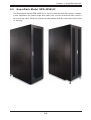
4-4
SuperRack Model SRK-42SE-01
The SuperRack Model SRK-42SE-01 is a 42U enclosed rack with casters, stands
and an enclosure with both front and rear door. Both the enclosure side panels and
the front door have locks for security.
4-7
SuperRack Installation Manual
SuperRack Model Model SRK-42SE-01 Specifications:
Net Weight
94.04 kg / 207.60 lbs
Maximum Height
2092.70 mm / 82.38 in
Maximum Width
598.00 mm / 23.54 in
Maximum Depth
1000.00 mm / 39.37 in
Net Depth with Stabilizing Feet
1000.00 mm / 39.37 in
Shipping Weight
121.85 kg / 268.63 lbs
Shipping Height
2230.00 mm / 87.79 in
Shipping Width
640.00 mm / 25.19 in
Shipping Depth
1030.00 mm / 40.55 in
Weight Capacity (Static Load)
2500.00 kg / 5511.55 lbs
Weight Capcity (Dynamic Load)
1250.00 kg / 2755.77 lbs
Minimum Mounting Depth
100.00 mm / 3.93 in
Maximum Mounting Depth
850.00 mm / 33.46 in
Rack Height
42 U
Color
Black
Units per Pallet
1
Vertical Posts
16 Gauge
Front Door
18 Gauge
Rear Door
18 Gauge
Roof
NA
EIA Mounting Rails
14 Gauge
Side Panels
18 Gauge
Conformance:
Regulatory Approvals
EIA-310-D
Standard Warranty
3 Years
Standards
UL 60950
Environmental Compliance
RoHS
4-8
Chapter 4: SuperRack Models
4-5
SuperRack Model SRK-42SE-02
The SuperRack Model SRK-42SE-02 is a 42U enclosed rack with casters, stands,
a rear expansion for power strips and cable runs, and an enclosure with a both a
front and rear door. Both the enclosure side panels and the front door have locks
for security.
4-9
SuperRack Installation Manual
SuperRack Model Model SRK-42SE-02 Specifications:
Net Weight
117.44 kg / 258.91 lbs
Maximum Height
2092.70 mm / 82.38 in
Maximum Width
598.00 mm / 23.54 in
Maximum Depth
1225.00 mm / 48.22 in
Net Depth with Stabilizing Feet
1225.00 mm / 48.22 in
Shipping Weight
150.18 kg / 331.08 lbs
Shipping Height
2230.00 mm / 87.79 in
Shipping Width
640.00 mm / 25.19 in
Shipping Depth
1260.00 mm / 49.60 in
Weight Capacity (Static Load)
2500.00 kg / 5511.55 lbs
Weight Capcity (Dynamic Load)
1250.00 kg / 2755.77 lbs
Minimum Mounting Depth
100.00 mm / 3.93 in
Maximum Mounting Depth
850.00 mm / 33.46 in
Rack Height
42 U
Color
Black
Units per Pallet
1
Vertical Posts
16 Gauge
Front Door
18 Gauge
Rear Door
18 Gauge
Roof
NA
EIA Mounting Rails
14 Gauge
Side Panels
18 Gauge
Conformance:
Regulatory Approvals
EIA-310-D
Standard Warranty
3 Years
Standards
UL 60950
Environmental Compliance
RoHS
4-10
Chapter 5: Optional Accessories
Chapter 5
Optional Accessories
This chapter covers information about various optional accessories that may be
included in your SuperRack system. See your enclosed parts list for a complete
list of parts supplied for your SuperRack system.
For the most recent list of parts and accessories available for the SuperRack system,
visit the Supermicro website at www.Supermicro.com for more details.
Some of the optional accessories available for your SuperRack system include
the following:
•
Fan modules for vented doors and top panel over fans
•
Doors for the front or rear
•
Top and side panels
•
Cable management troughs and Goose Neck pipes for fiber optic cables
•
Expansion units for front, rear or sides
•
Shelves
For a full list of SuperRack components, accessories and parts see Appendix A
for details.
5-1
SuperRack User's Manual
5-1
Tools
For modifying accessories on the SuperRack, you will need to use the following
required tools:
•
Phillips Screwdriver
•
Level
•
Box Cutter or shears
•
Tape Measure
•
Step Ladder
•
Set of Allen Wrenches
The following tools are optional, but recommended:
•
Flashlight
•
Gloves
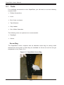
Screw Bag
The SuperRack comes complete with an attached screw bag for storing small
attachments and screws so that they are available for future use and do not get
misplaced or lost (Figure 5-1).
Figure 5-1: SuperRack Screw Bag
5-2
Chapter 5: Optional Accessories
5-2
Accessories and Modification Procedures
The following section contains descriptions of common accessories for the
SuperRack system and common procedures for modifying your SuperRack to
customize it for your use.
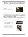
Doors
Several models of doors (solid, ventilated, mesh and filter) are available for mounting
in the SuperRack system either as front or rear doors. Ventilated mesh doors and
filter doors that provide for increased air flow can have fan modules installed on
them. The doors come with locking handles for added security. See Figure 5-1 for
an illustration of the parts used for mounting doors.
The procedures for uninstalling and installing the doors are shown below.
Figure 5-1: Door Mounting
Latch
Door
Hinge Pin
Hinge
5-3
SuperRack User's Manual
Installing Doors
1. If your rack does not already
have them installed, screw the
door latches to either the top and
bottom of the SuperRack frame
(for double doors), or to the midleft side of the frame (for single
doors).
2. If your rack does not already have
them installed, screw door hinges
onto your rack sides. For single
doors attach three on the right
side. For double doors attach
three hinges to both sides.
3. Lift and place the door onto the
hinges. For two doors setups, lift
and attach to the hinges only one
door at a time.
4. While holding the door in place,
aligned with its hinges, insert the
hinge pins to secure the door in
place. It is recommended that you
place the first pin in the middle
hinge and then place the pins
for the top and bottom hinges
afterwards.
Note: It is recommended that you have assistance to hold the door in place
while inserting the hinge pins.
5-4
Chapter 5: Optional Accessories
5. Close the SuperRack doors to
verify that they latch and move on
their hinges properly.
Uninstalling Doors
1. Open door(s) wide for access.
Unattach any fan modules or
other attachments from the door
before uninstalling it.
2. Pull out the hinge pins holding the
door in place one at a time while
stabilizing the door with your
other hand.
3. Lift the door off its hinges and
place it in a safe location till either
packing it away or reinstalling it
onto the SuperRack.
4. (Optional) Unscrew and remove
hinges and place them in a
secure place with their securing
screws if they are no longer
needed.
5. (Optional) Remove door latches
from the top and bottom of the
SuperRack if no longer needed.
5-5
SuperRack User's Manual
Top and Side Panels
Both top and side panels are available for installation in the SuperRack system.
Some panel models come ventilated for increased airflow, and some come with
locks for security. Side panels are secured by braces and securing tabs, while top
panels are secured by straight-head plastic expanding screw-mounts.
Installing and Uninstalling Side Panels
The procedures for installing and uninstalling SuperRack side panels (two per side)
are shown below.
Installing Side Panels
1. Attach panel braces to the
SuperRack frame, four for each
side panel.
2. Attach the side panel to the panel
braces to hold it in place.
Securing Tabs
3. Pull in the securing tabs on the
panel and gently push the panel
into place on the frame, then
when the panel is securely in
place, release the securing tabs.
4. Turn the locking latch lever on
the inside of the panel vertically
to lock it into place, securing the
panel with the frame, and then
screw its securing screw tight.
5-6
Chapter 5: Optional Accessories
Uninstalling Side Panels
1. Loosen and turn the locking latch
lever on the inside of the panel to
a horizontal position.
Securing Tabs
2. On the outside of the panel pull
out the securing tabs.
3. Pull off the panel and place it
carefully in a secure location.
4. Remove the panel braces and
place them in a secure location.
Note: Side blanking panels are also
available for mounting on the front
or rear of the rack using cage nuts
and panel screws.
5-7
SuperRack User's Manual
Installing and Uninstalling Top Panels
The procedures for installing and uninstalling SuperRack top panels are shown
below.
Installing Top Panels
1. Place the top panel gently into the
space on the rack's top.
2. Verify that the panel is securely
placed on the top of the rack.
3. Turn the expanding screw mounts
so that the screw heads are
parallel with the outside edges of
the panel.
Uninstalling Top Panels
1. Loosen the expanding screw
mounts so that the screw heads
are perpendicular to the outside
edges of the panel.
2. Gently remove the panel from the
top of the rack.
5-8
Chapter 5: Optional Accessories
Types of Top Panels
Top panels come in the following four categories.
Blanking Panels
Blanking panels are used to cover a
space in the top of the rack. They come
in sizes from 1U to 16U and come in
both solid and mesh panels.
Top Panel Fans
Top panel fans are different optional
fan panels that are built into top panels
and come in sizes from 3U to 14U in
size. These fan panels should have
cable troughs to cover their power
wiring.
Top Panel Openings
The top panel openings are different
optional top panels that contain two
openings, sealed by a rubber grommet,
that can each be used for a Goose
Neck pipe or allow openings from the
top down into the rack for wiring or
other uses.
Top Cable Management
Troughs
Three sizes of top cable management
troughs are available from 1U to 3U
to cover and handle wiring on the top
of the rack.
5-9
Goose Neck Pipe
SuperRack User's Manual
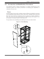
Expansion Units
There are several models of expansion units, ranging in width from 75mm to 300mm,
available for the SuperRack system that can be mounted on the front, sides or rear
of the rack for holding doors, cable troughs, power surge protectors panels and fans.
Two of the base SuperRack models come standard with rear expansion units. See
Figure 5-2 for an example of an expansion unit and its parts.
Figure 5-2: Expansion Unit and its Parts
Side Panel
Thumb Screw
Expansion Unit
Floor Levelers
5-10
Chapter 5: Optional Accessories
Installing an Extension Unit onto a Rack
1. Extend the rack extension's floor
levers and carefully mount the
extension unit flush to the rack.
Note: You may have to adjust the
floor levelers so that the retaining
screw holes in the rack extension
match up with the screw holes in
the rack itself.
2. Place and hand tighten the
retaining screws on the inside of
the extension unit's sides, bottom
and top to secure the extension
unit to the rack.
3. Tighten the retaining screws after
determining that the extension is
aligned correctly with the rack.
Uninstalling a Rack Extension from a Rack
To uninstall a rack extension, follow the previous procedure for installing a rack
extension in reverse by first unscrewing the securing screws, and then unmounting
the rack extension from the rack.
5-11
SuperRack User's Manual
Installing Rack Extension Side Panels
1. Mount the side panel to the side
of the rack extension on the rack
extension's side brackets.
Side Brackets
2. Screw in the retaining screws to
secure the rack extension side
panel in place.
Uninstalling Rack Extension Side Panels
To uninstall a rack extension side panel, follow the previous procedure in reverse
by first unscrewing its retaining screws, and then unmounting the side panel from
the rack extension's side brackets.
EIA Posts
EIA posts are mounting posts for securing slide rails, drawers, shelves and other
rack components. Since on occasion you may have to remove or modify the location
of these posts, the below procedures for installing and uninstalling EIA posts are
included here.
Each EIA post has four securing screws that attach to spring mounted screw holes
on the rack's horizontal struts. The posts should be placed so that they are arranged
with the unit numbers facing out the front or rear of the SuperRack with the number
"42" on top and the "1" on the bottom. SuperRack EIA posts accept square cage
nuts for securing rack components with panel screws.
5-12
Chapter 5: Optional Accessories
Installing an EIA Post into a Rack
1. Put the right front post on right
side of frame. The post should be
flush to the frame front.
Note: The numbers should be on the inside of the post when you place the
correct post on the correct side. Make sure the proper post is on the proper side
and that both the right and left post numbers match.
2. Match the adjustable spring screw
holes on the rack's horizontal
struts so that the screw holes
match up with the holes in the
EIA post.
3. Screw in the four retaining screws
through the EIA post and into the
adjustable spring screw holes on
the horizontal struts. Start with the
center two screws and then the
top and bottom screws.
4. Repeat steps 1 through 3 for the
left front post.
5. Adjust the adjustable spring screw
holes for the rear posts so that
they all match up with the same
rules on the rack's horizontal
struts.
6. Place the right rear post into
position in the rack so that it lines
up with the adjustable spring
screw holes.
7. Screw in the three retaining
screws for the right rear post to
secure it, starting with the center
two screws and then the top and
bottom screws.
8. Repeat steps 5 through 7 for the
left front post.
5-13
SuperRack User's Manual
Uninstalling an EIA Post from a Rack
1. Remove the screws from the EIA
post.
2. Pull the EIA post off the rack
frame.
5-14
Chapter 5: Optional Accessories
Changing Casters
The SuperRack is mounted on four 3" swivel casters for moving the rack when
required. When not being moved, the SuperRack system should be mounted
on floor levelers instead for stability. If you need to change out a caster, use the
procedure shown below.
Changing Casters
1. Tip the rack over on its side onto
a platform so it does not touch
the floor.
2. Adjust the floor levelers up so
they are out of the way of the
swivel casters.
3. With an Allen wrench, detach the
screws that secure the first caster
in place.
4. Remove the caster and inspect
the caster mounting plate for
defects.
5. Put the new caster in place and
screw in the securing screws
around the new caster with the
Allen wrench.
5-15
SuperRack User's Manual
Note: There are two sets of screw holes used for mounting casters. The inner
set is for smaller 2.5" casters, while the outer set is for 3" casters. User this outer
set for SuperRack 3" casters.
Note: Double-check that all screws have lock washers on them and that they
are securely tightened before placing the SuperRack upright.
6. Redeploy the leveling stands so
that they are all back at the same
level.
7. Push the SuperRack back upright.
Shelves and Slide Rails
Various types of shelves for rack components are available for the SuperRack
system. They come in sizes from 1U-3U in height and are available as vented or
non-vented shelves. All shelves can be mounted with four cage nuts and four panel
screws onto the front EIA posts of the SuperRack.
The SuperRack also has 1U and 2U brackets with cable management troughs that
can mounted to EIA rails for supporting rack components. Use the procedures below
for installing and uninstalling this bracket system.
Installing Brackets with a Cable Management Trough
1. Open the bracket package and
lay out parts for inspection. Make
sure you have all parts and that
they are undamaged.
2. Screw the brackets together
through the second from left
screw hole with a panel screw, so
that the bracket's flanges are on
the outside.
5-16
Chapter 5: Optional Accessories
3. On the SuperRack EIA posts
(front and rear), attach cage nuts
with the nuts facing the inside
of the rack. Mount all cage nuts
above and below the same EIA
post number.
4. Mount and screw the front of
the brackets onto the cage nuts
mounted on the front EIA post
(from Step 3) with two panel
screws for each post.
Make sure the front of each bracket
is tightly screwed onto its EIA
post.
5. Mount the cable management
trough on the outside of the
rear EIA posts and screw it and
the rear brackets together with
a panel screw through the rear
cage nuts. Do this one screw at
a time until all four rear screws
are tightly securing both the cable
management trough and the rear
of the brackets together.
6. Slide on the cable management
trough cover. The bracket and
cable trough are ready for
mounting a rack component.
Uninstalling Brackets with a Cable Management Trough
To uninstall a brackets with a cable management trough, follow the previous
procedure in reverse. First unscrew the panel screws in the rear EIA posts, unmount
the cable trough, and then unscrew the brackets from the front EIA post and remove
the brackets.
5-17
SuperRack User's Manual
The SuperRack system also uses standard slide rails that can be attached to rack
components for mounting on the rack EIA posts. Figure 5-3 below shows various
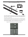
sizes of slide rails that can be mounted on the EIA posts in the SuperRack.
Figure 5-3: Sliding Rails
Component Installation
Various network and server components can be mounted in your SuperRack system.
They may be mounted on shelves if under 3U in height, or directly on the rack's EIA
posts using sliding rails or brackets. See the user's manual for your rack components
for instructions on mounting rails onto their chassis.
Fan Modules
The SuperRack system comes with several different fan modules for mounting in
both the roof as top panels and on specially ventilated doors. The door modules are
between 3U and 14U in size and require only four screws each to install on special
doors. See the "Top and Side Panels" section for details on top panel over fans.
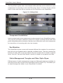
Cable Management Troughs and Fiber Optic Pipes
Different types of cable management troughs and fiber optic pipes are available for
mounting on the rear or sides of the SuperRack sytem (Figure 5-4). This allows you
to easily manage the cables of your SuperRack's contents.
5-18
Chapter 5: Optional Accessories
Figure 5-4: Cable Management Trough
60
100
Tumb Screw
Cover
Base
Latch
These cable mangement troughs come in 1U or 2U models for mounting on EIA
posts and in 54mm or 108mm width by 40mm, 60mm or 80mm length fingers or
cover-over models for mounting on side mounted vertical mounting plates (that are
either 70mm or 130mm wide).
The cable management troughs that mount on EIA posts are secured with cage nuts
and panel screws for mounting on the back EIA posts of the rack. Cable troughs for
side mounting are attached to vertical mounting plates or on rack extensions, and
are mounted by using pegs or slots on the cable trough (see Figure 5-5).
Figure 5-5: Cable Management Trough Pegs and Slots
5-19
SuperRack User's Manual
Mounting a Vertical Plate
In order to mount a cable management trough, you may first need to mount a
vertical plate onto the SuperRack's frame. Cable management troughs mounted
on rack extensions do not need to use a vertical plate since slot and peg holes are
provided on the rack extension already for them. Follow the procedure below for
mounting and unmounting a vertical plate onto the rack frame.
Mounting a Vertical Plate onto the Rack
1. Dismount any side panels that are
on the rear of the SuperRack.
2. Insert spring screw holes on all
horizontal struts in the rack's rear
side where you wish to mount the
vertical plate.
3. Mount the verical plate so that
its screw holes match the spring
screw holes on the horizontal
struts.
4. Screw in the securing screws to
secure the vertical plate to the
rack.
Unmounting a Vertical Plate from the Rack
To unmount a vertical plate from the rack, follow the previous procedure in reverse
by first unscrewing its retaining screws, and then unmounting the vertical plate
from the rack.
5-20
Chapter 5: Optional Accessories
Mounting a Cable Management Trough to a Vertical Plate
To mount a cable management trough to a vertical plate, use the procedure
below.
Mounting a Cable Management Trough to a Vertical Plate
1. Insert the vertical plate's slots
or pegs so that they slide into
the matching slot or peg support
holes on the vertical plate.
2. Screw in the two retaining
thumb screws through the cable
management trough into the
matching holes in the vertical
plate.
Note: The 70mm vertical plate can only mount cable management troughs using
pegs, whereas the 130mm vertical plate and rear extensions can mount cable
managment troughs using both pegs and mounting slots.
Note: You can also mount cable management troughs without a vertical plate
on a bare SuperRack frame by their pegs or slots and by using spring screw
holes to secure them. This method is not as secure as mounting them to a
vertical plate though.
Unmounting a Cable Management Trough from a Vertical Plate
To unmount a cable management trough from a vertical plate on the rack, follow the
previous procedure in reverse by first unscrewing its retaining thumb screws, and
then unmounting the cable management trough from the vertical plate.
5-21
SuperRack User's Manual
Notes
5-22
Appendix A: SuperRack System Specifications
Appendix A
SuperRack System Parts List
Below is list of parts and accessories for the SuperRack system as shown in
Figure A-1. This list is not all inclusive, please see the SuperMicro website or
contact Supermicro for information on the the lastest parts and accessories for the
SuperRack system.
Figure A-1: SuperRack System Parts
Part Number
Descriptions
SRK-42BF-00 42U
Open Basic Frame, 598 x 2020 x 950 mm (WxHxD )
SRK-42BF-01 42U
Open Basic Frame, 598 x 2020 x 950 mm (WxHxD )
SRK-42OR-01 42U
Open Frame Rack, 598 x 2080 x 950 mm (WxHxD )
SRK-42OR-02 42U
Open Frame Rack, 598 x 2080 x 1175 mm (WxHxD)
SRK-42SE-01 42U
Enclosure, 598 x 2080 x 1000 mm (WxHxD )
SRK-42SE-02 42U
Enclosure, 598 x 2080 x 1225 mm (WxHxD )
SRK-00AS-01
Floor Levelers
SRK-00AS-11
M5 Cage Nut
SRK-00AS-12
M6 Cage Nut
SRK-00AS-21
M5 Panel Screw
SRK-00AS-22
M6 Panel Screw
SRK-00AS-31
200 mm Low-resistance Conductive Kit
SRK-00AS-32
400 mm Low-resistance Conductive Kit
SRK-00AS-33
300 mm Low-resistance Conductive Kit
A-1
SuperRack Installation Manual
Part Number
Descriptions
SRK-00AS-41
2.5 inch (63.50 mm) Bolt Down kit
SRK-00AS-42
3.0 inch (76.20 mm) Bolt Down kit
SRK-00AS-51
(optical fiber) Goose Neck Pipe
SRK-03AS-61
Fan Module for Vented Door
SRK-00AS-71
Join Bracket Kits
SRK-00AS-81
APC 0U PDU Adapter Kit
SRK-01CM-01
1U Top Cable Management Trough
SRK-02CM-01
2U Top Cable Management Trough
SRK-03CM-01
3U Top Cable Management Trough
SRK-01CM-11
1U Sided Mounting Cable Management Trough - 30mm (D)
SRK-02CM-11
2U Sided Mounting Cable Management Trough - 50mm (D)
SRK-02CM-12
2U Sided Mounting Cable Management Trough - 60 mm(D)
SRK-01CM-21
1U Single Sided Fingers Cable Management Trough
SRK-02CM-21
2U Single Sided Fingers Cable Management Trough
SRK-01CM-31
1U Double Sided Fingers Cable Management Trough
SRK-02CM-31
2U Double Sided Fingers Cable Management Trough
SRK-01CM-41
1U Bracket with Fingers Cable Management Trough
SRK-02CM-41
2U Bracket with Fingers Cable Management Trough
SRK-20CM-51
20U Vertical Mounting with Fingers Cable Management Trough 54 x 40 mm (W x D)
SRK-20CM-52
20U Vertical Mounting with Fingers Cable Management Trough 54 x 60 mm (W x D)
SRK-20CM-53
20U Vertical Mounting with Fingers Cable Management Trough 54 x 80 mm (W x D)
SRK-20CM-54
20U Vertical Mounting with Fingers Cable Management Trough 108 x 40 mm (W x D)
SRK-20CM-55
20U Vertical Mounting with Fingers Cable Management Trough 108 x 60 mm (W x D)
SRK-20CM-56
20U Vertical Mounting with Fingers Cable Management Trough 108 x 80 mm (W x D)
SRK-42CM-61
42U Vertical Mounting with Fingers Cable Management Trough 54 x 40 mm (W x D)
SRK-42CM-62
42U Vertical Mounting with Fingers Cable Management Trough 54 x 60 mm (W x D)
SRK-42CM-63
42U Vertical Mounting with Fingers Cable Management Trough 54 x 80 mm (W x D)
SRK-42CM-64
42U Vertical Mounting with Fingers Cable Management Trough 108 x 40 mm (W x D)
SRK-42CM-65
42U Vertical Mounting with Fingers Cable Management Trough 108 x 60 mm (W x D)
SRK-42CM-66
42U Vertical Mounting with Fingers Cable Management Trough 108 x 80 mm (W x D)
SRK-42CM-71
42U Vertical Mounting with Cover Over Fingers Cable
Management Trough - 54 x 40 mm (W x D)
SRK-42CM-72
42U Vertical Mounting with Cover Over Fingers Cable
Management Trough - 54 x 60 mm (W x D)
A-2
Appendix A: SuperRack System Specifications
Part Number
Descriptions
SRK-42CM-73
42U Vertical Mounting with Cover Over Fingers Cable
Management Trough - 54 x 80 mm (W x D)
SRK-42CM-74
42U Vertical Mounting with Cover Over Fingers Cable
Management Trough - 108 x 40 mm (W x D)
SRK-42CM-75
42U Vertical Mounting with Cover Over Fingers Cable
Management Trough - 108 x 60 mm (W x D)
SRK-42CM-76
42U Vertical Mounting with Cover Over Fingers Cable
Management Trough - 108 x 80 mm (W x D)
SRK-42CM-81
42U Vertical Mounting Post with Finger Cable Management
Trough - 70 mm (D)
SRK-42CM-82
42U Vertical Mounting Post with Finger Cable Management
Trough - 130 mm (D)
SRK-00CT-03
3.0 inch Heavy-duty Swivel Casters (454 kg / 1000 lbs per Caster)
SRK-42DR-01
42U Filter Door
SRK-42DR-02
42U Solid Door
SRK-42DR-03
42U Split Meshed Door
SRK-42DR-04
42U Vented Door
SRK-42DR-05
42U Meshed Door
SRK-42DR-06
42U Meshed inlaid with Tempered Glass Door
SRK-42DR-07
42U Meshed inlaid with Diaphanous Acrylic Door
SRK-42DR-08
42U Meshed inlaid with Brown Acrylic Door
SRK-42EU-01
42U Expansion Unit - 100 mm
SRK-42EU-02
42U Expansion Unit - 150 mm
SRK-42EU-03
42U Expansion Unit - 200 mm
SRK-42EU-04
42U Expansion Unit - 225 mm
SRK-42EU-05
42U Expansion Unit - 300 mm
SRK-42EU-06
42U Sided Expansion Unit - 75 mm
SRK-42MP-01
42U Round Hole Mounting Post - Front Left and Rear Right
SRK-42MP-02
42U Round Hole Mounting Post - Front Right and Rear Left
SRK-42MP-11
42U Square Hole Mounting Post - Front Left and Rear Right
SRK-42MP-12
42U Square Hole Mounting Post - Front Right and Rear Left
SRK-42MP-31
42U Vertical Mounting Plate - 70 mm (W)
SRK-42MP-32
42U Vertical Mounting Plate - 130 mm (W)
SRK-42MP-41
42U Sided Vertical Mounting Post
SRK-01PN-01
1U Mesh Blanking Panel
SRK-02PN-01
2U Mesh Blanking Panel
SRK-03PN-01
3U Mesh Blanking Panel
SRK-04PN-01
4U Mesh Blanking Panel
SRK-05PN-01
5U Mesh Blanking Panel
SRK-07PN-01
7U Mesh Blanking Panel
SRK-08PN-01
8U Mesh Blanking Panel
SRK-16PN-01
16U Mesh Blanking Panel
SRK-01PN-11
1U Solid Blanking Panel
A-3
SuperRack Installation Manual
Part Number
Descriptions
SRK-02PN-11
2U Solid Blanking Panel
SRK-03PN-11
3U Solid Blanking Panel
SRK-04PN-11
4U Solid Blanking Panel
SRK-05PN-11
5U Solid Blanking Panel
SRK-07PN-11
7U Solid Blanking Panel
SRK-08PN-11
8U Solid Blanking Panel
SRK-16PN-11
16U Solid Blanking Panel
SRK-03PN-21
3U Top Panel Over 2 Fans - AC 120V
SRK-03PN-22
3U Top Panel Over 2 Fans - AC 208V
SRK-03PN-31
3U Top Panel Over 3 Fans - AC 120V
SRK-03PN-32
3U Top Panel Over 3 Fans - AC 208V
SRK-06PN-41
6U Top Panel Over 4 Fans - AC 120V
SRK-06PN-42
6U Top Panel Over 4 Fans - AC 208V
SRK-14PN-51
14U Top Panel Over 2 Fans - AC 120V
SRK-14PN-52
14U Top Panel Over 2 Fans - AC 208V
SRK-20PN-61
42U 2-Sectional Removable Mesh Side Panel
SRK-20PN-62
42U 2-Sectional Removable Solid Side Panel
SRK-03PN-71
3U Top Panel Over 2 Openings
SRK-00PT-01
Reusedable Steel Pallet, 350 kg / 772 lbs
SRK-00PT-02
Reusedable Steel Pallet, 550 kg / 1212 lbs
SRK-00PT-03
Reusedable Steel Pallet, 750 kg / 1653 lbs
SRK-00PT-04
Reusedable Steel Pallet, 1050 kg / 1709 lbs
SRK-00PT-05
Reusedable Steel Pallet, 1250 kg / 2756 lbs
SRK-01SF-01
1U Fixed Vented Shelf
SRK-02SF-01
2U Fixed Vented Shelf
SRK-03SF-01
3U Fixed Vented Shelf
SRK-01SF-11
1U Fixed Solid Shelf
SRK-02SF-11
2U Fixed Solid Shelf
SRK-03SF-11
3U Fixed Solid Shelf
A-4


![`95385109 1%]?](http://vs1.manualzilla.com/store/data/005699459_1-7fc02fda0f8970d7c2f678aea00486d8-150x150.png)