1
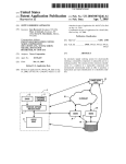
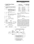
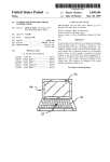
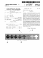
US006034711A
Ulllted States Patent [19]
[11] Patent Number:
Trask et al.
[45]
[54]
SELF-INDICATING TEST PAGE FOR USE IN
SETTING DENSITY LEVEL AND COLOR
BALANCE IN A COLOR LASER PRINTER
Date of Patent:
3-69272
4-170268
_
3/1991
6/1992
6,034,711
Mar. 7, 2000
Japan ............................. .. H04N 1/46
Japan ............................. .. H04N 1/40
_
Primary Exammer—N. Le
Assistant Exammer—Hai C- Pham
[75]
Inventors: Jeffrey L. Trask; Brian Ho?'mann,
[73]
Assignee? bOth
Hewlett'packard
Of Boise,
Company, P2110 Alto,
Calif
A test page, system, and method are used to set a color
density level of a laser printer, by producing a dot gain test
pattern. The laser printer has at least one primary color. The
[21]
Appl. No.: 08/611,892
dot gain test pattern is self-indicating and thus requires no
_
external reference in order to determine a correct color
[22]
Flled:
Mar‘ 6’ 1996
density level. A preferred embodiment of the dot gain test
[51]
[52]
Int. c1.7 ................................................... .. G03G 15/01
US. Cl. ........................ .. 347/240; 347/251; 347/254;
Pattern includes (a) a Stable Pattern having a Color density
which is Stable With respect ‘0 Changes in the laser Printer
[58]
399/39; 399/49; 399/72
Field of Search ................................... .. 347/240 254
347/251_ 399/39 49 72’ 181’
operating conditions, and (b) a sensitive pattern having a
colorflensity Whi‘Fh is sensiFiYe to Chang‘? in the Operating
conditions, wherein the sensitive pattern in reference to the
’
[56]
’
’
’
stable pattern indicates the density level of the laser printer
References Cited
for the at least one primary color. Additionally, in a preferred
embodiment, the stable pattern includes a uniform coarse
4 310 248
576047567
’
U.S. PATENT DOCUMENTS
1/1982 Meredith
2/1997 Dundas
356/402
.... .. 399/39
’
printer for the at least one primary color is indicated When
FOREIGN PATENT DOCUMENTS
0518525
a mid-spectrum area of the ?ne dot gradient appears to blend
12/1992
European Pat. on. ....... .. H04N 1/46
0658962 12/1995
62-251628 11/1987
European Pat. Off.
H04N 1/60
Japan .............................. .. G01] 3/52
mm the Coarse dot pattern‘
11 Claims, 4 Drawing Sheets
/10
25
15
dot pattern, and the sensitive pattern includes a gradient of
?ne dot densities, the gradient printed adjacent to the coarse
dot Pattern’ wherein a Correct density level of the laser
20
U.S. Patent
Mar. 7,2000
Sheet 1 of4
an
m
6,034,711
U.S. Patent
Mar. 7, 2000
Sheet 2 0f 4
6,034,711
0.50
0.45
0.40
ODPETNISCALY
0.35
0.30
0.25
0.20
0.15
0.10
-2
-I
0
+1
DENSITY SETTING
+2
+ 26dpi +150|pi+ 300|pi
SENSITIVITY vs. DOTS/LINES PER INCH
FIG. 2
U.S. Patent
Mar. 7,2000
I
START
Sheet 3 of4
I
110
I
I
//
PRINT DDT GAIN
TEST PATTERN
DDES
PATTERN
INDICATE A NEED
FOR ADJUSTMENT
DF CDLDR
DENi’SlTY
YES
ADJUST CDLOR
DENSITY LEVEL AS
INDICATED BY
TEST PATTERN
FIG. 3
6,034,711
U.S. Patent
Mar. 7, 2000
Sheet 4 of4
6,034,711
220
%%@
FIG. 4
“V
Y+ E5
M+
210
/
/
M+
,
6,034,711
1
2
SELF-INDICATING TEST PAGE FOR USE IN
SETTING DENSITY LEVEL AND COLOR
BALANCE IN A COLOR LASER PRINTER
Which is sensitive to changes in the operating conditions,
Wherein the sensitive pattern in reference to the stable
pattern indicates the density level of the laser printer for the
at least one primary color.
FIELD OF THE INVENTION
According to further principles of the present invention in
a preferred embodiment, the stable pattern includes a uni
form coarse dot pattern, and the sensitive pattern includes a
This invention relates in general to image transfer tech
nology and, more speci?cally, to a self-indicating test page
for use in setting color density level in a laser printer.
BACKGROUND OF THE INVENTION
In laser printers, both the engine electro-photographic
(EP) process control tables and the formatter pulse-Width
(PW) control tables are based on print quality characteriZa
tion done during life testing. HoWever, factors such as the
usage rate, EP process components, and printing environ
gradient of ?ne dot densities, the gradient printed adjacent to
10
Other objects, advantages, and capabilities of the present
invention Will become more apparent as the description
15
FIG. 1 is a dot gain test pattern produced by a laser printer
using a preferred embodiment of the present invention.
FIG. 2 is a graph shoWing the dot sensitivity to changes
in developer AC bias voltage and/or laser poWer versus dots
These color differences are a signi?cant cause of service
per inch or lines per inch.
FIG. 3 is a How chart shoWing a preferred method of the
25
present invention.
FIG. 4 is a preferred embodiment of a gray balance test
detectors inside the printer. The optical density detectors
provide feedback to the printer Which, in turn, adjusts the
color density levels. This approach adds cost and complexity
pattern.
DETAILED DESCRIPTION OF THE
INVENTION
to the printer. Another approach is to print out a test page and
to compare the test page With a reference page, typically
included in the user’s manual. This approach is
inconvenient, because it requires the user to keep track of the
FIG. 1 is a preferred embodiment of a dot gain test pattern
10 produced by a laser printer according to principles of the
present invention for testing the optical density of a color of
reference page, and dif?cult, because it requires from the
user the ability to accurately compare the test page With the
reference page.
In order to maintain consistent color densities in offset
proceeds.
DESCRIPTION OF THE DRAWINGS
ment Will vary over time. It is not possible to anticipate hoW
these factors Will vary from life test conditions. Changes in
these factors cause noticeable and typically objectionable
color density differences betWeen printers over time.
calls on color laser printers, Which usually result in replace
ment of the drum cartridge and/or replacement of the color
developer. Prior methods of correcting the color differences
Without a service call include installing optical density
the coarse dot pattern, Wherein a correct density level of the
laser printer for the at least one primary color is indicated
When a mid-spectrum area of the ?ne dot gradient appears to
blend into the coarse dot pattern.
35
printing, a dot gain test is used. In the color printing industry,
offset printing is the standard for producing high quality,
the laser printer. The test pattern 10 is typically printed on a
test page by the laser printer. The dot gain test pattern 10
comprises a portion that is a uniform coarse dot pattern 15
and a portion that is a ?ne dot gradient 20. In this
embodiment, arroWs 20, disposed across the page, represent
the ?ne dot gradient 20. Obviously, hoWever, other patterns
color results. A dot gain test compares the appearance of ?ne
dots With the appearance of much coarser dots. The high
perimeter/area ratio of the ?ne dots makes them much more
could equally be used. The coarse dot pattern 15 is uniform
in optical density. In a preferred embodiment the coarse dot
pattern 15 is 26 dots per inch (dpi). The ?ne dot gradient 20
sensitive to factors that cause more or less ink to be
varies in optical density, producing a spectrum ranging from
high to loW optical density. In the ?gure, high to loW density
deposited. A gradient of ?ne dot densities is printed in a
uniform coarse dot background. When vieWed from a dis
is portrayed from left to right, varying from arroW 20 to
tance Where the coarse dots cannot be independently 45
arroW 20 across the page, each arroW 20 having a uniform
distinguished, the mid-spectrum area of the ?ne dot gradient
blends into the coarse dot background, if the color density is
density. The optical density of the ?ne dot gradient 20 is
varied by pulse-Width modulation of the laser beam to
produce the spectrum of optical densities. In a preferred
embodiment, the ?ne dot gradient 20 is 150 lines per inch
correct.
Accordingly, given the forgoing backgrounds relating to
offset printing, color laser printers, and color density levels,
(Lpi). In a laser printer With a correct density level, at some
objects of the present invention are to provide a neW test
point along the ?ne dot gradient 20 (across the page), the
page, system, and method for setting the color density level
of a laser printer.
SUMMARY OF THE INVENTION
55
point Where the optical densities essentially match, the ?ne
According to principles of the present invention in a
dot gradient 20 Will appear to blend in With the coarse dot
preferred embodiment, a test page, system, and method are
used to set a color density level of a laser printer, by
background 15.
providing a dot gain test pattern. The laser printer has at least
one primary color. The dot gain test pattern is self-indicating
Although the test pattern 10 is shoWn using only the color
black, the test pattern 10 Will Work equally Well for any of
the primary colors of a laser printer. For a typical laser
printer, the only primary color is black
For a color laser
printer the additional primary colors are typically cyan,
and thus requires no eXternal reference in order to determine
a correct color density level.
A preferred embodiment of the dot gain test pattern
includes (a) a stable pattern having a color density Which is
stable With respect to changes in the laser printer operating
conditions, and (b) a sensitive pattern having a color density
optical density of the ?ne dots Will essentially match the
optical density of the uniform coarse dot background 15. A
laser printer With a correct density level Will produce pat
terns With an optical density of essentially 0.27:0.05. At the
65
magenta, and yelloW (CMY).
In a preferred embodiment for a correct color density, the
point at Which the ?ne dot gradient 20 blends into the coarse
6,034,711
3
4
dot pattern 15 is located in the area 25 mid-spectrum across
the gradient 20. A correct color density indicates that no
printers are not self-indicating because they rely on a
comparison betWeen the test pattern and some external
reference. Typically the external reference is included in the
user’s manual. The external reference could also be the
change in color density is needed. If the point at Which the
?ne dot gradient 20 blends into the coarse dot pattern 15 is
not located in the area 25 mid-spectrum across the gradient
20, then a need for a change in color density is indicated. In
memory of the user. If a user has to look at a test pattern and
use judgement to determine if the color density appears
correct, the user’s memory of What a correct color density
this embodiment, if the point at Which the ?ne dot gradient
20 blends into the coarse dot pattern 15 is located to the left
of the mid-spectrum area 25, then a need for an increase in
color density is indicated. Conversely, if the point at Which
the ?ne dot gradient 20 blends into the coarse dot pattern 15
is located to the right of the mid-spectrum area 25, then a
need for a decrease in color density is indicated.
The ?ne dots Which make up the ?ne dot gradient 20 are
actually fractions of a full dot. As such, the ?ne dots do not
looks like is an external reference.
10
for the laser printer has the ability to modify the developer
AC bias voltage and the laser poWer. In a preferred
15
receive full exposure to the drum. The ?ne dots are very
sensitive to changes in the operating conditions of the printer
because of their less than full exposure to the drum. In
contrast, the coarse dots are actually clusters of full dots.
Each full dot receives full exposure to the drum.
20
Accordingly, the coarse dots are not very sensitive to
changes in the operating conditions of the printer. Changes
in the operating conditions Which may affect the color
density produced by the laser printer include, but are not
limited to, humidity, temperature, the discharge voltage of
25
the photoconductor, laser poWer, developer AC bias, toner
charge, and frequency of use.
Differences in sensitivity to the operating conditions can
be demonstrated by shoWing hoW the different dot siZes react
to a change in laser poWer and/or developer AC bias voltage.
30
35
FIG. 3 is a How chart shoWing a preferred method of the
present invention. Referring to FIGS. 1 and 3, the ?rst step
pattern 10 indicates Whether the color density needs to be
adjusted and Whether the color density needs to be increased
or decreased. If the color density does need to be adjusted,
the user adjusts the color density 120 as indicated for the
primary color in Which the test pattern 10 Was printed.
Another dot gain test pattern 10 is then printed 110 in the
bias increases.
40
over the range from 26 dpi to 300 Lpi, the effect of a change
same color as the ?rst dot gain test pattern 10. If the test
pattern 10 indicates that another adjustment in color density
is necessary, the process is repeated until the color density
for the tested color is correct.
in density setting on the optical density, also increases. At 26
dpi, the optical density varies from approximately 0.24 to
Lpi, the optical density varies from approximately 0.13 to
0.50 for the same change in density setting.
developer AC bias voltage and the laser poWer. The density
setting is adjusted in reference to the dot gain test pattern 10
is to print 110 a dot gain test pattern 10 in a primary color.
Next, the test pattern 10 is examined by a user 115. The test
the relationship betWeen the dpi (or Lpi) and the change in
0.29 for a change in density setting from —2 to +2. At 300
bias increases.
The area along the ?ne dot gradient 20 that blends in With
the coarse dot pattern 15 Will be shifted by a change in the
developer AC bias voltage or the laser poWer. This shift is
due to the difference in hoW the ?ne dot gradient 20 and the
coarse dot pattern 15 are affected by the change in the
high.
FIG. 2 graphically shoWs the difference in sensitivity
The graph clearly shoWs that as the dpi (or Lpi) increases
embodiment, adjustments in the laser poWer and/or devel
oper AC bias voltage from the normal electro-photographic
(EP) process tables are represented by a change in a density
setting. As discussed above, typically, as the setting
increases, the laser poWer increases and the developer AC
Which indicates Whether the color density is too loW or too
betWeen the ?ne dots and the coarse dots. The graph shoWs
optical density caused by a change in laser poWer and/or
developer AC bias voltage. These changes in laser poWer
and/or developer AC bias voltage are represented by
changes in a density setting. In general, as the setting
increases, the laser poWer increases and the developer AC
In order to remedy an incorrect color density, compensa
tion is made to account for the change in operating condi
tions from life test conditions. The process control engine
Although reference has been made only to one dot gain
45
test pattern 10 on the test page, it is noted that multiple dot
gain patterns 10, each for a different primary color may be
printed on each test page.
Since the ?ne dots are much more sensitive to the oper
In addition to a dot gain test, a gray balance test may be
ating conditions than the coarse dots, the optical density of
printed on the test page. A gray balance test is also referred
the ?ne dots is affected much more than the optical density 50 to as a neutral gray test. A gray balance test is employed in
of the coarse dots by a change in the operating conditions.
Therefore, a change in operating conditions results in a shift
of the area along the ?ne dot gradient 20 Where the ?ne dots
order to balance the color densities of the primary colors,
typically CMY. The gray balance test is also a more visible
appear to blend into the coarse dot background. The coarse
dot pattern 15 acts as a stable reference compared to the ?ne 55
dot gradient 20, thus the test page is self indicating and no
external reference is needed.
Since the ?ne dot gradient 20 is affected more than the
colors, a light neutral gray area is produced using only the
primary colors CMY. Another light neutral gray area is
produced using only the color black. The tWo areas of light
neutral gray are compared. If the balance of CMY colors is
coarse dot pattern 15 by changes in operating conditions, the
coarse dot pattern 15 has a stable optical density, relative to
60
the optical density of the ?ne dot gradient 20, for all
acceptable operating conditions. Acceptable operating con
ditions are those operating conditions Which alloW the laser
printer to function properly as a laser printer.
The dot gain test pattern 10 is self-indicating because no
external reference is needed in order to determine if the color
density is correct. Other types of test patterns for laser
Way to check for the correct amount of yelloW color density
than the dot gain test pattern 10.
In order to balance the color densities of the primary
not correct, the “neutral gray” produced With only CMY Will
have a noticeable hue compared to the same neutral gray
produced With only black.
In a preferred embodiment, the gray balance test pattern
is composed of 25 circles in a grid, as shoWn in FIG. 4. The
65
grid background 215 is a light neutral gray color composed
of black only. The circles 205 are also a light neutral gray
color, but composed of CMY only. Each circle has a slightly
6,034,711
6
5
different hue representative of a high or loW density of one
or tWo of the primary colors. The circles are arranged so that
they constitute a tWo directional spectrum ranging from loW
magenta, and yelloW.
to high density for each of tWo primary colors in each of the
tWo directions. In this embodiment, the density of yelloW
printer, the laser printer having at least one primary color,
varies from loW to high in the direction from the bottom of
the pattern to the top and magenta varies from loW to high
in the direction from left to right.
The center circle 210 of the gray balance test should
match the background 215. If the center circle 210 does not
5. The test page of claim 4 Wherein at least one primary
color is selected from the group consisting of black, cyan,
6. A system for setting a color density level of a laser
the system comprising:
(a) means for producing a stable pattern having a color
density Which is stable With respect to changes in
operating conditions of the laser printer;
10
match the background 215, a change in color density is
indicated. If a circle other than the center circle 210 matches
the background 215, the test pattern indicates hoW the
density levels should be changed in order to obtain a correct
color balance.
15
For example, if the upper right circle 220 matches the
(b) means for producing a sensitive pattern having a color
density Which is sensitive to changes in the operating
conditions of the laser printer; and,
Wherein the sensitive pattern in reference to the stable
pattern indicates, Without reference to any other
source, the density level of the laser printer for the at
least one primary color.
7. The system of claim 6 Wherein the stable pattern
background 215, the magenta and yelloW color density
includes a uniform coarse dot pattern, and Wherein the
levels are both too loW. Since the matching circle 220 is tWo
circles aWay from the center circle 205 in both the horiZontal
sensitive pattern includes a gradient of ?ne dot densities, the
gradient printed adjacent to the coarse dot pattern, Wherein
a correct color density level of the laser printer for the at
least one primary color is indicated When a mid-spectrum
and vertical directions, both magenta and yelloW should be
increased by tWo density levels.
area of the ?ne dot gradient appears to blend into the coarse
In summary, What has been described above are the
dot pattern.
preferred embodiments for a system and method for setting
the color density level of a laser printer and a test page for
use in setting the color density level of a laser printer. While
the present invention has been described by reference to
speci?c embodiments, it Will be obvious that other alterna
tive embodiments and methods of implementation or modi
?cation may be employed Without departing from the true
spirit and scope of the invention.
What is claimed is:
1. A test page produced by a laser printer, the laser printer
having at least one primary color, the test page for setting a
density level of the laser printer for the at least one primary
color, the test page comprising:
(a) a stable pattern having a color density Which is stable
With respect to changes in operating conditions of the
25
35
in reference to the stable pattern indicates, Without
reference to any other source, the density level of the
laser printer for the at least one primary color of the
laser printer; and,
(c)adjusting the color density level of the laser printer for
laser printer;
the at least one primary color based on visual obser
vation of the sensitive pattern in reference to the stable
(b) a sensitive pattern having a color density Which is
sensitive to changes in the operating conditions of the
pattern.
9. The method of claim 8 Wherein the stable pattern
laser printer; and,
Wherein the sensitive pattern in reference to the stable
pattern indicates, Without reference to any other
source, the density level of the laser printer for the at
least one primary color.
2. The test page of claim 1 Wherein the stable pattern
8. A method for setting a color density level of a laser
printer, the laser printer having at least one primary color,
the method comprising:
(a) printing a stable pattern having a color density Which
is stable With respect to changes in operating conditions
of the laser printer;
(b) printing a sensitive pattern having a color density
Which is sensitive to changes in the operating condi
tions of the laser printer, Wherein the sensitive pattern
includes a uniform coarse dot pattern, and Wherein the
45
sensitive pattern includes a gradient of ?ne dot densities, the
gradient printed adjacent to the coarse dot pattern, Wherein
a correct color density level of the laser printer for the at
least one primary color is indicated When a mid-spectrum
includes a uniform coarse dot pattern, and Wherein the
area of the ?ne dot gradient appears to blend into the coarse
sensitive pattern includes a gradient of ?ne dot densities, the
gradient printed adjacent to the coarse dot pattern, Wherein
dot pattern.
10. The method of claim 8 further including repeating
steps (a) and (b) until the color density level is correct.
11. The method of claim 8 further including:
(a) printing a gray balance test pattern; and,
(b) further adjusting the color density level of the laser
a correct density level of the laser printer for the at least one
primary color is indicated When a mid-spectrum area of the
?ne dot gradient appears to blend into the coarse dot pattern.
3. The test page of claim 1 Wherein at least one primary
color is selected from the group consisting of black, cyan,
magenta, and yelloW.
4. The test page of claim 1 further including a gray
balance test pattern.
55
printer for the at least one primary color based on visual
observation of the gray balance test pattern.