1
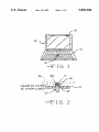
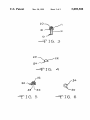
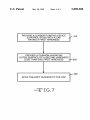
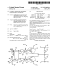
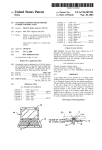
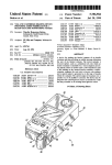
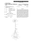
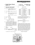
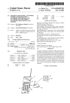
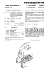
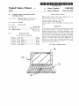
US005889508A
Ulllted States Patent [19]
[11] Patent Number:
Slotta
[45]
[54]
Date of Patent:
CUSHION FOR KEYBOARD CURSOR
Inventor:
Mar. 30, 1999
OTHER PUBLICATIONS
CONTROL STICK
[76]
5,889,508
_
IBM ThinkPad 750 and 750C User’s Manual, pp. 4—27
Mark R. Slotta, 724 OakWood Dr.,
West Bloom?eld’ Mlch' 48322
through 4—29> dated Prior to invention
Primary Examiner—l\/l ark K. Zimmerman
Assistant Examiner—Ronald Laneau
[21] Appl- N05 717,220
[22] Filed:
Sep. 26, 1996
Attorney, Agent, or Firm—MacMillan, Sobanski & Todd,
LLC
[51]
Int. C16 ..................................................... .. G09G 5/08
[57]
[52]
[58]
US. Cl. ........................................... .. 345/161; 345/157
Field Of Search ................................... .. 345/161, 168,
Acushion that can be attached to an existing Cursor pointing
device (Control Stick) on a Computer or keyboard, or be
345/157, 160
_
References Clted
[56]
ABSTRACT
integrally formed With the cap during manufacture. The
cushion is ?exible enough to prevent tissue damage to the
user’s ?ngers due to repetitive motions over an extended
Us‘ PATENT DOCUMENTS
period of use, yet ?rm 'enough to transmit 'the desired
pressure to the control stick. The cushion designed to be
5,488,206
1/1996 Wu ........................................ .. 200/511
575687987 10/1996 Fran? ~~~~ ~~
400/490
5570412 10/1996 Robmson '
" 345/163
used on an existing Control stick can be applied With an
adhesive to a cap, or With a frictional ?t directly to the
control stick. The cushions are designed to be easily
5,670,988
installed and re laced When Worn
5,701,142
5,708,562
5,712,660
9/1997 Tickle ........ ..
12/1997
Brown et a1. .
345/161
.. 345/168
1/1998 Agata et a1. ..
345/161
1/1998 Martin ................................... .. 345/161
p
23 Claims, 3 Drawing Sheets
\
\\
F\
'
U.S. Patent
Mar. 30, 1999
I----
7-
Sheet 1 of3
_
\NS\DE OF COVER"
\5 WHEN cwswm
5,889,508
_
;
'
\1
U.S. Patent
Mar. 30, 1999
Sheet 2 of3
2O
5,889,508
22
24
FIG.
s2
34
33
34
;F I G. 5
3O
416.6
U.S. Patent
Mar. 30, 1999
Sheet 3 of3
5,889,508
PROVIDE A CURSOR POINTING DEVICE
(CONTROL STICK) WITH A CAP
100
//
HAVING A FIRST HARDNESS
PROVIDE A CUSHION HAVING AN
OUTER SURFACE OF A SECOND HARDNESS
LESS THAN SAID FIRST HARDNESS
—-—2OO
’/ 300
AFFIX THE SOFT CUSHION TO THE CAP
—"::'IG.7
5,889,508
1
2
CUSHION FOR KEYBOARD CURSOR
CONTROL STICK
invention provides a “cushioned” cap for a control stick With
a surface Which provides the needed ?nger to cap friction to
easily use the control stick to move the cursor With a light
touch, and Which is formed of a relatively soft material so
that the cap does not irritate the body tissues of the user or
BACKGROUND OF THE INVENTION
This invention relates in general to a computer input
device, and in particular to a cursor pointing device (cursor
control stick), of a notebook-type portable computer or
similar device.
A ?nger mouse or cursor control stick, as used in this
application, is a man-machine interface device Which con
trols the motion of a computer display cursor. In particular,
a control stick is a type of miniature joy stick Which is
intended to be operated by the tip of one ?nger of the user.
Typically, a control stick is mounted in a central location
on a computer keyboard, such as betWeen the “G”, “H” and
“B” keys on a standard “QWERTY”-type keyboard. The
control stick has a position sensing mechanism Which
detects horiZontal pressure in any horiZontal direction. The
result in ?nger fatigue, even after periods of extended use.
Various objects and advantages of this invention Will
become apparent to those skilled in the art from the folloW
10
ing detailed description of the preferred embodiment, When
read in light of the accompanying draWings.
BRIEF DESCRIPTION OF THE DRAWINGS
15
cursor moves in a direction that corresponds to the direction
of pressure exerted on the control stick and, in some
FIG. 1 is a perspective vieW of a typical portable com
puter employing a control stick having a cushioned cap in
accordance With this invention.
FIG. 2 is a side vieW, partly in section, of the control stick
illustrated in FIG. 1.
FIG. 3 is an enlarged sectional side vieW of the cap and
the control stick illustrated in FIGS. 1 and 2.
FIG. 4 is a side vieW of the cushioned cap illustrated in
embodiments, at a speed that corresponds to the amount of
FIGS. 1 through 3.
pressure exerted on the control stick. The control stick
FIG. 5 is a sectional side vieW of a second embodiment of
includes an elongated shaft. The shaft of the control stick has
a small diameter, thus alloWing the control stick to be 25 a cushioned cap in accordance With this disclosure.
mounted betWeen the keys of the computer keyboard With
FIG. 6 is a bottom plan vieW of the cap illustrated in FIG.
out causing the placement of the keys to vary greatly from
5
that expected by an experienced user. A cap is typically
FIG. 7 is a ?oWchart illustrating a method of manufac
removably mounted on the upper end of the control stick
turing a control stick in accordance With this disclosure.
shaft, in order to provide an enlarged contact surface for a
user to press against on the small diameter shaft of the
DETAILED DESCRIPTION OF THE
control stick.
PREFERRED EMBODIMENT
SUMMARY OF THE INVENTION
Referring noW to the draWings, FIGS. 1 through 6 illus
Some models of control sticks have a cap With a hard 35 trate a ?rst embodiment of a control stick, indicated gener
ally at 10, according to this invention. The illustrated control
stick 10 is a miniature joy stick, such as the TrackPoint,
smooth surface, Which became slippery during use from
perspiration or a build-up of natural body oils. Thus a user
TrackPoint II, or TrackPoint III control sticks on notebook
has to press their ?nger With relatively great force against the
computers sold by the International Business Machines
Corporation. HoWever, it Will be appreciated, in light of the
folloWing disclosure, that the invention may be practiced on
control devices other than such miniature joy sticks.
cap to prevent their ?nger from slipping on the surface of the
cap. The need to press hard on the cap makes control
dif?cult, since the user cannot use the ?nesse and delicate
movements typically needed for rapid, accurate cursor
movement. Also, pressing hard on the control stick is
physically tiring to the ?nger, hand and forearm muscles of
a user, and caused irritation, in?ammation, and bruising of
The control stick 10 is mounted in a keyboard 12 of a
typical notebook-style microcomputer 14 having a pivotally
45
the ?nger tissue after a period of extended use.
A period of extended use, as used in this application,
a ?rst end (not shoWn) to the microcomputer 14, betWeen the
keys of the keyboard 12. Acap 18 is removably mounted on
the other end 21 of the control stick 10. The control stick 10
is usually made of a plastic material, and translates the
means a period of use of more than about one hour, and
generally more than four hours and less than tWelve hours.
pressure on the cap 18 into a command to move a cursor on
During such period of use, the user frequently manipulates
the control stick. The frequency of manipulation of the
control stick during a representative task, such as Word
processing, Will typically be at least every ten minutes, on
average, and may be much more frequently, depending on
the particular task and the particular user.
mounted video screen 15. The control stick 10 is mounted at
a video display of the computer 14.
The cap 18 of the control stick 10 is made of a relatively
hard elastomeric material. At least a central portion of the
outer surface 17 of the cap 18 is provided With an attached
55
Another type of a cap for a control stick has a textured
cushion 20. The cushion 20 can be made of any resilient
material that can be attached to the outer surface 19 of the
cap 18. Examples Which may be suitable materials include
outer surface. For example, one knoWn control stick is
equipped With a cap Which is stippled With bumps Which are
soft rubber, soft foam, and polyurethane foam. The preferred
about the same siZe and spacing as the abrasive on 150 grit
material for the cushion 20 is polyurethane foam such as the
sandpaper. While this approach may help prevent the slip
type used in expandable ear plugs. This type of foam product
ping common With the earliest model cap, the textured cap
is still irritating to the ?nger of a user When used extensively,
even With the lighter touch alloWed by the textured surface.
The uneven and relatively hard surface of such caps still can
provides a surface that is relatively soft so as to not damage
cause in?amed tissue, bruising, soreness and ?nger fatigue
in users Which limits their ability to comfortably use such a
control stick for periods of extended use. The present
the tissues in the ?nger of a user during periods of extended
use.
Hardness can be characteriZed by measuring the force
65
applied to a given area Which is required to compress or
de?ect a material a given distance. For example, a typical
prior art cap, such as a cap supplied With the TrackPoint II
5,889,508
3
4
control stick, is made of a relatively hard elastomeric
material. During testing, a probe having a contact surface of
approximately 1 mm2 Was pressed against such a cap to
cause the probe to de?ect the surface of the cap approxi
mately 0.25 mm. A force of approximately 15 grams Was
required to compress the surface of the cap inWardly this
A recess 34 is de?ned in the cushion 30, Which generally
conforms to the outer surface of the end 21 of the control
stick 10. For example, as shoWn in FIG. 6, the recess 34 may
have a square perimeter, if the end 21 of the control stick 10
is square in cross-section. The control stick 10 extends into
the recess 34. Preferably, to install the cushion 30 onto the
control stick 10, a suitable adhesive is applied to the upper
end 21 of the control stick, to the interior surface of the
small amount. In contrast, one embodiment of the cushion
20 of the present invention required a force of only 5 grams
to be exerted by the probe to compress the surface of the
recess 34 in the cushion 30, or to both the upper end 21 of
the
control stick and to the interior surface of the recess 34
10
in the cushion 30. The cushion 30 is placed on the end 21 of
cushion 20 having a hardness Which Would permit a probe
the control stick 10 so that the cushion 30 adheres to the end
having a contact surface of approximately 1 mm2 to de?ect
the surface of the cushion 20 by at least 0.25 mm When urged
21 of the control stick 10. Of course, the cushion 30 could
also be af?xed to the control stick 10 by a resilient ?t
by a force of 10 grams Would generally be acceptable. The
preferred embodiment of the invention has a hardness such 15 betWeen the recess 34 of the cushion 30 and the end 21 of
the control stick 10. The cushion 30 is comprised of a soft
that only 5 grams of force is required to cause a probe having
a contact surface of 1 mm2 to de?ect the surface of the
material to permit use for an extended period of time Without
cushion 20 by at least 0.25 mm.
causing irritation to the ?nger tissue.
It may be desirable to manufacture the cushion 30 With
Preferably, the cushion 20 also provides a high coef?cient
cushion 20 the same distance. According to the invention, a
of friction With the user’s ?nger to permit easy positioning
of the control stick 10. The polyurethane foam of the cushion
20 is yielding to a degree dependent upon the thickness of
the cushion 20. The thickness of the cushion 20 can easily
be modi?ed during manufacture to any desired thickness.
Referring to FIG. 2, When the display 15 is folded doWn
over the keyboard 12 for storage, as is typical for most
notebook computers, the display 15 may contact the cushion
20. The cushion 20 is ?attened as indicated by the phantom
line 19, but Will resiliently return to the position indicated by
the solid outline of the cushion 20. The resiliency of the
20
the convex end 32 could be softer than the area of the
cushion 30 surrounding the recess 34. The harder area
25
Where the convex end 32 is formed, and a second material
35
the mold at the area Where the recess 34 is formed. Accel
erating agents, compatabiliZing agents, ?llers, mold release
agents, and coloring agents can be introduced as Well, as Will
be appreciated by those skilled in the art. SomeWhere
betWeen the tWo ends 32 and 33, the ?rst and second
40
materials come into contact and become af?xed to one
another. The cushion 30 Would, therefore, be a single
structure formed from tWo different materials, having dif
section. HoWever, the cushion 20 may have any suitable
shape, such as that of a ?at-ended or holloW-ended cylinder.
In the illustrated embodiment, the cushion 20 has a convex
end 22, and a second end 24. The convex end 22 is the
contact surface of the cushion 20, that is, the surface that the
simultaneously into a cavity of single mold to form the
cushion 30. For example, a ?rst material having relatively
soft properties Would be injected in the mold at the area
Which is harder than the ?rst material Would be injected in
Referring to FIGS. 3 and 4, the cushion 20 is, preferably,
a disk of material having a generally semi-circular cross
surrounding the recess 34 Would assist in retaining the
cushion 30 on the control stick 10 by maintaining its form,
While the convex end 32 of the cushion could be relatively
soft.
One method of manufacturing the cushion 30 With por
tions having different levels of hardness Would involve
simultaneously injecting tWo separate types of material
30
cushion 20 alloWs the cap 18 to have an enlarged contact
surface area and greater height above the keyboard 12 for
increased comfort of the user, Without having to increase the
spacing betWeen the screen 15 and the keyboard 12. It Will
be appreciated by those skilled in the art that the cushion 20
Will preferably not be made from a material Which Would
damage or stick to the display 15 if the display 15 contacts
the cushion 20.
portions having different levels of hardness. For example,
ferent hardness characteristics When set or cured. For the
purposes of the present invention, curing can be accom
45
user of the control stick 10 Will contact to move the control
stick 10. The convex end 22 Will generally be a surface
plished by using any suitable methods of solidifying or
hardening a material, such as for example, by adding or
removing heat, inducing a catalytic reaction, or containment
providing a good frictional interface. In the preferred
embodiment, the convex end 22 is a sealed, smooth, easily
for a period of time to alloW hardening to occur.
cleaned surface, such as a closed cell skin formed on a
multiple areas With different levels of hardness Would be to
polyurethane foam. The resiliency of the cushion 20 permits
form the cushion 30 from a single material, but altering the
the cushion 20 to be deformed and still provide excellent
friction, even When the surface thereof is smooth. HoWever,
if desired, the surface of the convex end 22 may be textured
or knurled. The second end 24 of the cushion 20 Will be
Another method of manufacturing the cushion 30 having
setting or formation of the material so that the different areas
have different hardness characteristics. This alteration of the
formation process can be accomplished by varying the
55
temperature gradient surrounding the mold, creating minia
attached to the outer surface 19 of the cap 18 on the control
ture air pockets Within selected portions of the material, or
stick 10. In the preferred embodiment, a suitable adhesive is
by any other suitable manufacturing process.
used to attach the cushion 20 to the outer surface 19 of the
cap 18.
FIG. 5 is a sectional vieW of a second embodiment of the
As an alternate embodiment, it is contemplated that a
cushion of the invention could be formed to completely
encompass the cap 18 shoWn in FIGS. 2 and 3, except Where
the shaft of the control stick 10 extends outWardly there
cushion of this invention, indicated generally at 30. The
cushion 30 is generally cylindrical and includes a convex
end 32, and a relatively ?at end 33 opposite the end 32.
Although in the illustrated embodiment the end 32 is
convex, the end 32 may be formed to any suitable shape,
such as a ?at or a concave surface, as may the end 22 of the
cushion 20.
60
65
from. Such a cushion Would have a cavity therein Which
includes a ?ange of material about an opening into the
cavity. Such a ?ange of material Would restrict the siZe of the
opening into the cavity to a diameter Which is less than the
diameter of the cap 18, and thus retain the cushion on the cap
18, either alone or in combination With a suitable adhesive.
5,889,508
6
5
The opening into such a cushion could be resiliently
expanded to slip the cushion onto the cap 18 during
assembly, or When the cushion is replaced.
2. The cushion of claim 1, Wherein said soft material is
selected from the group consisting of soft rubber, soft foam,
and polyurethane foam.
3. The cushion of claim 1, Wherein the control stick has
Although the preferred embodiment of the cushion 20 or
a cap attached thereto, and said cushion is af?xed to said cap.
4. The cushion of claim 1, Wherein said cushion has a
hardness Which requires a force of less than about 10 grams
30 is for use on a portable notebook computer 14, it is
envisioned that the cushion 20 or 30 could be used on any
keyboard or in any convenient location on any instrument
requiring a control stick-like movement.
It is contemplated that the cushions 20 or 30 of the present
invention can be sold separately from a notebook-type
portable computer as replacements or substitutes to the
exerted on a probe having a contact surface area of about 1
square millimeter to de?ect the surface of said cushion a
10
distance of about 0.25 millimeter.
5. The cushion of claim 4, Wherein said cushion has a
hardness Which requires a force of less than about 5 grams
exerted on a probe having a contact surface area of about 1
square millimeter to de?ect the surface of said cushion a
original control stick and cap con?guration. The cushions 20
or 30 can be sold in a kit form Which preferably includes the 15 distance of about 0.25 millimeter.
necessary materials to af?x the cushions 20 or 30 to a control
6. The cushion of claim 1, Wherein said ?rst end includes
stick of a computer. The kit may include a plurality of
a portion Which de?nes said recess and is formed of a
cushions 20 or 30 and a suitable adhesive material, such as
material Which is harder than said soft material.
a container of contact cement or a pressure sensitive self
adhesive strip Which is pre-applied to the cushions 20 or 30.
For example, if contact cement is supplied With the kit, the
user simply applies a coating of contact cement to either the
originally supplied cap 18 or the end 21 of the control stick
10, depending on the type of cushion 20 or 30 used. A
coating of contact cement is also applied to the cushion 20
7. The cushion of claim 1, Wherein said soft material has
20
a closed cell skin.
25
8. The cushion of claim 1, Wherein said cushion de?nes a
?ange of material formed about said recess.
9. A cursor pointing device for a computer comprising:
a housing;
a control stick having an upper end and a loWer end, said
loWer end attached to said housing;
a cap attached to and enclosing said upper end of said
control stick, said cap having an outer surface; and
30
a cushion attached to said outer surface of said cap, said
or 30. The coatings of contact cement are then alloWed to
dry. The cushion 20 or 30 is then pressed against the coated
portion of the original cap 18 or control stick 10, thereby
af?xing the cushion 20 or 30 to the control stick 10.
FIG. 7 is a How diagram of a method of forming a
cushion being formed of a soft material Which is
suf?ciently soft to prevent damage to a computer
display screen When said cushion is compressed there
cushioned control 25 stick according to the invention. The
method of forming a cushioned control stick may be sum
mariZed as folloWs: In a ?rst step 100, a cursor pointing
against.
device (control stick) With a cap having a ?rst hardness is
provided. In a second step 200, a soft cushion is provided
10. The cursor pointing device of claim 9, Wherein said
soft material is selected from the group consisting of soft
Which has an outer surface of a second hardness Which is
rubber, soft foam, and polyurethane foam.
less than the ?rst hardness of the cap (i.e., the cushion is
softer than the cap). In a third step 300, the soft cushion is
af?xed to the relatively harder cap.
11. The cushion of claim 9, Wherein said cushion has a
hardness Which requires a force of less than about 10 grams
40
In summary, this invention includes:
A control stick With a contact surface Which is relatively
soft and non-irritating to the body tissue of a user.
Acushion for a control stick, the cushion being softer than
the control stick.
distance of about 0.25 millimeter.
12. The cushion of claim 9, Wherein said cushion has a
hardness Which requires a force of less than about 5 grams
45 exerted on a probe having a contact surface area of about 1
square millimeter to de?ect the surface of said cushion a
distance of about 0.25 millimeter.
13. The cursor pointing device of claim 9, Wherein said
cushion de?nes a cavity therein and an opening into said
Acontrol stick cushion Which can contact a display screen
of a computer display, deform elastically, and not
damage the display screen.
Acap for a control stick, joy stick, or similar device Which
cavity, said cap being disposed in said cavity, said cushion
including a ?ange of material about said opening Which
releasably retains said cap in said cavity.
is soft and non-irritating to the body tissue of a user
during extended periods of normal use.
In accordance With the provisions of the patent statutes,
the principle and mode of operation of this invention have
been explained and illustrated in its preferred embodiment.
14. The cursor pointing device of claim 9, Wherein said
cushion has a closed cell skin.
55
practiced otherWise than as speci?cally explained and illus
trated Without departing from its spirit or scope.
cushion is formed With a ?rst convex end and a second
concave end.
What is claimed is:
60
computer, said cushion being formed of a soft material
Which is suf?ciently soft to prevent damage to a com
puter display screen When said cushion is compressed
stick therein, and said second end of said cushion being
is compressed thereagainst.
17. A kit comprising:
a cushion adapted to be attached to a control stick of a
being siZed to accommodate at least a portion of said control
formed of a soft material Which is suf?ciently soft to prevent
damage to a computer display screen When said second end
15. The cursor pointing device of claim 9, Wherein said
cap is formed of a material that is harder than said cushion.
16. The cursor pointing device of claim 9 Wherein said
HoWever, it must be understood that this invention may be
1. A cushion for a control stick of a computer, Wherein
said cushion has a ?rst end and a second end, said ?rst end
of said cushion de?ning a recess in said cushion, said recess
exerted on a probe having a contact surface area of about 1
square millimeter to de?ect the surface of said cushion a
65
thereagainst; and
an adhesive material for fastening said cushion to the
control stick.
5,889,508
7
18. The kit of claim 17 in Which said adhesive material is
contact cement contained in a container.
19. The kit of claim 17, Wherein said soft material is
selected from the group consisting of soft rubber, soft foam,
and polyurethane foam.
20. The kit of claim 17, Wherein said cushion has a
hardness Which requires a force of less than about 10 grams
eXerted on a probe having a contact surface area of about 1
square millimeter to de?ect the surface of said cushion a
distance of about 0.25 millimeter.
8
21. The kit of claim 17, Wherein said adhesive material
comprises a pressure sensitive adhesive strip ?xed to said
cushion.
22. The kit of claim 17, Wherein said cushion has a closed
cell skin.
23. The kit of claim 17 Wherein said cushion is formed
With a ?rst conveX end and a second concave end.