1
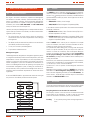
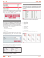
U N I N T E R R U P T I B L E P O W E R S U P P LY ( U P S ) + V O LTA G E S TA B I L I S E R S A N D P O W E R L I N E C O N D I T I O N E R S + S W I T C H M O D E P O W E R S U P P LY + I N D U S T R I A L P O W E R S U P P LY + L I G H T I N G F L O W D I M M E R S TA B I L I S E R S + S TAT I C I N V E R T E R S control center and fimweb for ILUEST+ SICRES user’s manual GENERAL INDEX 1. INTRODUCTION. 1.1. 1.2. 1.2.1. 1.2.2. Gratefulness letter. Using this manual. Used conventions and symbols. For more information and/or help. 2. quality and standard guarantee. 2.1. Management declaration. 2.2. Standard. 2.3. Environment. 3. CONTROL CENTER. OBJECT. 3.1. Synoptic of Iluest+ 3.2. Menus of the application 3.2.1. Measurements 3.2.2. Parameters and Management 3.2.3. KWh 3.2.4. Time zone setting 4. FIMWEB. OBJECT. 4.1. 4.1.1. 4.1.2. 4.1.3. 4.1.4. 4.1.5. Menus of the application Status Time zone setting Parameters and Management Measurements KWh SALICRU 3 1. INTRODUCtioN. 1.1. Gratefulness letter. We would like to thank you in advance for the trust you have placed in us by purchasing this product. Read this instruction manual carefully before starting up the equipment and keep it for any possible future consult that can arise. We remain at you entire disposal for any further information or any query you should wish to make. Yours sincerely. SALICRU The equipment here described can cause important physical damages due to wrong handling. This is why, the installation, maintenance and/or fixing of the here described equipment must be done by our staff or specifically authorised. According to our policy of constant evolution, we reserve the right to modify the specifications in part or in whole without forewarning. All reproduction or third party concession of this manual is prohibited without the previous written authorization of our firm. 1.2.Using this manual. The target of this manual is to give explanations and procedures for the installation and operating of the equipment. This manual has to be read carefully before installing and operating it. Keep this manual for future consults. 1.2.1.Used conventions and symbols. «Warning» symbol. Carefully read the indicated paragraph and take the stated prevention measures. «Danger of electrical discharge» symbol. Pay special attention to it, both in the indication on the equipment and in the paragraph referred to this user’s manual. «Main protective earthing terminal» symbol. Connect the earth cable coming from the installation to this terminal. «Notes of information» symbol. Additional topics that complement the basic procedures. Preservation of the environment: The presence of this symbol in the product or in their associated documentation states that, when its useful life is expired, it will not be disposed together with the domestic residuals. In order to avoid possible damages to the environment, separate this product from other residuals and recycle it suitably. The users can contact with their provider or with the pertinent local authorities to be informed on how and where they can take the product to be recycled and/or disposed correctly. 1.2.2.For more information and/or help. For more information and/or help of the version of your specific unit, request it to our Service and Technical Support (S.T.S.). 4 user’s manual 2.QUALITY AND STANDARD GUARANTEE. 2.1.Management declaration. Our target is the client’s satisfaction, therefore this Management has decided to establish a Quality and Environmental policy, by means of installation a Quality and Environmental Management System that becomes us capable to comply the requirements demanded by the standard ISO 9001:2000 and ISO 14001:2004 and by our Clients and concerned parts too. Likewise, the enterprise Management is committed with the development and improvement of the Quality and Environmental Management System, through: 2.2. Standard. The SICRES product is designed, manufactured and commercialized in accordance with the standard EN ISO 9001 of Quality Assurance. The marking shows the conformity to the EEC Directive (quoted between brackets) by means of the application of the following standards: • 2006/95/EC of Safety of Low Voltage • 2004/108/EC of Electromagnetic Compatibility (EMC). in accordance with the specifications of the harmonized standards. Standards of reference: • IEC/EN 62310-1: Safety. Static Transfer Switch (STS). Part 1: General requirements of safety. • The communication to all the company about the importance of satisfaction both in the client’s requirements and in the legal and regulations • IEC/EN 62310-2: Electromagnetic Compatibility (EMC). Static Transfer Switch (STS). Part 2: General requirements of electromagnetic compatibility (EMC). • The Quality and Environmental Policy diffusion and the fixation of the Quality and Environment targets. When a SICRES card is used as part or component of a complex system or installation, the Generic or Product standards of that installation or specific system must be applied. It is possible that when adding parts, or being under the requirements of a specific standard, all the parts have to be under corrections to assure the conformity with the European Directives and the corresponding national regulations. It is responsibility of the project Manager and/or fitter, the compliance of the standard, providing to the installation all the needed parts to comply the standard. Furthermore, the interference phenomena due to input harmonic currents exists, and although it is not regulated by these standards, it is necessary to correct in some installations. The device is a class C1 product of electromagnetic interference IEC62310-2. Depending on the installation conditions of SICRES, the corrections described in the Electromagnetic Compatibility have or do not have to be done. Regarding the Safety (standard EN 60950-1), for all the versions , should be kept in mind the aspects of the Product detailed in the INSTALLATION section. • To carry out revisions by the Management. • To provide the needed resources. Management agent. The Management has designated as management agent the person in charge about the Quality and Environment department, who with independence of other responsibilities, has the responsibility and authority to assure that the processes of the quality and environmental management system are established and maintained; to inform to the Management about the operating of the quality and environmental management system, including the necessities for the improvement; and to promote the knowledge of the client’s requirements and environmental requirements at all the levels of the organization In the next PROCESS MAP is represented the interaction among all the processes of the Quality and Environmental System: 2.3. continuous improvement process/ management review quality management process environmental management process R & D process technical OFfICe process This product has been designed to respect the environment and has been manufactured in accordance with the standard ISO 14001. Customers: - PRODUCT - SERVICe CustomerS COmMERCIAL process Environment. manufacturing process internal logisitic process Recycling the device at the end of its useful life: Our company commits to use the services of authorised societies and according to the regulations, in order to treat the recovered product at the end of its useful life (contact your distributor). Packing: To recycle the packing, follow the legal regulations in force maintenance process training process Fig. 1. Process map of Quality and environmental system SALICRU 5 3. control center. OBJEcT. The target of this section is to describe the operating and all the different screens of Iluest and Iluest+ equipments in the Control Center of SICRES. 3.1. The top right corner shows the graphic of the ramps. It will be shown the corresponding graphic to the duty cycle of the current day. The graphic will highlight in red colour the current active stretch. In case there were no communication with the equipment, the graphic will be displayed with the label ‘OFF’ in the top part. Synoptic of Iluest+ This form is for consulting only, and there is access to it through the map of units, making double click over one Iluest or Iluest+ unit, the screen shows a summary of all the most significant data of the equipment. This form is divided in several areas, which are are detailed as follows: The top left corner, shows a graphic with the statuses of the unit and their modules. It is used a colour code to symbolize the statuses of the unit and modules: • Grey: There is no communication with the equipment, so the status of the unit and modules can’t be determined. • Green: There is communication and there is not any alarm. The middle part of the form, shows some graphics with the following measurements for all the different stages: • Output voltage. • Output current. • Power. • Red: There is communication and there is an alarm. Next is shown the appearance of the form. Next is shown an example of a module with an alarm: • Load percentage. Tthe lower part of the form, shows other interesting parameters of the equipment: • Type of lamp. • Nominal power. • Start up power. • Saving power 1. • Saving power 2. 6 user’s manual 3.2.1. Measurements From this menu there is access to both the measurements of the equipment and to some graphics of itself. The information is divided in two sections, ‘Measurements’, which shows the information in a tabular way: In the bottom right corner of the screen there are some buttons as shortcuts to the screens ‘Measurements’, ‘Parameters and Management’, ‘KWh’ and ‘Time scheduler’ of the unit: And graphic section, which shows the following graphics: 3.2.Menus of the application Once the access to the application of the Control Center is established, provided that the user has access to it, in the left side there will be displayed a new set of screens under the group ‘Iluest+’, which from this one there is access to all the setting and monitoring forms of the Iluest+ units. Those screens are: • Input voltage • Output voltage • Output current • Cos Phi • Apparent power • Measurements • Active power • Parameters and Management • Reactive power • KWh • Load percentage • Time scheduler Next, it is shown the appearance of the graphic forms: The filtering area is a common element in all the screens. The consult can be done by filtering by ‘Client’, ‘Group’ and ‘Unit’. This filter is showing the Iluest+ units only. Likewise, there is an area with the summary of the consulted unit, where it is shown Client, Group, Unit description, last date of communication and IP address among other data. Next, the different menus of Iluest+ are detailed: SALICRU 7 3.2.2. Parameters and Management From this form there is access to several important data of the unit, if the value allows it , it is possible to set the parameters of the unit. 3.2.4. Time zone setting From this form is possible to set the time scheduler of the unit. The screen has two sections. 3.2.4.1. Time scheduler The displayed data are grouped in the following categories: • Equipment data • Operating status • Time and date • Parameters It is possible to set the ‘Time scheduler’ of Iluest+ from this section. The way to operate is as follows: 1. Select the day to set, it can be any weekday or special one. a. Weekday, select the day to set between Monday to Sunday from listbox. • Digital inputs and outputs Through the button next to value of the measurement, the possible changes already done are saved. The appearance of the form is as follows: b. Special day, select a special day to set between 1 and 10. 3.2.3. KWh From this form there is access to the information of consumptions and energy saving of the unit. This information is divided in two sections, ‘KWh’, which is shown in a tabular way: And the graphic section, where the following graphics are shown: c. Press button ‘Get settings’, the setting of the equipment is consulted for the selected day, and the lower part of the screen shows it. The appearance is the following: • Saving KWh • CO2 emission Likewise there are two counters regarding the energy consumption of the unit. One of them are the KWh saved by the equipment and the other one is the instantaneous saving in CO2 of the equipment. There are two additional counters that make the sum of the same values for all the Iluest+ units of the client. Next, the appearance of the form is shown: 2. In case of a special day, the day and month have to be set. 3. Next, the Operating mode has to be established. It is possible to select between 3 operating modes listed from 0 to 3. Every time that the Operating mode is changed, the graph and different settings of the part change too. 4. Once the operating mode is selected, it is compulsory to select if the Astronomical clock will be used. In case of yes, it will not be possible to set the hour and minutes of turning on/off the unit. 8 user’s manual 5. Lastly the time of status changing has to be selected. Depending on the Operating mode, we will have to set more or less time transitions. When entering a new time, the graphic will show the status transition that we are changing. Next, it is shown the appearance of the form: 6. Additional, and providing that we are forming a normal day, it is possible to copy the configuration that has just be realized to any other day of the week. For it there will be in use the controls that exist by foot of form and it will be selected to what day (s) one must answer the configuration. 3.2.4.2. See the programmation. From this paragraph it is possible to consult the hourly programming. It is possible to consult so much the programming of the normal days as that of the special days. The aspect of the screen is the following one: 3.2.4.3. Astronomical clock This section allows setting the astronomical clock of the unit, it is possible to set several parameters relating to it. The top part of the form is used to set the longitudes and latitudes of main Spanish cities. To do it just select the province and later on the city and press ‘Apply’ to set the preset longitude and latitude: SALICRU 9 4. FIMWEB. OBJECT. The current section has as object to describe the operating and all the screens of the Iluest and Iluest+ units of FIMWeb application. 4.1. Menus of the application Once there is access to FIM web application, there will be a menu in the left side. From this menu there is access to all the setting and monitoring forms. In case that the set unit were Iluest or Iluest+, in section ‘Unit’ there will be new menu options, which are: • Status • Time setting • Parameters and Management • Measurements • KWh Next, it is detailed all the menus of Iluest+. The top right corner shows the graphic of the duty cycle. The graphic shows the corresponding operating mode set for the current day. Also the graphic will highlight, in red colour, the current active stretch. In case there were not any communication with the equipment, the graphic will be displayed with the label ‘OFF’ in the top part. 4.1.1. Status This form is for consulting only, and it shows a summary of all the most significant data of the equipment. Next, it is shown the appearance of the form. The form is divided in several areas, which are detailed as follows: Graphics with measurements, the middle part of the form shows several graphics with the following measurements per each phase: • Output voltage. • Output current. • Power. • Load percentage. In the top left corner there is a graphic with the statuses of the unit and its modules. It is used a code of colours to symbolize the statuses of the unit and modules: • Grey: There is no communication with the equipment, so the status of the unit and modules can’t be determined. • Green: There is communication and there is not any alarm. • Red: There is communication and there is an alarm. 10 user’s manual b. Special day, select a special day to set between 1 and 10. The lower part of the form shows other interesting parameters of the equipment: • Type of lamp. c. Press button ‘Get settings’, the setting of the equipment is consulted for the selected day, and the lower part of the screen shows it. The appearance is the following • Nominal power. • Start up power. • Saving power 1. • Saving power 2. Lastly the lower part of the screen shows a field to enter the number of seconds to refresh the information displayed in the form. If a quantity if seconds is entered and the next check box is activated, the information will be updated every that quantity of seconds automatically. 4.1.2. Time zone setting From this form is possible to alter the time scheduler of the unit. The screen has two sections. 2. In case of a special day, the day and month have to be set. 3. Next, the Operating mode has to be established. It is possible to select between 3 operating modes listed from 0 to 3. Every time that the Operating mode is changed, the graph and different settings of the part change too. 4. Once the operating mode is selected, it is compulsory to select if the Astronomical clock will be used. In case of yes, it will not be possible to set the hour and minutes of turning on/off the unit. 5. Lastly the time of status changing has to be selected. Depending on the Operating mode, we will have to set more or less time transitions. When entering a new time, the graphic will show the status transition that we are changing. 4.1.2.1. Timer From this section is possible to set the time scheduler of the Iluest device. The way to operate is as follows: 1. Select the day to set, it can be a Weekday or Special one. a. Weekday, select the day to set between Monday to Sunday from listbox. SALICRU 6. Additional, and providing that we are forming a normal day, it is possible to copy the configuration that has just be realized to any other day of the week. For it there will be in use the controls that exist by foot of form and it will be selected to what day (s) one must answer the configuration. 11 4.1.2.1. See the programmation. From this paragraph it is possible to consult the hourly programming. It is possible to consult so much the programming of the normal days as that of the special days. The aspect of the screen is the following one: 4.1.3. Parameters and Management From this form there is access to several important data of the unit, if the value allows it, it is possible to set the parameter of the unit. The displayed data are grouped in the following categories: • Equipment Data • Operating status • Time and date • Parameters • Digital inputs and outputs Through the button located in the lower part of the form, it is possible to save the changes that could be done in the values. The appearance of this form is as follows: 4.1.2.2. Astronomical clock This section allows setting the astronomical clock of the unit, it is possible to set several parameters relating to it. The top part of the form is used to set the longitudes and latitudes of main Spanish cities. To do it just select the province and later on the city and press ‘Apply’ to set the preset longitude and latitude: 4.1.4.Measurements From this menu there is access to the measurements of the equipment as well as some graphics of these measurements. The information is divided in two sections, ‘Measurements’, which shows the information in a tabular way: Next, it is shown the appearance of the form: And graphic section, which shows the following graphs: • Input voltage • Output voltage • Output current • Cos Phi • Apparent power • Active power 12 user’s manual • Reactive power • Load percentage Next, it is shown the appearance of the graphic form: 4.1.5. KWh From this form there is access to the consumption of the device and the energy saving of itself. The information is divided in two sections, ‘KWh’, which shows the information in a tabular way: And graphic section, which shows the following ones: • Saving KWh • Emission CO2 Likewise, there two counters relating to energy consumption of the unit, which are the KWh saved by the equipment and the instantaneous saving of CO2 of the equipment. Next, it is shown the appearance of this form: SALICRU 13 U N I N T E R R U P T I B L E P O W E R S U P P LY ( U P S ) + V O LTA G E S TA B I L I S E R S A N D P O W E R L I N E C O N D I T I O N E R S + S W I T C H M O D E P O W E R S U P P LY + I N D U S T R I A L P O W E R S U P P LY + L I G H T I N G F L O W D I M M E R S TA B I L I S E R S + S TAT I C I N V E R T E R S Avda. de la Serra, 100 08460 Palautordera BARCELONA Tel. +34 93 848 24 00 Fax. +34 94 848 11 51 [email protected] Tel. (SST) 902 48 24 01 Fax. (SST) +34 848 22 05 [email protected] SALICRU.COM BRANCHES AND SERVICES and TECHNICAL SUPPORT (STS) MADRID PALMA DE MALLORCA BARCELONA PAMPLONA BADAJOZ SAN SEBASTIAN BILBAO SANTA CRUZ DE TENERIFE GIJON SEVILLE LA CORUÑA VALENCIA LAS PALMAS DE G. CANARIA VALLADOLID MALAGA ZARAGOZA MURCIA SUBSIDARIES FRANCE RUSSIA PORTUGAL CHINA HUNGARY SINGAPORE UNITED KINGDOM MEXICO POLAND URUGUAY GERMANY ECUADOR BELGIUM PERU DENMARK SAUDI ARABIA GREECE ALGERIA HOLLAND EGYPT IRELAND JORDAN NORWAY KUWAIT CZECH REPUBLIC MOROCCO SWEDEN TUNISIA SWITZERLAND KAZAKHSTAN UKRAINE PAKISTAN ARGENTINA PHILIPPINES BRAZIL INDONESIA CHILE MALASYA COLOMBIA THAYLAND Product Range Uninterruptible Power Supplies UPS Voltage Stabilizers and Power Line Conditioners Digital Switch Mode Power Supplies Industrial Power Supplies Lighting Flow Diming - Stabilizers (ILUEST) Static inverters Continuous regulation autotransformers EK794B01 Note: Salicru can give other solutions in power electronics according to the application specifications or technical specifications REST of WORLD