1
YAWL - User Manual
Version 2.1beta
©
2010 The YAWL Foundation
2
Contents
1 The Editor
5
1.1
Launching the YAWL Editor . . . . . . . . . . . . . . . . . . . . . . . . . . . . . . . . . . . .
5
1.2
The YAWL Editor Workspace . . . . . . . . . . . . . . . . . . . . . . . . . . . . . . . . . . . .
6
1.3
Creating Your First Specification . . . . . . . . . . . . . . . . . . . . . . . . . . . . . . . . . .
12
1.4
Changing the Appearance of Your Specification . . . . . . . . . . . . . . . . . . . . . . . . . .
23
1.5
Additional Specification Features . . . . . . . . . . . . . . . . . . . . . . . . . . . . . . . . . .
26
1.6
Connections . . . . . . . . . . . . . . . . . . . . . . . . . . . . . . . . . . . . . . . . . . . . . .
49
1.7
Validating and Saving a Specification . . . . . . . . . . . . . . . . . . . . . . . . . . . . . . . .
52
1.8
Specification Analysis . . . . . . . . . . . . . . . . . . . . . . . . . . . . . . . . . . . . . . . .
54
1.9
Automated task . . . . . . . . . . . . . . . . . . . . . . . . . . . . . . . . . . . . . . . . . . . .
57
1.10 Resource Management (Manual task) . . . . . . . . . . . . . . . . . . . . . . . . . . . . . . . .
59
1.11 Task Timer . . . . . . . . . . . . . . . . . . . . . . . . . . . . . . . . . . . . . . . . . . . . . .
62
1.12 Custom Forms . . . . . . . . . . . . . . . . . . . . . . . . . . . . . . . . . . . . . . . . . . . .
65
1.13 Configurable YAWL . . . . . . . . . . . . . . . . . . . . . . . . . . . . . . . . . . . . . . . . .
66
1.14 Configurable Logging . . . . . . . . . . . . . . . . . . . . . . . . . . . . . . . . . . . . . . . . .
72
1.15 Extended Attributes . . . . . . . . . . . . . . . . . . . . . . . . . . . . . . . . . . . . . . . . .
74
3
4
CONTENTS
Chapter 1
The Editor
Before a workflow model can be executed it must first be defined. This chapter describes the YAWL Editor
(version 2.1), a tool for creating, editing, configuring, validating and analysing workflow specifications. New
users are encouraged to read the chapter sequentially; experienced users may pick-and-choose what they need
from this chapter.
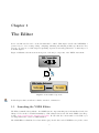
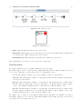
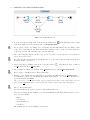
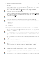
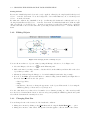
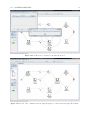
Figure 1.1 illustrates the interactions among some of the major components of the YAWL environment.
Visual process
model
XML
Workflow
specification
API calls
XML over HTTP
Figure 1.1: The YAWL Components
In this chapter, this icon indicates a hands-on method or instruction.
1.1
Launching the YAWL Editor
The Editor is installed along with the other YAWL System components using any of the installers described in
Chapter ??. It can also be installed manually by downloading the latest version from the YAWL SourceForge
website: http://sourceforge.net/projects/yawl/. Be sure that the version number of the Editor you
are using matches the version of YAWL installed.
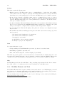
The YAWL Editor is distributed as a Java Archive (jar). Double click on the YAWLEditor2.1.jar file to start
5
6
CHAPTER 1. THE EDITOR
the application (where supported). The YAWL Editor can also be started from a command line or Terminal
prompt:
java –jar YAWLEditor2.1.jar
1.2
The YAWL Editor Workspace
The first time you start the YAWL Editor, you will be presented with a blank canvas, and a prompt in the
Status Bar advising you to open or create specification to begin.
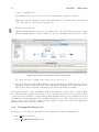
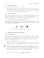
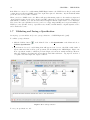
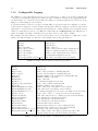
Before you create your first specification, let us take a brief tour of the Editor’s workspace and the elements
within (the use of each element is fully described in later sections). The workspace is shown in Figure 1.2.
Figure 1.2: The YAWL Editor Workspace
1.2. THE YAWL EDITOR WORKSPACE
1.2.1
7
The Toolbar
The Menu Toolbar contains nine groups of buttons to assist you in maintaining your YAWL specification.
The toolbar can be repositioned by dragging the left-hand anchor bar. Each button may be enabled or
disabled at certain times depending on what you are currently doing in the Editor.
Specification Maintenance
This group of buttons provides the standard file options (left to right):
•
Create a new specification;
•
Open an existing specification file. Specification files will have a .yawl extension (or sometimes a .xml
extension, if they are an ‘engine’ file created with a pre-2.0 Editor version);
•
Import a specification file created with a pre-2.0 version of the Editor. These files have a .ywl extension.
•
Save the currently loaded specification to file. For newly created specifications, this behaves the same
as Save As;
•
Save As a new file name;
•
Close the loaded specification. If there are any unsaved changes, you will be prompted to save the file
first before closing.
Specification Verification & Analysis
The first of these two buttons allows you to validate your specification against YAWL syntax and semantics,
while the second allows you to analyse your specification for deadlocks and other issues.
Net Maintenance
Each workflow specification consists of one or more nets. You can use these buttons to add a new Net to or
remove an existing Net from your specification.
Edit Options
This group of buttons provides the standard Undo and Redo options as well as the option to delete the
currently selected object(s).
8
CHAPTER 1. THE EDITOR
Alignment Options
These buttons can be used to assist with the alignment of objects within your specification, when multiple
objects have been selected. Left-to-right, they allow you to align selected objects based on:
•
top edges;
•
centres horizontally;
•
bottom edges;
•
left sides;
•
centres vertically;
•
right sides
The first selected object is used as the reference to align the other objects to.
Object Sizes
To increase or decrease the size of an object or objects within your specification, select the object(s) and
then use these buttons.
Cancellation Sets
These buttons allow you to include in and/or exclude elements from the cancellation set of a task.
Process Configuration
These buttons allow you to preview (left) and apply (right) process configuration settings for a net.
Zoom Options
These buttons allow you to apply zoom functionality to the currently selected net. From left-to-right, reset
the zoom to the actual size, zoom the entire net out, zoom the entire net in, and zoom into the currently
selected net elements.
1.2.2
The Menubar
This section provides a brief overview of the YAWL Menus located along the top of the YAWL Editor. The
majority of menu choices are also available via the menu toolbar.
1.2. THE YAWL EDITOR WORKSPACE
9
Specification
In addition to the Specification Maintenance, Verification and Analysis toolbar items, this menu also contains
these sub-items:
•
Open Recent: show a list of the eight most recent specifications loaded or saved in the Editor, so that
one can be selected to be opened, saving the trouble of navigating to it via the file open dialog. If you
hover the mouse over a listed file for a moment, a tip will appear showing the file’s full path;
•
Print: prints the entire loaded specification (graphically);
•
Update the Specification Properties: such as specification name, author, description and so on;
•
Update Datatype Definitions: where you can define your own data types to be used in the specification.
Net
In addition to the Net Maintenance toolbar items, this menu also contains these sub-items:
•
Set Starting Net: for specifications containing several nets, this item allows you to specify which of
them is the starting net (i.e. the net that begins execution of the workflow instance);
•
Update Net Detail: shows a dialog where you can set the name of the net, and create/update/remove
net-level variables;
•
Export to PNG Image: saves a graphical image of the net to a file;
•
Net Background Colour: set the background colour of the selected net;
•
Net Background Image: set the background image of the selected net;
•
Print Net: prints the currently selected net (graphically).
•
Process Configuration: a sub-menu containing three items:
– Preview Process Configuration: shows a preview of the effect of the current process configuration
settings;
– Apply Process Configuration: applies the current configuration settings to the net, so that only
the configured components remain;
– Check Configuration Correctness: analyses the net to check the correctness of configuration settings (requires that the ‘wendy’ tool is available).
Edit
In addition to the Edit Options toolbar items, this menu also contains sub-items to Cut, Copy and Paste
objects to/from the canvas.
Elements
This menu contains the Alignment Options, Object Sizes and Cancellation Set toolbar item sets. You can
also set the fill colour for all selected tasks and conditions using this menu.
10
CHAPTER 1. THE EDITOR
Settings
This menu contains the following items:
•
Engine Connection: The Editor must connect to a running Engine to obtain a list of the available
services that a task can be assigned to (amongst other things discussed in later sections). This menu
item allows you to set the parameters for a connection to the Engine and to proceed with a connection.
•
Resource Service Connection: The Editor must connect to a running Resource Service to obtain a
list of the available resources that task can be allocated to (amongst other things discussed in later
sections). This menu item allows you to set the parameters for a connection to the Resource Service
and to proceed with a connection.
•
Specification Analysis: This item will display a dialog where various verification and analysis techniques
may be chosen. In addition, if the wofyawl analysis utility is available, the configuration dialog will
allow process designers to configure and use wofyawl for additional specification analysis1 .
•
Process Configuration: This item will display a dialog where the desired process configuration settings
may be chosen.
•
External File Paths: This item will display a dialog where the disk locations of the following components
may be specified:
–
–
–
–
–
User-defined extended attributes for decompositions;
User-defined extended attributes for variables;
User-supplied icons for tasks;
the WofYAWL tool (for specification analysis);
the Wendy tool (for process configuration).
View
You can use this menu to toggle:
•
Tooltips, which provide useful hints when your mouse is positioned over various items;
•
Anti-aliasing of graphical components; and
•
Grid on the canvas background – useful for aligning objects visually.
This menu also provides options to set the font size used for element labels, the default background colour
for nets, and the default background colour for elements (i.e. tasks and conditions). Finally, it shows a list
of all the nets of the loaded specification, allowing the selection of one from those available for editing.
Help
The Help Menu provides an “About the Editor” dialog, describing components used in the editor’s construction, a list of source code contributors, and the version and build date of the Editor in use.
1.2.3
Workflow Elements and Tools
The Workflow Elements and Tools panel contains seven selectable buttons – five YAWL language icons and
two selection tools – that assist with creation, selection and positioning of objects within your specification.
This panel is also accessible by right-clicking on any blank area of the canvas.
Once an element is selected, it is possible to place objects of that type on the canvas by left-clicking the
mouse button at the desired location.
1 Only
available when installed in a Windows environment.
1.2. THE YAWL EDITOR WORKSPACE
11
Atomic Task
Select this button to create an Atomic Task, which represents a single task to be performed, usually by a
human participant or an external application or service.
Composite Task
Select this button to create a Composite Task, which is a container for another YAWL (sub) Net - with its
own set of YAWL elements constrained by the same syntax.
Multiple Instance Atomic Task
Select this button to create a Multiple Instance Atomic Task, which allows you to run multiple instances of
a task concurrently.
Multiple Instance Composite Tasks
Select this button to create a Multiple Instance Composite Task, which allows you to run multiple instances
of a composite task concurrently.
Condition
Select this button to create a Condition, which is a way to represent state for the Net.
Marquee Selection
Select this button to activate the Marquee Selector, which will allow you to select individual or multiple
objects by clicking and dragging the left mouse button. Note: you cannot create flows (arrows between
tasks) while the Marquee Selector is selected.
Drag Net Window
Select this button to drag the visible window of a net around that net.
1.2.4
Other Components
The Canvas
The Canvas is where elements are placed to create and modify a workflow specification.
12
CHAPTER 1. THE EDITOR
Task Icons Panel
This panel shows a set of icons that can be selected and placed on the tasks of your specification to add
visual cues that aid in the understanding of your models by others. The Editor comes with a standard set
of icons, and you may also provide your own icons and access them via this panel. Note that the icons are
grouped for ease-of-use only; you are not limited in how you actually use the icons in your model. Any icons
displayed have no bearing on how the model executes at runtime.
Decorations Panel
The Decorations panel provides a set of decorator types that may be attached to a task. You can select the
type of decorator, what edge it is to be positioned on the task and choose a colour to use for each decoration.
Notes and Problem Panel
This panel consists of two tabs:
•
On the Notes pane, you can add freeform text to accompany the selected task or condition. Any text
entered is accessible only at design time;
•
The Problems pane will list problems or messages that may occur while you are building your model,
when you validate it or when you analyse it.
Status Bar
The Status Bar consists of three parts:
•
On the left are two icons that indicate whether there are currently valid connections to the Engine and
the Resource Service (required for certain design activities discussed later in this chapter). A connection
will show a green indicator, a disconnection as a red indicator;
•
Next there is a status message area that provides useful contextual hints throughout the creation of
your specification;
•
On the right is a progress bar, which shows the progress of various events at different times.
1.3
Creating Your First Specification
Overview
This section will lead you through the process of creating a YAWL specification from beginning to end,
through a series of brief lessons following a scenario.
You can either follow all the instructions including the scenario provided, from beginning to end, or skip
straight to the section that you are interested in and follow the instructions.
Look for the student icon next to the instructions for specific details of the scenario.
The Scenario
The scenario that we will be following throughout this section is the workflow of a student who has just
completed their secondary study and is now looking to start their career. The scenario will follow the path of
a student who either enrols in a University to complete their tertiary education, or undertakes private study
that will eventually lead them to getting a job and starting their new career.
1.3. CREATING YOUR FIRST SPECIFICATION
1.3.1
13
Creating Your First Specification
1. Click on the Create a New Specification button,
, at the top left of the Menu Toolbar, or click on
Specification in the Menu and choose Create Specification. This will create a blank Net called
“New Net 1” which will be, by default, the starting net of the workflow. For details on selecting a
starting net, consult Section 1.3.6.
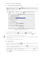
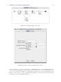
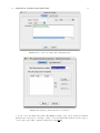
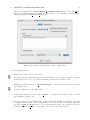
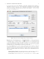
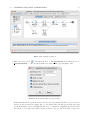
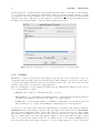
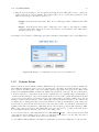
2. Click on Specification in the main Menu and choose Update Specification Properties. A screen
as per Figure 1.3 will appear. Alter the specification’s properties as you feel appropriate.
Figure 1.3: Specification Properties Dialog
3. Rename this Net by clicking on the Net Menu and choosing Update Net Detail.
4. Enter the new name of the Net in the “Decomposition Label” field, then click the Done button.
Decomposition Variables will be explained later in Section 1.5.3.
Change the name of the Net in the Decomposition Label, to “My Career”. This Net will be the primary
net for our scenario.
5. You are now ready to start drawing your specification.
1.3.2
Atomic Tasks
1. Click on the “Add an Atomic Task” button,
, in the Workflow Elements Panel, or right click in an
empty area of the canvas, and choose Atomic Task.
2. Position your mouse just to the right of the Input Condition (the
button once to place an Atomic Task.
symbol), and click the left mouse
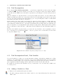
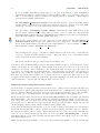
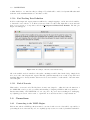
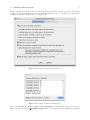
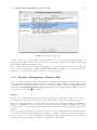
3. Set the decomposition of this task by right clicking on the Atomic Task and choosing Select Task
Decomposition. You should see a dialog as per Figure 1.4.
4. Press the Create. . . button, and in the following Update Task Decomposition dialog, enter the decomposition’s label.
14
CHAPTER 1. THE EDITOR
Figure 1.4: The “Select Task Decomposition” dialog
See Section 1.5.5 for a full explanation of this dialog’s features.
Set the label to “Begin My Career”, and click the Done button.
5. Note that by default, a task takes on the label of the decomposition that it is associated with (several
tasks are allowed to share the same decomposition). Once you’ve created your task, you are free to
relabel the task to whatever you like. This can be done by right-clicking on the task and choosing Set
Label. . . from the pop-up menu. This will not change the name of the decomposition with which the
task is associated.
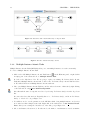
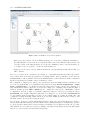
6. Connect the Input Condition to your Atomic Task, as shown in Figure 1.5, by finding the flow connectors
that appear as small blue boxes as you hover your mouse over the sides of the objects. Hold the left
mouse button down over a flow connector and draw a line by dragging the mouse from the flow connector
on the Input Condition to the one on the Atomic Task (which will appear when the mouse hovers over
the edges of the task). The editor will only show a connection point if it is valid to draw a flow
connection between the objects. The directed arc (arrow) between two objects is referred to as a flow
Figure 1.5: An established flow relation
relation, or most often simply a flow – it shows the ‘flow’ of execution from one object in the net to
the next. That’s it! Your Atomic Task is set.
Repeat the process for the following Atomic Tasks in order: Go to University, Get A Job, Career
Started.
Link the ‘Career Started’ task to the Output Condition (the
symbol), as per Figure 1.6.
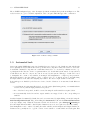
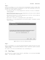
7. Finally check the validity of specification by clicking on the Validate Specification button,
, in the
Menu Toolbar or click on Specification in the Menu and choose Validate Specification. If all things
are going to plan, then you should receive a confirmation saying that there were no errors detected.
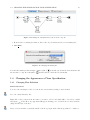
Task Indicators
Task indicators are mini-icons that appear across the top of a task to provide a visual cue regarding settings
that have been applied to the task. An example of a task with all three available indicators is shown in
Figure 1.7.
The three task indicators (left to right in Figure 1.7) are:
1.3. CREATING YOUR FIRST SPECIFICATION
15
Figure 1.6: The “My Career” Net
Figure 1.7: Task Indicators
•
Timer: This task has had a timer set (see Section 1.11).
•
Automated: This task has been set as automated (see Section 1.9). If this automated task also has
a codelet specified, it will be filled green (see Section 1.9.1).
•
Cancellation Set: This task has had a cancellation set defined (see Section 1.5.1).
These task indicators are rendered on top of any icons set for the task.
Task Decoration
Decorating a task is the process of adding a split and/or join to the task.
By adding a split decorator to a task, you are specifying that when the task completes, it will be succeeded
by one or more tasks. Here are the possible choices for a task’s split decorator:
•
No split: The task has no split decorator, and so will have exactly one outgoing flow;
•
AND split: The task may have a number of outgoing flows; when the task completes, it will activate
each and every outgoing flow;
•
XOR split: The task may have a number of outgoing flows, each with an associated condition; when
the task completes, it will activate exactly one outgoing flow – the first that has its condition evaluate
to true, or the designated default flow if none of the other flow conditions evaluate to true;
•
OR split: The task may have a number of outgoing flows, each with an associated condition; when
the task completes, it will activate each outgoing flow that has its condition evaluate to true, or the
designated default flow if none of the other flows evaluate to true;
By adding a join to a task, you are specifying at what point the task will become available for execution
through the completion of one or more preceding tasks flowing into it (depending on the type of join). Below
are possible choices for a task’s join decorator:
16
CHAPTER 1. THE EDITOR
•
No join: The task has no join decorator, and so will have exactly one incoming flow;
•
AND join: The task will activate only after each and every incoming flow is activated (through the
completion of the task at the other end of each flow);
•
XOR join: The task will activate as soon as one incoming flow is activated (through the completion of
the task at the other end of the flow);
•
OR join: The task will activate only after each and every incoming flow that can possibly be activated
has activated. Basically this means the completion of each and every task at the other end of a flow
leading into the OR-join that has started or may possibly start at some future time. More on the
OR-join in later sections.
For more detailed information on join and split types, please consult the YAWL technical papers on the YAWL
website.
Creating Splits and Joins
To create a split or join:
1. Select a task. When a single task is selected the Decorator panel will appear with two tabs that allow
you to decorate a task with a split and/or join. You can also choose a fill-colour to help visually
differentiate splits from joins with the expanded colour palette.
2. Choose the required split or join and the orientation (which edge of the task to attach the decoration
to) for the split or join to appear.
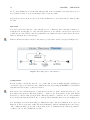
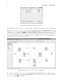
In our example, select the “Begin My Career” task and, in the Decorator panel, select an XOR split.
Then set the orientation to eastern edge of the task, as per Figure 1.8.
Create a new Atomic task called “Do Private Study”. This task will represent those students that
choose not to go to University.
Finally, select your “Get A Job” task and decorate it with an XOR join. Then set the orientation of
the join to the western edge of this task.
3. Split and Join decorators allow you to connect several Flow Relations from and to your task respectively.
Create a flow relation from “Begin My Career” to “Do Private Study”, then create another flow relation
from “Do Private Study” to “Get A Job”, as per Figure 1.8.
4. Don’t forget to check the validity of your specification.
Hint: If you are having trouble with positioning your tasks, the alignment tools are a big help.
When “Begin My Career” has been completed, a choice must be made on which of the two tasks (“Go To
University” or “Do Private Study”) will be followed (XOR Split). How that choice is made will be explained
a little later. “Get a Job” will become available after the completion of the task selected at the point of the
XOR split.
Composite Tasks
1. Composite tasks are placeholders for other sub-nets. That is, you can create another workflow in a
separate Net, which is represented in the first net by the composite task. When a composite task
is activated, control branches to the sub-net; when the sub-net completes, control passes back to the
parent net.
1.3. CREATING YOUR FIRST SPECIFICATION
17
Figure 1.8: XOR Split and Join
2. To create a Composite Task: click on the Composite Task button,
click on an empty part of the canvas and choose Composite Task.
, in the Elements panel or right
We are going to replace our existing “Go to University” Atomic Task with a Composite Task, so click
on the “Go to University Atomic Task” and click the trash bin on the toolbar or press the Delete key
on the keyboard. We will add in the new composite task next.
3. Place your Composite Task in your Net. Tip: use the arrow keys on your keyboard to move/adjust the
task to the desired location.
Reconnect the Flow Relations from “Begin My Career” to the new Composite Task, and from new
Composite Task to “Get a Job”.
4. Create a new Net by clicking on the Create a New Net button,
the Net Menu and choose Create Net.
, on the Menu Toolbar, or click on
5. Choose a name for this Net by clicking on the Net Menu and choosing Update Net Detail.
We are going to call this new Net “Attend University”.
6. Return to your original Net and right click on your Composite Task and choose Unfold to net. . . .
You will then be given a drop-down list with all the Nets available – choose the Net this task is to
represent and then click Done.
Tip: you can also combine the last three steps by simply right clicking on the newly added composite
task, selecting Unfold to net. . . , then clicking the “Create” button in the dialog that appears.
Choose “Attend University”.
You can now fill out the detail of your new ”Attend University” Net.
Create the following Atomic Tasks in order and then link them with Flow Relations and don’t forget to check for validity:
•
•
•
•
Enrol
Do Subjects
Pass All Subjects
Get Degree
The resulting nets are shown in Figures 1.9 and 1.10.
18
CHAPTER 1. THE EDITOR
Figure 1.9: Parent net with “Attend University” Composite Task
Figure 1.10: The “Attend University” sub-net
1.3.3
Multiple Instance Atomic Tasks
Multiple Instance Atomic Tasks (MI Tasks) allow you to run multiple instances of a task concurrently.
To create a Multiple Instance Atomic Task:
1. Click on the Add Multiple Instance Atomic Task button,
, in the Elements panel or right click in
an empty part of the canvas and choose Multiple Atomic Task.
Go back to the “My Career” Net. We are going to replace our existing “Do Private Study” Atomic
Task with a Multiple Instance Atomic task, so click on the “Do Private Study” Atomic Task and delete
it. We will add in the new Multiple Instance Atomic task next.
2. Place your Multiple Instance Atomic Task in your Net and set the name of this task by right clicking
on the task and choosing Select Task Decomposition.
Give this task the same decomposition as before by selecting “Do Private Study” from the drop-down
list.
Reconnect the flow relations from “Begin My Career” to “Do Private Study”, and from “Do Private
Study” to “Get A Job”, as per Figure 1.11.
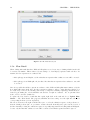
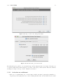
3. You will now need to set the parameters of the MI Task, which, being multiple instance, needs a few
more values set than a simple atomic task. Right click on the task and choose Set Instance Detail.
Ensure that you are viewing the “Bounds” tab of the dialog, as per Figure 1.12.
4. Choose the Instance Creation mode. In either mode, the number of task instances created at runtime
1.3. CREATING YOUR FIRST SPECIFICATION
19
Figure 1.11: Adding a Multiple Atomic Task
Figure 1.12: Instance Bounds on Multiple Instance Tasks
for the task will be between the values given for “Minimum Instances” and “Maximum Instances”.
Static mode means the number of task instances started cannot vary once the task is activated. Dynamic mode means the same number of task instances (as static mode) are started initially, but new
instances of the task may be started dynamically at runtime (i.e. after task execution has begun), up
to the value entered in “Maximum Instances”.
20
CHAPTER 1. THE EDITOR
Set the Instance Creation type to “Static”.
5. Set the Minimum Instances value. This is the minimum number of instances of this task that will be
started when the task is activated.
Set the Minimum Instances to 5.
6. Set the Maximum Instances value. This is the maximum number of instances of this task that can be
created from this task.
Set the Maximum Instances to 100.
7. Set the Continuation Threshold value. The moment all task instances created have completed, or if the
number of instance created exceeds the Continuation Threshold, the number specified for the Continuation Threshold have completed, the multiple instance task itself will be considered complete, and will
trigger relevant outgoing flow relations from this task.
Set the Continuation Threshold to 50.
8. Click Done.
With the values set in the scenario, it has been specified that the Do Private Study task can have a maximum
of 100 instances created, a minimum of five instances will be created, and once 50 instances (or all those
started if less than 50) have completed, the outgoing flow relation to ‘’Get A Job” will trigger.
We will revisit the setting of parameters for multiple instance tasks, in particular the details of the “Queries”
tab of the Multiple Instance Detail dialog, in Section 1.5.9, after the basics of queries have been introduced.
1.3.4
Multiple Instance Composite Tasks
Multiple Instance Composite Tasks allow you to run multiple instances of the sub-net represented by a
multiple composite task, concurrently.
To create a Multiple Composite Task:
1. Click on the Add Multiple Composite Task button,
, in the Elements panel or right click in an empty
part of the canvas and choose Multiple Composite Task.
Go to the “My Career” Net. We are going to replace our existing “Do Private Study” Multiple Instance
Task, with a Multiple Composite task, so click on the “Do Private Study” Task and delete it. We will
add in the new Multiple Composite task next.
2. Place your Multiple Composite Task in your Net.
Reconnect the Flow Relations from “Begin My Career” to the new Multiple Composite Task, and from
the new Multiple Composite Task to “Get a Job”.
3. You will now need to set the parameters of the Multiple Composite Task, in the same manner as those
set previously for the Multiple Atomic Task. Right click on the task and choose Set Instance Detail.
Set the Minimum Instances to 5, the Maximum Instances to 100, the Continuation Threshold to 50,
and the Instance Creation type to “Static”.
1.3. CREATING YOUR FIRST SPECIFICATION
21
4. Click Done.
5. Create a new Net by clicking on the Create a new Net button,
Net in the Menu and choose Create Net.
, on the Menu Toolbar, or click on
6. Give the new Net a name by clicking on the Net Menu and choosing Update Net Detail.
We are going to call this new Net “Study Privately”.
7. Return to your original Net and right click on your Multiple Composite Task and choose Unfold to
Net. You will then be given a drop-down list with all the Nets Available – choose the Net for this task
to initiate and then click Done.
Choose “Study Privately”.
8. You can now complete your new “Study Privately” Net represented by your Composite Task.
Create the following Atomic Tasks in order and then link them with Flow Relations as per Figure 1.13:
1.3.5
•
Read a Book
•
Feel Smarter
Conditions
Conditions represent states of the workflow and can be located in-between tasks. To create a Condition:
1. Click on the Add a Condition button,
canvas and choose Condition.
, in the Elements panel or right click on an empty part of the
Go to the “Study Privately” Net. We are going to place a loop Condition after the Read a Book atomic
task, to determine whether we gained any knowledge from the book. We will add the new Condition
next.
2. Place your Condition in your Net and set the name by right clicking on the Condition and choosing
Set Label.
Call this Condition “Knowledge Gained?”.
3. Now link to the Condition to the tasks of the net using flow relations.
Select the flow relation between the Read a Book atomic task and the Feel Smarter Atomic Task and
delete it.
Create a flow relation from the “Read A Book” task to the “Knowledge Gained?” condition.
4. Create a flow relation from your condition to a task.
Set the flow relation from the “Knowledge Gained?” condition to “Feel Smarter” atomic task.
5. Create another flow relation from your condition to another task to signify the two possible flows from
the condition.
Before we create our second flow relation from our condition, first create another atomic task and call
22
CHAPTER 1. THE EDITOR
it “Look for An Easier Book”.
Add an XOR join decoration to the “Read a Book” task, with the orientation being West.
Finally create the Flow Relation from the “Knowledge Gained?” condition back to the XOR join
of the “Read A Book” atomic task, as per Figure 1.13.
6. Validate your specification.
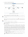
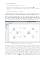
Validation should fail and report errors as per Figure 1.13. The problem here is that the “Study
Privately” multiple instance composite task needs to have more information specified for it to be valid.
Figure 1.13: Validation with unfinished Multiple-Instance Tasks
For setting data detail of multiple-instance tasks, please see Section 1.5.9.
7. Remove the “Study Privately” multiple-instance composite task and replace it with an atomic composite
task using the same decomposition, and re-drawing flows from “Begin My Career” and to “Get A Job”
tasks. Your updated net should look like Figure 1.14, and should validate successfully.
The Knowledge Gained? condition in Figure 1.13 shows an example of a Deferred Choice construct. When
the condition is reached during execution of the process, both of its outgoing flows are activated (note that a
condition may have any number of outgoing flows). This results in both the “Look for an Easier Book” and
“Feel Smarter” tasks appearing in the user’s worklist, allowing the user to make a (deferred) choice between
the two. As soon as the user chooses the appropriate task for execution, the other task is immediately
withdrawn and is removed from the worklist.
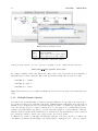
1.3.6
Changing the Starting Net
At any stage you can change the Starting Net of the specification. To change the Starting Net:
1. Select Net from the Menu.
2. Choose Set Starting Net (Figure 1.15).
1.4. CHANGING THE APPEARANCE OF YOUR SPECIFICATION
23
Figure 1.14: Making the “Study Privately” task an atomic composite
3. From the Choose Starting Net window, click on the drop-down list and select a new starting Net.
4. Click Done.
Figure 1.15: Changing the Starting Net
Note that the starting net has an input condition symbol,
sub-nets have a composite task symbol,
1.4
1.4.1
, in its title tab, and in the View menu list. All
, in their title tab, and in the View menu list.
Changing the Appearance of Your Specification
Changing Flow Relations
Bends and Curves
You can control and improve the look of the flows between tasks by adding “bends” in them.
Go to the “Study Privately” Net.
Right click on the position in the flow where you want to add a bend, which will be denoted by a small
, in the Flow. A popup menu will appear, allowing you to add and remove bends, as well as
blue square,
change the line style of the flow.
Create a bend somewhere towards the middle of the flow going from the “Knowledge Gained?” condition to
24
CHAPTER 1. THE EDITOR
the “Look for an Easier Book” atomic task. Then left click on the bend marker created and drag it out to a
more desirable location. You can add as many bends to a flow as you like.
Repeat the process for the flow between “Look For an Easier Book” and “Read A Book” tasks (see Figure 1.16).
Relocation
You can reconnect flow relations to other elements of a net, or different points on the same element by selecting the flow, and dragging one of its connecting ends from one net element to another. If a connection is
possible at some other element, connection points will become visible as described earlier. Release the mouse
button to attach the flow to its new home.
Take the current flow relation, and move it from the top of the task to its side, as depicted in Figure 1.16.
Figure 1.16: Adding bends to a Flow Relation
Adding Labels
It is also possible to add labels to flows. To do so, double click on a flow. A small text input box will appear
over the flow. Type your desired text, and commit the flow label by pressing the ENTER key. You may then
drag that flow label around to position it as desired.
Take the two flow relations that have recently had bends added to them. Attach the label yes to the
flow relation going from the “Knowledge Gained?” condition to the “Feel Smarter” atomic task. Attach
the label no to the flow relation going from the “Knowledge Gained?” condition to the “Look for an Easier
Book” atomic task. Drag the labels about to a desired position, much like what’s been done in Figure 1.16.
Note that Figure 1.17 shows flows using two different line styles. The flow running from “Look for an
Easier Book” has been given the “spline” line style in this figure, while the remaining flows are all “orthogonal”, resulting in sharp edged bends on flows, such as the one running from the “Knowledge Gained?”
condition to the “Look for an Easier Book” task.
1.4. CHANGING THE APPEARANCE OF YOUR SPECIFICATION
25
Setting Colours
For nets, the default background colour can be set (i.e. applied to all nets) by choosing Default Net Background
Colour. . . from the View menu. To set the background colour of individual nets, choose Net Background
Colour. . . from the Net menu.
For tasks and conditions, the default fill colour (i.e. for all newly added tasks and conditions) can be set by
choosing Default Element Fill Colour. . . from the View menu. For individual tasks and conditions, right
click on it then choose Set Fill Colour. . . from the popup menu. Several selected tasks and/or conditions
can have their fill colour set at the same time by choosing Set Selected Fill Colour. . . from the Elements
menu.
1.4.2
Editing Objects
Figure 1.17: Changing the Size of Multiple Objects
You can edit more than one object at a time by using the Marquee Selection tool. See Figure 1.17.
1. Select the Marquee Selection tool,
, from the Elements panel.
2. Click on the first object that you want to edit, then hold down the shift key and then click on the other
objects that you want to edit.
3. Alternately, click and drag the Marquee tool to include multiple items in the drag rectangle.
4. Now choose the Edit option from the Menu or continue holding down the shift key and right click on
the mouse button. Below are the edit options:
•
•
•
Cut, Copy, Delete;
Align;
Size Increase / Decrease to change the appearance of the objects. This can also be done using the
CTRL key plus Up or Down arrow on your keyboard.
Note also, that whenever you have selected a number of net elements, pressing one of the arrow keys will
move the selected elements in the direction of the arrow key, and pressing the CTRL key plus the A key will
select all the elements in the currently selected net.
1.4.3
Changing Font Size
You can change the size of the font used to label tasks and conditions.
1. Change the font size by clicking on the View Menu and choosing the Label Font Size. . . option.
2. Change the font size to that desired. The specified font size applies to all text drawn on the canvas.
26
CHAPTER 1. THE EDITOR
1.4.4
Changing Task Icons
You can add or change the icon that is shown on atomic tasks.
1. Select any single atomic task in your workflow. The palette will expand to include a task icon tree,
depicted in Figure 1.13, where you can an icon from the tree to the task. You are free to assign any
icon. Icons have no runtime effect on the engine, and are provided simply to make specifications more
easily understood by people looking at the specification in the editor.
1.4.5
Using Custom Icons
Workflow designers can plug in and use their own icons for specification design. Icons must be of the PNG
file format, and be a maximum of 24 × 24 pixels to render properly within editor task boundaries.
The editor will load user-supplied task icons from the location specified for them in the Settings...External
File Paths dialog (see Figure ??); if never specified, the location defaults to the directory:
<editor_installation_path>/YAWLEditorPlugins/TaskIcons
and if found adds them into the plugin branch of the task icon tree widget of the editor’s palette. Subdirectories are supported, and will form new sub-trees of the same name when the plugin sub-tree is being
created. If an icon cannot be found that was previously used for a specification, a special “broken” icon will
render in its place, as depicted in Figure 1.18.
Figure 1.18: A task specifying an icon that the editor cannot locate
1.5
Additional Specification Features
1.5.1
Cancellation Sets
Cancellation Sets allow you to nominate any number of tasks, conditions and/or flow relations (which, when
they join two tasks directly, contain an implicit condition that is not visible on the net) for cancellation,
upon the completion of a specified task. That is, once a specified task has completed execution in a workflow
instance, all other net elements within that task’s nominated cancellation set (if any) are deactivated.
To create a Cancellation Set for a task:
1. First select the task that will initiate the Cancellation Set.
2. Right-click on the task, then choose View Cancellation Set from the context menu. The task will
be fill with a grey colour to indicate that this is the task that ‘owns’ the cancellation set currently on
view.
Create the “Purchase Book” specification as shown in Figure 1.19. In this example, we are going to
purchase a book by placing an order with three different sellers; as soon as the first seller fills the order,
we want to cancel the other two orders. To achieve this, we create a cancellation set for each “Order”
task that includes the other two “Order” tasks. We will step through creating a cancellation set for
the “Order from Amazon” task – the other two are created in a similar manner.
Right-click on “Order from Amazon” and choose View Cancellation Set.
1.5. ADDITIONAL SPECIFICATION FEATURES
27
Figure 1.19: The Purchase Book specification
3. Next, choose a task, condition or flow (and thus an implicit condition) to add to the Cancellation Set.
Hold down the shift key to select more than one object for cancellation.
Select the “Order from Booktopia” and “Order from Bookfinder” tasks, and the flow relation preceding
each of them.
4. Click on the Add Selected Items to Visible Cancellation Set button,
, on the Menu Toolbar. Items
will be given a red border to indicate they belong to the cancellation set of the grey-filled task (see
Figure 1.20).
Add the selected tasks and flow relations to the cancellation set.
5. Once you have established the cancellation set, you can right-click on the cancellable task and reselect
View Cancellation Set to toggle off the cancellation set view.
Notes about Cancellation Sets:
•
In the example in Figure 1.20, notice that there is an AND-split decorating the “Get Book Details”
task, but the “Pay” task has an XOR-join. This is because we know that when one of the “Order” tasks
completes, the other two will be cancelled, so only one incoming flow to the “Pay” task will activate.
Since we want the process to complete, we must add the join type that will activate the task when a
single incoming flow activates: the XOR-join. If an AND-join had been used here, it would wait until
all three incoming flows were activated, which in this case is never going to happen, and would result
in the deadlock of the workflow instance. However, without the careful setting of cancellation sets for
all three intermediate tasks, the net would represent an example of an unsound net, which basically
means the net may complete while there were still active tasks within it. Great care needs to be taken
when mixing split and join types, and when defining cancellation sets, so that the execution of the net
behaves precisely as intended.
•
A Cancellation Set that has been created will remain in the specification, regardless of whether you
have the View Cancellation Set option ticked.
•
You can create multiple Cancellation Sets in your workflow, by selecting another task and choosing the
View Cancellation Set option. Only one cancellation set may be viewed at any one time.
28
CHAPTER 1. THE EDITOR
Figure 1.20: A Cancellation Set specified for the ‘Order from Amazon’ task
•
All flows leading to or from (explicit) conditions are not valid cancellation set members. Neither are
the Input and Output conditions. The editor will ignore them if you select them for inclusion in a
task’s cancellation set.
•
A task may be included as a member of its own cancellation set.
•
The reason for including preceding flows of a task in a cancellation set is this: If a flow relation connects
two tasks directly, then it is said to contain an implicit condition. If there is a condition object in the
model between two tasks, so that the connection is task - flow - condition - flow - task (for example, the
“Knowledge Gained?” condition in Figure 1.16), it is said to be an explicit condition. In either case,
when a task completes, it passes ‘control’ to the condition preceding the next task in the flow. When
the next task is started, it takes ‘control’ from its preceding condition (whether implicit or explicit).
If there is a chance that the tasks in a cancellation set may not have started when the owner task of
the set completes, then cancelling those tasks will have no effect – it is their preceding conditions that
have ‘control’ and so they are the elements that must be cancelled. By including both tasks and their
preceding conditions, we are ensuring that the desired cancellation will occur, regardless of whether the
tasks in the set are currently executing or not.
To remove an element from a task’s Cancellation Set:
1. First, make sure you have the View Cancellation Set option ticked for the task. If it isn’t ticked,
select the task that has the Cancellation Set, right-click, then choose View Cancellation Set.
2. Select the element for removal.
3. Click on the Remove Selected Items from Visible Cancellation Set button,
1.5.2
, on the Menu Toolbar.
Data Type Definitions
YAWL uses XML Schema to define data documents that are passed from net to task and back during the
life of a workflow instance. There are over 40 simple XML Schema data types (string, integer, boolean, etc.),
all of which are supported by YAWL.
User-defined data types are also supported, by allowing for the definition of XML Schema complex types,
which are added to a specification and then may be used to define variables based on those types. To define
a new complex type for a specification:
1.5. ADDITIONAL SPECIFICATION FEATURES
29
1. Select Update Data Type Definitions from the Specification Menu.
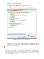
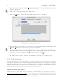
2. Enter your XML Schema Data Type Definition into the dialog box. (See Figure 1.21).
Figure 1.21: Adding the “Geek” complex data type
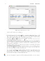
3. If the definition text is green, your new data type is a valid definition and may be used for defining
Net or Task variables in your specification. If the text is red, there is something wrong with your data
type definition, and the data type will not be available. When the text is red, the split-pane will reveal
a table listing parse errors that were collected when determining the validity of the text supplied. An
example of this is shown in Figure 1.22.
Open the Data Type Definitions dialog and type in the XML text that appears in Figure 1.21.
The above example creates a complex data type called “Geek” that has two separate sub-components, “Name”
and “Salary” of type “string” and “double” respectively. Types called ‘Book’ and ‘Booklist’ are created in
the same way. As depicted in Figure 1.23, the new data type “Geek” is available to choose from the list of
available types when creating a task or net variable. Variables with a usage of “Local” can have initial values
specified for them, as depicted in the same figure. As with the data type definition dialog, parse errors will
be listed when the initial value text is red.
30
CHAPTER 1. THE EDITOR
Figure 1.22: When the data type definition is invalid
1.5.3
Net Decomposition Detail / Net Variables
You can add variables to a net to store information relating to that net that tasks within the net may need
to read or update.
To add a variable to a Net:
1. Choose Update Net Detail from the Net Menu.
We will be setting up Net variables in the “Attend University” net. Go to the “Attend University Net”
and choose Update Net Detail from the Net Menu.
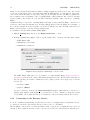
2. An Update Net Decomposition dialog box will appear (see Figure 1.24). Click on the Create button.
This will show an Update Net Variable dialog box (see Figure 1.25).
3. Enter the Name of your variable, choose the Type and intended Usage of the variable from those listed,
then click Done, then Done again to close the Net Decomposition dialog.
Enter “StudentNumber” for the name of the variable, leave the type as “string”, and set the Usage type
1.5. ADDITIONAL SPECIFICATION FEATURES
31
Figure 1.23: A “Geek” net variable with a valid initial value
Figure 1.24: Updating “Attend University” Net Variables
to “Local”. Leave the initial value blank. Click Done (see Figure 1.25). Create another Net Variable
with the name “SubjectCode” and Type “string”. Leave the Initial Value blank and set the Usage to
“Local” (usage types will be explained a little later). Click Done.
32
CHAPTER 1. THE EDITOR
Figure 1.25: The Net Variable “Student Number”
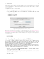
4. The Net Variables should now appear in the Update Net Decomposition of Net “Attend University”
dialog box (Figure 1.26).
Figure 1.26: Updated “Attend University” Net Variables
1.5. ADDITIONAL SPECIFICATION FEATURES
1.5.4
33
Task Decomposition
By choosing the Select Task Decomposition. . . option when you right click on a task, you have the ability
to identify which decomposition is attached to the task. A decomposition describes the variables ‘handled’
by the task, and the YAWL Service that will be responsible for performing the work the task represents at
runtime.
Like nets, tasks have decompositions where you can specify variables and a label to associate with the task.
Unlike nets, which cannot share net decompositions, there is a 1:N relationship between task decompositions
(scoped to the entire specification) and their tasks (scoped to nets), meaning that a number of tasks within
a specification may share the same decomposition.
Besides variables and a label, task decompositions also allow the workflow designer to identify which web
service the decomposition should invoke in a running workflow engine, and whether the decomposition will
create manual (i.e. human-actioned) or automated (non-human-actioned) tasks. When two tasks share the
same decomposition, we are saying that the same activity is required in two different places in the workflow
(the two tasks may be named the same or differently, but they will share the same underlying definition of
work).
From the Select Task Decomposition dialog, you can use the drop-down list to select an existing decomposition, or alternately you can click the Create. . . button to generate a new one that will become the task’s
decomposition (Figure 1.27).
Figure 1.27: Select Task Decomposition (example ‘Get a Job’ task)
1.5.5
Task Decomposition Detail / Task Variables
You can add variables to a task to store specific information relating to that task, in a similar way to adding
variables to a net. Task variables have several uses. One use is for transferring information between workflow
users and the workflow engine. A second use is for passing data between web services and/or external code
and/or applications that the running workflow engine invokes and the Net the task resides in.
For example, if your task is called ‘Purchase a Book’, you may want to store the name and/or ISBN of the
book being ordered.
1.5.6
Adding a Variable to a Task
1. First select the task that will require the variable.
We will be setting up variables for the “Enrol” task. Go to the “Attend University” Net and select the
“Enrol” task.
34
CHAPTER 1. THE EDITOR
2. Right-click on the task and choose Task Decomposition Detail. . . . An Update Task Decomposition
dialog box will appear.
Retrieve the decomposition detail for the “Enrol” task.
3. Click on the Create. . . button. An Update Task Variable dialog box will appear.
Figure 1.28: Updating the Task Variable
4. Enter the Name of your variable, choose the Type of the variable and its Usage from those listed, click
Done, then Done again to exit the task decomposition detail dialog.
Enter “StudentNumber” for the name of the variable, leave the type as string, and set the Usage to
“Input & Output”. (Figure 1.28). Click Done. Create another variable for the same task, called
“SubjectCode” with type string and usage of “Input & Output”. Click Done.
5. The “Enrol” task now has two variables, “StudentNumber” and “SubjectCode” (Figure 1.29).
1.5.7
Task Parameters
A parameter defines how a value is assigned to a variable, and how a value is passed between net-level
and task-level variables and vice-versa. Both Input and Output Parameters can be assigned to any tasks
(depending on their usage type) to allow the passing of state between nets and their tasks, and between
tasks and workflow engine, users and web services. Data may also be assigned to and from net and/or task
variables directly from an external data source (more later in this section).
Defining Parameters with XQuery
Parameters may be defined using XQuery expressions2 . Input Parameters use an XQuery expression to
specify a value (possibly drawing on a number of static and/or net-level variable values) that can be passed
2 An examination of the XQuery language is beyond the scope of this chapter; good XQuery learning resources can be found
at www.w3schools.com/xquery/default.asp and www.xquery.com/developers/
1.5. ADDITIONAL SPECIFICATION FEATURES
35
Figure 1.29: The Update Task Decomposition dialog for the Enrol task
to a single selected task variable. Output parameters use an XQuery expression to specify a value that can
be passed to a single selected net variable.
For example, if a task is called ‘Lookup Book’, then an Input Parameter could pass the name of the book to
a task variable, whereas the Output Parameter of that task may produce the corresponding ISBN for that
book.
To add an Input Parameter:
1. Select the task to add the parameter to.
We will be setting up Input Parameters for the variables that we created in the Adding / Updating
Task Variables section previously. Go to the “Attend University” Net and select the “Enrol” task.
2. Right-click on the task and choose Update Parameters Mappings. . . . An Update Parameter dialog
box will appear (Figure 1.30).
Update the Parameters for the “Enrol” task. Notice that the dialog in Figure 1.30 lists both this task’s
36
CHAPTER 1. THE EDITOR
Figure 1.30: Updating Parameters for a Task
variables, and the variables of its containing net.
3. In the Input Parameters section, click on Create. . . . An Update Task Parameter dialog box will
appear. If you have already set up a Task Variable for this task, then the Existing Task Variable option
will be activated and there will be a list of task variables to choose from. Choose a variable from the
list and click on Done, then Done again to close the task parameters dialog.
If you haven’t set up Task Variables, then click on Create. . . and return to the previous section
dealing with Task Variables (Section 1.5.7).
If you are familiar with XQuery syntax, then you can add an XQuery expression to allow manipulation
of the Input Parameters. “Syntactically well formed” XQueries will be green, and badly formed ones
will be red. Again, red text will be accompanied by a split-pane table, returning the parse errors that
cause the text to be badly formed.
For workflow designer convenience, two XQuery buttons are supplied to automatically generate XQuery
expressions from available net variables.
The add XQuery of element’s content button will return just the content of the XML element for
this variable, which is useful for simple value transfer between two variables of the same XML Schema
type, and is expected will be the button used in most cases.
The other button, add XQuery of entire element, will return the entire XML element of the
selected variable, which is useful for times when you want to create a complex type expression from
individual variable elements. Experience with XMLSchema and XQuery are necessary to understand
the effects this button will have on runtime YAWL engine state.
Select the “StudentNumber” variable from the list of Existing Task Variables. Select the “Student-
1.5. ADDITIONAL SPECIFICATION FEATURES
37
Number” net variable, then click add XQuery of element’s content (Figure 1.31). Click Done.
Create another Task Parameter and map the net “SubjectCode” to the task variable of the same name
using this technique. Click Done and Done again.
Figure 1.31: Passing a net’s StudentNumber value to a Task variable
To add an Output Parameter:
1. First select the task to add the parameter to.
We will be setting up Output Parameters for the variables that we created in the Adding / Updating
Task Variables section. Go to the “Attend University” Net and select the “Enrol” task.
2. Right-click on the task and choose Update Parameters. . . . An Update Parameters dialog box will
appear (Figure 1.31).
Update the Parameters for the “Enrol” task.
3. In the Output Parameters section, click on Create. . . . An Update Net Parameter dialog box will
appear (similar to Figure 1.31).
4. If you have already set up a Task Variable for this task, then the Existing Task Variable option will
be activated and there will be a list of task variables to choose from. Choose a variable from the list
and click on Done, then Done again to close the task parameters dialog. If you haven’t set up Net
Variables, then click on Create. . . and return to the previous section (Section 1.5.3).
38
CHAPTER 1. THE EDITOR
If you are familiar with XQuery syntax, then you can paste in an XQuery to allow manipulation
of the Output Parameters. “Syntactically well formed” XQueries will be green, and badly formed ones
will be red. For workflow designer convenience, two XQuery buttons are supplied to generate XQuery
expressions from available task variables.
The add XQuery of element’s content button will return just the content of the XML element
for this variable, which is useful for simple state transfer between two variables of the same XML
Schema type, and expected to be the typical button that users will start out with.
The other button, add XQuery of entire element, will return the entire XML element of the
selected variable, which is useful for times when you want to create a complex type expression from
individual variable elements. Experience with XMSchema and XQuery are necessary to understand the
effects this button will have on runtime YAWL engine state.
From the list of task variables, select the “SubjectCode” task variable and click add XQuery of
element’s content. From the list of net variables, select the “SubjectCode” variable. Click Done.
Create another Task Parameter and map the task “StudentNumber” to the net variable of the same
name using this technique. Click Done and Done again.
These Parameters were set up to demonstrate a simple transfer of state from a net to a task and back
to the net. Perhaps the task would allow a user to change the values of one of the variables which
would eventuate in the net’s values changing.
The Update Parameters dialog box should appear as in Figure 1.32.
Now that we have an understanding of net-level and task-level tasks, and how to create parameters to map
values between them, we can revisit the earlier example from Section 1.5.7, where we created two local
variables for the sub-net “Attend University”. By creating them with local usage type, they have local
scope and so are actually different variables than those of the same name created in the outer (parent) net
“My Career”. If you wanted to map the values of those variables from the parent net to the sub-net, then
their usage type in the sub-net will need to be changed from local to Input Only (since they are not to
be updated in the sub-net’s tasks), the perform the appropriate mapping between the parent net and the
“Attend University” composite task, following the method described above.
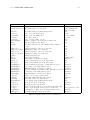
Defining Parameters using External Data Sources
As an alternative to mapping parameter values from net-level to task-level and back again, task (and case)
parameters may be assigned values directly from an external data source on starting and be directly mapped
back on completion. External data sources are accessed via a specific Data Gateway. To see a list of available
data gateways, choose the ‘Data Gateway’ tab in the Update Task Parameter dialog (Figure 1.33).
Figure 1.33 shows a single data gateway in the list (SimpleExternalDBGateway, an example gateway that
ships with YAWL) – any other gateways defined for particular specifications will also be listed here (see
Note below). The combo box at the bottom of the dialog shows which parameter will receive the data from
the gateway selected. When the Done button is clicked, the selected gateway will be displayed as a special
external mapping expression in the Update Parameters dialog (Figure 1.34).
A case-level external data gateway may also be chosen, so that each time a case is started for a specification
the chosen data gateway will be called to populate its case-level variables, and when each case completes,
the data gateway will be called to update output values from the case back to the specified external data
source. To choose an external data gateway at the case level, select Net – Set Starting Net. . . from the
main menu, then choose the desired external data gateway from those listed in the dropdown on the dialog
that displays (Figure 1.35).
Note: Specific data gateways must be created for each specification that wishes to access an external data
1.5. ADDITIONAL SPECIFICATION FEATURES
39
Figure 1.32: Established task parameters with XQuery mappings
source directly. How to create a data gateway is outside the scope of this manual. Please refer to the YAWL
Technical Manual for details.
Notes about parameters:
•
For simple assignments, such as those in Figure 1.32, the XQuery expressions for the input parameters
follow the form {/name of net/name of variable/text()} and are mapped to a task variable, while those
for output parameters follow the form {/name of task/name of variable/text()} and are mapped to a
net variable.
•
An Input Usage mode means that the variable requires a value to be mapped into it when its task
starts (via an input parameter). An Output Usage mode means that the variable is required to map a
value from it (typically to a net-level variable) when its task completes (via an output parameter). An
Input & Output Usage mode combines both requirements.
•
Only Net-level variables may have a Usage mode of Local, which signifies a scope within the net but
not external to it. Thus, sub-nets require net-level variables with modes other than Local to support
data passing to and from their parent nets. A root (or top-level) net with variables of type Input Only
or Input & Output will, when started, request values for those variables from a user via a form, before
the first task in the net is activated. No action is taken for Output modes set for root net variables.
•
Input parameters may only be created for variables of mode types Input Only or Input & Output.
•
Output parameters may only be created for variables of mode types Output Only or Input & Output.
•
A single task may map some parameters via XQuery and other parameters via external data gateways
(as in Figure 1.34).
40
CHAPTER 1. THE EDITOR
Figure 1.33: The Data Gateway tab
1.5.8
Flow Detail
When dealing with tasks that have XOR and OR splits, we need some way of defining which flows should
be activated at runtime. This is achieved by associating a boolean XQuery expression with each flow. At
runtime, the flow expressions are evaluated and:
•
if the split type is an OR-split, each flow that has an expression that evaluates to true will be executed.
•
if the split type is an XOR-split, the first listed flow that has an expression that evaluates to true will
be executed.
Since it is possible that all flow expressions evaluate to false, XOR and OR splits must nominate a default
flow, which will activate if all of the other flow expressions evaluate to false, to ensure that the workflow does
not deadlock (i.e. is not blocked at that point from proceeding and eventually completing). Default flows are
defined by prioritising the order in which the various flows of a split are evaluated – the one prioritised last
in the order becomes the default flow.
To update the flow detail of a task that has a split, right click on the task and choose Update Flow
Detail. . . . The “Flow Detail” dialog appears, which list the flows coming out of the split and each flow’s
corresponding Predicate (or flow expression).
The arrowed buttons to the right of the list allow you to reorder the evaluation sequence of the predicates, so
that the default predicate (the one you want to activate when all others fail) can be placed at the bottom of
the list. Carefully ordering the evaluation sequence is especially important when dealing with an XOR-split,
because only the first that evaluates to true will be activated, and all subsequent flows will be ignored.
1.5. ADDITIONAL SPECIFICATION FEATURES
41
Figure 1.34: Established task parameters with external mappings
Figure 1.35: Setting an external data gateway from case start and completion
The currently selected flow in the dialog will be identified by being highlighted green in the Net (Figure 1.36).
To specify a predicate for a particular flow, select the flow from the list and click on Predicate. . . . Enter
a predicate as a boolean XQuery expression and choose Done. (Note that a net-level local integer variable
called ‘score’ has been introduced to the net for the purposes of showing how to create a boolean XQuery
expression for a flow predicate; it is not used again in this tutorial).
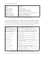
Timer Predicates
Timer predicates are special (non-XQuery) expressions that may be used as flow predicates. For each task
that has a timer associated with it (cf. Section 1.11) an implicit, net-level timer-state variable is created and
maintained at runtime. At any particular time during the execution of the net, a timer-state variable can
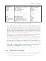
have one of four values (Table 1.1).
42
CHAPTER 1. THE EDITOR
Figure 1.36: Updating Flow Detail
dormant
active
closed
expired
Timer has not yet started
Timer is running
Task completed before timer expired
Timer expired before task completed
Table 1.1: Valid states of timer state variables
A timer predicate can have one of two operators, = (equals) or != (not equals), and takes the form:
timer(name of task ) operator ‘timer-state’
For example, assuming a task called ‘Enrol’ has a timer, then on any outgoing flow from an OR-split or
XOR-split in the net that contains the ‘Enrol’ task, the following example timer predicates are valid:
•
timer(Enrol) = ‘dormant’
•
timer(Enrol)=‘expired’
•
timer(Enrol) != ‘expired’
Note: Timer predicates are case-sensitive (including the ‘timer’ keyword, the name of the task and the state
value).
1.5.9
Multiple Instance Queries
Now that we have an understanding of parameter setting and XQueries, we can revisit, from a data perspective, parameter setting for the particular requirements of Multiple Instance (MI) Tasks. In general terms, an
MI task receives, as input from a net-level variable mapping, a variable of complex type, typically a list of
some other data type (but more complex constructions are of course supported too), which it then splits into
a number of logically distinct data values, to form the data that is assigned to each task instance. When the
MI task completes, it gathers all the individual pieces of data from the various task instances and reconstructs
the complex type variable so that it can be mapped back to the net-level variable.
To illustrate the operation of MI tasks, with particular emphasis on the data perspective, we will use the
“List Builder” specification shown in Figure 1.37, which begins by compiling an ‘order’ – a list of book titles.
1.5. ADDITIONAL SPECIFICATION FEATURES
43
Figure 1.37: Example specification with a Multiple Instance Task
It then creates a number of MI task instances, one for each book title in the list of books. Once all the MI
task instances complete, the updated list is recomposed and shown in the final task.
To prepare this specification, drag two atomic tasks and one MI task onto the canvas. We then need to define
a complex data type to store the entire book order. Open the Update Data Type Definitions dialog from the
Specification menu, and enter the following two complex type definitions:
< xs:schema xmlns:xs = " http: // www . w3 . org /2001/ XMLSchema " >
< xs:complexType name = " BookOrder " >
< xs:sequence >
< xs:element name = " title " type = " xs:string " / >
< xs:element name = " price " type = " xs:double " / >
< xs:element name = " inStock " type = " xs:boolean " / >
</ xs:sequence >
</ xs:complexType >
< xs:complexType name = " BookList " >
< xs:sequence >
< xs:element maxOccurs = " unbounded " name = " order " type = " BookOrder " / >
</ xs:sequence >
</ xs:complexType >
</ xs:schema >
The first defines a complex type called ‘BookOrder’, which is a record with three simple type fields. The
second defines a complex data type called ‘Booklist’, which consists of an array of one or more elements
called ‘order’, of BookOrder type (‘unbounded’ means there is no upper limit on the number of order records
we can include in the book list). Once this is added, we can start populating the data perspective of the
specification:
•
Create a net-level variable called MasterList of type BookList and usage Local (Tip: In the Update
Variable dialog ‘Type’ dropdown, user-defined types are listed after all the built-in simple types). Give
the variable this initial value:
< order >
< title > YAWL User Manual </ title >
< price > 0.00 </ price >
< inStock > false </ inStock >
</ order >
When entered correctly, the text will become green to show that it is a valid value to assign to the
Masterlist variable of complex type ‘BookList’, since it defines values for the elements of one BookOrder. It is important that an initial value is provided for this variable, because our definition of the
‘BookList’ type specifies that it will contain at least one element (that is, because it doesn’t include a
‘minOccurs=0’ clause). If there was no initial value specified for this type, the specification would fail
schema validation at runtime – in other words, the Engine will reject the specification.
44
CHAPTER 1. THE EDITOR
•
Add a decomposition to the first atomic task, and call it ‘Create Book List’. Add to the decomposition
a variable called bookList of type BookList and usage Input & Output. Then, open the Update
Parameter Mappings dialog, add an input parameter mapping the net-level Masterlist variable to the
task’s bookList variable, and an output parameter to map it back again (see Figure 1.38). This task
will allow a user to add any number of book orders to the master book list.
Figure 1.38: Update Parameter Mapping dialog for task ‘Create Book List’
•
Add a decomposition to the other atomic task, and call it ‘Show List’. Add a variable to the decomposition similarly to the first task, except that the usage should be Input Only, and so only an input
parameter mapping is required. This task will show the user the results of any data changes done during
the execution of the MI task, thus its variable is input only (meaning that the values are ‘display-only’).
•
Add a decomposition to the MI task and call it ‘Verify List’. To the decomposition, add a variable
called book of type BookOrder and usage Input & Output. Note carefully that the task variable
we have added to the decomposition is of BookOrder type – in our data definition we have defined the
BookList type being comprised of a number of BookOrder type elements – so what has been defined in
this decomposition is a mapping of a single BookOrder to each task instance that will be created when
the MI task is executed.
•
The mapping of input and output parameters for MI tasks is done a little differently to atomic (single
instance) tasks, and involves a two stage process. Open the Update Parameter Mapping dialog for the
MI task ‘Verify List’ and add the input and output parameter mappings as seen in Figure 1.39. Notice
that the input parameter maps the entire net-level variable ‘MasterList’ to ‘book’, a single task-level
BookOrder variable, while the output parameter maps the contents of the ‘book’ variable, wrapped
1.5. ADDITIONAL SPECIFICATION FEATURES
45
in ‘order’ tags, back to the net-level ‘MasterList’. These kinds of mappings would be invalid for a
single-instance task, but here we need to define a mapping that on input takes a net-level list, assigns
each member of the list to a task instance, and on output takes each task instance’s variable and maps
it back to the net-level list. The intermediary steps that allow this mapping to occur is done in the
second stage of the mapping process.
Figure 1.39: Update Parameter Mapping dialog for MI task ‘Verify List’
•
Right click on the ‘Verify List’ MI task and choose Set Instance Detail. . . from the popup menu. On
the Bounds tab page, set minimum instance to 1, maximum instances to 20, continuation threshold
to 5 and ‘static’ instance creation type. These settings mean that between 1 and 20 task instances will
by started from this MI task at runtime (depending on the number of book orders in the book list),
the MI task will complete when 5 instances complete (or all complete if less than 5 were started) and
new instances may not be dynamically started after task execution begins.
Now, click the Queries tab page. It is here that we will specify how the BookOrders contained in
the MasterList variable will be ‘split’ into individual task variable instances and how those instance
variables are ‘aggregated’ back into the MasterList on completion. Figure 1.40 shows the Queries tab
page for the ‘Verify List’ MI task. There are six parts to this dialog, four requiring XQueries and two
variable settings:
– Multiple Instance Variable: this specifies the task instance variable that has been defined to
accept a single item from the net-level ‘list’ variable – in our case, the ‘book’ variable.
– Accessor Query: this query defines the source of the data that needs to be split into multiple
46
CHAPTER 1. THE EDITOR
Figure 1.40: Set Instance Detail dialog, Queries tab for MI task ‘Verify List’
task instances, in most cases (as in our example) it is a simple XPath expression specifying the netlevel variable that is being mapped into the MI task, and exactly matches the input parameter set
for the variable in the Update Parameters dialog. In this case, it is /List Builder/Masterlist –
note that it is the same XQuery expression as the task’s input parameter as shown in Figure 1.39.
– Splitter Query: the splitter is an XQuery expression that is used to take the ‘list’ variable
mapped in and ‘split’ it into a number of ‘child’ elements, one for each member of the list. In
natural language, the query reads “for each element in the accessor variable, return that element”.
In our example, the XQuery is: for $e in /MasterList/* return <book>{$e/*}</book>
The $e part is a query variable – all query variables start with a $ sign followed by one or more
characters ($e is a convention for a loop variable, but other names are, of course, allowed). The
return value for each $e in our query would start and end with ‘order’ tags; since our variable
is called ‘book’, we have to replace the ‘order’ tags with ‘book’ tags, so the return value of our
XQuery is the contents of the order ({$e/*}), but surrounded by ‘book’ tags. The final result is
1.5. ADDITIONAL SPECIFICATION FEATURES
47
a number of ‘book’ values, each corresponding to one ‘order’ element in MasterList.
– Instance Query: this query defines how the ‘book’ variable within each task instance should be
formatted prior to being mapped back to the net-level MasterList. Like the splitter query above,
we need to replace the surrounding ‘book’ tags with ‘order’ tags, the contents of the element being
the contents of the ‘book’ variable ({/Verify list/book/*}). Notice also that this query exactly
matches the task’s output parameter in Figure 1.39.
– Aggregate Query: puts all the instance query results into a list (in this case, a list of ‘order’
elements) ready for mapping back to the net-level variable. The aggregate query will look exactly
like this in most cases, except that the outermost braces are optional. ($d is used simply to
differentiate it from $e in the splitter query, but its name is unimportant).
– Result Net Variable: this specifies the net-level variable to which the results of the aggregate
query is to be mapped.
Figure 1.41: Update Parameters dialog, ‘Get Quotes’ task
When this specification is executed, it will first allow the user to specify a number of book orders, then will
split the details of each into a corresponding number of MI task instances, one for each order. The price and
availability of each order can be updated within its own task instance. When all (or the threshold) of MI
task instances have completed, their data will be aggregated back into the list for display in the third and
final task.
For a second example, consider a process that raises a purchase order to purchase a particular product. The
business rules for this process require that at least three quotes are needed for any purchase, from which one
is chosen to fill the order. A multiple instance task called Get Quotes is used to gather the product quotes
from suppliers. The Update Parameters dialog for the Get Quotes task can be seen in Figure 1.41.
48
CHAPTER 1. THE EDITOR
Figure 1.42: Instance Detail dialog for the ‘Get Quotes’ MI task
The task has two variables defined: ‘PONumber’ (the purchase order number) and ‘Supplier’ (the details
of a single supplier). Notice that ‘PONumber’ is defined as Input Only, and is mapped from the net-level
variable of the same name – this means that the purchase order number will be displayed within each of the
workitems created from the MI task. Notice also that while a list of Suppliers is mapped in from a net-level
variable, the mapping expression maps to a single supplier – one for each task to be created. Also, the Output
Parameter mapping takes a single Supplier from the task and maps it to the net-level list of Suppliers.
The MI queries for the task can be seen in Figure 1.42. Again, note that the Accessor Query exactly matches
the Input Parameter Expression, and the Instance Query exactly matches the Output Parameter Expression,
as can be seen in Figure 1.41. The Splitter Query in this example is a little simpler than the earlier one,
since we don’t have to worry about different tag names for the split data because out task-level variable has
the same name as its data type, so it takes the less complicated form for $s in /Suppliers/* return $s
(for each Supplier in the list of Suppliers return that Supplier). The Aggregate Query takes the same form
as the previous example.
When the instance creation type is set to dynamic, then new instances of the MI task may be created at
runtime after the task execution has begun and split into its instances. There is a button on the default
1.6. CONNECTIONS
49
worklist handler to accommodate this (see Chapter ??), which will be enabled for dynamic MI tasks until
such time as the maximum instances bound has been met.
1.5.10
Fast-Tracking Data Definition
If all of a task’s input and output parameters will involve a simple mapping to and from net-level variables,
a “fast-track” can be taken to do it all in a few mouse clicks. To achieve this, right-click on an atomic task
that does not yet have a decomposition, and select Decompose to Direct Data Transfer. The dialog in
Figure 1.43 will appear.
Figure 1.43: An example of the direct data transfer dialog
All of the available net-level variables for the task’s containing net will be listed in the dialog. Simply check
the boxes for the desired inputs and outputs. This dialog will automatically create a task decomposition and
matching XQueries to directly transfer data from a selected net variable to a task variable of the same name
and back again.
1.5.11
End of Scenario
This is where our scenario ends. The My Career Scenario was designed to outline the basic the functions of
the YAWL Editor and to provide you with a understanding of designing a YAWL workflow specification.
But the functionality of the YAWL Editor does not stop here. If you are after something more challenging,
try adjusting your version of the scenario to expand into more sub-Nets and more complex situations.
1.6
1.6.1
Connections
Connecting to the YAWL Engine
Each atomic task in a YAWL specification must be associated with a ‘service’ that will be responsible for
performing the work of the task. If you do not explicitly specify a service for a task, by default the task will be
50
CHAPTER 1. THE EDITOR
assigned to the Default Worklist Handler, which by default is supplied by the Resource Service. If you want
to associate a task with a service other than the Default Worklist Handler, you can make the appropriate
choice from a list in the task’s decomposition dialog (see the following section). The Editor populates the
list of available services by making a call to a running Engine, which returns the list of services currently
registered with it. Before this can occur, the Editor must first establish a valid connection to a running
Engine.
On Editor startup, a connection to a running Engine is attempted. If successful, the Engine connection icon
at the left of the status bar will turn green. If unsuccessful (perhaps because the Engine is not running, or
the connection parameters are incorrect) the connection icon will show red. After the Editor has started, an
Engine connection may be performed via the Settings menu.
To establish a connection with a running YAWL Engine:
1. Click the Settings Menu and choose the Engine Connection . . . item.
2. From the resulting dialog (Figure 1.44), accept the default values or enter the following engine details:
•
YAWL Engine URI;
•
Administrator’s User Name;
•
Administrator’s Password.
Figure 1.44: Specifying the YAWL Engine connection detail
The YAWL Engine URI value is set by default to a locally installed Engine (http://localhost:
8080/yawl/ia), but should be changed if the Engine is installed remotely. The User Name and Password
have the following case-sensitive defaults (but can be changed via the Client Applications web-form
(Section ??):
•
user name: editor
•
password: yEditor
As a user convenience, a button called Test Connection is supplied, which will test a connection to a
running engine with the detail supplied for correctness before you are committed to using those details
for any further editor/engine interactions. To finalise the connection settings, click the Done button.
1.6.2
Connecting to the Resource Service
To use the organisational data managed by the Resource Service for assigning tasks to Participants or Roles,
a connection between the editor and the Resource Service needs to be established.
Like the Engine connection (above), when the Editor starts a connection to a running Resource Service is
attempted. If successful, the Resource Service connection icon at the left of the status bar will turn green.
1.6. CONNECTIONS
51
If unsuccessful (perhaps because the Service is not running, or the connection parameters are incorrect) the
connection icon will show red. After the Editor has started, a Resource Service connection may be performed
via the Settings menu.
To set the Resource Service connection details:
1. Click on the Settings menu and choose the Resource Service Connection. . . item.
2. From the resulting dialog (Figure 1.45), accept the default values or enter the following engine details:
•
YAWL Engine URI;
•
Administrator’s User Name;
•
Administrator’s Password.
Figure 1.45: Specifying the Resource Service connection
The Resource Engine value is set by default to a locally installed Resource Service (http://localhost:
8080/resourceService/gateway), but should be changed if the Engine is installed remotely. The User
Name and Password have the following case-sensitive defaults (but can be changed via the Client Applications
web-form (Section ??):
•
user name: editor
•
password: yEditor
1.6.3
Connecting a Decomposition to a registered YAWL Service
You can use task decompositions within your workflow to make a connection to custom YAWL services that
have been registered with a running engine. By associating a task decomposition with a custom service, all
task instances based on that decomposition will be passed to the custom service at runtime for processing –
that is, the custom service is responsible for performing the work of the task instance.
For example, a decomposition may be set up to place an order with an external company. Upon execution of
any task using this decomposition, data could be transmitted via a Web Service invocation to this company.
To have a decomposition invoke custom YAWL service, do the following:
1. Right-click on a task, the choose Task Decomposition Detail. . . . An Update Task Decomposition
dialog box will appear (see Figure 1.29).
2. In the “YAWL Registered Service Detail” panel, Select the required Web Service from the dropdown
list of those available in the Engine.
3. Click Done to finish.
52
CHAPTER 1. THE EDITOR
If the Editor is connected to a valid running YAWL Engine instance, the YAWL Service Dropdown Box will
contain entries for all custom YAWL services the engine has registered. Otherwise, only the Default Worklist
(of the Resource Service) will be available.
When you select a YAWL Service, the Editor will query this running engine for the mandatory input and
output variables required by the service (if any), and will populate the decomposition variables of the selected
task with those variables. Core custom services that are supplied with the engine include one for RPC-Style
Web Service Invocation (WSInvoker Service), and one for supporting flexibility and exception handling for
YAWL processes (Worklet Service). Optional services include an SMS handler, a digital signature service
and a email sender service.
1.7
Validating and Saving a Specification
At any stage you can validate and/or save your specification to a YAWL Engine file (.yawl).
To validate your specification:
, on the Menu Toolbar or click Specification on the Menu and choose
1. Click the Validate button,
Validate Specification. . . .
2. If problems are detected, a table listing them will appear at the bottom of the Editor with details of
any inconsistencies that would stop the specification from running in the YAWL Engine. Figure 1.46
show a specification with no validation problems. Figure 1.47 shows an example invalid specification,
where the Validation Problems table shows that the ‘Bad Task’ task has no outgoing flow, and is not
on a path between the input and output conditions.
Figure 1.46: A valid specification
To save your specification to file:
1.7. VALIDATING AND SAVING A SPECIFICATION
53
Figure 1.47: A invalid specification
1. Click on the Save button,
, on the Menu Toolbar or click Specification on the Menu and choose
Save Specification. . . . The ‘Specification File Save Options’ dialog appears (Figure 1.48).
Figure 1.48: Specification File Save Options dialog
If this is the first time the specification has been saved, and a ‘Specification ID’ has not yet been entered
via the ‘Update Specification Settings’ dialog, a ‘Specification ID’ field will appear in the dialog (all
Specifications must be given a valid ID). The ID can be a combination of alphanumeric characters and
the underscore, but cannot start with a numeric character. Once set, this field will not reappear in
54
CHAPTER 1. THE EDITOR
subsequent saves of the specification.
The ‘Version Number’ field provides a version number for the specification. Version numbering allows different versions of the ‘same’ specification to co-exist in the Engine. YAWL specification version
numbers consist of a major part (to the left of the point) representing a major revision, and a minor part
(to the right of the point) representing a minor revision. Version numbers begin at 0.1; you may edit the
version number directly to a higher version number at any time. If the ‘Auto Increment Minor Version
Number’ checkbox is checked, the minor revision will increase by one each time the specification is saved.
The ‘Verify on save’ and ‘Analyse on save’ checkboxes, if checked, will verify and and/or analyse
the specification before it is saved, providing a final check of the specification (note: verification and
analysis may take some time for large and/or complex models, and analysis in particular should be
unchecked for incremental saves of such models).
The ‘Create backup’ checkbox, if checked, will copy the previous version of the specification file to
a file of the same name, but with a .bak extension. Checking this option is recommended.
Once the dialog is completed, click OK to save the file.
This saved specification file can now be loaded into a running YAWL Engine and executed.
To import a specification file from a pre-2.0 version of the editor (i.e. a .ywl file):
, on the Menu Toolbar or click Specification
1. Click on the “Import a YWL Specification file” button,
on the Menu and choose Import from YWL File. . . .
A window will appear asking you specify the YWL file to import.
2. Select the file and choose Open.
The YWL file will be loaded and converted to a YAWL 2.0 version specification. The specification
can now be edited and saved as a 2.0 specification in the usual way.
1.8
Specification Analysis
Verification of specifications for the engine only determines whether the engine will be able to successfully
load and begin execution of the specification. In contrast, the analysis tool can be used to test for deeper
issues in the specification.
The analysis toolbar button,
, or the matching Analyse Specification menu item under the Specification
menu allows workflow designers to analyse their specifications. A number of potential problems with a workflow can be automatically spotted with analysis. Examples include spotting potential deadlock situations,
unnecessary cancellation set members, and unnecessary or-join decorators (at run-time, or-joins require significant processing effort, and should be removed or replaced with other join types if they are not actually
needed).
A configuration dialog for specification analysis is available via the Tools menu, Configure Specification
Analysis (see Figure 1.49). Note that many of the options are disabled by default since they are resource
intensive and may take some time to complete for large and/or complex workflows. It is recommended
that analysis of such specifications not be done incrementally, but rather at planned checkpoints during
specification development.
Because analysis make take a long time and is very resource intensive, it may appear that the Editor has
frozen during an analysis (although it is very unlikely that this will actually be the case). To provide some
feedback about the progress of the analysis, a dialog will appear which shows updates and messages (see
1.8. SPECIFICATION ANALYSIS
55
Figure 1.50). The dialog includes a checkbox that, when checked, will keep the dialog open after the analysis
completes so that the messages may be noted. This functionality can also be controlled via a setting in the
Configure Specification Analysis dialog (see Figure 1.49).
Figure 1.49: Configure Specification Analysis dialog
Figure 1.50: Configure Specification Analysis dialog
If the optional YAWL specification analysis utility wofyawl.exe, is supplied in the same directory as the
Editor, an extra tab entitled WofYAWL Analysis will be enabled in this dialog, allowing more analysis
56
CHAPTER 1. THE EDITOR
options than those supplied by default. The utility must be compiled for specific architectures3 . The current
version of the Editor needs version 0.4 of the utility.
1.8.1
Verification and Analysis Explained
This section provides a brief overview of verification in YAWL. Verification is concerned with the design time
detection of certain undesirable characteristics in process models.
Extensive research has been conducted in the area of workflow verification. One of the pioneers of this work
is Wil van der Aalst. He formally defined the notion of soundness as a correctness notion for workflow nets.
This class of Petri nets forms a predecessor of YAWL, which does not support OR-splits/joins, Multiple
Instance Tasks and cancellation regions. Informally speaking a workflow is sound iff [1]:
•
The net has the option to complete. That means that from every reachable state the final state, where
there is a single token in the output condition, can be reached.
•
The net has proper completion. This means that when the output condition is marked there are no
other tokens anywhere else in the net.
•
The net has no dead tasks. These are tasks that cannot be executed in any scenario.
For YAWL, the notion of weak soundness was introduced as it can be theoretically proven that soundness
is not decidable [6]. For a finite state space, we can simply try and check all reachable states, but this is
obviously not possible when this state space is very large or infinite. In those cases, we can check whether
it is possible to reach the final state from the initial state. Hence, does a scenario exist where we reach the
final state?
The richer concepts offered by YAWL also introduce additional correctness notions. For example, an analyst
may have used an OR-join where an XOR-join or an AND-join could have been used. This is not desirable
for computational reasons, but also because it makes the process model harder to understand. Hence, the
YAWL environment will check whether all OR-joins are immutable. Another correctness notion is that of
irreducible cancellation regions. Here it is checked whether certain conditions or tasks can be removed from a
cancellation region as they will never contain a token or will never be active when the associated cancellation
task executes.
The YAWL editor offers two different approaches to automated verification. One approach [6] is based on
the theory of Reset nets (this is built into the Editor). The other approach [5] uses Petri net theory and
in particular, the concept of transition invariants. For this latter approach the program wofYAWL is to be
used (the executable of this program should be put in the same directory as the Editor under the name
wofyawl0.4.exe). These approaches are different in that there are workflow specifications where one of them
can pick up an error which the other approach cannot.
By choosing “Configure Specification Analysis” under the Tools menu in the Editor one can choose what
type of verification the YAWL editor needs to perform. As some forms of verification may require quite a bit
of time it is important to choose the right approach and generally speaking, it is probably best not to verify
every intermediate version of a specification.
The screen shot shown in Figure 1.50 shows the options one can choose for the analysis based on Reset nets.
This form of analysis supports the use of reduction rules. YAWL reduction rules can be applied to the net
and Reset net reduction rules can be applied to the Reset net that results from the mapping of a YAWL net.
The application of these reduction strategies may significantly reduce the workflow that needs to be analysed,
hence it may significantly reduce the time that verification takes. Note that there is overhead associated with
performing the reductions themselves. Also worth mentioning is that the soundness check is supported for
workflows with a finite state space. The editor caps the state space at a certain number of states and tries
to construct the reachability graph for the workflow. If the upper bound is not exceeded the soundness of
the workflow can be determined with certainty.
3 WofYAWL
is currently only available for Windows environments.
1.9. AUTOMATED TASK
57
The wofYAWL analysis tab-page of the ‘Configure Specification analysis’ dialog is shown in Figure 1.51. The
reader is referred to [5] for a detailed explanation of the concepts behind this approach to verification.
Figure 1.51: Verification using wofYAWL
1.9
Automated task
Any atomic task in YAWL that is associated with the Resource Service (i.e. the default association if the task
is not explicitly associated with another service) can have its decomposition defined as manual or automated.
A task with a manual decomposition is a task that is intended to be executed by a human resource, e.g.
a participant in the Resource Service’s organisational model. A task with an automated decomposition is
a task that is not offered to any resource but is executed by the system. This type of task can be used
to manipulate the content of net variables, from simple data assignments to complex reports generation.
Alternately it may be associated with a codelet – a discrete piece of code that is executed, optionally using
the input variables of the task, and assigning any results to the chosen output variables of the task.
Both task types are handled by the Resource Service, but the behaviour of an automated task differs as
follows:
•
on enablement, it is automatically checked out of the engine (thus having priority over manual tasks in
a deferred choice) and its input parameters are parsed;
•
if a codelet has been specified, it will be executed it using the task’s variables as required; then
•
it is automatically checked in and its output variables are mapped back to the corresponding net
variables.
A task is designated as manual by default, but can be set as automated by right-clicking on it and selecting the
Task Decomposition Detail dialog, then ticking the Automated checkbox in the External Interaction
section (see Figure 1.29). When the Automated checkbox is checked, the option Manage Resourcing in
the task’s right click menu will be disabled (since human resources are not required for automated tasks).
Data manipulation can be achieved by using the task’s variables and their Input and Output Parameters.
Parameters are generally used to copy the content of a net variable to a task variable and back again. But
58
CHAPTER 1. THE EDITOR
parameters may also contain an XQuery expression that uses static values, or the values of other variables,
to copy data between net variables and task variables. Figure 1.52 shows an simple example of copying
from expression, where the literal true is copied onto the net variable PO timedout after choosing the from
expression radio button. This choice is only available for automated tasks, and any task variables used in
the XQuery expression itself must be declared as Input & Output usage types.
Figure 1.52: An output parameter set to copy from expression for an automated task
1.9.1
Codelets
Essentially, a codelet is a discrete Java class, managed by the Resource Service, that may be enacted by
an automated task at runtime. When an automated task is enabled during process execution, and it has a
codelet associated with it, the input parameters of the task are passed to the codelet, it is executed, and any
results are passed back to the task via its output parameters.
There are currently three codelets available in the Editor (see the YAWL Technical Manual for directions on
how to add user-defined codelets):
•
ExampleCodelet: designed to demonstrate the usage of codelets;
•
XQueryEvaluator: accepts an XQuery as an input parameter, evaluates it (using other input parameters
as required by the XQuery), and produces the result to an output parameter.
•
ShellExecution: accepts an input parameter containing a command line of an external program, and
runs it, waiting for it to complete and returning the result (if any) via an output parameter.
To associate a codelet with a task decomposition, first mark the decomposition as automated by ticking the
Automated checkbox in the Task Decomposition dialog (see Figure 1.29). When checked, the Set Codelet
button is enabled; clicking that button opens the Set Codelet for Automated Decomposition dialog, listing
the available codelets (Figure 1.53). Note that a valid connection to the Resource Service is required for this
list to be populated with codelets. The dialog lists the available codelets, together with a description of what
each one does and the task variables required to successfully execute it. For example, if ExampleCodelet
is chosen, the automated task requires 3 variables to be created: input parameters ‘a’ and ‘b’, and output
1.10. RESOURCE MANAGEMENT (MANUAL TASK)
59
Figure 1.53: The Set Codelet dialog
variable ‘c’ (all of type ‘long’). These parameters must be added to the task in the normal manner – at
runtime, if the required variables are not present, the codelet will be unable to successfully complete (the
task will still complete successfully, however).
The codelet repository has been designed as ‘pluggable’, so that designers and developers can easily add
new codelets to perform various operations, which will immediately be available to process designers via the
dialog above, as long as there is a valid connection to the Resource Service.
1.10
Resource Management (Manual task)
Once a connection with the Resource Service has been established, any manual atomic task with a decomposition (a task is manual by default, and only becomes automated when explicitly checked as automated in
the Task Decomposition Dialog) can be allocated resources via a number of steps, by right-clicking on the
task and selecting Manage Resourcing. This will launch the resource manager wizard. Figure 1.54 shows
the dialog window for Step 1 of the wizard.
Step 1
In Step 1 we can specify the interaction strategy for work items of the selected task. There are three
interaction points: offer, allocation, and start, each of which may be either User or System processed.
If we choose that work items are to be Offered by the User and not by the System, at runtime an Administrator
will need to manually choose the resource(s) to offer the work item to. If System offering is chosen, then
in Steps 2 and 3, we can specify the resources that will automatically be offered work items of the task at
runtime.
If we choose that work items are to be Allocated by the User and not by the System, any participant who has
been offered the work item can manually choose whether to commit to being responsible for the performance
of the work item (i.e. to allocate the work item to themselves). If System allocation is chosen, in Step 4 we
can specify how work items will be allocated to a participant by the System.
60
CHAPTER 1. THE EDITOR
Figure 1.54: Step 1 of the resource management wizard
If we choose that work items are to be Started by the User and not by the System, then the user will choose
to manually start working on the work item at a time of their choosing. If System starting is chosen, the
work item, once it is allocated to the participant, will be immediately started.
Step 2
In Step 2, shown in Figure 1.55, we can select an initial set of resources (called the distribution set) that will
be offered work items of the selected task at runtime by the System. The distribution set may consist of any
number of participants and/or roles4 . These can be picked from the relevant lists in this dialog (multiple
selections are supported).
Additionally, in the Net Parameters panel you may nominate one or more net-level variables that at runtime
will contain a value of the userid of a participant or the name of a role (that is, deferred allocation). For a
variable to appear in the Net Parameters panel, it must be of type ‘string’ and usage ‘Input & Output’ or
‘Input Only’. Note that all net-level variables that are of string type and have one of those usage types will
be listed in the Net Parameters table, and will initially all be set as referring to ‘Data’. For each of those that
will contain resourcing information at runtime, the Refers To value must be changed to either ‘Participant’
or ‘Role’ via the drop down list on each row, depending on the type of resource the value will refer to at
runtime.
Step 3
In Step 3, shown in Figure 1.56, we can filter the set of participants that have been described in Step 2.
Filtering can be done over capabilities and/or over positions and organisational groups. Moreover, from this
dialog it is possible to:
•
4A
allow the work items of the selected task to be offered only to participants who are members of the
set specified in Step 2 and have previously completed work items of another task (as specified) in the
current process instance;
role is essentially a set of participants.
1.10. RESOURCE MANAGEMENT (MANUAL TASK)
61
Figure 1.55: Step 2 of the resource management wizard
Figure 1.56: Step 3 of the resource management wizard
•
do not allow the work items of the selected task to be offered to participants who are members of the
set specified in Step 2 and have previously completed work items of another task (as specified) in the
current process instance;
•
Allow all of the work items of the selected task to be piled to a particular participant, which means
that, if a participant chooses to pile a work item of the task, that participant will be automatically
allocated the work item and all future instances of work items of the task for all future instances of the
process containing the task, until such time as piling is turned off for that task by the participant or an
administrator.
62
CHAPTER 1. THE EDITOR
Step 4
In Step 4, shown in Figure 1.57, we can select the allocation mechanism that determines at runtime which
participant, chosen from the members of the distribution set defined earlier, will actually be allocated the
work item. The currently available mechanisms are:
•
Round Robin (by time): chooses the participant in the set who has not been allocated a task instance
for the longest time;
•
Round Robin (by least frequency): chooses the participant in the set who has been allocated this task
instance the least number of times in the past;
•
Round Robin (by experience): chooses the participant in the set who has been allocated this task
instance the most number of times in the past;
•
Random Choice: randomly chooses a participant from the set (the default); and
•
Shortest Queue: chooses the participant in the set who has the least number of task instance currently
in their work queue.
Figure 1.57: Step 4 of the resource management wizard
Step 5
In Step 5, shown in Figure 1.58, we can specify participant-task privileges (privileges that apply only for this
task). For example, we can specify whether participants are allowed to suspend the execution of work items
of the selected task.
More details on resource allocation and authorisation can be found in Chapter ??.
1.11
Task Timer
Any atomic task can be assigned a timer behaviour by right-clicking on it and selecting the Set Task
Timer. . . . The dialog in Figure 1.59 will appear.
1.11. TASK TIMER
63
Figure 1.58: Step 5 of the resource management wizard
Figure 1.59: The timer dialog for an atomic task
From this dialog it is possible to set an activation type and an expiration value for the timer. The timer can
be activated either when a task is enabled (i.e. is offered or allocated) or when it starts. These have different
meanings according to the type of task – manual vs. automated.
1.11.1
•
Activation on enablement
In the case of a manual task, as soon as the task is enabled, the timer begins and it remains live so
long as the specified expiry time is not reached. During this time frame, the task will follow the normal
64
CHAPTER 1. THE EDITOR
resource assignment policy. In other words, it will be offered and can be allocated and started. Once the
timer expires, the task instance will complete no matter what its current status is (offered, allocated,
started). The possible danger of this behaviour is that a work item might be timed out while being
edited by a user, in which case any modifications the user makes after that time are lost.
•
In the case of an automated task, the timer works as a delay, i.e. the automatic execution of the task
instance created by an automated task is delayed until the specified expiry time is reached. Once the
timer expires, the task is immediately executed and completed.
1.11.2
Activation on starting
•
In case of a manual task, the timer begins only when the task has started. Therefore, the task will be
first offered, then allocated, and once it is started the timer starts. Again, the timer may expire while
the task is being edited by a user.
•
This option is does not apply for an automated task.
1.11.3
Expiry value
The expiry value of the timer specifies for how long the timer will live after being activated. Expiry values
can be expressed in either of two ways:
•
Using a specific date and time, which means the timer will expire at the specified moment. To set
a specific date and time, choose the ‘at the time of’ radio button on the Set Timeout Detail dialog
(Figure 1.59) and enter the required values. Care should be taken when setting a specific time value for
timers – if it happens that the specified value is earlier than the moment the task is actually enabled
or started (depending on when it is set to activate), then the YAWL Engine will recognise that the
timer has already expired and immediately complete the work item before it has a chance to appear on
a worklist.
•
Using a Duration value. A Duration is one of the built-in simple XML Schema data types, and is
used to represent a period of time. When a Duration type is used as a timer expiry value, the timer
will expire exactly when that period of time has passed since the work item was enabled or started
(depending on when it is set to activate). To set a specific duration, choose the ‘after a duration of’
radio button on the Set Timeout Detail dialog (Figure 1.59) and enter the required value. A Duration
value is expressed in the following form:
PnYnMnDTnHnMnS
All values start with P (for Period) followed by a non-negative number of years, months, days, then T
(for time), followed by a non-negative number of hours, minutes and seconds. The seconds value can
have a decimal point and as many digits following the point as required (e.g. to specify fractions of
a second). Any zero value parts can be omitted. Valid examples: P1Y4M3DT23H55M1.5S, P2M3D,
PT10S. Care should be taken when specifying a duration, for example P2M may mean a different
number of days depending on what month it is started in.
In addition to the methods described above, timer parameters may also be set at runtime via a declared
variable of type YTimerType, so that values can be supplied and late-bound to a task’s timer settings. To
use this deferred approach:
1. Create a net-level parameter of type YTimerType.
2. Choose a task, right click on it and choose Set Task Timer. . . to open the Set Timeout Detail dialog
(Figure 1.59), click the ‘dynamically via net variable’ option and select the net-level parameter created
in Step 1.
1.12. CUSTOM FORMS
65
3. Map the net-level parameter to another (previous) task in the flow, which will be used to capture the
required values from a user at runtime. Those values will be used to set the timer parameters on the
task selected in Step 2. The values requested are:
•
Trigger: when should the timer start? There are two valid trigger values, OnEnabled and OnExecuting.
•
Expiry: when should the timer expire? This value can be either a date string (for example
12/12/08), which will be interpreted as a specific moment, or as a Duration value, which will be
interpreted as a period of time.
An example of how a variable of YTimerType appears in a dynamic form at runtime can be seen in Figure 1.60.
Figure 1.60: Example of a YTimerType variable rendered on a dynamic form
1.12
Custom Forms
When a task is associated with the default worklist handler (i.e. the Resource Service), then at runtime the
data within the task instance may be selected for viewing and/or updating. By default, the Resource Service
uses a built in “dynamic forms” component, which generates appropriate but generic data editing forms
designed for maximum flexibility and that can display data parameters of any type. However, their generic
look and feel may not be appropriate in all cases, for example where an organisation has a standardised set
of forms for their business processes, and would like their web-based forms to match that standard. In such
cases, a Custom Form may be user-defined and associated with a task by specifying a URL to the form. At
runtime for such a task, the Resource Service will package up the task data and send it to the custom form
for display and/or editing (depending on how the form has been defined). On submission of the form by the
user, the data is extracted from the form by the Service and passed back to the task in the same manner as
dynamic forms. Custom forms may be built using any web-based technology, such as JSF, Javascript, .NET,
PHP, or any other browser-based environment that can receive data, use it to populate form fields, update
the data with user inputs, and pass control back to the calling service.
To set a custom form for a task, right click and select Set Custom Form. . . , then enter the absolute URI
of the custom form (see Figure 1.61). To remove a custom form association, open the dialog and enter a
blank URI (i.e. remove the URI from the dialog and click OK).
See the YAWL technical manual for information regarding the creation and configuration of custom forms.
66
CHAPTER 1. THE EDITOR
Figure 1.61: Custom form dialog
1.13
Configurable YAWL
A configurable process model is an integrated representation of multiple variants of a same business process
in a given domain, such as multiple variants of an insurance business process operating in different markets.
A configurable process model offers the following benefits over traditional process models:
•
eliminates redundancies in a process family,
•
fosters standardization and reuse of proven practices,
•
enables a clear distinction between commonalities (those parts that are shared by all process variants)
and variants (those parts that are specific to certain process variants) in a process family,
•
can be configured to meet specific requirements, such as those of a new organization, product or brand.
The YAWL Editor supports the definition of configurable YAWL (C-YAWL) models. A C-YAWL model
is a YAWL model where some tasks are annotated as configurable. These configurable tasks represent the
‘variable’ parts of the process model, and are distinguished by a thicker border from the remaining tasks
representing commonalities. Let’s have a look at the example C-YAWL model in Figure 1.62. This model depicts a travel requisition process (you can find it in the YAWL distribution under the folder C-YAWL models).
In this example, all tasks but the task labeled “tau” are configurable.
Configuration is achieved by restricting the behavior of a C-YAWL model. Configurable tasks can be restricted
via the notion of ports. A configurable task’s joining behavior is identified by one or more input ports, whereas
its splitting behavior is identified by one or more output ports.
The number of ports for a configurable task depends on the task’s routing behavior:
•
AND-split, AND-join and OR-join are each identified by a single port.
•
XOR-split and XOR-join are identified by one port for each outgoing/incoming flow.
•
an OR-split is identified by a port for each combination of its outgoing flows.
For example, task “Submit Travel Form for Approval” has two input ports: one from task “tau”, the other
from task “Check and Update Travel Form”, and three output ports: one towards task “Approve Travel
Form Admin”, one towards task “Reject Travel Form” and one towards task “Request for Change”, while
the latter task only has one input port and one output port.
To make a task configurable, you can right-click on it and select Process Configuration > Set Task
Configurable. For example, let’s make task “Submit Travel Form for Approval” configurable. Now we are
ready to configure this task.
All ports are activated by default. You can configure them by either blocking or hiding them:
1.13. CONFIGURABLE YAWL
67
Figure 1.62: A C-YAWL model for travel requisition
•
Input ports can be hidden or blocked. Hiding an input port corresponds to making the task silent, i.e.
the task will still be executed but its decomposition will be removed and thus the task won’t have any
observable behavior. Blocking an input port corresponds to inhibiting control to the task via that port,
i.e. it will no longer be possible to execute the task via that port.
•
Output ports can only be blocked. This means that the outgoing paths from that task via that port
will be disabled.
Moreover, you can block the cancelation region assigned to a task (this means that the task’s region will be
removed altogether), and restrict the parameters of a multiple instance task. Specifically, you can reduce the
maximum number of allowed instances, increase the minimal number of allowed instances and the continuation
threshold, and change the dynamic creation of instances to static.
The configuration of input ports, output ports, cancelation regions and multiple instance parameters, can
be accessed by right-clicking on a configurable task, and then selecting Process Configuration > Input
Ports..., Output Ports..., etc. Figure 1.63 shows the dialog window for the output ports configuration of
task “Submit Travel Form for Approval”. You can select a single port or multiple ports by using the Shift or
Ctrl keys, and then press the Hide or Block button to configure the selected ports, or Activate to rollback
a configuration. It is also possible to set default configuration values for each port, by pressing the button
Set Defaults. Once default configuration values have been assigned to a port, the button Use Default will
become available when selecting that port, and you can configure that port by using its default value. All
configuration settings (including default values) are stored in the YAWL specification upon saving, so this
information will be preserved after closing the model.
Let’s block the output port of task “Submit Travel Form for Approval” towards task “Request for change”,
and let’s make task “Check and Update Travel Form” silent, by hiding its input port. With the first operation
we deny requests for changes after a travel form has been submitted, by blocking the flow into the loop path,
while with the second operation we deny the possibility of checking and updating a travel form, although in
this case we don’t block the flow through the hidden task.
68
CHAPTER 1. THE EDITOR
Figure 1.63: Configuring the input ports of a task.
The YAWL Editor can show a preview of the resulting configured net by graying out all model fragments
,
which have been removed. You can do this by pressing the Preview Process Configuration button,
from the tool bar or from the menu Net > Process Configuration. Figure 1.64 shows the preview of the
configuration in our running example. Task “Request for change” and its input and output arcs have been
greyed out, whereas task “Check and Update Travel form” is still in the model (this task will actually be
replaced with a silent task once the configuration has been committed). To remove a preview, simply press
again on the respective button on the tool bar.
Figure 1.64: The preview of a process model configuration.
To commit a configuration you need to press the Apply Process Configuration button,
, from the tool
bar or from the menu Net > Process Configuration. This operation generates an individualized YAWL
model, i.e. a regular YAWL model where:
1.13. CONFIGURABLE YAWL
69
•
all blocked tasks and cancelation regions are removed,
•
tasks attached to a hidden input port are replaced by a silent task bearing label “ tau”,
•
the parameters of all configurable multiple instance tasks are restricted according to the configuration
settings,
•
all configurable tasks are turned into normal tasks.
Note that since a task can have multiple input ports (e.g. in the case of an XOR-join), those input ports
that are not hidden will not be replaced with a silent task. For more information on how the configuration
of hidden ports work, please refer to the Process Configuration book chapter of the YAWL Book [3].
Figure 1.65 shows the individualized YAWL model for the travel requisition example. Task “Request for
change” and its connecting flows have been removed, whereas task “Check and Update Travel Form” has
been replaced by a silent task labelled “ tau”. If you inspect this task, you will see that it is no longer
associated with a decomposition. Let’s undo the commitment of this configuration to revert its effects. This
can be done simply by pressing again the toggle button Apply Process Configuration on the tool bar.
Figure 1.65: The result of committing a process model configuration.
While hiding a port is a safe operation, blocking a port may lead to behavioral anomalies such as deadlocks.
If we now blocked the input port of the task “Check and Update Travel Form”, we could cause a deadlock
in condition “P3” because if task “Prepare Travel Form Secretary” fired, a token would remain stuck in that
condition. So it would be wise to also block the input port of task “Prepare Travel Form Secretary”, so that
“P3” could never get control. The YAWL Editor provides a Configuration Correctness Checker which can
be used to prevent possible behavioral issues already during configuration, by excluding those combinations
of blocked ports that will lead to an unsound individualized YAWL model. In this way you don’t need to
individualize a process model to find out only later that the configuration you used led to an unsound model.
The Configuration Correctness Checker needs an external tool, namely Wendy [4], which must be located
at the path specified in the menu item Settings > External File Paths Settings. There are Wendy
70
CHAPTER 1. THE EDITOR
distributions for Windows 32bit, MacOS and Linux available for download from the YAWL SourceForge
project.
The Configuration Correctness Checker can be enabled at any time from the menu Net > Process Configuration. This will invoke Wendy to analyse the current model, and the output from this tool will appear in
a pop-up window (see Figure ??). This process may take some time depending on your machine’s characteristics and on the degree of parallelism of your YAWL model (i.e. how many combinations of tasks there exist
that can be executed in interleaved parallelism). However you only have to run this process once, once you
have completed the design of your process and are ready to configure it. You can also interrupt this process
at any time by closing the window.
Figure 1.66: Output from Wendy.
Now launch the Configuration Correctness Checker for the travel requisition process. Once the analysis
has been completed, the YAWL Editor will be able to automatically block or activate further ports in an
interactive way, i.e. as you configure your model. Let’s now block the input port of task “Check and Update
Travel Form”, which was previously just hidden. The Editor will react to that configuration by also blocking
the input port of task “Prepare Travel Form Secretary”, to avoid possible deadlocks in the individualized
model. This is notified to the user via a dialog window (see Figure 1.67).
Figure 1.68 shows the preview of the resulting individualized model. You can see that condition “P3” will
also be removed from the net now, as a result of applying this configuration.
Automatic completion also works when you activate ports that were previously blocked. Try now to activate
the input port of task “Prepare Travel Form Secretary”. Since the input port of “Check and Update Travel
Form” is blocked, a token may again get stuck in “P3”; so the Editor will also activate the latter port.
The following parameters related to C-YAWL models can be customized from the menu Settings > Process
Configuration Settings:
•
Set new elements configurable: new tasks are set as configurable automatically/manually (default
option),
•
Preview process automatically: the preview of configured processes is always switched on—the
corresponding button on the tool bar becomes inactive/the preview can be switched on or off manually
(default),
•
Deny blocking input ports: input ports cannot be blocked/can be blocked (default),
•
Allow changing default configurations: default configuration values can be changed (default)/cannot
be changed.
For more information on C-YAWL, please refer to the Process Configuration book chapter of the YAWL
Book [3] and go to www.processconfiguration.com. For technical details, you can also read the scientific
paper [2].
1.13. CONFIGURABLE YAWL
71
Figure 1.67: Notification of ports that are automatically blocked.
Figure 1.68: Preview of the configuration after blocking the input port of task “Check and Update Travel Form”
72
1.14
CHAPTER 1. THE EDITOR
Configurable Logging
The YAWL process logging framework keeps a record of all aspects of each process execution, including all
control-flow, resourcing and data aspects, which can later be analysed. As part of the logging framework,
provision is made for configurable logging, that is the ability to log messages (known as Log Predicates along
with process data during process execution.
Log Predicates may be defined, for each process, that will be logged at the start and completion of each net,
at the start and completion of each work item, and when data values are assigned to and from each net and
task variable. A log predicate can contain any text, and may also contain embedded values describing current
values for certain aspects of the process. Embedded values take the form ${keyword }, and different sets of
values are available depending on whether the log predicate refers to a net, task or variable.
The available embedded values for a net-level log predicate can be seen in Table 1.2, while those at the
task-level are listed in Table 1.3, and those at the variable-level are listed in Table 1.4.
${now}
${date}
${time}
${decomp:name}
${decomp:spec:name}
${decomp:inputs}
${decomp:outputs}
${decomp:doco}
${decomp:attribute:attribute name}
Current date and time
Current date
Current time
Name of the net
Name of the specification that contains the net
Names of any input parameters for the net
Names of any output parameters for the net
Documentation supplied for the net
The value of the named extended attribute
Table 1.2: Available embedded values for net-level log predicates
${now}
${date}
${time}
${spec:name}
${spec:version}
${spec:key}
${task:id}
${task:name}
${task:doco}
${task:decomposition:name}
${item:id}
${item:handlingservice:name}
${item:handlingservice:uri}
${item:handlingservice:doco}
${item:codelet}
${item:customform}
${item:enabledtime}
${item:firedtime}
${item:startedtime}
${item:status}
${item:timer:status}
${item:timer:expiry}
${item:attribute:attribute name}
${expression:xquery expression}
Current date and time
Current date
Current time
Name of the specification containing this task
Version of the specification containing this task
Internal identifier of the specification containing this task
Runtime identifier of the task
Name of the task
Documentation supplied for the task
Name of the net that contains the task
Runtime identifier of the work item
Name of the service responsible for the work item
URI of the service responsible for the work item
Documentation supplied for the service responsible for the work item
Name of the codelet to be executed for the work item (if any)
URI of the custom form to be displayed for the work item (if any)
Date and time the work item was enabled
Date and time the work item was fired
Date and time the work item was started
Current status of the work item
Current status of timer set for the work item (if any)
Expiration time of timer set for the work item (if any)
The value of the named extended attribute
The evaluated value of the XQuery expression specified. The
expression may reference work item variable data values
Table 1.3: Available embedded values for work item-level log predicates
1.14. CONFIGURABLE LOGGING
73
${now}
${date}
${time}
${parameter:name}
${parameter:datatype}
${parameter:namespace}
${parameter:doco}
${parameter:usage}
${parameter:ordering}
${parameter:decomposition}
${parameter:initialvalue}
${parameter:defaultvalue}
${parameter:attribute:attribute name}
Current date and time
Current date
Current time
Name of the variable
Data type of the variable
Data schema namespace of the variable
Documentation supplied for the variable
Whether the variable is input, output or both
Index of the variable’s order compared to the other task variables
Name of the decomposition that contains the variable
Initial value of the variable (if any)
Default value of the variable (if any)
The value of the named extended attribute
Table 1.4: Available embedded values for variable-level log predicates
If the resource service is handling the task, some extra embedded values become available for use within
workitem level log predicates. The resource service will pre-parse the log predicate, replacing the embedded
values it recognises with actual values, before passing the log predicate to the engine for final parsing of
the workitem-level embedded values described above. The available embedded values for tasks handled by
the resource service can be found in Table 1.5. Other custom services may also provide their own custom
embedded values for log predicates – consult the documentation of custom services for details.
${participant:name}
${participant:userid}
${participant:offeredQueueSize}
${participant:allocatedQueueSize}
${participant:startedQueueSize}
${participant:suspendedQueueSize}
${resource:initiator:offer}
${resource:initiator:allocate}
${resource:initiator:start}
${resource:offerset}
${resource:piler}
${resource:deallocators}
${resource:allocator}
${resource:roles}
${resource:dynParams}
${resource:filters}
${resource:constraints}
Name of the participant handling the work item
Userid of the participant handling the work item
Number of items in the handling participants offered queue
Number of items in the handling participants allocated queue
Number of items in the handling participants started queue
Number of items in the handling participants suspended queue
Whether the workitem’s offer interaction was initiated by the
system or by a user
Whether the workitem’s allocate interaction was initiated by the
system or by a user
Whether the workitem’s start interaction was initiated by the
system or by a user
A comma separated list of the names of all participants the
workitem was offered to
The name of the participant piling the workitem (if any)
A comma separated list of the names of all participants who have
deallocated the workitem
Name of the system-based allocation algorithm used to allocate
the workitem
A comma separated list of the names of all roles the workitem
was offered to
A comma separated list of the names of all dynamic parameters
used in the offer set evaluation for the workitem
A comma separated list of the names of all filters used in the offer
set evaluation for the workitem
A comma separated list of the names of all constraints used in the
offer set evaluation for the workitem
Table 1.5: Additional resourcing embedded values for work item-level log predicates
Log predicates are optional, and so may be left empty if desired. To add a net-level log predicate, open
74
CHAPTER 1. THE EDITOR
the Update Net Decomposition dialog (via the menu Net. . . Update Net Detail), and click on the Log
Predicate tab (Figure 1.69). To add a task-level log predicate, open the Update Task Decomposition dialog
(right click on the task, then choose Task Decomposition Detail. . . from the popup menu), and click on
the Log Predicate tab (Figure 1.70). To add a variable-level log predicate, open either of the previous two
dialogs (depending on whether it is a net-level or task-level variable), then either create an new variable (via
the Create button) or choose an existing variable from those listed and click the Update button, and click
on the Log Predicate tab (Figure 1.71).
Figure 1.69: Entering net-level log predicates
1.15
Extended Attributes
The Editor offers a means for defining extended attributes to be associated with task decompositions and
variables. There are a default set of attributes supplied for task decompositions, and a default set for task
variables, the values of which may be set at design time; at runtime, the values (for the most part) will effect
the display parameters of the dynamic form generated by the Resource Service’s default worklist handler for
the work item.
Additionally, designers may add their own extended attribute definitions to the Editor at design time, for
runtime interpretation via custom classes and services. That is, the Resource Service will interpret and act
on any values set for the default extended attributes, while the effects of values set for user-defined extended
attributes are defined by developers of custom services. See Section 1.15.2 for information on defining your
own extended attributes.
1.15.1
The Default Extended Attributes
Table 1.6 lists the default extended attributes for decompositions. For the most part, the attributes affect the
work-item level of the dynamic form displayed (i.e the form itself). Note that where an variable-level attribute
of the same name as a decomposition-level attribute exists, the variable-level attribute takes precedence.
Table 1.7 lists the default variable level extended attributes. For the most part, the attributes affect a single
variable field on the dynamic form displayed.
Notes about extended attributes:
1.15. EXTENDED ATTRIBUTES
Figure 1.70: Entering work item-level log predicates
Figure 1.71: Entering variable-level log predicates
75
76
CHAPTER 1. THE EDITOR
Attribute
background-alt-color
background-color
font-color
font-family
font-size
font-style
header-font-color
header-font-family
header-font-size
header-font-style
hideBanner
justify
label
page-background-color
page-background-image
readOnly
title
Sets
The background color of alternating form panels
The main background color of the form
Font color for labels
Name of the font family used
Size of the font used
None, or Bold or Italic or both
Font color for headings
Name of the font family used for headings
Size of the font used for headings
None, or Bold or Italic or both
Suppress display of the YAWL banner, if true
Justify text in text fields
Label text for form header
The background color of the page
The background image url for the page
Field values can’t be modified, if true
Title of form
Default
light blue (hex #D3E0FC)
blue (hex #97CBFD)
black
browser default
12 point
None
dark teal (hex #3277ba)
browser default
14 point
Bold
false
left
task name
white
none
false
Edit Work Item: item case id
Table 1.6: Default decomposition-level extended attributes
•
Those attributes marked with an asterisk (*) in Table 1.7 mirror XML Schema facets that may be
set for values as part of the type definition for a field. If a extended attribute facet has a value,
and the type definition also has a value for the facet, the extended attribute value takes precedence.
Note that not all facets make sense for all data types – where a value is set for an extended attribute
that mirrors a facet, and the field in question does not support that facet, then the value is ignored.
For example, the facets minExclusive, minInclusive, maxExclusive and maxInclusive apply only to
numeric fields. Please refer to an XML Schema reference for more information about facets and their
application to different data types (for example, http://www.w3.org/TR/xmlschema-2/#rf-facets
and http://www.w3schools.com/schema/schema_facets.asp).
•
Values for the text-above, text-below and label attributes may include embedded XQuery/XPath expressions that reference the work item’s data. See the Section 1.15.3 for examples.
•
The readOnly attribute only applies to fields that would otherwise not be read-only. That is, a variable
with usage type Input Only will display as read-only regardless of the value of the readOnly attribute,
so the attribute will only apply to variables of usage types Input & Output or Output Only.
•
For attributes that require a URL value, absolute URLs must be used. A simple solution is to create
a subdirectory in the tomcat/webapps directory (called, for example, ‘images’) and place the images
within it. Then, the absolute URL would be, for example, http://localhost:8080/images/myImage.
png (assuming tomcat is installed locally).
•
To avoid confusion, care should be taken when overriding the background color of a field, that the color
used for validation errors (#FFCCCC), or colours close to it, are not used.
•
A mechanism exists for extended attribute values to be set and/or modified at runtime – please see the
Technical Manual for more information.
1.15.2
User-Defined Extended Attributes
User-defined extended attributes are specified in property files, one for decomposition-level attributes and
one for variable-level attributes. By default, the Editor will look for attribute property files in the folder:
<editor_install_path>/YAWLEditorPlugins/ExtendedAttributeProperties
1.15. EXTENDED ATTRIBUTES
Attribute
alert
background-color
Sets
A tailored validation error message
The background color of the field
blackout
font-color
font-family
font-size
font-style
fractionDigits*
hide
hideIf
Show field blacked out (unviewable), if true
Font color for the field & label
Name of the font family used
Size of the font used
None, or Bold or Italic or both
Number of digits to show after the decimal point
Hide the field from view, if true
Hide the field from view, if the XQuery value evaluates
to true
URL for an image to show above the field
Alignment for image above the field
URL for an image to show below the field
Alignment for image below the field
Justify text in the field
Text for the field label
Exact number of characters required
Draw a horizontal line above the field, if true
Draw a horizontal line below the field, if true
One less than the upper range of valid values accepted
Upper range of the valid values accepted
Maximum number of characters required
One more than the lower range of the valid values accepted
Lower range of the valid values accepted
Minimum number of characters required
Field does not require a value, if true
Field value must match the value pattern
Field value can’t be modified, if true
Don’t validate value against schema, if true
Insert given text above the field
Insert given text below the field
Render a text area instead of a text field (text fields only)
A tip to show when the mouse hovers over the field
Total number of digits expected (numeric values only)
Normalise whitespace in the given value
image-above
image-above-align
image-below
image-below-align
justify
label
length*
line-above
line-below
maxExclusive*
maxInclusive*
maxLength*
minExclusive*
minInclusive*
minLength*
optional
pattern*
readOnly
skipValidation
text-above
text-below
text-area
tooltip
totalDigits*
whiteSpace*
Table 1.7: Default variable-level extended attributes
77
Default
auto-generated message
yellow (mandatory);
white (optional)
false
black
browser default
12 point
None
none
false
false
none
left
none
left
left
variable name
undefined
false
false
undefined
undefined
undefined
undefined
undefined
undefined
false
undefined
false
false
undefined
undefined
auto-generated tooltip
undefined
undefined
78
CHAPTER 1. THE EDITOR
Figure 1.72: Default decomposition-level extended attributes
In that folder, the Editor will look for a file named DecompositionProperties (no extension) for decompositionlevel properties, and a file named VariableProperties (no extension) for variable-level attributes.
However, the property files can be placed in any folder and use any filename – in that case, the location of the
particular property file must be set in the External File Paths dialog (Settings. . . External File Paths. . . ).
The Editor will always look for the file in the last folder/filename set (or the default path/filename if never
set).
Extended attributes are listed in the Update Task Decomposition dialog (see Figure 1.72 for an example with
some values set) and the Update Task Variable dialog. The default attribute set is listed alphabetically in
black text, while any user-defined attributes are listed alphabetically in blue text below the default set.
Attributes are defined as key=value pairs; the key represents the name of the attribute, and the value its
type. The available attribute types are:
•
boolean: may be given a value of true or false. Rendered as a checkbox in the Extended Attributes
tab.
•
string: a simple text string. Rendered as a text field.
•
color: a color value. Renders as a text field with a hex RGB value.
1.15. EXTENDED ATTRIBUTES
•
font: a valid font name. Renders as a text field.
•
integer: a valid integer value. Renders as a text field. Invalid entries are ignored.
•
double: a valid double value. Renders as a text field. Invalid entries are ignored.
•
enumeration: a set of string or numeric values. Renders as a dropdown dialog.
•
xquery: a valid XQuery expression.
•
text: a long text value.
79
When the text field of an attribute with color, font, xquery or text type is selected, a small ‘Open Dialog’
appears on the right-hand side of the field. When clicked, a dialog appropriate to the type will be displayed.
Enter or select an appropriate value from the dialog, then click OK to save the value to the attribute.
Figure 1.73 shows the dialog that appears for attributes of type font.
Figure 1.73: Extended attributes font type dialog
The following is an example of a property file that defines the attributes description, help, mode, refresh and
showDetails (comments are indicated by a line starting with #).
#Decomposition Attributes
#Wed May 14 17:35:42 AET 2008
description=xquery
help=string
80
CHAPTER 1. THE EDITOR
mode=enumeration{normal,final,pending}
refresh=xquery
showDetails=boolean
Only those values that are changed from their defaults will be saved to the specification file. For all types except enumeration, the default value is considered to be an empty field. For enumerations, the first listed value
is considered the default. To denote an empty value as the first in an enumerated list, list the enumeration
like this example (i.e with no first value):
mode=enumeration{,normal,final,pending}
Figure 1.74 shows the rendered list of attributes for the above property file (note that they are listed underneath the default attributes). Note that attributes can only be specified through property files and not via
the above dialogs.
Figure 1.74: User-defined extended attributes displayed in the Extended Attributes tab
1.15. EXTENDED ATTRIBUTES
1.15.3
81
Extended Attribute Example
To show a small sample of what can be done with extended attributes, a simple specification called EternalQuestion will be used. The specification consists of two atomic tasks; the first requests an answer to
the eternal question from a user, while the second shows the answer provided (in an Input Only variable).
Figure 1.75 shows the specification, while Figure 1.76 shows how the dynamic form for the Answer task is
displayed by default.
Figure 1.75: The EternalQuestion specification
Figure 1.76: The default dynamic form for the Answer task
We would like to change the look of the form for the Answer task from the generic default to something more
appropriate for this process, so values are provided for external attributes as follows:
•
At the decomposition level:
– background-color: white (#FFFFFF)
– page-background-image: http://localhost:8080/images/guide2.jpeg
– hideBanner: true
– title: a space (to suppress the title display)
– label: a space (to suppress the task-name label display)
•
At the variable-level (the ‘answer’ variable):
82
CHAPTER 1. THE EDITOR
– font-family: Capitals
– font-size: 20
– font-color: dark green (#009900)
– image-above: http://localhost:8080/images/guide.jpeg
– image-above-align: center
– hide: true (to suppress display of the text field)
– text-below: The answer to the meaning of life, the universe and everything is ${/Answer/answer/text()}
The effects of setting the attribute values listed can be seen in Figure 1.77. Remember that nothing has
changed in the specification except for the setting of the extended attributes listed.
Notice that we have hidden the display of the field itself, because we have embedded the variable’s value in
the text-below attribute, via an XPath expression. This is a quite powerful construct, allowing usages like:
•
“Total charge: ${number(/Order/subtotal/text()) + number(/Order/tax/text())}”
•
“You ${if (number(/Exam/score/text()) > 50) then ‘passed’ else ‘failed’} the exam!”
•
“${if (boolean(/Question/response/text())) then ‘Correct.’ else ‘Sorry, try again.’}” (assumes the response variable has a value of ‘true’ or ‘false’).
Figure 1.77: The dynamic form for the Answer task with certain extended attributes set
Editor Troubleshooting
The YAWL Editor is not responding to my mouse clicks and it is beeping every time I click
the mouse.
1.15. EXTENDED ATTRIBUTES
83
Check to see if you have any Editor dialogs open. To do so, in Windows hold down the ALT key (for OSX,
hold down the Command key) and press the TAB key until you reach the dialog window, then let go of the
keys. Close the offending dialog window to re-enable use of the YAWL Editor.
I can’t connect two elements with a flow. Why?
The Editor will not allow you to connect one element to another where such a connection is invalid. Typical
examples include:
•
Trying to connect a second flow to an undecorated task.
•
Trying to point an incoming flow to a split decorator (or an outgoing flow from a join decorator).
See the troubleshooting entry “How do I find out more about elements and principles.....” for more details.
When I validate my Net, I get the following validation message, ‘The net (. . .) may complete
without any generated work. Should all atomic tasks in the net be unlabelled?’
This message appears if none of your atomic tasks are associated with a decomposition. To add a decomposition to a task (and thus ensure that the engine will get a user to handle the task at this point in the
workflow), right click on the task and choose Select Task Decomposition. . . . Choose Create. . . and in
the following window, “Update Task Decomposition”, and enter the name of your task under Decomposition
Label, then click Done.
My specification won’t validate without any errors and I don’t know what to do.
First, check the logic of your specification and exercise every branch of your workflow for correctness.
If you are sure of your workflow, consult the YAWL website for the proper use of the YAWL elements:
http://yawlfoundation.org.
How do I find out more about the elements and principles of the YAWL workflow specifications?
For more information about the mechanics of the YAWL workflow elements, please consult the YAWL website:
http://yawlfoundation.org.
84
CHAPTER 1. THE EDITOR
Bibliography
[1] W.M.P van der Aalst and K.M. van Hee. Workflow Management: Models, Methods and Systems. MIT
Press, Cambridge, MA, USA, 2002.
[2] F. Gottschalk, W.M.P. van der Aalst, M.H. Jansen-Vullers, and M. La Rosa. Configurable Workflow
Models. International Journal of Cooperative Information Systems, 17(2):177–221, 2008.
[3] A.H.M. ter Hofstede, W.M.P van der Aalst, M. Adams, and N. Russell, editors. Modern Business Process
Automation: YAWL and its Support Environment. Springer, 2010.
[4] N. Lohmann and D. Weinberg. Wendy: A tool to synthesize partners for services. In J. Lilius and
W. Penczek, editors, 31st Int. Conference on Applications and Theory of Petri Nets and Other Models of
Concurrency, volume 6128 of Lecture Notes in Computer Science, pages 297–307. Springer, 2010.
[5] H.M.W. Verbeek, Wil M.P. van der Aalst, and Arthur H.M. ter Hofstede. Verifying Workflows with
Cancellation Regions and OR-joins: An Approach Based on Relaxed Soundness and Invariants. Computer
Journal, 50(3):294–314, 2007.
[6] Moe Thandar Wynn. Semantics, Verification, and Implementation of Workflows with Cancellation Regions and OR-joins. PhD Thesis, Queensland University of Technology, Brisbane, Australia, 2006. Available through http://www.yawl-system.com.
85