1
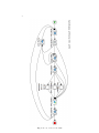
Automation of the ”Automated Teller Machine”
Case Study with YAWL
Andreas V. Hense and Robert Malz
Bonn-Rhein-Sieg University oAS
Grantham-Allee 20
53757 Sankt Augustin
Germany
Abstract. The workflow case study presented here is part of a comparative evaluation effort of paradigms and tools for business process
modelling. This paper provides a YAWL [6] specification for the case
study ”Automated Teller Machine” (ATM) [2]. Because an ATM is not
a typical business process, the implementation presented here consists of
a central server and ATMs as browser-based clients.
1
Introduction
Automated teller machines are usually associated with robust hardware, security
features, and complicated communication protocols. Real ATMs have a local
computer that operates its peripheral devices like screen, keyboard, pin-pad,
and card reader. Real ATMs are not implemented with workflow management
systems because there is no workflow.
According to Davenport, a (business) process is a ”specific ordering of work
activities across time and place, with a beginning, and end, and clearly identified
inputs and outputs: a structure for action.”[4] From the point of view of a bank,
an ATM performs a business process but a completely automated one. Typical
workflow management systems for the administrative domain like YAWL [6] are
best used in situations where the business process is only partially automated
and some human interaction is still necessary.
The reason why we have modelled an ATM using the workflow management
system YAWL is that this was a challenge in our comparative evaluation effort
of paradigms [3, 5].
A workflow management system always has one or more workflow engines [7].
An ATM together with a central database holding account information is a
distributed system with possibly unreliable communication over a wide area
network. The first question to be answered here is where to put the workflow
engine in this network. With real-life ATMs in mind and when reading the case
study [2] one might be tempted to place the workflow engine in the ATM. This
would mean that all activity is located in the ATM – ATM as client – and that
the central database is addressed like a server over the unreliable network. This
approach is possible and has indeed been the first attempt by the authors. One
2
Fig. 1. Process overview of the ATM
3
consequence of this approach is that every ATM runs a complete workflow engine
and nearly none of the functionality of the workflow management system is used.
Therefore, the authors have chosen to place the workflow engine next to the
central database. Also this approach does not use the full functionality of the
workflow management system: there is only a fixed number of ATMs and every
ATM runs exactly one case. However, it has the advantage of having only one
workflow engine for the whole system instead of having one workflow engine
per ATM. One consequence of this choice is that there is now a direct, reliable
connection between the workflow engine and the central database. The unreliable
communication is only from the engine to the ATMs. This approach is interesting
in so far as that the ATM can run browser-based as a thin client. Any changes
to workflows and user menus can be done centrally.1
2
Workflow for the Automated Teller Machine
In YAWL there are three perspectives that are clearly separated [6]:
The control flow perspective shows a superset of the possible traces of the
workflow. It is depicted in diagrams 1, 3, 4, and 5.
The resource perspective describes human or machine resources executing
the tasks depicted in the diagrams. It is described briefly in section 2.1.
The data perspective describes the data that pass between the tasks. This is
the topic of section 2.2.
Organisational information for the resource perspective is prepared using YAWL’s
control center. After that all three perspectives are edited with the YAWL editor.
Only the control flow perspective is displayed graphically.2
2.1
Control Flow and Resource Perspective
The workflow running on the workflow engine is depicted in figure 1. As already
stated above, the engine is placed next to the central database containing information on the accounts. One case – a workflow instance – is created for every
ATM. Each user interaction with the ATM goes through the diagram and finally
loops back: the case lasts as long as the ATM is operational.
The workflow contains three roles: ”ATM”, ”central database”, and ”codelet”.
The codelet role is an artificial one in our model. It serves the purpose of manually entering values that would otherwise be handled by an automated task.
Automated tasks are performed by Java classes called codelets in YAWL [6].
The communication between the ATM and the YAWL Engine is over the
wide area network that can have problems with stability and response times.
1
2
The full code of this example can be found here: http://www.bis.inf.hbrs.de/bpmcasestudies/
YAWL does not have a feature to display resources in diagrams. For the diagrams in
this paper the authors have chosen different icons to show the resource perspective.
These icons only serve documentation and do not influence workflow behaviour.
4
Fig. 2. Split Predicates for Task ”Enter PIN”
For that reason a workflow timer is implemented on all tasks that delegate to
the ATM – except the task ”Insert card”. If the timer expires the card holder
gets his card back or if the communication with the ATM fails the card will be
kept by the ATM.
The process starts with the task ”Insert card” which is delegated to the
corresponding ATM. When a customer inserts his card, the information on the
card will be read.3 In the second task ”Check card”, the central database gets
the information from the card and returns a value that decides on the path to
follow after the XOR-split. If the card is not readable – e.g. the customer inserts
a health card or the card is faulty – the ATM returns the card (task ”Return
card”). If the card is stolen, the next action of the ATM is ”Keep card”. When
a card is kept it is dropped somewhere inside the ATM. If everything is normal
the user is asked to enter the PIN.
The task ”Enter PIN” is equipped with a timeout. If communication over
the network is impossible or the user waits too long, the card is returned (task
”Return card”).4
If the customer enters a wrong PIN, a ”PINfailureCounter” is incremented in
task ”Increment counter” and the ATM returns to the task ”Enter PIN”. If the
”PINfailureCounter” has the value 3, the card is kept (task ”Keep card”). For
the check of the conditions there are split predicates which have to be written
in a combination of XQuery and XPath expressions (cf. figure 2). Next, for the
special case of the ”PINfailureCounter” there is an output binding needed which
checks if the PIN is correct in that case the counter doesn’t increment only if
the entered PIN is wrong. This binding is a combination of XQuery and XPath
(cf. listing 1.1).
3
4
We are not using external hardware here. Therefore, the card information will be
entered manually by the user.
A problem here is that ”Return card” cannot be executed by the ATM if the network
is unavailable. In that case, a correct card would be kept until the network is available
again. A solution to this problem might be an automatic returning of the card by the
card reader hardware after a given time. This problem is not solved in our model.
5
Listing 1.1. Output Binding for PINfailureCounter
i f ( / Enter PIN / PINentered / t e x t ()=/ATM/PIN/ t e x t ( ) ) then
/ Enter PIN / P I N f a i l u r e C o u n t e r / t e x t ( )
else
number ( / Enter PIN / P I N f a i l u r e C o u n t e r / t e x t ())+1
Only after entering a correct PIN the user gets the ”Select action” menu.
If the user does not select an action in time the card is returned. The possible
three choices of the user can be seen from the names of the following subnets.
If the customer wants to view the balance of his account, subnet ”View
balance” (cf. figure 3) is executed. In task ”Send balance” the central database
returns the balance of the account associated with the card. Next the ATM
gets the task ”View balance”. This task is equipped with a timeout in case of
communication problems or if the user does not acknowledge in time. The subnet
is finished after viewing the balance and the control flow goes back to the main
net.
Fig. 3. Process overview of ”View balance”
If the customer wants to withdraw cash, the workflow continues with the
subnet named ”Withdraw cash” (cf. figure 4). The subnet begins with the task
”Enter amount” which is assigned to the ATM. In case of a timeout the subprocess ends. Next, the central database gets the task ”get Balance for withdrawal”
and returns the balance of the corresponding account. After the central database
returns the balance, a codelet returns the minimum of the following three parameters: the first parameter is the current ”balance”. The second parameter is
the ”dailyLimit” minus ”amountWithdrawnToday”. The third parameter is the
”amountToWithdraw”. If the minimum value returned by the codelet is smaller
than the ”amountToWithdraw” the subnet ends. Otherwise, if enough money is
available, the ATM gets the task ”Dispense” which contains also a timeout for
communication problems. If the timeout executes the central database gets the
task ”Log dispense timeout”. Alternatively, if everything is in order, the central
database goes to task ”Debit account”. The last task in the subnet is ”Adapt
daily limit”. The daily limit is adapted on the credit card. For that task, there
is also a timeout for the same reason as before.
If the customer wants an account statement, the workflow continues with the
subnet named ”Ask for account statement” depicted in figure 5. In this subnet
6
Fig. 4. Process overview of ”Widthdraw cash’
7
the first task ”Send acknowledgement” is assigned to the role codelet. Next the
ATM gets the task ”Note reply” which informs the customer that the statement
will be sent. This task has a timeout for communication problems. After the
task, the subnet ends and the process continues with the main net.
Fig. 5. Process overview of ”Ask for account statement”
After the subnets are completed, the control flow is back in the main net of
figure 1 and the card is returned (task ”Return card”). Now the customer may
reclaim his card. If this is not done in time, the ATM will keep the card (task
”Keep card”). At the end, the process goes back to ”Insert card” again.
2.2
The Data Perspective
The process diagrams show how the tasks are interacting but how data are
handled by the tasks is not visible. In YAWL, there are two classes of variables:
net variables and decomposition variables. Decompostion variables are used in
tasks to populate forms that are presented to the user. Net variables are used
to exchange information between tasks. In the YAWL editor, decomposition
variables can be ”dragged and dropped” from net variables as shown in fig. 6.
From the definition in fig. 6, YAWL generates a JSP form as shown in fig. 7.5
In addition to a set of predefined primitive types, complex types can be
defined as shown in listing 1.2. YAWL uses XSD for data definitions.
Listing 1.2. Data Type Definition
<xs : schema xmlns : xs=”h t t p : / /www. w3 . o r g /2001/XMLSchema”>
<xs : simpleType name=”ActionMenuType”>
<xs : r e s t r i c t i o n b a s e=”xs : s t r i n g ”>
<xs : enumeration v a l u e=”No Action ” />
<xs : enumeration v a l u e=”View b a l a n c e ” />
<xs : enumeration v a l u e=”Withdraw c a s h ” />
<xs : enumeration v a l u e=”Ask f o r a c c o u n t s t a t e m e n t ” />
</xs : r e s t r i c t i o n >
</xs : simpleType>
<xs : simpleType name=”CardStatusType”>
5
Variable PINfailureCounter has been set to ”hidden”.
8
Fig. 6. Decomposition of the Task ”Insert card”
Fig. 7. Front End ”Insert card”
9
<xs : r e s t r i c t i o n b a s e=”xs : s t r i n g ”>
<xs : enumeration v a l u e=”Card OK” />
<xs : enumeration v a l u e=”Card not r e a d a b l e ” />
<xs : enumeration v a l u e=”Card s t o l e n ” />
</xs : r e s t r i c t i o n >
</xs : simpleType>
</xs : schema>
YAWL can generate forms from these definitions [1]. If a variable in a task is of
type ”ActionMenuType” of listing 1.2, YAWL will generate a drop down list as
shown in figure 8.
Fig. 8. Front End ”Select Action”
2.3
Enactment
Before executing the workflow, users and roles are created in the YAWL control
centre. The control centre is a web-based access to the YAWL resource service.
Figure 9 shows the control centre on a page where roles can be defined.
If the YAWL editor is connected to a running resource service each task can
be connected to a set of roles. Users who possess an appropriate role can then
work on the items offered to them. The finished workflow specification can be
uploaded to the YAWL engine.
3
Conclusion
As already stated in the introduction, we would not recommend YAWL for
the implementation of ATMs in practice. However, this modelling effort has
10
Fig. 9. Control centre of YAWL
yielded an executable prototype with which the functionality of an ATM can be
explained. The example also shows the limitations of a browser-based solution
for ATMs.
The process overviews are well-suited to explain the behaviour of an ATM
to a subject matter expert that is not familiar with programming. The process
overviews can thus bridge the gap between requirements and the software implementation – at least at the surface. The implementation of the ATM with
YAWL was easier than expected.
It is interesting to compare the YAWL process overviews with the modes of
the ASM and CSP models [3, 5].
References
1. M. Adams. YAWL - User Manual Version 3.0. The YAWL Foundation, 2014.
http://www.yawlfoundation.org.
2. Anonymous. Automatic teller machine or till: Case study, 2014. Formulated 1999
as Modelling in two formalisms: The FM99 ATM modelling challenge for the FM99
Conference and as A Cash-point Service Example in the IFAD document V6.3.0a,
reused 2013 for the Dagstuhl Seminar on Integration of Tools for Rigorous Software
Construction and Analysis to which A. Fleischmann added in 2014 the change and
cancel requirements.
3. E. Boerger and S. Zenzaro. Business process modeling for change via componentbased decomposition and ASM refnement. In Special Session on Comparative Case
Studies, Kiel, 2015. submitted for publication.
4. T. H. Davenport. Process Innovation: Reengineering Work Through Information
Technology. Harvard Business Review Press, Boston, Mass, Oct. 1992.
5. A. V. Hense. CSPm models for the ”automated teller machine” case study. In Special
Session on Comparative Case Studies, Kiel, 2015. submitted for publication.
11
6. A. H. M. ter Hofstede, W. M. P. van der Aalst, M. Adams, and N. Russell. Modern Business Process Automation: YAWL and its Support Environment. Springer,
Berlin, 1 edition, 2010.
7. WFMC. Workflow Management Coalition Terminology & Glossary, volume WFMCTC-1011. Workflow Management Coalition Specification, 1999.