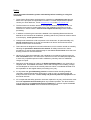
1
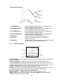
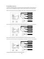
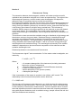
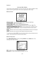
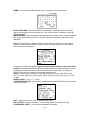
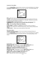
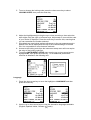
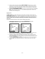
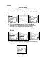
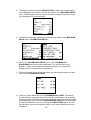
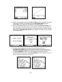
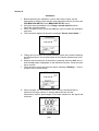
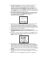
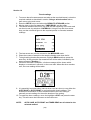
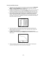
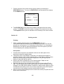
Fluorimeters
Models 6270, 6280 & 6285
Operating Manual
628 020/REV A/04- 06
Safety
This is important information; please read carefully before installing or using this
instrument.
1. The 62 Series Fluorimeters are designed for operation by trained personnel that are
aware of the principles and applications involved. For further help and advice please
contact your local distributor, e-mail [email protected] or visit www.jenway.com
2. The fluorimeter is a sensitive electronic and optical instrument designed for use in a
laboratory environment. Careful adherence to the installation instructions must be
observed. If in doubt contact a relevant and competent authority for advice before
proceeding.
3. In addition to observing the instructions detailed in the Operating Manual and Service
Manual for this instrument all installation, operating and service personnel must be aware
of, and employ, a safe system of work.
4. Voltage levels hazardous to life are present in this instrument, for personal safety only
trained engineers aware of the risk and avoidance of electric shock should remove
protective covers from the instrument.
5. This instrument is designed for minimal maintenance, which must be carried out carefully
following the procedures detailed in this manual. All safety instructions in these
procedures, as well as those defined locally for the area or environment where the work
is being carried out must be observed.
6. Other than for those items defined in the maintenance procedures herein there are no
user serviceable items in this instrument. Removal of covers and attempted adjustment
or service by unqualified personnel will invalidate any warranty and incur additional
charges for repair.
7. Reference should always be made to the Health and Safety Data for any chemicals or
reagents used. All available information, advice and warnings on the handling, storage,
use and disposal of such must be carefully observed. When not available this data must
be requested from the supplier before proceeding in any way.
8. It is important that good laboratory practice is observed when handling samples,
chemicals, reagents and ancillary equipment in order to carry out measurement and
analysis with this instrument. Suitable safety and personal protective equipment must
be used at all times.
9. If it is suspected that safety protection has been impaired in any way, the fluorimeter must
be made inoperative and secured against any intended operation. The fault condition
must be reported to the appropriate servicing authority. In all such reports the model
number and serial number of the fluorimeter must be quoted.
Contents:
Section 1
Introduction
Instrument description
Good practice guidelines
Section 2
Getting Started
Unpacking
Installation
Section 3
Fluorescence Theory
Section 4
Instrument Menu Options
Section 5
Instrument Settings
Instrument Lock
Date, Time and Language
Security
Operator ID
Section 6
Setting up a method
Section 7
Using a stored method
Section 8
Calibration
Section 9
Performing Measurements
Section 10
Timed Readings
Section 11
Saving Results
Section 12
Printing Results
Section 13
Maintenance & Troubleshooting
General and routine maintenance
Error codes and troubleshooting
Section 14
Accessories and Spares
Optional accessories
Section 15
Specification & Data
Technical specification
RS232 serial interface
Glossary of Terms
EC Declaration of Conformity
Section 1
Introduction
1.1
Instrument Description
Three models are available to cover a wide range of applications. The model 6280
covers the most sensitive determinations with emission wavelengths up to 650nm.
Where higher emission wavelengths will be utilised the model 6285 with its redenhanced detector is applicable. For less sensitive applications with a broader
wavelength range the model 6270 will meet the necessary requirements.
All three models offer intuitive operation with a user interface based on logical menus
that can be navigated from the simple keypad. Up to 20 methods can be created
without restriction and be saved for future use, they can also be locked against
accidental change by password entry, ensuring data integrity.
The permanent time and date tag on every stored reading further enhances Good
Laboratory Practice, while calibration reminders and operator identity can also be
entered to support conformance and traceability of operation.
With press-to-read operation and Total energy transfer (TET) technology the output
of the high-energy xenon lamp is maximised and its expected life extended so that it
should never need replacing in normal use.
The high quality optics is complemented by the Intelligent Filter Modules (IFM) that
can be identified by the system, this enables error messages to be generated and
displayed should the wrong filters be fitted or their positions be incorrect.
All models are powered from an external, universal mains adapter suitable for use
from 90Vac to 264Vac, while the 12V dc input enables use of the fluorimeters in
vehicles or from suitable battery packs.
Where temperature controlled fluorescence studies are necessary an optional
electrically heated sample holder is easily fitted while for continuous flow analysis an
external sipper pump and a wide range of flow through cuvettes are also available.
(1)
1.2
Good Practice Guidelines
1. The selection of the optimum excitation and emission wavelengths (filters) is
critical to achieving the best performance from the analysis.
2. All fluorimeters should be sited in a clean, dry, dust free environment. When in
use ambient temperature and light levels should remain as constant as possible.
3. Adherance to Standard Operating Procedures (SOP) and Good Laboratory
Practice (GLP) should be maintained, with regular calibration checks and a suitable
Quality Control (QC) programme.
4. The correct selection of cuvettes is imperative for accurate and reproducible
results:
a) Ensure all cuvettes used are compatible with fluorimetric measurements
where the emission beam is at 90° to the excitation source. Typical examples
have 4 clear sides.
b) Ensure any native fluorescence from the cuvette material is minimal at the
analysis wavelengths.
c) Plastic cuvettes should be used once only.
d) Glass and quartz cuvettes should be thoroughly cleaned after use. Discard
when scratches or marks are evident in their optical surfaces.
e) Ensure any cleaning agents used do not fluoresce at the analytical
wavelengths and are thoroughly rinsed away before drying.
f) Ensure the cuvettes used are compatible with the constituents of both the
samples and standards they are to hold. Plastic cuvettes are not compatible
with some organic solvents.
g) Cuvettes must be handled with care; by the top and non-optical surfaces only.
Any finger marks must be removed by using a suitable cleaning process.
h) Flow through cuvettes must be selected with additional consideration for the
sample type, aspirated volume, pumping system and rinse cycle, as well as
the waste handling to be used.
5. The high sensitivity of fluorimetric analysis means that all glassware used in the
preparation of samples and standards must be totally free from contamination.
6. Chemicals and reagents used in sample and standard preparation should be of
the highest grade of purity (AR Grade) and all should be checked for excessive
background fluorescence at the analytical wavelengths.
7. Samples and working standards should not be stored due to the effects of
evaporation, as well as chemical and photo-degradation. Only prepare samples and
working standards when they are required for analysis.
8. Fluorescence is inversely proportional to temperature. Ensure that all samples
and standards have equilibrated to ambient temperature before analysis. If in doubt,
use a temperature controlled cuvette holder.
9. Refrigerated or cold samples will form micro-bubbles on the cuvette wall as they
warm up. These are a common cause of drift in readings. Ensure all samples and
standards have equilibrated to ambient temperature before analysis.
(2)
10. Check the linear range for each method and, where necessary, use a multi-point
calibration or calibration curve.
11. Be aware of the effects of quenching and, where necessary, use sample dilution
or extraction methods to eliminate this.
12. Monitor the blank during and between batches to identify any increase due to
contamination.
13. Sources of contamination to be considered include cleaning agents, microorganisms, particles in suspension, stop-cock grease, filter paper residues and
plasticisers leached from containers, caps or sealing materials.
14. Many fluorescent assays are pH dependent. Ensure the pH of all samples and
standards is within specified limits before carrying out the analysis.
(3)
Section 2
Getting Started
2.1
Unpacking
Remove the universal 12V power supply (with UK, US and EU leads) and the pack of
100 disposable cuvettes from the packaging.
Remove the fluorimeter from the carton by lifting it in the centre between the two
support cheeks; do not lift it by the support cheeks.
Place all items on a clean workbench then remove the support cheeks and the
polythene bag from the fluorimeter.
Any shortages or damage must be reported to your local distributor or the
manufacturer as soon as possible.
Keep all packing materials in case the unit has to be re-shipped at a later date.
It is important that when re-packing the instrument it is first sealed in a strong, clean
polythene bag to protect it from the dust and particles that are present in all packing
materials.
2.2
Installation
2.21 Location
In ideal circumstances the installation environment will be clean, dry and dust free
with the instrument protected from extreme variations in ambient lighting and
temperature change. For field use it is recommended that the instrument is used in
the optional storage case for additional protection.
Where conditions are less than ideal, maintenance and cleaning must be carried out
regularly and additional protection offered where possible. The optional dust cover
should always be fitted when the unit is not being used or is stored for short periods.
2.22 Supply Voltage
The fluorimeter is powered by a low voltage dc power supply that operates from a 90264Vac mains supply. The universal power supply is supplied with 3 mains leads for
UK, EU and US sockets. The correct lead for your supply should be selected.
2.23 Mains Connections
The leads supplied have a moulded on plug. However, if this is removed for any
reason the wires in the mains lead are colour coded to conform to the internationally
recognised standard such that:
UK CONNECTIONS
BROWN
LIVE
BLUE
NEUTRAL
GREEN/YELLOW
EARTH
US CONNECTIONS
BLACK
LIVE
WHITE
NEUTRAL
GREEN
EARTH
Safety
When disposing of any removed plug the connectors must be removed or
made incapable of insertion into a mains socket.
(4)
2.24 Keypad Functions
3
1
4
2
7
5
6
1. UP ARROW key 2. DOWN ARROW key 3. LEFT ARROW key 4. RIGHT ARROW key 5. ENTER key 6. CAL key 7. PRINT key -
2.25
used to navigate through menus, to increase values
and for paging up in stored results.
used to navigate through menus, to decrease values
and for paging down in stored results.
used to navigate through menus and to highlight the
selected digit when setting values.
used to navigate through menus and to highlight the
selected digit when setting values.
used to accept the highlighted menu option.
initiates a calibration sequence from within the
measurement mode.
initiates a print from the measurement display or stored
results. Sends data to RS232 serial port.
Instrument Display
1
2
3
4
5
6
1. Method Name - this will appear on all measurement screens, with the exception of
Raw Fluorescence.
2. Results display - provides direct readout of standards and sample results.
3. Units of measure - shows selected measurement units: ppm, RFU, U/ml, mU/l,
U/l, µM/l, mM/l, M/l, µg/ml, mg/ml, µg/dl, mg/dl, g/dl, ng/l, µg/l, mg/l, g/l, none, %, ppb
4. Status message - shows the current instrument status, such as reading … or
printing … and provides a reminder when calibration is due.
5. Gain - shows the current photomultiplier tube gain setting (0-100%). Gain should
be optimised either manually or by using auto set gain for each method.
Note: This option is not available on the Model 6270.
6. Menu Options - EXIT - allows the user to return to the main menu,
READ - press read to read the sample or standard, SAVE - saves the currently
displayed result to instrument memory
(5)
2.26
Rear Panel Layout
1.
Output Socket – 9 way output socket for RS232
2.
Switch – Power On/Off switch
3.
Connection Sockets – 4 x pin sockets for heated cell block controller.
4.
Power In Socket – Connection socket for 12V DC universal mains adapter
2.27
Sample Chamber Filter and Cuvette Positioning
(6)
2.28
Power on and Self-Tests
Connect the mains supply cable to the rear panel mains input socket and plug the
other end into a suitable mains supply socket.
Lift the sample chamber lid on the instrument and ensure that there is no sample or
other item present in the sample holder, close the lid.
Switch on the supply socket, then the instrument, using the Power switch located on
the rear panel.
The instrument will then perform a power on self-test protocol. The following screen
will be shown for approx. 3 seconds:
Please ensure
sample chamber
door remains
closed during
power on tests
Followed by:
On successful completion of these tests the Main Menu screen will be displayed.
For optimum performance a 10-minute warm-up period is required if the ambient
temperature is below 10°C. The unit must be re-calibrated and sample measurement
repeated if this calibration check shows excessive drift.
Should a problem occur during the self-tests an information box or error support
message will be displayed. For assistance please refer to the troubleshooting section
in this manual.
(7)
Example Menu Operation
A common operating system is used throughout this and similar Jenway products, a
brief overview of navigating through the menu system with the cursor keys follows;
Use the up and down arrow keys to highlight a menu option, press the enter key to confirm.
Left arrow
Up arrow key
Right arrow
Down arrow
Enter key
Use the right and left arrow keys to select a digit for adjustment with the up and down arrow
Left arrow
Up arrow key
Right arrow
Down arrow
Enter key
keys, press the enter key to confirm the setting when ALL digits have been correctly set.
Use the up or down arrow keys to browse through pre-set options, when the correct selection
Left arrow
Up arrow key
Right arrow
Down arrow
Enter key
is displayed press the enter key to confirm your choice.
(8)
Section 3
Fluorescence Theory
The interaction between electromagnetic radiation and matter provides a useful,
qualitative and quantitative analytical tool, known as spectroscopy. The region of the
electromagnetic spectrum, to which matter under investigation is subjected to,
defines the type of transitions that occur within the molecules.
Fluorimetry uses radiation from the UV-Vis region of the electromagnetic spectrum to
study transitions between electronic levels in a molecule or atom. The absorption of
energy from light radiation (photons) by a molecule or atom, promotes electrons from
a low energy ground state to a higher energy excited level. This is known as
excitation and the amount of energy transferred to the molecule or atom will depend
on two main factors. The composition of the matter under investigation and the
energy and wavelength of the radiation, have a significant effect on the transitions of
electrons.
The molecule or atom converts the excitation energy to vibrational or light energy and
the electron returns to its ground state. Vibrational energy is transferred through
movement and collision with other molecules, but energy not lost in this way is
released as light radiation. The light emission is known as fluorescence and if some
energy has been removed through vibration, it will be of a lower energy and longer
wavelength than the excitation energy. The wavelength and intensity of the emitted
radiation is dependent on the structure and composition of the molecule and the
excitation wavelength used.
Relationship between concentration and fluorescence
The fluorescence signal F and concentration C of the matter under investigation, are
related by:
F = KQP0 (1-10-
εbC
)
Where
K
Q
P0
ε
b
= A constant characteristic of the instrument (Including instrument
electronics, pH and Temperature)
= Quantum efficiency (= Photons emitted/Photons absorbed)
= Power of incident radiation
= Molar absorptivity of the species (matter)
= Absorption path length
If the concentration of the matter in question is low (dilute), εbC is small. The
relationship is then linear and the equation can be written as
F = 2.3KQP0 εbC
The accuracy of fluorescent measurements is very high because the radiant energy
being formed is measured directly. There are also only a few, easily controlled limits
on the sensitivity of fluorescence measurements. From the equation above it can be
seen that adjustments made to instrument electrical noise and competing radiations,
along with physical limitations such as radiation energy, sample volume and cell size
affect the measurement sensitivity.
(9)
Section 4
Instrument Menu Options
In this section a brief explanation is given for the main menu options available. These
will be covered in greater depth in the sections appropriate to their usage.
Measure Screen
METHOD NAME - user set current method name or DEFAULT METHOD
LAST READING - result from last read or --.--UNITS OF MEASURE - as set in MEASURE SETUP menu
SYSTEM GAIN% - 0 to100% as set up in MEASURE SETUP menu. Note: This
option is not available on the Model 6270.
CALIBRATION REMINDER (flashing) - user alert indicating that a calibration is due
TIMED READING COUNTDOWN - number of seconds until the next auto read is
performed
READ – allows the user to take a reading of sample/standard currently in the sample
chamber
SAVE – allows the user to save the last reading to instrument memory
To exit this menu highlight EXIT using the right and left arrow keys and press enter to
confirm. This will return you to the main menu options.
Measure Setup menu
Enter MEASURE SETUP menu by selecting SETUP from the MAIN menu. The
following screen will be shown:
EXIT – allows user to return to the previous menu
METHOD ID – used to index individual methods. (0 to 19)
(10)
NAME – user entered method name (up to a maximum of 19 characters)
EXCITATION NM – user set excitation wavelengths. Actual filter data is checked
against this setting during measurement. If an incorrect filter is detected a warning
will be displayed.
EMISSION NM – user set emission wavelengths. Actual filter data is checked against
this setting during measurement. If an incorrect filter is detected a warning will be
displayed.
Note: If the excitation or emission filter modules do not match the current method
settings on entry to the measure mode (or prior to taking a reading or calibration)
then a warning is displayed:
A scrolling message will appear ‘please change method setting or fit correct filter
module’. No measurements can be performed until this has been corrected. If a filter
is missing the instrument will not allow measurement to take place. Pressing the
EXIT key will return the screen to the setup menu options.
UNITS – allows user to select the units appropriate to the test. ppm, RFU, U/ml,
mU/l, U/l, µM/l, mM/l, M/l, µg/ml, mg/ml, µg/dl, mg/dl, g/dl, ng/l, µg/l, mg/l, g/l, none,
%, ppb
RESOLUTION – 0.01, 0.1, 1, 0.001
CALIBRATION SETUP – this menu is not displayed when RFU (Raw Fluorescence)
units are selected.
EXIT – allows the user to return to the previous menu
NO OF STDS – allows selection of 1-6 standards (blank is always included)
STANDARDS TABLE – user entered calibration standards
(11)
FLUORESCENCE TABLE – shows results of last calibration RFU (raw fluorescence)
values. Tabular and graphical displays available
P.M.T GAIN(%) - 0 to 100% gain setting for system photomultiplier tube. Note: This
option is not available on the Model 6270.
AUTO SET GAIN - uses the highest user entered calibration standard to
automatically set the PMT gain to give as close as possible to 95% full scale
emission signal. Note: This option is not available on the Model 6270.
CAL REMINDER - enables or disables the measure mode prompt to calibrate at the
set calibration interval
CAL INTERVAL(HRS) - the number of hours between calibrations can be user set
from 1-999 hours.
Results Storage Menu
From the MAIN MENU press the down arrow key to move the highlight on the display
to cover RESULTS STORAGE, then press the enter key. The following display will
be shown:
EXIT - allows the user to return to the previous menu
TIMED READ - enables automatic measurements to be taken at a set interval when
in measure mod
INTERVAL - time interval between the end of one reading and the automatic start of
the next reading in seconds
AUTO SAVE - when enabled, automatically saves to instrument memory after each
reading is performed (either manually or timed)
AUTO PRINT - when enabled, automatically prints to RS232 connected device after
each reading is performed (either manually or timed)
(12)
Instrument Setup Menu
From the MAIN MENU press the down arrow key to move the highlight on the display
to cover INSTRUMENT SETUP, then press the enter key. The following display will
be shown:
EXIT - allows the user to return to the previous menu
LOCKED - when enabled, prevents access to set up menus without the PIN code
(settings of current method to be viewed but not changed). Calibrations can still be
performed when the instrument is locked.
LOCKING CODE - 3 digit code that must be entered to unlock the instrument
LANGUAGE - choice of English, French, German, Italian and Spanish
TIME - set to time stamp readings and calibrations
DATE – set to date stamp readings and calibrations
DATE FORMAT - DD/MM/YY or MM/DD/YY (If the date format is changed to
MM/DD/YY the changes are reflected straight away). Used to identify saved/printed
results
OPERATOR ID – 3 digit code can be entered from 000 to 999
Filter Status Menu
This menu provides a summary of the current method wavelength setting and
excitation and emission filters.
From the MAIN MENU press the down arrow key to move the highlight on the display
to cover FILTER STATUS, then press the enter key. The following display will be
shown:
EXCITATION - wavelength in nm of current excitation filter
METHOD SETTING - wavelength in nm set in MEASURE SETUP menu
FILTER TYPE - 3 types of filter are available: BP = Bandpass,
COL = Cut-Off Longpass and NPB = Narrow Bandpass
PART NO - Jenway part number of filter module
EMISSION - wavelength in nm of current emission filter
METHOD SETTING - wavelength in nm set in MEASURE SETUP menu
FILTER TYPE - 3 types of filter are available: BP = Bandpass,
COL = Cut-Off Longpass and NPB = Narrow Bandpass
PART NO - Jenway part number of filter module
EXIT - allows the user to return to the previous menu
(13)
Section 5
Instrument Settings
Note: Using the left arrow key to move from the settings on the right hand side
of the menu will abort any adjustments you have made and return the value
or selection to its previous settings. The enter key must be used to confirm
any changes.
All settings listed below are accessed from the INSTRUMENT SETUP menu as
shown below:
The 62 Series Fluorimeters offer a number of important functions to control or restrict
use of the instrument. This can be useful in developing GLP procedures or for
controlling usage in multi-user installations.
The instrument LOCKING CODE restricts access to the set up menus without the
entry of a 3 digit security code. When the LOCKED function is enabled, settings can
only be viewed, not changed. Calibrations can still be performed when the instrument
is locked.
Instrument Lock
1. Use the down arrow key to select LOCKED from the menu and press the
enter key.
2. The instrument lock can be turned on or off using the up or down keys. Press
enter to confirm your selection.
3. With the instrument lock set to Off all functions of the instrument are available
to all users.
4. With the instrument lock set to On all methods will be locked without the entry
of a locking code.
(14)
5. To set or change the locking code, press the down arrow key to select
LOCKING CODE, then press the enter key.
6. Adjust the highlighted digit using the up or down arrow keys, then select the
other digits using the right or left arrow keys. Adjust each in turn until the code
of your choice is displayed. Press the enter key to confirm this, ensuring that
you can remember the number selected.
7. All methods are now locked against adjustment to the set parameters and a
padlock icon will be displayed at the top of the method settings to indicate
this. It is not possible to move between methods.
8. Access to the locking code from the instrument setup menu will now require
the entry of the locking code first.
9. To exit the INSTRUMENT SETUP menu use the up or down arrow keys to
highlight EXIT, then press the enter key. To set additional parameters
continue as detailed in the following text.
Language
1. Press the down arrow key to move the highlight to LANGUAGE and then
press the enter key.
2. Use the up or down arrow keys to view the alternative languages available
(English, Spanish, Italian, German or French).
(15)
3. When the language of your choice is highlighted press the enter key to
confirm. The language used on the display will now be changed to match your
choice.
4. To exit the INSTRUMENT SETUP menu use the up or down arrow keys to
highlight EXIT, then press the enter key. To set additional parameters
continue as detailed in the following text.
Time
1. Press the down arrow key to move the highlight to TIME and press the enter
key.
2. Use the up and down arrow keys to set the highlighted digit of the time to the
correct value. Use the right and left arrow keys to highlight each digit in turn
for adjustment with the up and down keys until the correct time is set.
3. Press the enter key to confirm the settings and start the clock running from
the set value.
Note: The clock can only be set in the 24-hour system, i.e; 1.00 p.m. =
13.00.00
4. To exit the INSTRUMENT SETUP use the up or down arrow keys to highlight
EXIT, the press the enter key. To set additional parameters continue as
detailed in the following text.
Date
1. Press the down arrow key to highlight DATE, then press the enter key.
2. Use the up and down arrow keys to set the highlighted digit of the date to the
correct value. Use the right and left arrow keys to highlight each digit in turn
for adjustment with the up and down arrow keys until the correct date is set.
3. Press the enter key to confirm the setting and start the date running from the
set value.
(16)
4. Use the down arrow key to select DATE FORMAT. Press the up or down
arrow keys to view the two alternative date formats. Press the enter key to
confirm your choice. The previously set date will automatically change with
your selection in this menu option.
5. To exit the INSTRUMENT SETUP use the up or down arrow keys to highlight
EXIT, then press the enter key. To set additional parameters continue as
detailed in the following text.
Operator ID
OPERATOR ID is a 3-digit code that can be quickly and easily entered from the
INSTRUMENT SETUP menu. This ID will appear in the header of all results printed
or down loaded from the fluorimeter, identifying the operator that carried out the
analysis. When using this facility all potential users should be allocated individual 3
digit codes.
Operators should enter their code using the following procedure:
1. Use the up or down arrow keys to select OPERATOR ID from the
INSTRUMENT SETUP menu, then press the enter key.
2. Use the right or left arrow keys to highlight each digit in turn. Use the up or
down arrow keys for adjustment until the new operator ID is set.
3. Confirm the operator ID by pressing the enter key. This current ID will be
used in the header of all result printouts and results data transferred to a PC
or other serial device.
4. To exit the INSTRUMENT SETUP menu use the up or down arrow keys to
highlight EXIT, then press the enter key. This will return you to the main
menu.
(17)
Section 6
Setting up a method
1. Enter MEASURE SETUP menu by selecting SETUP from the MAIN menu.
2. Select a suitable METHOD ID (0-19).
3. Give the method a NAME (up to 19 characters) using the alphanumeric
screen accessed by selecting the NAME option of the MEASURE SETUP
menu.
4. Return to the MEASURE SETUP menu and set the EXCITATION
wavelength, in nm for the test you wish to perform. The excitation filter
module fitted for this test will need to be the same wavelength.
5. In the same way set the EMISSION filter wavelength, ensuring this is the
same wavelength as the emission filter module.
6. By scrolling through the available units, select the required UNITS OF
MEASURE.
7. If you wish to make raw fluorescence measurements, then select RFU from
the units of measure. If RFU is used, then there is no need to calibrate before
taking measurements so the CALIBRATION SETUP menu (at the bottom of
the MEASURE SETUP menu) is removed.
(18)
8. The number of decimal places (RESOLUTION) to which the measurements
will be displayed can then be set at the next option in the MEASURE SETUP
menu. The fluorimeter will auto range resolution for measurements too large
to be displayed in the set resolution.
9. To define the calibration parameters, select the last option of the MEASURE
SETUP menu, CALIBRATION SETUP.
10. Once in the CALIBRATION SETUP menu, set the NUMBER OF
STANDARDS that will be used at calibration. The number can be set
between 1 and 6, but this does not include the blank (no fluorescence)
standard, which is required for all calibrations.
11. The concentration values of the standards (not including the blank) can then
be set in the STANDARDS TABLE.
12. The menu option below this is the FLUORESCENCE TABLE. The default,
raw fluorescence values will be shown here until a calibration is successfully
completed. Once a calibration has been performed, the raw fluorescence data
will be displayed here. From the FLUORESCENCE TABLE it is also possible
to view the calibration curve, by choosing the VIEW CURVE option. As with
the data table, this will show default values until a valid calibration has been
completed.
(19)
13. Set the photomultiplier tube gain (P.M.T. GAIN %) to the required percentage,
for this test, if known. If not known, use the AUTO SET GAIN option as
below. Note: This option is not available on the Model 6270.
14. To find the optimum gain for a given test, select the AUTO SET GAIN menu
option and follow the instructions on the instrument screen. If you accept the
gain suggested by the instrument, this will then automatically update the gain
setting in the CALIBRATION SETUP menu. Note: This option is not available
on the Model 6270.
15. To ensure that calibrations are regularly performed the final two
CALIBRATION SETUP menu options can be employed. If you wish for a
calibration reminder to appear in the measure screen, at regular intervals set
the CAL REMINDER to On. The interval between calibration and the
reminder being shown is set using CAL INTERVAL to the required number of
hours using the up and down arrow keys.
(20)
16. The method is now fully set and will be the available in the MEASURE
screen.
Section 7
Using a stored method
1. From the MAIN menu, select the SETUP menu and then MEASURE
SETUP.
2. By setting the METHOD ID to the appropriate number (0-19) the saved
parameters such as the method name and wavelengths will appear and
be ready for use.
3. EXIT the setup menus and return to the MAIN menu.
4. Ensure that the excitation and emission filters, appropriate to selected
method, are fitted in the sample chamber.
5. Enter the MEASURE mode.
6. The name of the selected method will be shown at the top of the screen,
with the PMT gain % as set for that method also displayed. Note: This
option is not available on the Model 6270.
7. No concentration will be shown as no measurement has been taken, but
the selected units of measure will be displayed.
(21)
Section 8
Calibration
1. Before beginning the calibration, ensure that close to hand, are the
appropriate cuvette/s, blank solution and standard solutions (as set in the
CALIBRATION SETUP of the MEASURE SETUP menu).
2. Using the steps as detailed in the 'Using a stored method' section,
select the required method.
3. Once in measure mode, press the CAL key once to initiate the calibration
sequence.
4. The instrument display will show the message "Please insert blank…"
5. Taking care not to mark the optical surfaces, place the cuvette containing
the blank solution in the cuvette holder of the sample chamber and close
the lid.
6. Measure the fluorescence of the blank by pressing either the CAL key or
with the CAL option highlighted on the instrument screen. Press the enter
key to confirm.
7. The instrument screen will show the status message "Reading…" for the
duration of the measurement.
8. Once complete, the concentration (zero, as this is the blank) will be
shown as the large number on screen. Below this are the raw
fluorescence and the percentages of full-scale emission for the signal and
reference.
(22)
9. The options at the bottom of the screen will have also changed. The
ACCEPT and REPEAT options relate to the calibration step just
completed. If the concentration and other data from the calibration are
correct and satisfactory, select ACCEPT to continue through the
calibration sequence to the first standard. If the previous step has given
unacceptable figures, then select REPEAT and perform the previous step
again. ABORT allows the whole calibration sequence to be cancelled and
the instrument to return to the measure screen.
10. Once the blank calibration has been accepted, the instrument will display
the message "Please insert standard x.xxx" and the concentration of
the first standard, as set in the STANDARDS TABLE of the
MEASURE/CALIBRATION SETUP.
11. Remove the cuvette of Blank solution from the sample chamber, replace
with a cuvette of the requested standard and close the lid. If using
reusable cuvettes, ensure that proper cleaning procedures are employed
to make certain that there is no carry over of solutions or contamination.
12. As with the blank, calibrate the instrument with this first standard by using
the CAL option on screen or CAL key.
13. As with the blank, the concentration of the standard (as set in the
STANDARDS TABLE) will be shown on screen with the raw
fluorescence and the percentages of full-scale emission for the signal and
reference.
14. Once again, review this data and if acceptable use the ACCEPT option to
move on to any further calibration standards in the same way. If not the
REPEAT function can be used.
15. The sequence of calibrating with each standard will continue in this
fashion (points 10-13) until each standard that has been set, has been
used. At this point the instrument will give a summary of the calibration by
displaying the raw fluorescence for each standard in a table. An option to
view the calibration curve, a plot of the concentration of the standards
against their raw fluorescence, is given at the bottom of the screen (VIEW
CURVE).
16. On exiting the calibration summary the instrument is returned to the
measure screen and the status message "Cal required…" will have been
removed.
17. Measurements of unknown concentration samples can now be made.
(23)
Section 9
Performing measurements
1. Using the steps as detailed in the 'Using a stored method' to select the
required method.
2. Prior to taking any measurements make certain that the correct excitation or
emission filter modules are fitted and that a valid calibration (as detailed in
Section 8) has been completed.
3. Before taking any measurements it is worth considering the utilisation of
functions such as AUTO SAVE and AUTO PRINT to provide easy access
and analysis of results at a later time. These are fully explained in the
following section 'Saving results' and 'Printing results'.
4. If readings are required at regular timed intervals, the TIMED READ facility
can be applied. The use and setting of this is detailed separately in section
'Timed readings' below.
5. Once in measure mode, place the sample (solution of unknown
concentration) to be measured into the cuvette holder of the sample chamber
and close the lid.
6. Move the on screen highlight, using the left and right arrow keys, to the READ
option and press the enter key.
7. A status message "Reading…" will be shown throughout the duration of the
measurement.
8. Once the measurement is complete, the calculated concentration of the
sample will be shown, at the resolution and with the units of measure as set in
MEASURE SETUP.
9. This measurement can then be saved or printed as detailed in the sections
below entitled 'Saving results' and 'Printing results'.
10. Further measurements can be taken by use of the READ option.
NOTE:
AUTO SAVE, AUTO PRINT and TIMED READ are all related to the
selected method.
(24)
Section 10
Timed readings
1. To ensure that all measurements are taken at the required interval, select the
required method as described in section 'Using a stored method' above,
then return to the main menu.
2. Enter the SETUP menu and select the RESULTS STORAGE section.
3. Moving down to the first parameter, TIMED READ, set this to On.
4. The interval between the end of one read and the beginning of the next read
can then be set, by selection of INTERVAL. Using the up and down arrow
keys, set the numerical figure to the required period, in seconds, between
readings.
5. The instrument can now be returned to the MEASURE mode.
6. Place the cuvette of sample in the sample chamber and close the lid.
7. To begin taking timed measurements, highlight READ and then press the
enter key. At this point the first measurement will be taken, indicated by the
status message "Reading…".
8. Once this first read is complete, a further message will be shown which
displays a countdown in seconds, to the next read. When this timer reaches
zero, the next reading will be taken.
9. It is especially important when interval times used are short; to use either the
AUTO SAVE or AUTO PRINT in conjunction with timed readings. This
enables full automation of result collection without the user having to
manually record readings for the entire duration of the testing.
10. To cease the timer readings, move the highlight to EXIT and press the enter
key. This will return the instrument to the main menu.
NOTE:
AUTO SAVE, AUTO PRINT and TIMED READ are all related to the
selected method.
(25)
Section 11
Saving results
Saving results
1. When a reading has been taken in the MEASURE mode, the concentration
result is displayed on screen and can be saved to the instrument internal
memory by selecting the SAVE option on the right hand side of the
MEASURE screen. To confirm the save is successful the message "Result
Saved…" is shown briefly on screen.
2. A maximum of 100 results can be saved in this way, for each method. If more
than 100 results are required, the results area must be cleared before the
101st result is taken. Please see section "Stored results/Results mode" for
details of how to achieve this.
Auto save
1. To remove the need to manually select SAVE after each result, AUTO SAVE
can be activated. After every read operation, either timed or manual, the
concentration will be automatically saved.
2. To ensure every result is saved, select the required method as detailed in
'Using a stored method' and then return to the MAIN menu.
3. Enter the SETUP menu and select the RESULTS STORAGE section.
4. Move to AUTO SAVE and set to On.
5. Using the EXIT options, return to the MAIN menu and then move to the
MEASURE screen.
6. Each read operation will now have the result automatically saved and this is
indicated on screen by the status message "Result saved…"
7. A maximum of 100 results can be saved in this way, for each method. If more
than 100 results are required, the results area must be cleared before the
101st result is taken. Please see section "Stored results/Results mode" for
details of how to achieve this.
(26)
Stored results/Results mode
1. To access the saved results for the method currently selected in MEASURE
SETUP, return to the MAIN menu. Using the down arrow key, move the
highlight to RESULTS and press the enter key.
2. A table of all saved results, for the method named at the top of the screen will
be shown along with the time at which the READ operation occurred. The
results are presented in chronological order, beginning with the most recent.
3. If the number of stored results exceeds seven, a small down arrow will be
shown on the right hand side of the screen to indicate further screens of
results. These other results are accessed by use of the down arrow key. The
full range of results can be viewed by use of the up and down arrow keys to
move to the screen of interest.
4. The Clear function on this screen will remove ALL stored results for the
Method named at the top of the screen. Once Clear has been utilised, the
results cannot be recovered.
5. A graphical representation of the stored results plotted against time is
available. This is accessed by the GRAPH option at the bottom of the results
table screen.
6. The first (earliest) result is set as time zero and the times of subsequent
results are calculated from this, but purely for the graph.
(27)
7. Further analysis of the saved results can be made by accessing the
STATISTICS screen. To move to STATISTICS, use the option at the bottom
of the GRAPH screen.
8. The STATISTICS screen shows two numbers calculated from the saved
results. The SLOPE reveals the extent of change of fluorescence over time.
The R-squared value gives an indication of the linearity of the saved results.
Section 12
Printing results
Printing
1. When a reading has been taken in the MEASURE mode, the
concentration/raw fluorescence result is displayed on screen. This can be
printed to a serial printer or PC if attached via the RS232. The fluorimeter is
designed for use with the optional accessories of the Porti printer (P/N 037701) or DataWay PC software (P/N 050-501).
Porti printer
1. Connect the Porti printer to the RS232 socket on the back panel of the
instrument using the supplied cable.
2. The printer can be used without connection to a mains power supply for
periods of time by means of the integral battery. If the battery is low or mains
power is preferred, plug in the power supply pack using the appropriate
cables, as provided with the printer.
3. Ensure the printer is fitted with a roll of thermal paper. Paper can be
advanced by use of the Feed button on the printer.
4. Switch on the printer with the black button and the left hand side LED will
light. The LED will be green when mains power is used or the battery is well
charged. If the LED shows flashes of red and no mains power supply is used,
this indicates the battery level is low. Further instructions on the Porti printer
can be found in the operator manual included with the printer.
5. Now to print the result displayed on the instrument screen just press the Print
button on the fluorimeter.
(28)
DataWay
1. Connect the supplied cable between the PC and the instrument RS232
socket.
2. If using for the first time, insert the DataWay CD into the CD drive of the PC.
The CD will automatically run and installation instructions will be shown on
the PC screen.
3. Once installed the software can be opened either from the programs menu or
with the DataWay icon on the PC desktop.
4. Open the DataWay software. A pop-up box will appear as the software starts
up. Tick the box to the left hand side of the instrument model number and
then press the search button.
5. When the software has found the attached instrument, the right hand side
'Connect' button will be available. Click on this to connect DataWay.
6. Once connected, click the 'Ok' and DataWay will fully open.
7. For further help or greater detail on using DataWay, please consult the
DataWay help file.
8. Click on the Data Manager tab of the DataWay screen.
9. Now to print the result displayed on the instrument screen just press the Print
button on the fluorimeter or the ‘take reading’ button in DataWay.
10. For instruction on saving data, plotting graphs and other features of DataWay,
please consult the DataWay help file.
Auto print
1. To remove the need to manually select PRINT after each result, AUTO
PRINT can be activated. After every read operation, either timed or manual,
the concentration will be automatically printed.
2. Select the required accessory to which to print results to and setup as
detailed above in either the 'Porti printer' or 'Dataway' section.
3. To ensure every result is printed, select the required method as detailed in
'Using a stored method' and then return to the main menu.
4. Enter the setup menu and select the results storage section.
5. Move to AUTO PRINT and set to On.
6. Using the EXIT options, return to the main menu and then move to the
MEASURE screen.
Each read operation will now instigate the result being automatically printed,
to the connected device.
(29)
Section 13
Maintenance & Troubleshooting
8.1
General
The 62 Series Fluorimeters are designed to give optimum performance with minimum
maintenance. It is only necessary to keep the external surfaces clean and free from
dust. The sample area should always be kept clean and any accidental spillage
should be wiped away immediately.
To give added protection when not in use, the unit should be disconnected from the
mains supply and covered with the optional dust cover (630 028).
For longer-term storage or re-shipment it is recommended that the unit be returned to
the original packing case.
8.2 Xenon Lamp Replacement
In the highly unlikely event of lamp failure it will be necessary to contact your local
distributor or service agent for assistance. There are no serviceable parts within this
product. Under no circumstances should any attempt be made to effect repair as this
will invalidate the product Warranty.
(30)
Section 14
Optional Accessories
14.1
Accessories
Bandpass Filters
627 126
UG1
627 124
BG28
627 125
VG9
320-380nm
380-500nm
480-580nm
Cut-off Filters (low cut, transmission blocked below stated wavelength)
627 127
Kodak 29
610nm
627 128
Ilford 201
545nm
627 129
Kodak 8
475nm
627 130
Kodak 2B
395nm
627 131
Glass
305nm
Interference Filters (10nm bandpass)
627 141
Wavelength 250nm
627 132
Wavelength 254nm
627 142
Wavelength 260nm
627 143
Wavelength 265nm
627 144
Wavelength 270nm
627 145
Wavelength 280nm
627 146
Wavelength 290nm
627 147
Wavelength 295nm
627 148
Wavelength 300nm
627 149
Wavelength 305nm
627 150
Wavelength 310nm
627 151
Wavelength 313nm
627 152
Wavelength 320nm
627 153
Wavelength 326nm
627 154
Wavelength 330nm
627 155
Wavelength 334nm
627 156
Wavelength 337nm
627 133
Wavelength 340nm
627 140
Wavelength 350nm
627 157
Wavelength 360nm
627 138
Wavelength 365nm
627 158
Wavelength 370nm
627 134
Wavelength 380nm
627 159
Wavelength 390nm
627 135
Wavelength 400nm
627 160
Wavelength 405nm
627 161
Wavelength 410nm
627 162
Wavelength 415nm
627 163
Wavelength 420nm
627 164
Wavelength 430nm
627 165
Wavelength 436nm
627 166
Wavelength 440nm
627 139
Wavelength 450nm
(31)
Interference Filters (continued)
627 167
Wavelength 460nm
627 136
Wavelength 470nm
627 168
Wavelength 480nm
627 169
Wavelength 490nm
627 170
Wavelength 500nm
627 171
Wavelength 510nm
627 137
Wavelength 515nm
627 172
Wavelength 520nm
627 173
Wavelength 530nm
627 174
Wavelength 532nm
627 175
Wavelength 540nm
627 176
Wavelength 546nm
627 177
Wavelength 550nm
627 178
Wavelength 560nm
627 179
Wavelength 570nm
627 180
Wavelength 577nm
627 181
Wavelength 580nm
627 182
Wavelength 590nm
627 183
Wavelength 600nm
627 184
Wavelength 610nm
627 185
Wavelength 620nm
627 186
Wavelength 630nm
627 187
Wavelength 633nm
627 188
Wavelength 640nm
627 189
Wavelength 650nm
627 190
Wavelength 656nm
627 191
Wavelength 660nm
627 192
Wavelength 670nm
627 193
Wavelength 680nm
627 194
Wavelength 690nm
627 195
Wavelength 694nm
627 196
Wavelength 700nm
Alternative filters available on request
Sample Cells
A wide range of cells, in addition to those listed, is available to special order. Details
supplied on request.
035 120
100µl quartz cell
035 121
500µl glass cell
035 122
500µl quartz cell
060 247
Pack 100 (10mm) plastic (3ml) cuvettes
060 253
10x10mm glass cell (UV)
060 254
10x10mm glass cell (Visible)
060 255
Flow cell
Additional Items
628 200
Heated cell system comprising heated cell holder, controller, 2 leads
021 057
12V connection lead
630 028
Dust Cover
050 501
DataWay PC Software CD-ROM with interface cables and instructions
033 290
Carry Case
021 056
Universal 12V power supply with UK, EU and US mains leads.
(32)
Section 15
Specification & Data
10.1 Technical Specification
Specification
6270
Light source
Expected Lifetime
Sensitivity (Quinine Sulphate)
Dynamic Range (Quinine
Sulphate)
Detector
Wavelength Range
Wavelength Selection
Raw Fluorescence
Calibration
Concentration
Calibration
Kinetics (Timed Readings)
Time Limits
Methods Stored
Results Stored
GLP
Outputs
PC Software
Sample Handling
Power Supply
Size
Weight
6280
6285
Pulsed Xenon Lamp with press-to-read operation
No replacement required in normal operation
1µg/ml
<1ng/ml
<1ng/ml
5.2x 10⁴
5.2 x 10⁶
5.2 x 10⁶
Photodiode
190 to 1100nm
Photomultiplier
Photomultiplier
190 to 650nm
190 to 850nm
Intelligent Filter Modules (IFM)
a
a
a
Blank + %
Blank + %
Blank + %
a
a
a
Blank + up to 6
Blank + Up to 6
Blank + up to 6
standards
standards
standards
In both above
In both above
In both above
modes
modes
modes
1 reading every 3 to 999 seconds
20
20
20
100/method
100/method
100/method
Method lock with password access
Time and date stamped results
Last calibration date and time stored
Calibration Interval set
Calibration due reminder
User ID
RS232 Serial Port
Compatible with DataWay (option)
10mm Square cuvette holder (standard)
Heated Sample Holder (Option)
Sipper Pump (Option)
90 to 230Vac universal mains adapter
12Vdc input (cigarette lighter cable and battery pack options)
365(w) x 272 (d) x 160(h) mm
6Kgs
(33)
Glossary of Terms
Filters - There are three types of filter commonly used in fluorimeters, Band-pass
filters, Cut-Off filters and Interference filters. The first two offer a low-cost general
purpose option while the more expensive interference filters offer precise selection of
excitation or emission wavelengths. Often one type will be used for excitation and
another for emission depending on the proximity of interfering wavelengths.
An excitation filter is fitted between the light source and the sample to limit the
wavelengths reaching it to those absorbed by the analyte but not by any other
substance in the sample matrix.
An emission filter is fitted between the sample and detector to restrict the
wavelengths reaching the detector to those due to the fluorescence of the analyte,
while blocking those due to scatter and stray light.
Band-pass filters - can be used to isolate excitation or emission wavelengths, their
broad transmittance spectra enable them to be used in many applications. However
when used for both excitation and emission great care must be taken that their
transmittance ranges do not overlap. Most useful of those available are the UG1 filter
with transmittance from 320 to 380nm, BG28 from 380 to 500nm and VG9 from 480
to 580nm.
Cut-off filters - (low cut) will pass all wavelengths above their designated cut-off
point, this makes them ideal as an emission filter, blocking any stray radiation from
the shorter wavelength excitation source; but beware of scatter which will be at
longer wavelengths and so will be transmitted with the fluorescence.
Interference filters - are available across the full wavelength range and are
specified by their peak wavelength and spectral bandwidth (SBW). With typical
SBWs of 10nm their performance is close to that of a monochromator and all
unwanted wavelengths can be excluded.
TET - Total Energy Transfer
IFM - Intelligent Filter Modules. Filters are pre-programmed with their peak
wavelength and type. These are identified by the system, enabling error messages to
be generated and displayed should the wrong filters be fitted or their positions be
incorrect.
(34)
EC Declaration of Conformity
Jenway Models 6270, 6280 and 6285 Fluorimeters comply with the following
European Standards:
EN 50081–1: 1992 Electromagnetic compatibility – Generic emission standard
EN 50082-1: 1992 Electromagnetic compatibility – Generic immunity standard
EN 61010-1: 2001 Safety requirements for electrical equipment for measurement, control and
laboratory use
Following the provision of:
EMC Directive – 89/336/EEC and Low Voltage Directive – 73/23/EEC
Carl Warren
General Manager, Jenway,
Gransmore Green, Felsted, Dunmow,
Essex, CM6 3LB, England
(35)