1
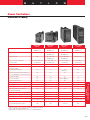
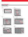
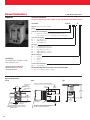
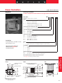
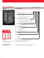
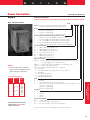
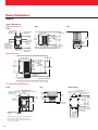
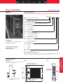
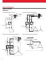
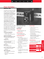
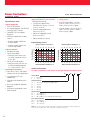
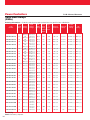
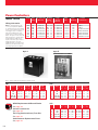
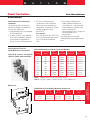
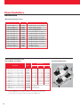
W
A
T
L
O
PEAN
URO
E
H
T
IVE
S WI
PLIE DIRECT ) and
M
O
C
EMC 6 (1997-98
Power Controllers
132
0178
EN 6
EN 5 Request…entative
n
es
DIN-A-MITE® Family
Co
Agency Approvals
• UL®508 listed and C-UL®
• UL®50, UL®1604, and CE
Single Contactor
ac or dc,
Proportional
Voltage or Current
Burst Fired
to 100 Amps
DIN-A-MITE
Current
Monitor
Achieve Optimum Temperature
Control With Variable Time Base
Control
Variable time base control meets the
rapid switching demands of PID
temperature control to deliver more
accurate process control. It also
increases heater life by reducing
temperature over- and undershoot.
Low Electrical Noise
Burst firing switches ac current at
zero cross (zero potential) to
produce minimal RFI and EMI
electric noise (radio frequency
interference/electromagnetic
interference). This low electrical
noise quality helps prevent
Phase-Angle
Fired up to
80 Amps
Alarm
interference with sensor circuits and
particularly sensitive equipment in
your system.
Rugged, Back-to-Back SCR
Design Insures Long Term
Reliability
With solid state components, there's
no limit on the number of switching
cycles the DIN-A-MITE can perform.
The four DIN-A-MITE styles meet
most application requirements by
tolerating harsh industrial
environments, electrical spikes and
dissipating less power. When
properly applied, the DIN-A-MITE
will outlast all other types of nonelectronic power controllers.
DIN-A-MITE®
• No drilling and tapping necessary
• Same footprint as comparably
rated MDRs
o
Repr
lable
Avai r Watlow
u
o
Y
nsult
UL® and C-UL® are registered trademarks of
the Underwriter’s Laboratories, Inc.
161
Power Controllers
Made in the United States of
America, Watlow's DIN-A-MITE®
family of solid state power controllers
provides SCR control, heatsink,
wiring and touch-safe exterior in
one package. By designing the
DIN-A-MITE® as a total power
controller unit, the need to prep
wires for terminals, find the right
heat sink and determine adequate
terminations is eliminated. It's a
complete package you can install
with Control Confidence®.
Performance Capabilities
Four DIN-A-MITE styles meet most
power controller needs with ratings
from 18 to 100 amps with voltages
from 120 to 600VÅ(ac).
Features and Benefits
DIN-rail or sub-panel mounting
• Simple, fast installation
No mercury
• Environmentally safe product
Compact size
• Reduced panel space; less cost
Touch-safe exterior
Increased safety for installer/user
Easy Installation
Installation is simple and fast; saving
time and money. All you have to do
is strip wires and make connections.
• Sub-panel or DIN-rail mounting
W
Power Controllers
DIN-A-MITE Family
Reduce Wear On Thermal System
With optional variable time base
switching, the DIN-A-MITE
automatically adjusts output cycle
time to meet system demands.
The benefits of this option are:
• Heater output equal to load
demand
• Minimized temperature over- and
undershoot
Terminal System Helps Prevent
Wiring Failures
A proven high-current copper
terminal design ensures optimum
electrical connection to reduce heat
build-up. This helps avoid
connection failures and ensures
overall wiring reliability. To further
reduce “hot spots,” we've eliminated
all unnecessary wires and fasteners
which could possibly loosen, heat up
and break down.
Compact Solid State Power
Controller Delivers Big
Performance in a Small Package
Watlow's DIN-A-MITE Style A, B, C
and D power controllers provide a
low-cost, highly compact and
versatile solid state power control.
What's more, no need to worry about
mercury; all DIN-A-MITEs are
mercury free and fit the same
footprint as a comparably rated
MDR. Each feature sub-panel
mounting, while Styles A, B and C
also have DIN-rail mounting
capability.
Style A Capabilities
Style A capabilities include singlephase burst fire switching up to 25
amps at 600VÅ(ac) (see rating curve).
Variable time base, 4-20mAÎ(dc)
process control or VÅ(ac)/ VÎ(dc)
input contactor versions are
available. All configurations are code
number dependent and factory
selectable, 50/60Hz independent.
162
Style B Capabilities
Style B capabilities include 1-phase
and 3-phase burst fire up to 40 and
33 amps, respectively, at 600VÅ(ac)
(see rating curve).
Variable time base, 4-20mAÎ(dc)
process control or VÅ(ac)/VÎ(dc)
input contactor versions are
available. All configurations are code
number dependent and factory
selectable, 50/60Hz independent.
Style C Capabilities
Style C capabilities include 1-phase
and 3-phase, 2-leg, and 3-phase,
3-leg burst fire, as well as 1-phase,
phase-angle fire. Burst fire operation
from 120 to 600VÅ(ac), phase angle
operation from 120 to 600VÅ(ac).
Current switching capabilities range
from 30 to 80 amps depending on
the model ordered (see output rating
curve).
Input options include variable time
base, 4-20mAÎ(dc) process control,
linear voltage control, manual control
or VÅ(ac)/VÎ(dc) contactor input.
All configurations are code number
dependent and factory selectable.
All models are 50/60Hz independent.
Style D Capabilities
Style D capabilities include 1-phase
switching up to 100 amps at
600VÅ(ac) and 30°C (86°F) (see
rating curve). Limited 3-phase
operation is possible by ganging two
and/or three Style D DIN-A-MITE
contactor inputs together.
Style D features on-board
semiconductor fuses (accessible
from the front). Application is further
enhanced with optional current
transformer option for external load
current monitoring and “shorted SCR
detector” on some models.
Variable time base, 4-20mAÎ(dc)
process control or VÅ(ac)/ VÎ(dc)
input contactor options are available.
All configurations are code number
dependent and factory selectable,
50/60Hz independent.
The standard sub-panel mounting
footprint is equal to that of an industry
standard mercury displacement relay.
DIN-A-MITE Style A, B, C and D
Features
• Faster switching with solid state
components. Better control saves
energy and extends heater life.
• Back-to-back SCR design for
increased durability.
• Three-year warranty assures
Control Confidence®.
Style B and C Features
• 1- and 3-phase power permits
use in a variety of applications.
• Shorted output detector
(optional) notifies a shorted SCR
condition.
Style C Features
• Open heater detector (optional)
notifies when a partial or totally
open heater occurs.
Style D Features
• On-board semiconductor fusing
provides quick access with no
extra mounting necessary.
• Optional load current monitor
detects changes in load current.
Applications
• Petroleum/chemical
• Ovens/furnaces
•
•
•
•
Wave solder and reflow
Packaging
Foodservice equipment
Semiconductor processing
Agency Approvals
• UL® 508 Listed, File #E73741
• C-UL® approved
• CE approved with proper line filter
• DIN-A-MITE Style C thru-wall
mount is also UL®50 and UL®1604
approved.
• CE and EN 61326 Industrial
Immunity Class A emissions with
filter. EN 50178 safety directive
W
A
T
L
O
W
Power Controllers
DIN-A-MITE Family
DIN-A-MITE
Style A
DIN-A-MITE
Style B
Up to 25 amps
Up to 40 amps
Up to 80 amps
Up to 100 amps
@ 600VÅ(ac)
@ 600VÅ(ac)
@ 600VÅ(ac)
@ 600VÅ(ac)
3-Phase, 2-leg①
No
Up to 33 amps
Up to 80 amps
Gang 2 units
@ 600VÅ(ac)
@ 600VÅ(ac)
3-Phase, 3-leg①
No
Up to 22 amps
Up to 70 amps
@ 600VÅ(ac)
@ 600VÅ(ac)
24, 120 & 240VÅ(ac)
4.5-32VÎ(dc)
24, 120 & 240VÅ(ac)
4.5-32VÎ(dc)
24, 120 & 240VÅ(ac)
4.5-32VÎ(dc)
24, 120 & 240VÅ(ac)
4.5-32VÎ(dc)
Multizone VÅ(ac) & VÎ(dc) Input
No
Yes
Yes
No
4-20mAÎ(dc) Input - Variable
Time Base Output
Yes
Yes
Yes
Yes
Phase-Angle Fire Output➁
No
No
Manual Control Via Potentiometer Input, or
0-5, 1-5 or 0-10VÎ(dc) Linear Voltage Input
No
No
Shorted SCR Alarm
No
Yes
Open Heater Alarm
No
No
1-Phase①
VÅ(ac) & VÎ(dc) - Burst Fire
Contactor Input
No
Yes
No
Yes
Yes
Yes
With “S” input only
No
No
Yes
No
Yes
Din-Rail Mount
Yes
Yes
Yes
No
Sub-Panel Mount
Yes
Yes
Yes
Yes
Cabinet Thru-Wall Heatsink Mount
UL® 50 and UL® 1604
No
No
Yes
No
Electrically Touch-Safe Package
Yes
Yes
Yes
Yes
Back-to-Back SCR Design
Yes
Yes
Yes
Yes
UL® 508 Listed/C-UL®/CE w/filter
Yes
Yes
Yes➁
Yes
(95 X 45 X 98 mm)
3.7 H X 1.8 W X 3.9 in. D
(95 X 80 X 124 mm)
3.7 H X 3.1 W X 4.9 in. D
(150 X 80 X 146 mm)
6.0 H X 3.1 W➂ X 5.7 in. D
(185 X 65 X 240 mm)
7.25 H X 2.5 W X 9.4 in.D
0.32 (0.71)
0.68 (1.5)
1.18 (2.6)
2.95 (6.5)
N/A
N/A
1.45 (3.2)
N/A
DIN-A-MITE®
No
No
Refer to curves on page 164 for your specific application ratings.
Phase angle fire is not CE approved.
Will fit within the width dimension of most comparable MDRs.
163
Power Controllers
No
No
Controller Weight w/fan: kg (lbs)
c
Gang 3 units
On Board Semiconductor Fusing
Controller Weight: kg (lbs)
b
Yes
1-phase only
DIN-A-MITE
Style D
Load Current Monitor CT
Dimensions
a
DIN-A-MITE
Style C
Power Controllers
DIN-A-MITE Family
Output Current Rating Curves
Style A
DIN-A-MITE Style A Ratings at 100% On
25
20
15
10
5
0
25 30 35 40 45 50 55 60 65 70 75 80 85
Maximum Internal Enclosure Ambient Temperature (°C)
DIN-A-MITE Style B Ratings at 100% On
90
85
Natural Convection
80
75
70
65
ase
ph
gle
Sin
eg
,2l
ase
3-ph
leg
se, 3
3-pha
Current (Amps) into
a Resistive Load
30
Maximum Internal Enclosure Ambient Temperature (°C)
Style B
60
55
50
45
40
35
30
25
0
5 10 15 20 25 30 35 40 45 50 55 60
Current (Amps) into a Resistive Load
DIN-A-MITE Style C Ratings at 100% On
90
85
Natural Convection
80
75
as
ph
e
g
le
g
le
35
30
25
0
5 10 15 20 25 30 35 40 45 50 55 60 65 70 75 80 85 90
Current (Amps) into a Resistive Load
80
Recommended maximum
enclosure temperature is 80˚ C (176˚ F)
75
70
65
as
e,
se
g
le
leg
40
2
,3
45
se
ha
ph
ha
50
ep
3-
3-p
55
l
ng
Si
Thru-Wall Heatsink
60
35
30
25
0
5 10 15 20 25 30 35 40 45 50 55 60 65 70 75 80
Current (Amps) into a Resistive Load
Maximum Internal Enclosure Ambient Temperature ( ˚C )
Style D
DIN-A-MITE Style C Ratings at 100% On
Ambient Air Around Heatsink Fins ( ˚C)
gle
2
40
Current (Amps) into a Resistive Load
Style C—Thru-Wall
164
3
5 10 15 20 25 30 35 40 45 50 55 60 65 70 75 80
e,
0
45
e,
25
as
30
50
as
e
35
55
ph
as
g
2 le
leg
40
ph
se,
e, 3
45
Fan-Cooled
60
ph
le
ng
50
ha
has
3-p
55
65
3-
Si
60
75
70
3-
65
DIN-A-MITE Style C Ratings at 100% On
80
Sin
70
Maximum Internal Enclosure Ambient Temperature (°C)
Style C - Fan Cooled
3-p
Maximum Internal Enclosure Ambient Temperature (°C)
Style C
DIN-A-MITE Style D Natural Convection Ratings at 100% On
85
80
75
70
65
60
55
50
45
40
35
30
25
0
5 10 15 20 25 30 35 40 45 50 55 60 65 70 75 80 85 90 95 100 105
Current (Amps) Into a Resistive Load
W
A
T
L
O
W
Power Controllers
DIN-A-MITE Family
Specifications Common To Styles
A, B, C and D
Control Mode-Burst Fire
• VÅ(ac) input contactor
• VÎ(dc) input contactor
• 4-20mAÎ(dc) variable time base
control
Operator Interface
• Command signal input
• Input signal indication LED
Input
• VÅ(ac): 24, 120, 240 nominal 25mA maximum per controlled leg
Specifications Unique To Each
Style
Multizone Input— Styles B & C
• VÅ(ac) input contactor
• VÎ(dc) input contactor
• Available 2 and 3 leg only
Amperage—Style A
• 1-phase, 24 amp output maximum
at 30°C (86°F) into a resistive loadc
• Maximum surge current for
16.6mSec. 380 amps peak
• Maximum I2t for fusing 4,000
A2 Sec.
Amperage—Style C
• Natural convection and fan
cooled, in 1-phase and 3-phase
models. See output rating curves
on page 164
• Maximum surge current for
16.6mSec. 1350 amps peak
• Maximum I2t for fusing 9100 A2 Sec.
a
b
c
Not available on Style D
Style C phase angle fire is not CE approved
See output current rating curves, page 164.
• 4-20mAÎ(dc) loop powered:
375Ω input impedance
Storage Temperature
• -40 to 85°C (-40 to 185°F)
Output Voltage
• 120-240VÅ(ac) units: 48VÅ(ac)
minimum to 265VÅ(ac) maximum
• 277-600VÅ(ac) units: 85VÅ(ac)
minimum to 660VÅ(ac) maximum
• Off state leakage 1mAÎ(dc) at
25°C (77°F) maximum
Mounting
Options include DIN-raila or
standard sub-panel mounting
Style C—Phase Angle Firing2
• 1-phase operation
• Line voltage compensation
Shorted Output Alarm Option—
Styles B, C & D
• Triac output
• 24 to 240VÅ(ac), 300mA @ 25°C,
125mA @ 80°C (176°F)
• Energizes on alarm
• Holding current 200µA minimum
• Latching current 5mA typical
• Soft start (4 seconds) on power up
• Missing half cycle detection
(engages ESD and restarts soft)
• Optional current limit feature
• Linear voltage/current or manual
control input. 5kΩ input
impedance for voltage and
250 ohms for 4-20mA
• 120, 208, 240, 277, 400, 480, and
600VÅ(ac) operation. Model
number dependent
Style C—Single Cycle Variable
Time Base
• 1-phase and 3-phase operation
• Linearized input to output
• Linear voltage/current or manual
control input. 5kΩ input
impedance for voltage and 250
ohms for 4-20mA
• 120, 208, 240, 277, 400, 480,
and 600VÅ(ac) operation. Model
number dependent
Amperage—Style D
• 1-phase, 100 amp output
maximum at 30°C (86°F)c
• Maximum surge current for
16.6mSec. 1800 amps peak
• Maximum I2t for fusing 20,000
A2 Sec.
• The DIN-rail specification is: DIN
EN 50022, 35 mm x 7.5 mm
Terminals—Styles A & B
• Compression - will accept #8-18
AWG wire (8.4 mm2 - 0.82 mm2)
Terminals—Style C
• Compression - will accept #4-14
AWG wire (21.2 mm2 - 2.1 mm2)
Terminals—Style D
• Compression - will accept #2-6
AWG wire (33.6 mm2 - 13.3 mm2)
Mounting—Style D
• Standard sub-panel mounting; fits
the same mounting pattern as a
100 amp 1-phase MDR
• Mounting holes offer clearance for
#10 screw
• On-board semiconductor fusing,
Bussmann P/N 170N3437
DIN-A-MITE®
• Maximum I2t for fusing 4,000
A2 Sec.
Operating Environment
• Up to 80°C (176°F),c see output
rating curve for specific
application
Current Sensing—Style D
• On-board current transformer,
0.2VÅ(ac) output signal per amp
load current into 1000Ω load
165
Power Controllers
Amperage—Style B
• 1-phase and 3-phase models.
See output rating curves on
page 164
• Maximum surge current for
16.6mSec. 380 amps peak
• VÎ(dc): 4.5 to 32VÎ(dc):
maximum current @ 4.5V is 6mA
per leg. Add 2mA per LED used
to the total current
Power Controllers
F.O.B. Winona, Minnesota
Style A
Ordering Information
To order, complete the code number on the right with the information below.
DA10-____-0___
DIN-A-MITE
Style A = Solid state power controller
Phase
1
=
1-phase, 1 controlled leg
Cooling and Current Rating
0
=
Natural convection current rating 18A @ 50˚C (122˚F)
(See derating curve for current rating at other temperatures)
Line and Load Voltage
02 =
24 to 48VÅ(ac)
24 =
100 to 240VÅ(ac)
60 =
277 to 600VÅ(ac)
Input Type
C0 =
4.5 to 32VÎ(dc) contactor
F0 =
4 to 20mAÎ(dc) proportional
K1 =
22 to 26VÅ(ac) contactor
K2 =
100 to 120VÅ(ac) contactor
K3 =
200 to 240VÅ(ac) contactor
Manual Language
0
=
English
1
=
German
2
=
Spanish
3
=
French
Availability
All combinations available in three
working days or less.
Custom parts Designation
00 =
Standard parts
CE approved product. Must use
CE filter listed on page 190 for
conducted emission.
Recommended Semiconductor Fuses and Fuse Kits
See page 191 for listings and part numbers.
Style A Dimensions
Front
Side
Top
Clearance for Air Flow and Bending Radius
34 mm
(1.34 in.)
Allowance for
Fastener
Metric = M4
26 mm
(1.03 in.)
102 mm
(4.00 in.)
Grounding Ha
(#6)
98 mm
(3.87 in.)
40 mm
(1.56 in.)
49 mm
(1.92 in.)
11 mm
(0.44 in.)
Allowance for #8
Fastener
DIN-EN 50022 35 mm by 7.5 mm Rail
Clipping Distance 34.7 mm (1.37 in.) to
35.3 mm (1.39 in.)
166
71 mm 94 mm
(2.80 in.) (3.69 in.)
8
(3.
41 mm
(1.60 in.)
Rail Release Tab
(Pull Down)
Clearance for Air Flow and Bending Radius
Zero Electrical Clearance Required
50 mm
(1.97 in.)
102 mm
(4.00 in.)
W
A
T
L
O
W
Power Controllers
Style B
F.O.B.: Winona, Minnesota
Ordering Information
To order, complete the code number on the right with the information below.
DB__-____-____
DIN-A-MITE
Style B = Solid state power controller
Phase
1
=
2
=
3
=
8
=
9
=
1-phase, 1 controlled leg
3-phase, 2 controlled legs
3-phase, 3 controlled legs
2 independent zones (Input Type C or K)
3 independent zones (Input Type C or K)
Cooling and Current Rating Per Pole
0
=
Natural convection standard DIN-rail or panel mount heatsink
Line and Load Voltage
02 =
24 to 48VÅ(ac)
24 =
120 to 240VÅ(ac)
60 =
277 to 600VÅ(ac)
Availability
All combinations available in three
working days or less.
CE approved product. Must use
CE filter listed on page 190 for
conducted emission.
Input Control Signal
C0 =
4.5 to 32VÎ(dc) contactor
F0 =
4 to 20mAÎ(dc) proportional
K1 =
22 to 26VÅ(ac) contactor
K2 =
100 to 120VÅ(ac) contactor
K3 =
200 to 240VÅ(ac) contactor
Alarm
0
=
S
=
No alarm
Shorted SCR alarm (not available with options 8, and 9 above)
User Manual
0
=
English
1
=
German
2
=
Spanish
3
=
French
Custom Part Numbers
00 =
Standard part
XX =
Any letter or number, custom options, labeling, etc.
Recommended Semiconductor Fuses and Fuse Kits
See page 191 for listings and part numbers.
54 mm
(2.11 in.)
46 mm
(1.81 in.)
38 mm
(1.51 in.)
Allowance for #8 Fastener,
Metric = M4
Top
102 mm (4.00 in.) Clearance for Air Flow
and Wire Bending Radius
26 mm
(1.03 in.)
Grounding Screw (#6)
DIN-A-MITE®
Side
Front
102 mm
(4.00 in.)
124 mm
(4.88 in.)
40 mm
(1.56 in.)
94 mm
(3.69 in) 75 mm
(2.97 in.)
71 mm
(2.80 in.)
83 mm
(3.25 in.)
49 mm
(1.92 in.)
49 mm
(1.91 in.)
Allowance for #8 Fastener,
Metric = M4
Rail Release Tab
41 mm
(Pull Down)
(1.60 in.)
102 mm (4.00 in.) Clearance for Air Flow
and Wire Bending Radius
102 mm
(4.00 in.)
83 mm
(3.25 in.)
Zero Electrical Clearance Required
DIN-EN 50022 35 mm by 7.5 mm Rail
Clipping distance 34.7 mm (1.366 in.)
to 35.3 mm (1.390 in.)
167
Power Controllers
Style B Dimensions
Power Controllers
F.O.B. Winona, Minnesota
Ordering Information
Style C
To order, complete the code number on the right with the information below:
DC__-____-____
Style C = Zero cross solid state power controller in natural and
forced air cooled versions
Phase
1
= 1-phase, 1 controlled leg
2
= 3-phase, 2 controlled legs
3
= 3-phase, 3 controlled legs (use with four wire wye)
8
= 2 independent zones (Input Type C, K)
9
= 3 independent zones (Input Type C, K)
Cooling and Current rating Per Leg (see table on left)
0
= Natural convection standard Din-rail or panel heatsink
1
= Fan cooled 120VÅ(ac) standard Din-rail or panel heatsink
2
= Fan cooled 240VÅ(ac) standard Din-rail or panel heatsink
3
= Fan cooled 24VÎ(dc) standard Din-rail or panel heatsink
T
= Natural convection through wall or cabinet heatsink (NEMA 4X)
Line and Load Voltage
02
= 24 to 48VÅ(ac) (Control C, F, K)
24
= 100 to 240VÅ(ac) (Control C, F, K)
60
= 277 to 600VÅ(ac) (Control C, F, K)
Input Control Signal
Current Rating Table
Phase
Cooling
1
1
1
2, 8
2, 8
2, 8
3, 9
3, 9
3, 9
0
T
(1,2,3)
0
T
(1,2,3)
0
T
(1,2,3)
Current
at 50˚C
(122˚F)
55A
60A
75A
40A
45A
65A
30A
35A
55A
Availability
All combinations available in three
working days or less.
CE approved product. Must use
CE filter listed on page 190 for
conducted emission.
168
C0 =
F0
=
K1 =
K2 =
K3 =
Alarm
4.5 to 32VÎ(dc) contactor
4 to 20mAÎ(dc) proportional
22 to 26VÅ(ac) contactor
100 to 120VÅ(ac) contactor
200 to 240VÅ(ac) contactor
0
= No alarm
S
= Shorted SCR alarm (not available with options 8, and 9 above)
Language
0
= English
1
= German
2
= Spanish
3
= French
Custom Part Numbers
00
= Standard part
XX = Any letter or number, custom options, labeling, etc.
Recommended Semiconductor Fuses and Fuse Kits
See pages 191 for listings and part numbers.
Note: Allow one fuse and one holder per leg fused. Example, a 3-phase,
2-leg DIN-A-MITE requires two fuses and two holders.
W
A
T
L
O
W
Power Controllers
Style C
F.O.B.: Winona, Minnesota
Ordering Information
To order, complete the code number on the right with the information below:
Style C Enhancements
D C _ _- _ _ _ _ - _ _ _ _
Style C = Zero cross and phase-angle fired solid state power
controller in natural and forced air cooled versions.
Phase
1
= 1-phase, 1 controlled leg
2
= 3-phase, 2 controlled legs
3
= 3-phase, 3 controlled legs (use with four wire wye)
Cooling and Current Rating Per Leg (see table on left)
0
= Natural convection standard Din-rail or panel heatsink
1
= Fan cooled 120VÅ(ac) standard Din-rail or panel heatsink
2
= Fan cooled 240VÅ(ac) standard Din-rail or panel heatsink
3
= Fan cooled 24VÎ(dc) standard Din-rail or panel heatsink
T
= Natural convection through wall or cabinet heatsink (NEMA 4X)
Line and Load Voltage
12
= 100 to 120VÅ(ac) (Control L, P, S)
20
= 200 to 208VÅ(ac) (Control L, P, S)
24
= 230 to 240VÅ(ac) (Control L, P, S)
27
= 277VÅ(ac) (Control L, P, S)
40
= 400VÅ(ac) (Control L, P, S)
48
= 480VÅ(ac) (Control L, P, S)
60
= 600VÅ(ac) (Control L, P, S)
Input Control Signal
= Phase-angle with current limiting1 (DC1 only, Alarm 0 only, includes
one current transformer - Single-phase only)
P (0 to 5) = Phase-angle1 (DC1 only, Alarm 0 only - Single-phase only)
S (0 to 5) = Single cycle variable time base
(Select one of the following input options for L, P, S (0 to 5))
0 = 4 to 20mA
1 = 12 to 20mA (single cycle variable time base only - option ‘S’)
2 = 0 to 20mA
3 = 0 to 5VÎ(dc) proportional
4 = 1 to 5VÎ(dc) proportional
5 = 0 to 10VÎ(dc) proportional
Alarm
L (0 to 5)
Option
• Manual Control Kit for process
input cards (1kΩ potentiometer)
order #08-5362 separately.
Current Rating Table
Phase
55A
60A
75A
40A
45A
65A
30A
35A
55A
CE approved product. Must use
CE filter listed on page 190 for
conducted emission.
0
S
H
=
=
=
No alarm
Shorted SCR alarm (for zero cross models only)
Open-heater and shorted-SCR alarm (for input control signal options S only)
1-phase, 1 controlled leg
3-phase, 2 controlled legs
3-phase, 3 controlled legs
Language
0
= English
1
= German
2
= Spanish
3
= French
Custom Part Numbers
00
10
XX
1
=
=
=
DIN-A-MITE®
0
T
(1,2,3)
0
T
(1,2,3)
0
T
(1,2,3)
Current
at 50˚C
(122˚F)
Standard part
1-second soft start (Control option P, L)
Any letter or number, custom options, labeling, etc.
Phase angle models are not CE approved for conducted emissions.
169
Power Controllers
1
1
1
2
2
2
3
3
3
Cooling
Power Controllers
Style C
Style C Dimensions
Without Cooling Fan
Side
Top
Front
38 mm (1.51 in.)
46 mm (1.81 in.)
54 mm (2.11 in.)
Allowance for M4
(#8 Fastener)
1
2
102 mm (4.0 in.) clearance for air flow and wire bending radius
146 mm (5.74 in.)
102 mm (4.0 in.)
142 mm (5.59 in.)
44 mm
57 mm
(1.73 in.)
(2.26 in.)
150 mm
(5.89 in.) 127 mm
(5.00 in.)
79 mm
(3.10 in.)
3
131 mm
(5.17 in.)
138 mm
(5.45 in.)
87 mm
(3.42 in.)
DIN-EN 50022
35 by 7.5 mm rail
(clipping distance =
34.7 to 35.3 mm
[1.366 to 1.390 in.])
4
5
146 mm
(5.74 in.)
Ground
Wire
Entry
Rail Release Tab
(pull down)
102 mm (4.0 in.) minimum
102 mm (4.0 in.) clearance for air flow and wire bending radius
6
83 mm
(3.25 in.)
Front panel is touch-safe, no clearance is required
48 mm
(1.89 in.)
Allowance for M4
(#8 Fastener)
With Cooling Fan
102 mm (4.0 in.) clearance for air flow and wire bending radius
146 mm (5.74 in.)
102 mm (4.0 in.)
142 mm (5.59 in.)
44 mm
57 mm
(1.73 in.)
(2.26 in.)
150 mm
(5.89 in.)
131 mm
(5.17 in.)
79 mm
(3.10 in.)
127 mm 182 mm
(5.00 in.) (7.16 in.)
Rail Release Tab
(pull down)
Front panel is touch-safe,
no clearance is required.
102 mm (4.0 in.) minimum
102 mm (4.0 in.) clearance for air flow and wire bending radius
Thru-Wall DIN-A-MITE Style Ca
Front
Top
102 mm (4.0 in.) minimum
clearance for air flow
(top and bottom)
Panel
Opening
Outline
M5 (0.8 by 10 mm) (8)
M5 Internal Tooth Lock Washer (8)
included
122 mm (4.81 in.)
1
2
Ground lug
(2-8 gauge)
3
178 mm (7.00 in.)
4
5
170
Drill 5.8 mm (0.228 in.) (8)
57 mm (2.25 in.)
outside
(any gauge)
Typical Panel
Opening
Heatsink Outline
9.5 mm (0.375 in.) Reference
10.8 mm (0.425 in.)
114 mm
(4.50 in.)
41.3 mm
(1.625 in.)
55 mm (2.17 in.)
inside
(12 gauge)
Sheet Metal (12 GA)
161.9 mm
(6.375 in.)
117.5 mm
(4.625 in.)
Front panel is touch-safe,
no clearance is required
148.6 mm
(5.850 in.)
6
10 mm (0.4 in.) minimum
clearance for air flow
(both sides)
a
Panel Cutout
With the potential for high thru-wall heatsink
temperatures, application may require a
touch-safe shield. See amperage curves on
page 164 for details.
8.6 mm (0.338 in.) Reference
7.0 mm (0.275 in.)
26.3 mm (1.034 in.)
78.8 mm
(3.103 in.)
98.1 mm
(3.862 in.)
105.1 mm
(4.137 in.)
W
A
T
L
O
W
Power Controllers
F.O.B.: Winona, Minnesota
Style D
Ordering Information
To order, complete the code number on the right with the information below:
DD10 -____-____
Style D = Solid state power controller
Phase
1
=
1-phase, 1 controlled leg
Cooling and Current Rating
0
=
Natural convection current rating 80A @ 50˚C (122˚F)
Line and Load Voltage
02 =
24 to 48VÅ(ac)
24 =
100 to 240VÅ(ac)
48 =
277 to 480VÅ(ac)
60 =
277 to 600VÅ(ac)
Input Control Signal
C0 =
4.5 to 32VÎ(dc) contactor
F0 =
4 to 20mAÎ(dc) proportional
K1 =
22 to 26VÅ(ac) contactor
K2 =
100 to 120VÅ(ac) contactor
K3 =
200 to 240VÅ(ac) contactor
Current Sensing or Alarm
Availability
All combinations available in three
working days or less.
0
=
No alarm
1
=
Load current transformer
S
=
Shorted SCR alarm
User Manual Language
CE approved product. Must use
CE filter listed on page 190 for
conducted emission.
0
=
English
1
=
German
2
=
Spanish
3
=
French
Custom Options
00 =
Standard parts
Recommended Semiconductor Fuses
Bussmann part number 170N3437 65 amp® 660VÅ(ac), Watlow part number 0808-0096-0000
requires two fuses per Style “D” DIN-A-MITE. These should be replaced in pairs.
Top
Side
67 mm
(2.63 in.)
185 mm
(7.28 in.)
61 mm
(2.38 in.)
13 mm (0.5 in.) Clearance
For Air Flow
13 mm
(0.50 in.)
67 mm
(2.63 in.)
(64 mm)
(250 in.)
203 mm (8.0 in.) Clearance For Air
Flow and Bending Radius
54 mm
(2.13 in.)
DIN-A-MITE®
Same mounting footprint as industry standard
mercury displacement relays.
203 mm
(8.0 in.)
Grounding Screw
9.5 mm (.375 in.) 406 mm (16 in.)
(239 mm)
(9.41 in.)
178 mm
(7.0 in.)
13 mm
(0.50 in.)
Allowance For #10 Fastener
Metric = M5
203 mm (8.0 in.) Clearance For Air
Flow and Bending Radius
203 mm
(8.0 in.)
(66 mm)
(2.58 in.)
171
Power Controllers
Style D Dimensions
Footprint
Power Controllers
System Diagram
Examples
1-Phase Output, Styles A, B and C
Semiconductor Fuses
2
1
1
3-Phase, 2-Leg Output, Styles B and C
240VÅ(ac)
and above
Semiconductor Fuses
120VÅ(ac)
and 277VÅ(ac)
L1
L1
L1
L2
L2
Neutral
L3
Limit Control
Contacts
(If Required)
3
1
2
Limit Control
Contacts
(If Required)
3
2
1 2
Input Signal
Input Signal
4
5
6
T3
4
5
6
T2
3-Phase, 3-Leg, 4-Wire Output, Styles B and C
3-Phase, 2-Leg Output, with Two Style D’s
Semiconductor Fuses
L1
L1
1
L2
L3
1
2
3
Limit Control
Contacts
(If Required)
VÅ(ac) or VÎ(dc)
Contactor Input Signal
only - not 4-20mA
DIN-A-MITE
D #1
1
2
2
N
1
L2
DIN-A-MITE
D #2
1
2
1 2
2
Input Signal
L3
4
172
5
6
T1
W
A
T
L
O
W
Power Controllers
SERIES CZR
The SERIES CZR solid state contactor
provides a low-cost, highly compact
and versatile solid state option for
controlling electric heat. With din-rail
and back panel mounting standard on
every controller, the CZR allows for
simple and quick installation.
The extensive capabilities of the
SERIES CZR include single-phase,
18 to 50 amp zero-cross and random
switching up to 600VÅ(ac) (see
output rating curve). The unique
integrated design removes the
guesswork associated with selecting
a proper heat sink and precise
terminations for the application.
SERIES CZR contactors are available
in Vı(ac/dc) input contactor versions.
All configurations are model number
dependent and factory selectable.
The SERIES CZR is reliably backed
by a two-year warranty from Watlow
Winona.
Performance Capabilities
• Output 18 to 50 amps
• Output voltage up to 660VÅ(ac)
Features and Benefits
DIN-rail or standard panel mount
• Versatile, quick and low-cost
installation
Compact size
• Reduces panel space; less cost
Mercury-free
• Environmentally safe
Faster switching with solid state
• Saves energy and extends
heater life
Agency Approvals
• UL® recognized, CSA certified,
VDE and CE
• Applications requiring agency
approval
• Rugged design
• 24 volt; 24VÅ(ac) min. to
280VÅ(ac) max.
Specifications
Control Mode
• Zero-cross or random fired
contactor output
Operator Interface
• Command signal input
• Input signal indication LED
Input Command Signal
• Input Type DC1
• Turn on voltage 4VÎ(dc) max.,
turn off voltage 1VÎ(dc) min.
• Input current: dc typically 10mA
@ 4VÎ(dc),13mA @ 32VÎ(dc)
• Input Type AC1
• 90 to 140Vrms, must turn on at
90VÅ(ac), must turn off at
10VÅ(ac)
• Input current: 15mA typical
@120VÅ(ac)
• Input Type AC2
• 18 to 36VÅ(ac) input, must turn
on at 18VÅ(ac), must turn off at
10VÅ(ac)
• 480 volt; 48VÅ(ac) min. to
530VÅ(ac) max.
• 600 volt; 48VÅ(ac) min. to
660VÅ(ac) max. (not available on
18 amp version)
• Off state leakage
1mA at 25°C (77°F) max. for
600VÅ(ac) models; 10mA at 25°C
(77°F) max. for 24 through
480VÅ(ac) models
• Holding current: 250mA max.
Output Amperage
• See output rating curve. Ratings
are into a resistive heater load
Output Amperage Rating
Model
18
24
34
Maximum Surge Current
16.6 mSec
625
250
625
Maximum I2t for fusing 1,620 260 1,620
42
50
Maximum Surge Current
16.6 mSec
1,000
1,000
Maximum I2t for fusing
4,150
6,000
Model
SERIES CZR
• Increase safety for installer and
operator
Output Voltage
• Input current: 10mA typical @
24VÅ(ac)
173
Power Controllers
Touch-safe terminals
Back-to-back SCR design
Power Controllers
F.O.B.: Winona, Minnesota
SERIES CZR
Mounting
Weight/Dimensions
Options include DIN-rail or standard
back panel mounting.
• 260 g (9.2 oz)
Specifications Cont.
• Class II construction
• UL® 508 recognition, File #E73741
and CSA File LR 700195
• 73/23/EEC CE Low Voltage
Directive
• VDE 0805, registration number
126921
• License number 136037 for
18 amp models
• The DIN-rail specification:
DIN EN 50022, 35 mm x 7.5 mm
(1.37 in. x 0.30 in.)
• Minimum clipping distance:
34.8 mm (1.37 in.)
• Mount cooling fins vertical
Output Rating Curves
Maximum Ambient Temperature °F
• For 18 amp models:
• Maximum wire size 3.0 mm
(10 AWG), torque to 0.6 Nm
(5.3 in. lbs)
50
Operating Environment
86
104 122 140 158 176
50
34 A
40
24 A
30
18 A
20
10
0
75
• Insulation only tested to 3,000
meters
• Units are suitable for “pollution
degree 2”
• Cycle time should be less than
three seconds
86
104 122 140 158 176
50 A
60
45
42 A
30
15
0
10
20
30
40
50
60
70
80
Maximum Ambient Temperature °C
10
20
30
40
50
60
70
80
Maximum Ambient Temperature °C
Ordering Information
To order, complete the code number to the right with the information below:
• Up to 80°C (176°F). See output
rating curves for your application.
• 0 to 90 percent RH, noncondensing
68
90
50
• For 24 to 50 amp models:
• Maximum wire size 16.0 mm
(6 AWG stranded) torque to
1.5-1.7 Nm (13-15 in. lbs)
68
Maximum Ambient Temperature °F
60
Current (Amps)
• Compression type
• 18 amp models: 100 mm (3.95 in.)
high x 22.6 mm (0.89 in.) wide x
99 mm (3.9 in.) deep
• Maximum clipping distance:
35.3 mm (1.39 in.)
• License number 130515 for
24 to 50 amp models
Output Terminals
• 24 to 50 amp models: 100 mm
(3.95 in.) high x 45 mm (1.75 in.)
wide x 109 mm (4.3 in.) deep
Current (Amps)
Agency Approvals
C___-A__V-___0
Control Mode
R
=
Random
Z
=
Zero-cross
Output Amperage
18 =
18 amp (not available with 600V output)
24 =
24 amp
34 =
34 amp
42 =
42 amp
50 =
50 amp
Output Voltage
24 =
24 to 280VÅ(ac)
48 =
48 to 530VÅ(ac)
60 =
60 to 660VÅ(ac) (not available with 18A model)
Input Type (Contactor)
DC1 =
AC1 =
AC2 =
4 to 32VÎ(dc)
90 to 140VÅ(ac)
18 to 36VÅ(ac)
Note: Do not use the AC1 and AC2 input type models with temperature control outputs that
include an AC snubber filter. This could cause the CZR to stay full on.
174
W
A
T
L
O
W
Power Controllers
POWER SERIES
Watlow has manufactured solid state
power controllers for over 30 years.
Watlow’s POWER SERIES represents
the latest in SCR power controller
technology. This microprocessorbased product offers features and
application flexibility unmatched by
any other SCR power controller on
the market today.
Capabilities of Watlow’s POWER
SERIES controllers include singlephase and three-phase models from
65 to 250 amps. Field configurable
phase-angle or zero cross firing
improves application flexibility on site
where you need it. The 50/60Hz
independent operation allows
utilization almost everywhere in the
world without special calibration
considerations. Serial communication
utilizing Modbus™ protocol provides
remote control setup and monitoring
of load status from a nearby
computer station or control room.
On-board semiconductor fusing
improves reliability by protecting the
SCRs from heater short circuits. Plus,
on-board heater bakeout and control
diagnostics can help eliminate initial
start up problems. All these benefits
are in a touch-safe package that can
be quickly and easily mounted in
your control cabinet.
• 65 to 250 amps
• Up to 660VÅ(ac)
Power Bases
• Extremely versatile, field
configurable
• Single-phase, (2 SCRs)
Snap-fit on a pre-mounted plate
• Easy installation
Models 65 through 250 amp
ratings
• Handles a wide range of loads
Adjustable soft start
• Provides application flexibility
Heater and control diagnostics
capabilities
• Monitor actual heater and control
performance
• 3-phase, 2-leg control, (4 SCRs),
resistive load only, zero cross
firing only
• 3-phase, 3-leg control, (6 SCRs)
• 3-phase, 3-leg control, (6 SCRs)
for 4-wire wye loads
• Multizone, two and three singlephase zones
Output Control Options
• Zero cross control, fixed time
base
Electrically touch-safe package
• Time base one or four seconds
with digital programmer
• Increased safety for installer and
users
• Zero cross control, variable time
base
Serial communications with
Modbus™ RTU protocol
• Phase-angle control and phaseangle control with current limit
(not for 3-phase, 2-leg models)
• Computer control and/or
monitoring
Multizone capability
• Increased application flexibility,
reduced panel space
POWER SERIES
Performance Capabilities
Specifications
Microprocessor-based technology
• Soft start factory default four
seconds upon power-up, and
adjustable from 0.0 to 120
seconds
Modbus™ is a registered trademark of Schneider
Automation, Inc.
175
Power Controllers
Watlow’s POWER SERIES controllers
are UL® listed and C-UL®, so users
can be assured that the controllers
meet world safety and operational
standards.
Features and Benefits
Power Controllers
POWER SERIES
Heater Bakeout
Specifications Cont.
• For single-phase (phase to
neutral) and 3-phase 6 SCR
models only (not for 3-phase,
2-leg models)
• Soft start upon input signal
change, output rate of change
adjustable to limit max rate of
change from 0.1 to 100 percent
per 0.1 second. Factory default
10 percent
• Current transformer included
when required
• Line voltage compensated
(variable time base and
phase angle controllers only)
• Adjustable 0 - 9999 minutes with
over current trip
• Internal current transformer
included
• Standby or non-operational mode
Command Signal Input
Output Voltage and Current Rating
Analog
• 24 to 120VÅ(ac) (+10 percent,
-15 percent)
• Field selectable linear voltage
and current of low and high
points within 0-20mA and
0-10VÎ(dc)
• 200 to 480VÅ(ac) (+10 percent,
-15 percent)
• 200 to 600VÅ(ac) (+10 percent,
-15 percent)
• 65 through 250 amps per pole,
model dependent; see Output
Amperage Chart page 178
• Minimum load 1 amp rms ac
• Maximum leakage current 5mA
Alarms
• Manual control input through front
panel as a percent power
• Factory default 4-20mA input
• Voltage input impedance 11kΩ
nominal
• Current input impedance 100Ω
nominal
Digital
• Latching or non-latching
• On-board digital programmer/
display and optional serial
communications
• Separate high and low values
Retransmit
• Alarm silencing (inhibit) on power
up for alarm
• Field selectable and scalable
within 0-20mA, 800Ω maximum or
0-10VÎ(dc), load, 1KΩ minimum
load. The default is 4-20mA
• Single alarm relay
• Alarm indication LEDs, shorted
SCR, open heater
• Electromechanical relay, form C
contact, software configurable
• Minimum load current 10mA @
5VÎ(dc)
• Rated resistive loads: 3 amps @
250VÅ(ac) or 30VÎ(dc) max.,
inductive load rating 1.5 amps
with a power factor ≥ 0.4 without
contact suppression
176
• Soft start with over current trip,
runs until programmed bakeout
time expires, then goes burst or
phase-angle firing. Factory
default of 24 hours
• Resolution:
mA ranges = ±5µA nominal
VÎ(dc) = ranges 2.5mV nominal
• Calibration accuracy:
mA ranges = ±20µA
VÎ(dc) ranges = 10mV nominal
• Temperature stability: 100ppm°C
Digital Programmer/Display and
Communications Capabilities
• Programming functions
• Adjust input and output control
type, alarms and soft start, heater
bakeout and current limit prompts
• Monitoring functions
• Display input and output values
along with actual output current
• Data retention of digital
programmer/display upon power
failure via nonvolatile memory
Serial Communications
• RS-232 for single drop control
• EIA-485 for single or multidrop
control
• 32 units maximum can be
connected. With additional 485
repeater hardware, up to 247
units may be connected
• Isolated
• Modbus™ RTU protocol
• 1200, 2400, 4800, 9600,19200
baud rates
Controller Power Supply
• Universal line voltage input range
100 to 240VÅ(ac) (+10 percent,
-15 percent) at 55VA max
• 50/60Hz ± 5 percent line
frequency independent
• Controller line voltage for
electronic power supply can be
run on separate line voltage
Natural Convection and Fan
Cooled Models
• Cabinet venting may be required
• See chart on page 178 for models
that include fan cooling
Power Dissipation (Watts)
• Approximately 1.25 watts/amp
per controlled leg
W
A
T
L
O
W
Power Controllers
POWER SERIES
Agency Approvals
•
UL®
Specifications Cont.
508 listed, File #E73741,
Vol. three, Sec. two
Isolation
•
C-UL®
• Command signal to load and
line/load to ground 2200VÅ(ac)
minimum
• VDE EN 50178 License 115054
• On-board semiconductor fuses
provide SCR protection
Mounting
• Mounts on a removable subplate
• Heat sink fins must be mounted in
vertical orientation
High Current Terminals
• Touch safe
• 10 mm (0.375 in.) Allen head
compression terminals will accept
#6 AWG to 350 MCM wire. Allen
wrench adapter (included)
for 10 mm (0.375 in.) socket,
6 point only
• Torque to 180 in.-lbs (20.3 Nm)
• Wire strip to 30 mm (1.125 in.)
Controller Terminals
• Touch safe
• 2.5 mm (0.125 in.) blade screwdriver, accepts 12-22 AWG or
2 No. 22-18 AWG wires
• Torque to 8 in.-lbs (0.9 Nm)
• Wire strip to 6 mm (0.24 in.)
Operating Environment
• 50°C (122°F) base rating
• 0 to 90 percent RH,
non-condensing
• Meets EN50178, pollution degree
three
Storage Temperature
• -40 to 85°C (-40 to 185°F)
Shipping Weight
• 10.3 kg (23 lbs)
Single-Phase Configuration
Heater Diagnostics
This configuration can be purchased
with any or all the features available
on the POWER SERIES, based on
customer preference. It is intended
for resistive heaters, but can also be
used on transformer connected
loads in the phase-angle firing mode.
Heater diagnostics may include
some or all of the features that
require heater current monitoring,
depending on the model selected.
Heater current monitoring is only
available with heater diagnostics
installed on the controller. The
features dependent on heater current
monitoring are heater bakeout,
current limiting, heater kVA
monitoring, retransmit and heater
monitoring alarms such as open
heater, heater out of tolerance, load
balance and shorted SCR
detection/error. Heater diagnostics
must also be installed if you need
phase-angle control with current limit.
listed to C22.2 NO. 14
Three-Phase, Two-Leg
Configuration
This configuration is intended for
zero cross firing only into a stable
resistive heater. Typically, a threephase delta or ungrounded wye
connected heater is used and only
two of the three VÅ line phases are
switched. The third-phase is a direct
connection through a bussbar on
board the POWER SERIES. Heater
current monitoring and kVA options
are available via the heater
diagnostics option.
Three-Phase, Three Leg
Configuration
All POWER SERIES options are
available with this configuration.
It works well with phase-angle firing
into a three-phase, three-wire wye
or delta connected heater. In this
configuration, the more common
applications are transformer
connected loads with heaters
requiring a soft start and/or
current limiting.
POWER SERIES
• 0 to 65°C (32 to 149°F) natural
convection cooled
• CE 89/336/EEC (EN61326), Class
A with filter,
CE 73/23/EEC (EN50178)
This configuration is available in two
and three single-phase zones and all
the features of a single-phase unit
are available. (Note that there is only
one alarm relay and all zones in the
controller must use the same control
method.)
The three-phase, four-wire
configuration is intended for zero
cross firing into a three-phase
grounded wye/star heater (This is a
separate hardware option, model
number dependent.)
177
Power Controllers
• 0 to 60°C (32 to 140°F) fan cooled
Single-Phase, Multizone
Configuration
Power Controllers
POWER SERIES
F.O.B.: Winona, Minnesota
Ordering Information
To order, complete the code number on the right with the information below.
PC__ -____-____
Front View
POWER SERIES = Microprocessor-based, solid state
power controller
1
2
3
Package Style
C
=
Phase
POWER SERIES
Solid State Power Controller
354 mm
(14.0 in.)
1
=
1-phase
2
=
3-phase/2-leg control, (4 SCRs)
3
=
3-phase/3-leg control, (6 SCRs)
4
=
3-phase/4-wire, wye connected load
8
=
2 single-phase zones
9
=
3 single-phase zones
Heater Diagnostics
0
1
4
5
65 to 250 amps
None
Heater diagnostics (required for any heater current
monitoring or current limiting).
Output Amperage Rating
(See amperage chart below.)
Output Voltage Rating
6
Top View
=
=
A
=
24 to 120V
B
=
200 to 480V
C
=
200 to 600V
Communications
200 mm
(7.9 in.)
0
=
None
1
=
EIA/TIA-232/485 communications, opto-isolated (field selectable)
Feedback/Retransmit
0
1
=
=
None
Load current feedback (0 - 10V or 0 - 20mA scalable retransmit output)
Must have heater diagnostics selected)
Custom
191 mm
(7.5 in.)
00 =
AA =
XX =
Mounting Plate Dimensions
None
No watlow logo with agency approval marks
Custom, consult factory for options
Note: See replacement semiconductor fuses on page 190.
Amperage Chart—50˚C (122˚F)
Mounting Holes (4)
7 mm
(0.27 in.)
Non-Fan Cooled
Release Tab
Key Slots
178 mm
(7.00 in.)
102 mm
(4.00 in.)
151 mm
(5.93 in.)
178
39 mm
25 mm (1.53 in.)
(0.97 in.)
Single Phase
Code Amperage
N20
100A
N25
140A
N30
165A
2-Zone and
3-Phase, 2-Leg
Code Amperage
N20
80A
N25
105A
N30
120A
3-Zone and
3-Phase, 3-Leg
Code Amperage
N20
65A
N25
85A
N30
105A
Fan Cooled
Single Phase
Code Amperage
3-Phase, 2-Leg
Code Amperage
3-Phase, 3-Leg
Code Amperage
F20
F25
F30
125A
200A
250A
F20
F25
F30
120A
160A
185A
F20
F25
F30
90A
140A
155A
W
A
T
L
O
W
Power Controllers
E-SAFE® RELAY
The E-SAFE® mercury-free relay
from Watlow provides reliable and
accurate power switching for
processing applications.
This relay can exceed the
performance of typical mercury
relays while fitting within the same
footprint. The E-SAFE RELAY bridges
the gap between mercury
displacement relays (MDRs) and
solid state relays (SSRs) by providing
superior power switching in a
non-mercury solution at a lower cost.
This mercury-free relay also provides
longer contact life and higher
performance than typical mechanical
relays used in equipment.
The E-SAFE RELAY eliminates
mercury, reduces arcing and
electrical noise and provides
processors with an excellent solution
for equipment power switching. The
absence of mercury in the E-SAFE
RELAY reduces toxic metal hazards
in processing environments.
Performance Capabilities
• Up to 40 amps
• 240 VÅ(ac)
Features and Benefits
High current transient suppression
Specifications
Output Rating
• Output rating: from 20A to 40A
maximum resistive load at
-30 to 55°C (-22 to 130°F)
• 20A to 40A max. per pole into a
resistive load
• Maximum power switching
voltage: 208/240VÅ(ac),
three pole
• Coil voltage: 24VÅ(ac),
120VÅ(ac) and 220VÅ(ac)
• Maximum operating ambient
temperature: 55°C (130°F)
Control Mode
• Low electrical noise
• Zero cross switching output
• Out performs mechanical
contactors
• Form A outputs, without arcing
Compact size
• Fits footprint of definite purpose
relays and most 30 to 50 amp
mercury relays
• Easily retrofittable
Environmentally safer than
mercury contactors
• Eliminates toxic waste (mercury)
from the application environment
and disposal from failed mercury
contactors
• Cycle rate: 30 cycles per minute,
maximum
Input Command Signal
• 24VÅ(ac) (+10 / -15 percent),
120VÅ(ac) (+10 / -10 percent)
220VÅ(ac) (+10 / -15 percent)
• 50/60Hz, less than 9VA
Operating Life
• 1,000,000 switching cycles at
max. rating
Weight/Dimensions
• Weight: 0.560 kg (1.25 lbs.)
• 96.0 mm (3.78 in.) high x
82.3 mm (3.24 in.) wide x
90.2 mm (3.55 in.) deep
Terminals
• Controller input: Compression,
accept #22 to 10
(0.2 to 6 mm2) AWG wire. Torque
to 7 in.-lbs (0.8 Nm) max.
• Output: Compression, accept #14
to 6 (2.5 to 16 mm2) AWG wire.
Torque to 35 in.-lbs max.
(3.95 Nm)
E-SAFE® RELAY
• Extended contact life
• Three pole
Note: Do not place an R/C snubber
(filter) on the E-SAFE RELAY
input command signal. Do not
place on temperature control
output.
Agency approvals
• UL® 508 listed and C-UL®
179
Power Controllers
• High reliability
• Maximum cycle rate: 30 cycles
per minute
• 208/240VÅ(ac), 50/60Hz, each
pole
Power Controllers
F.O.B.: Winona, Minnesota
Ordering Information
E-SAFE RELAY
To order, complete the code number on the right with the information below.
Specifications Cont.
ES__ -____-____
Operating Environment
• Operating temperature up to
-30 to 55°C (-22 to 130°F)
E-SAFE RELAY = Hybrid zero cross contactor
• 5 to 85 percent RH,
non-condensing
20 =
20 amp
40 =
30 amp
Number of Poles
• Shipping and storage
temperature -40 to 85°C
(-40 to 185°F)
3
=
Three pole
Control Voltage
Amperage
024-AC = 24VÅ(ac)
120-AC = 120VÅ(ac)
220-AC = 220VÅ(ac)
Label Options
Mounting
• Definite purpose relay and MDR
mounting footprint
00
Agency Approvals
=
Standard product
• UL® 508 listed, C-UL® approved,
File #E213822
5.0 mm x 12.0 mm slots 4x
(0.197 in. x 0.472 in.)
L1
83.1 mm
(3.27 in.)
L3
L2
96.1 mm
(3.78 in.)
Terminal
Label
T1
T3
T2
48.3 mm (1.90 in.)
82.3 mm (3.24 in.)
90.2 mm
(3.55 in.)
Safety Label
E-SAFE RELAY In Operation
Normally
Open
Relay
Off
Triac
Normally
Open
Relay
Normally
Open
Relay
Off
On
Triac
Å
OFF
240VÅ(ac)
Å
ARC ABSORBED
Off
Triac
Triac
Off
On
Off
Load
Load
Load
240VÅ(ac)
Normally
Open
Relay
Off
Triac
On
Off
Normally
Open
Relay
240VÅ(ac)
Load
240VÅ(ac)
Å
Å
OPERATING
ARC ABSORBED
Å
Conduction Path
180
Load
240VÅ(ac)
OFF
W
A
T
L
O
W
Power Controllers
Solid State Relays
(SSRs)
Lower cost and longer heater life are
the main advantages provided by
Watlow solid state relays (SSRs).
A unique loop-powered firing card
permits a very fast time proportional
cycle rate of less than one-tenth of a
second that allows using higher watt
density heating elements and/or
increasing heater life. In addition,
temperature control accuracy is
optimized with this fast cycle card.
Watlow SSRs can be ordered with all
the components necessary for
hassle-free mounting, including
heatsinks, thermal foil and bevel
washers along with semiconductor
fuses.
Performance Capabilities
• Burst firing, 10 to 75 amps
• Operating environment
-25 to 50°C (-13 to 122°F) with
proper heatsink
• Can switch up to 575VÅ(ac)
Features and Benefits
Fast cycle card
• Heater life is increased,
temperature control is optimized
and higher watt density heaters
can be used
Zero cross firinga
• Minimal electrical noise
• Will withstand harsh or hostile
environments
• For applications requiring agency
approval
Applications
• Food processing equipment
• Lighting equipment
• Resistive heating
DC Control Input
Voltage range
• 3-32VÎ(dc), model no. dependent
• 4-32VÎ(dc), model no. dependent
Input current
• 4mA @ 5VÎ(dc)
Turn on voltage
• 3VÎ(dc) minimum
Turn off voltage
• 1VÎ(dc) maximum
Output (Maximum)
Forward voltage drop
• 1.5VÅ(ac) typically
Minimum holding current
• 50mAÅ(ac)
Turn on-off time
• 8.3ms
SSR
UL® recognized, CSA certified,
VDE licensed
Dielectric Strength
• 4000 Volts RMS
AC Control Input
Voltage range
• 90-280VÅ(ac)
Input current
• 2mA max. @ 120VÅ(ac)
Turn on voltage
• 90VÅ(ac) minimum
Turn off voltage
• 10VÅ(ac) maximum
Storage Temperature
• -40 to 85°C (-40 to 185°F)
SSR Weight
• 0.090 kg
(0.21 lb)
Shipping Weight
• 0.045 kg
(1.0 lb)
a
Not available on random fired models.
181
Power Controllers
Back-to-back SCR design
Specifications
Standard to all SSRs:
Agency Approvals
• UL® 873, File #E151484, E73741
• CSA #LR700195
• VDE 0805 EN60950,
File #90995ÜG
• CE 60950
Power Controllers
F.O.B.: Winona, Minnesota
Solid State Relays
(SSRs)
Ordering Information — Order by selecting the code number from the specifications table below.
Code
Number
Output
Current
(Amps)
SSR-240-10A-DC1
10
SSR-240-25A-DC1
25
SSR-240-40A-DC1
40
SSR-240-50A-DC1
50
SSR-240-75A-DC1
75
SSR-240-10A-AC1
10
SSR-240-25A-AC1
25
SSR-240-40A-AC1
40
SSR-240-50A-AC1
50
SSR-240-75A-AC1
75
SSR-480-25A-DC1
25
SSR-480-50A-DC1
50
SSR-480-75A-DC1
75
SSR-480-25A-AC1
25
SSR-480-50A-AC1
50
SSR-480-75A-AC1
75
SSR-600-25A-DC1
25
SSR-600-50A-DC1
50
SSR-600-75A-DC1
75
SSR-600-25A-AC1
25
SSR-600-50A-AC1
50
SSR-600-75A-AC1
75
SSR-240-10A-RND
Output
Voltage
120/
240VÅ(ac)
120/
240VÅ(ac)
120/
240VÅ(ac)
120/
240VÅ(ac)
120/
240VÅ(ac)
3-32VÎ(dc)
Zero Cross
3-32VÎ(dc)
Zero Cross
3-32VÎ(dc)
Zero Cross
3-32VÎ(dc)
Zero Cross
3-32VÎ(dc)
Zero Cross
120/
240VÅ(ac)
120/
240VÅ(ac)
120/
240VÅ(ac)
120/
240VÅ(ac)
120/
240VÅ(ac)
90-280VÅ(ac)
Zero Cross
90-280VÅ(ac)
Zero Cross
90-280VÅ(ac)
Zero Cross
90-280VÅ(ac)
Zero Cross
90-280VÅ(ac)
Zero Cross
Off
State
Leakage
One
A2 Sec.
Cycle
I2t
Surge
For
Current
Fuse
Amps
Thermal
Resistance
Frequency
Range
Output
Voltage
Range
PIV
Rating
10mA
120
60
1.48°C/W
47-63Hz
24-280VÅ(ac) 600VÅ(ac)
10mA
250
260
1.02°C/W
47-63Hz
24-280VÅ(ac) 600VÅ(ac)
10mA
625
1620
0.63°C/W
47-63Hz
24-280VÅ(ac) 600VÅ(ac)
10mA
625
1620
0.63°C/W
47-63Hz
24-280VÅ(ac) 600VÅ(ac)
10mA
1000
4150
0.31°C/W
47-63Hz
24-280VÅ(ac) 600VÅ(ac)
10mA
120
60
1.48°C/W
47-63Hz
24-280VÅ(ac) 600VÅ(ac)
10mA
250
260
1.02°C/W
47-63Hz
24-280VÅ(ac) 600VÅ(ac)
10mA
625
1620
0.63°C/W
47-63Hz
24-280VÅ(ac) 600VÅ(ac)
10mA
625
1620
0.63°C/W
47-63Hz
24-280VÅ(ac) 600VÅ(ac)
10mA
1000
4150
0.31°C/W
47-63Hz
24-280VÅ(ac) 600VÅ(ac)
480VÅ(ac) 4-32VÎ(dc)
Zero Cross
480VÅ(ac) 4-32VÎ(dc)
Zero Cross
480VÅ(ac) 4-32VÎ(dc)
Zero Cross
10mA
250
260
1.02°C/W
47-63Hz
48-660VÅ(ac) 1200VÅ(ac)
10mA
625
1620
0.63°C/W
47-63Hz
48-660VÅ(ac) 1200VÅ(ac)
10mA
1000
4150
0.31°C/W
47-63Hz
48-660VÅ(ac) 1200VÅ(ac)
480VÅ(ac) 90-280VÅ(ac)
Zero Cross
480VÅ(ac) 90-280VÅ(ac)
Zero Cross
480VÅ(ac) 90-280VÅ(ac)
Zero Cross
10mA
250
260
1.02°C/W
47-63Hz
48-660VÅ(ac) 1200VÅ(ac)
10mA
625
1620
0.63°C/W
47-63Hz
48-660VÅ(ac) 1200VÅ(ac)
10mA
1000
4150
0.31°C/W
47-63Hz
48-660VÅ(ac) 1200VÅ(ac)
600VÅ(ac) 4-32VÎ(dc)
Zero Cross
600VÅ(ac) 4-32VÎ(dc)
Zero Cross
600VÅ(ac) 4-32VÎ(dc)
Zero Cross
10mA
250
260
1.02°C/W
47-63Hz
48-660VÅ(ac) 1200VÅ(ac)
10mA
625
1620
0.63°C/W
47-63Hz
48-660VÅ(ac) 1200VÅ(ac)
10mA
1200
6000
0.28°C/W
47-63Hz
48-660VÅ(ac) 1200VÅ(ac)
600VÅ(ac) 90-280VÅ(ac)
Zero Cross
600VÅ(ac) 90-280VÅ(ac)
Zero Cross
600VÅ(ac) 90-280VÅ(ac)
Zero Cross
10mA
250
260
1.02°C/W
47-63Hz
48-660VÅ(ac) 1200VÅ(ac)
10mA
625
1620
0.63°C/W
47-63Hz
48-660VÅ(ac) 1200VÅ(ac)
10mA
1200
6000
0.28°C/W
47-63Hz
48-660VÅ(ac) 1200VÅ(ac)
10
240VÅ(ac) 4-32VÎ(dc)
Random
10mA
120
60
1.48°C/W
47-63Hz
24-280VÅ(ac) 600VÅ(ac)
SSR-480-50A-RND
50
480VÅ(ac) 4-32VÎ(dc)
Random
10mA
625
1620
0.63°C/W
47-63Hz
48-530VÅ(ac) 1200VÅ(ac)
SSR-480-75A-RND
75
10mA
1000
4150
0.31°C/W
47-63Hz
48-530VÅ(ac) 1200VÅ(ac)
SSR-100-20A-DC1
20
480VÅ(ac) 4-32VÎ(dc)
Random
100VÎ(dc) 3-32VÎ(dc)
0.3mA
NA
NA
1.06°C/W
N/A
Availability
Stock: Same day shipment
182
Input
Control
Voltage
0-100VÎ(dc) N/A
W
A
T
L
O
W
Power Controllers
Solid State Relays
(SSRs)
Temperature Operating Curve
Ambient Temperature—°C
40
Thermal Transfer
A thermal foil is provided with each
solid state relay for mounting on the
base of the relay to improve heat
transfer. In addition, two bevel
washers are supplied to provide the
proper pressure for the transfer of
heat. Use two #8-32 screws,15.8 mm
(0.625 in.) long to secure the relay to
the heatsink. See the derating curve,
Temperature Operating Curve, for
operation without heatsinks.
Percent of Rated Current
Application Hints
50
65
80
100
Note: This rating curve applies only to 10 and
25 amp SSRs. 40 through 75 amp SSRs
should not exceed a seven amp load without
using a heatsink.
80
With Heatsink
60
40
In Free Air
20
0
75
100
125
150
175
200
Ambient Temperature—°F
Replacing Contactors or MDRs
Improvements in heater life and
control accuracy can be anticipated
with solid state relays operated with
rapid cycle times as compared to
slower operating electromechanical
relays or even mercury displacement
relays in some applications. When
replacing these types of relays with
the SSR, it is important to consider
two aspects:
2. Failure Mode
Solid state devices should last for
many years when properly protected
with voltage and RC suppressors
Single Phase—SDA
command signal from the
temperature controller.
The triac can be wired to a bell, or
to a normally closed latching relay
to remove power to the heater.
Thermocouple
L1
Heater
Mounted
Current
Transformer
L2
Temp
Control
Open
Collector
-
Contactor
Single-Phase—AT and BT
Requires external power switching
transformer. Consult factory for part
number and voltage required. AT
requires a VÎ(dc) input, random
fired output SSR. BT requires VÎ(dc)
input, zero cross output SSR.
SSR
Card
SBL
SDA
AT
BT
Description
Burst firing 4-20mA only
loop powered card
for dc input relays only
Shorted SSR alarm
for dc input relays only
Single-phase, phaseangle firing
Single-phase variable
time base, single cycle,
burst firing, 4-20mA input
Code
No.
Temp
Control
+
0 and
5VÎ(dc)
on-off
Relay
With Loop Powered Board
SSR
Single-Phase—SBL
4-20mA loop powered firing card for
direct mounting on a dc solid state
relay. Can be used in three-phase
mode with two dc input and zero
cross solid state relays (SSR).
SDA
Shorted SSR
Detector
Solid
State
Relay
D.C.
08-5399
SBL
4-20
mAÎ(dc)
Output
08-5386
08-5422
Fuse
+
-
DC
SSR
Heater
L1
08-5406
L2
183
Power Controllers
System Diagrams
Shorted SSR Alarm—SDA
The most prevalent concern when
using solid state relays is the
possibility of a relay failing in a
shorted condition. With this in mind,
Watlow has designed a cost
effective “Shorted SSR Alarm” SDA.
The device monitors the output
(current through the heater) and
activates a triac (alarm) if there is no
mounted on appropriate heatsinks,
and when fused against the high
currents caused by electrical shorts.
However, if the unit fails, the most
probable condition will be a short.
Both mechanical relays mentioned
above also have a good probability
of failing short. In all cases where
uncontrolled full power can cause
damage, it is recommended that a
high limit temperature controller and
contactor be used for protection.
1. Heat
Solid state devices require a small
voltage to turn on, which is
consumed as heat (1.5 watts/amp).
This heat must be removed from the
device, and is usually accomplished
by mounting the relay on heatsinks.
Power Controllers
Solid State Relays
(SSRs)
Heatsinks - HS-10, 25, 40, 50 and 75
C
E
Dimensions
Solid State Relay
4.83 mm
(0.19 in.)
44.45 mm
(1.75 in.)
29.94 mm
(1.10 in.)
A
H
A
B
8-32
Thread
7.62 mm
(0.30 in.)
W
43.18 mm
(1.70 in.)
D
47.625 mm
(1.875 in.)
Note: The 50 amp 1-phase width
mounting dimension has four mounting
clips instead of the 1⁄2 round cutouts.
57.15 mm
(2.25 in.)
4.369 mm
(0.172 in.) Dia.
2 Places
13.46 mm
(0.53 in.)
25.40 mm
(1.00 in.)
6-32
Thread
Case Temp.
Ref. Point
3.0 mm
(0.12 in.)
22.86 mm
(0.90 in.)
Z100-0815-000 - A, B and C Heatsinks
See Note
19.56 mm
(0.77 in.)
W
H
D
Drilled
and Tapped
8-32
Heatsinks – 1-Phase
Amps
10
18
25
35
40
50
55
75
75
b
Maximum Overall Dimensions
Height (H)
Width (W)
Depth (D)
mm (in.)
mm (in.)
mm (in.)
100 (4.00) 115 (4.50)
25 (1.03)
94 (3.70)
46 (1.80)
48 (1.90)
75 (3.00) 120 (4.75)
65 (2.60)
94 (3.70)
81 (3.20)
74 (2.90)
140 (5.50) 120 (4.75)
65 (2.60)
230 (9.00) 125 (5.00)
90 (3.50)
145 (5.70)
81 (3.20)
91 (3.60)
190 (7.50) 125 (5.00)
140 (5.50)
190 (7.50) 125 (5.00)
140 (5.50)
A
mm
75
N/A
50
N/A
115
175
N/A
175
175
(in.)
(3.00)
N/A
(2.00)
N/A
(4.50)
(7.00)
N/A
(7.00)
(7.00)
Mounting Dimensions
C
E
mm (in.)
mm (in.)
mm
12 (0.50)
4 (0.15)
105
N/A
N/A N/A
N/A
N/A
12 (0.50)
4 (0.15)
115
N/A
N/A N/A
N/A
N/A
12 (0.50)
4 (0.15)
115
N/A N/A
N/A N/A
150
N/A
N/A
N/A N/A
N/A
25 (1.00)
4 (0.15)
120
25 (1.00)
4 (0.15)
120
Heatsink includes fan; requires customer to supply and wire 120VÅ(ac) to the fan.
Heatsink includes fan; requires customer to supply and wire 240VÅ(ac) to the fan.
Note: Z100-0815-000 A, B and C are DIN-rail or back panel mount heatsinks.
c
184
Fan
Cooled
B
(in.)
(4.20)
N/A
(4.45)
N/A
(4.45)
(5.90)
N/A
(4.70)
(4.70)
No
No
No
No
No
No
No
Yes2
Yes3
Code
Number
HS-10
Z100-0815-000A
HS-25
Z100-0815-000B
HS-40
HS-50
Z100-0815-000C
HS-75-1
HS-75-2
W
A
T
L
O
W
Power Controllers
QPAC SCRs
Watlow’s modular QPAC SERIES SCR
power controller features plug-in
flexibility with ratings from 150 to
1000 amps in 1-phase, 3-phase,
2-leg and 3-phase, 3-leg. A variety
of transformers from 120VÅ(ac) to
575VÅ(ac), along with 50/60Hz
operation, enables the QPAC to
operate virtually anywhere in the
world. Firing modes are defined by
plug-in cards that set the QPAC for:
• Burst fire variable time base
• Phase-angle operation
• Burst fire firing to act as a solid
state contactor
Models are available with a wide
variety of options. High speed
semiconductor fuses are included to
protect the SCR from higher
currents. This modular approach,
using a standard base and plug-in
transformers and control cards,
allows quick shipment of a power
controller specifically tailored to a
particular application.
Performance Capabilities
• Available in ratings from
150 to 1000 amps
• Ambient operating temperatures
0 to 50°C (32 to 122°F)
Signal Contactor—
ac or dc, Proportional
Voltage or Current
Burst Fired
150 to 1000 Amps
Features and Benefits
OR
QPAC
Phase-Angle Fired
150 to 1000 Amps
With or W/O
Current Limit
Available in 150 to 1000 amp ratings
• Provides appropriate power
switching for small and large loads
Burst firing, solid state contactor
and phase-angle firing modes
• Meets most application
requirements
High speed semiconductor fuses
and RC snubbers
• Protects the SCR from voltage or
current surges or spikes
High capacity heatsinks for
50˚C (122˚F) ambient operation
Standard models up to 300 amps
UL® 508 listed and C-UL®
• Allows using full power rating in
industrial applications
• For applications requiring agency
approvals
QPAC
• Delivers application flexibility with
a variety of plug-in transformers
and control cards
Open heater or shorted SCR
detector option
• On burst fire models, provides
diagnostic capability
185
Power Controllers
Completely modular power
controller
Power Controllers
QPAC SCRs
Specifications
Operation
Modular control base with plug-in
card and transformer
• Plug-in control cards
Solid state contactor, ac
or dc input
Burst fire control,
fixed or variable time base
Phase-angle fire control with
soft start
• Phase-angle control with soft start
and current limiting
• Plug-in transformers (50/60Hz)
• 120, 208, 240, 380, 415,
480, 575VÅ(ac) operation
Power bases
• Single-phase (Q01),
1 pair of SCRs
• Three-phase (Q32), 2-leg control,
2 pair SCRs. Resistive load only,
burst firing only.
• Three-phase (Q33), three pair
hybrid SCRs/diodes.
Recommended for phase-angle
only with balanced load.
Agency Approvals
• UL® 508 and C-UL® Listed, File
#E73741
Control Card Inputs
(CA) Solid state contactor,
AC input
• 120VÅ(ac) @ 30mA minimum
• Ac signal input sources (i.e.,
triacs or mechanical relay outputs
with noise suppression) require
customer supplied resistors
across the power controller ac
command signal input terminals to
prevent false firing.
24VÅ(ac) input, 200Ω/10 watts
typical;
120VÅ(ac) input, 1kΩ/25 watts
typical;
240VÅ(ac) input, two 1kΩ/25
watts in series typical
186
(CD) Solid state contactor,
DC input
• On, 4-10VÎ(dc); off, 0.5VÎ(dc)
Open Heater/Shorted SCR
Detector
• Triac output
• Built-in noise reduction network
• 24 to 240VÅ(ac), 300mA @ 25°C,
125mA @ 80°C
• Energizes on alarm
(BF) Burst firing control fixed time
base
• Process input factory set
@ 4-20mAÎ(dc)
• Holding current 200µA minimum
• Latching current 5mA typical
• Input impedance 250Ω
(clip resistor for 5kΩ voltage
input), or manual control input
• Time base four seconds
(clip resistor for one sec)
Outputs
• 120VÅ(ac) through 575VÅ(ac)
• One, two, or three leg
(BV) Burst firing control, variable
time base
• Process input factory set
@ 4-20mAÎ(dc)
• Input impedance 250Ω
(clip resistor for 5kΩ voltage
input), or manual control input
Line Voltage/Power
• 50/60Hz ac line frequency
• Voltage: ±10 percent, 120, 208,
240, 277, 380, 415, 480, 575VÅ(ac)
(AF) Phase-angle control
• Process input factory set
@ 4-20mAÎ(dc)
• Input impedance 250Ω (clip
resistor for 5kΩ voltage input), or
manual control input
• Soft start approximately six
seconds upon power-up,
one second upon set point
change
(AL) Phase-angle control with
current limit
• Process input factory set
@ 4-20mAÎ(dc)
• Input impedance 250Ω (clip
resistor for 5kΩ voltage input), or
manual control input
• Soft start approximately 10
seconds upon power-up, one
second upon set point change
• Current transformer included
• 150 through 1000 amps per leg
Line Voltage Compensation
• 10 percent ∆ in line, 2 percent
∆ in load in the 30 percent to
70 percent power region (AF, AL
and BV)
Power Dissipation (Watts)
• 1.5 watts/amps per controlled leg
Isolation
• Command signal to load
1250VÅ(ac) minimum
Linearity
• Within 2 percent, 30 to 70 percent
power region (All units except
CA & CD)
Off-State Leakage Current
• 20mA @ 480VÅ(ac)
SCR Protection
• Semiconductor fuses provided
dv/dt 200V/µsec minimum
• MOV1 and RC snubber network
standard
• (Q32) 3rd leg fuse kit may be
used, but not required, with
3-phase, 2-leg models
Mounting
• Heatsink fins must be mounted in
vertical orientation
W
A
T
L
O
W
Power Controllers
Ordering Information
QPAC SCRs
To order, complete the code number to the right with the information below:
Controller Weights
Amps
1Ø
3Ø, 2-leg
Q01
Q32
kg (lbs) kg (lbs)
150
6.8 (15)
200
6.8 (15)
300
6.8 (15)
400-600 19.9 (44)
800-1000 22.2 (49)
16.3
16.3
16.3
38.5
54.4
(36)
(36)
(36)
(85)
(120)
3Ø, 3-wire
Q33
kg (lbs)
22.7
22.7
22.7
45.4
61.2
(50)
(50)
(50)
(100)
(135)
Specifications Cont.
Operating Environment
• 0 to 50°C (32 to 122°F)
• 0 to 90 percent RH,
non-condensing
Storage Temperature
• -40 to 85°C (-40 to 185°F)
Options
• Manual Control Kit for process
input cards (1kΩ potentiometer)
order #08-5362 separately
Note
• The Q32 and Q33 models are
50/60Hz line frequency
dependent. Specify application
line frequency when ordering for
proper calibration.
MOV comes only on Q33 (3-phase, 3-leg).
All cooling fans rated @ 20 watts each,
must be wired by customer.
01 =
Single-phase
32 =
3-phase,-2 leg (optional 3rd leg fuse kit extra.)
33 =
3-phase, 3-leg
Operating and Output Voltage
12 =
120VÅ(ac)
20 =
208VÅ(ac)
24 =
240VÅ(ac)
27 =
277VÅ(ac)
38 =
380VÅ(ac)
41 =
415VÅ(ac)
48 =
480VÅ(ac)
57 =
575VÅ(ac)
Cooling Fan Voltage2
Customer to supply wiring and hook-up.
1
=
120VÅ(ac)
2
=
240VÅ(ac)
Output Current (Amps)
150 =
150 amps
200 =
200 amps
300 =
300 amps
400 =
400 amps
500 =
500 amps
600 =
600 amps
800 =
800 amps
01K =
1000 amps
Note: See POWER SERIES and DIN-A-MITE® equivalent products on
pages 168 and 175 for 30 through 100 amps.
Input Control Card
CA
CD
BF
BV
AF
AL
=
=
=
=
=
=
Solid state ac input (08-5285) contactor
Solid state dc input (08-5286) contactor
Burst fired, fixed time base (08-5289) 4-20mA
Burst fired, variable time base (08-5342) 4-20mA
Phase-angle fired, not available on Q32 (08-5288) 4-20mA
Phase-angle fired w/current limit, not available on Q32 (08-5411) 4-20mA;
includes one current transformer. Add second CT for 3-phase, 3-leg.
AL models 75 amps and above require one interstage transformer.
Open Heater/Shorted SCR Detector34
0
1
2
=
=
=
3
QPAC
2
Q__-___-___-___
QPAC = Modular power controller;
phase-angle, burst or solid state contactor
with fuse(s) and holder(s) included.
Phase
None
Single-phase operation
Three-phase operation
The open heater/shorted SCR detector is
for burst fire operation only.
4
Included one current transformer for
1-phase and two current transformers for
3-phase. Models 150 amps and above
require one interstage transformer.
187
Power Controllers
Availability
Shipment within five working days
on models up through 300 amps.
Beyond 300 amps consult the factory.
a
F.O.B.: Winona, Minnesota
Power Controllers
QPAC SCRs
Amps
Fuse Recommended
Rating
Wire Size
Bending
Radius
mm (in.)
Wiring Information
150
200
300
400
500
600
800
1000
200
250
400
500
600
800
1000
1250
100 (4)
115 (4.5)
205 (8)
380 (15)
380 (15)
380 (15)
380 (15)
380 (15)
Note: A circuit breaker (or disconnect) is required in addition
to, and at least of the same rating
as the semiconductor fuses. Fuse
mounting for those controllers
with external (EXT) fuses will
require space near the terminal
block. The space for the fuse will
depend upon the current rating.
On board fuses (O/B) do not
require extra fuse space. Where
third-leg fusing is selected,
additional space is required. On
575VÅ(ac) models the fuses are
mounted external to the QPAC.
Triple 0
250 MCM
500 MCM
Dual 250 MCM
Dual 350 MCM
Dual 500 MCM
Quad 250 MCM
Quad 350 MCM
Lugs
Accept
Wire No.
Phase
Code
4 to 3/0
6 to 350 MCM
4 to 500 MCM
2 to 600 MCM
2 to 600 MCM
2 to 600 MCM
2 to 600 MCM
2 to 600 MCM
Fuse
Mounting
All models
All models
All models
All models
All models
All models
All models
All models
O/B
O/B
O/B
O/B
O/B
O/B
O/B
O/B
Current
Transformer
16-0008
16-0045
16-0073
400A-0004-0286-0400
500-0004-0286-0500
600-0004-0286-0600
800-0004-0286-0800
1000-0004-0286-1000
Case Styles
Style C
Style E
Note: Style D eliminated and replaced with Style E.
Q01
Style
Ca
Ca
Ca
Ea
Ea
a
Q32
Amps
Height (H)
mm (in.)
150
330 (13)
200
330 (13)
300
330 (13)
400-600 685 (27)
800-1000 685 (27)
Width (W) Depth (D)
mm (in.) mm (in.)
175 (6.9) 255 (10)
175 (6.9) 255 (10)
175 (6.9) 255 (10)
430 (17)
300 (11.7)
430 (17)
340 (13.3)
Weight
kg (lbs)
6.8 (15)
6.8 (15)
6.8 (15)
19.9 (44)
22.2 (49)
Includes fan cooling
QPAC Replacement SCRs and Diodes
See page 189
a
Third Leg (Semiconductor) Fuse Kits
See page 192
188
Amps
Ca
Ca
Ca
Ea
Ea
150
200
300
400-600
800-1000
Height (H)
mm (in.)
Width (W)
mm (in.)
330
330
330
685
840
355
355
355
535
535
(13)
(13)
(13)
(27)
(33)
(14)
(14)
(14)
(21)
(21)
Depth (D)
mm (in.)
260
260
260
300
340
(10.25)
(10.25)
(10.25)
(11.7)
(13.3)
Weight
kg (lbs)
16.3 (36)
16.3 (36)
16.3 (36)
38.5 (85)
54.4 (120)
Includes fan cooling
Q33
Current Transformers
See page 189
Semiconductor Replacement Fuses
See page 192
Style
a
Style
Amps
Ca
Ca
Ca
Ea
Ea
150
200
300
400-600
800-1000
Height (H)
mm (in.)
Width (W)
mm (in.)
330
330
330
840
840
525
525
525
685
685
Includes fan cooling
(13)
(13)
(13)
(33)
(33)
(20.7)
(20.7)
(20.7)
(27)
(27)
Depth (D)
Weight
mm
(in.) kg (lbs)
260
260
260
300
340
(10.25)
(10.25)
(10.25)
(11.7)
(13.3)
23
23
23
45.4
61.2
(50)
(50)
(50)
(100)
(135)
W
A
T
L
O
W
Power Controllers
F.O.B.: Winona, Minnesota
Accessories
The following accessories and
replacement parts are available to
enhance the application and service
of Watlow power controllers.
To order, simply identify the
specification of the desired
component and use its part number.
Consult your Watlow representative
for availability.
QPAC Replacement SCRs and Diodes
Current Transformers
QPAC Part Numbers
Amps
Q01
Q32
Q33
150 amp
18-5052
18-5052
18-5052d
18-5052
18-5052
18-5214
18-5215
18-5216
18-5052d
200 amp
300 amp
400-600 amp
800 amp
1000 amp
Diodes
150 amp
200 amp
300 amp
400-600 amp
800 amp
1000 amp
d
18-5052
18-5052
18-5214
18-5215
18-5216
18-5052d
18-5214d
18-5215d
18-5215d
18-1044d
18-1044d
18-1044d
18-1064d
18-1068d
18-1068d
All units (except Q33) require two SCRs (1 pair) per controlled leg.
Q33 (150 amp and above) uses one replaceable diode and one
SCR per controlled leg.
Part No.
Current Transformer
16-0230
16-0231
16-0232
16-0233
16-0246a
Current Ratio
(See 16-0246)
(See 16-0246)
(See 16-0246)
(See 16-0246)
20 amp: 20mA
to
50 amp: 50mA
75 amp:
16-0008b
16-0044
100 amp:
16-0072
125 amp:
16-0008
150 amp:
16-0045
200 amp:
16-0073
300 amp:
0004-0286-0400
400 amp:
0004-0286-0500
500 amp:
0004-0286-0600
600 amp:
0004-0286-0800
800 amp:
0004-0286-1000
1000 amp:
Interstage Transformer
16-0176
5 amp:
5 amp
5 amp
5 amp
5 amp
5 amp
5 amp
5 amp
5 amp
5 amp
5 amp
5 amp
20mA
Accessories
189
Power Controllers
Note: An interstage transformer
(code no. 16-0176) is required with any
current transformer rated 75 amps or above.
a Supercedes code numbers 16-0230,
16-0231, 16-0232, 16-0233.
b Use 2-wire passes through the current
transformer 16-0008 for 75 amp
applications.
Power Controllers
F.O.B.: Winona, Minnesota
Accessories
Noise Suppression Devices
Description
Code No.
MOV, 150VÅ(ac), 20 joule
MOV, 275VÅ(ac), 15 joule
Quencharc® (250VÅ(ac) max)
0802-0273-0000
0802-0266-0000
0804-0147-0000
CE Filters for DIN-A-MITE Products
Code Number
14-0019
14-0020
Description
Stocked
Single-phase, parallel connected filter
Three-phase, parallel connected filter
Yes
Yes
Replacement Fuses for Power Series
Watlow
Code No.
Description
Ferraz
Part No.
0808-0102-0100
0808-0102-0125
0808-0102-0160
0808-0102-0200
0808-0102-0250
0808-0102-0315
100 amp @ 600VÅ(ac)
125 amp @ 600VÅ(ac)
160 amp @ 600VÅ(ac)
200 amp @ 600VÅ(ac)
250 amp @ 600VÅ(ac)
315 amp @ 600VÅ(ac)
L330037
M330038
N330039
P330040
Q330041
R330042
Quencharc® is a registered trademark of ITW
Paktron.
190
Bussmann
Part No.
170M1317
170M1318
170M1319
170M1320
170M1321
170M1322
W
A
T
L
O
W
Power Controllers
F.O.B.: Winona, Minnesota
Accessories
Semiconductor Fuse Selection
Guidelines
The following steps will help you
identify the proper semiconductor
fuse for your application.
1. Semiconductor fuses are required
for SCR protection.
2. In North America, semiconductor
fuses are considered a specialty
fuse and not yet approved for
branch circuit or cable protection.
Semiconductor Fuses for
DIN-A-MITE® Power Controllers
3. All fuses should be rated at
125 percent of the connected
load (or the next standard fuse
rating above 125 percent). Do not
exceed 160 percent of the
DIN-A-MITE®.
For example:
A 30 amp Style B DIN-A-MITE with
a 20 amp connected load should
use a 25 amp semiconductor
fuse.
4. Due to special applications,
cooler ambient temperatures,
small loads, etc., the connected
load should be the determining
factor—although the
semiconductor fuse I2t rating must
not exceed the SCR I2t
requirement.
The following charts may be
modified following the above guide
lines.
DIN-Rail Mount Semiconductor Fuses and Holders
Fuse Amp
Rating
Styles A, B, C and D…Can Also Be
Used For VPAC, SSRs and CZR’s
Fuse Voltage
Watlow
Ferraz
Bussman Equiv.
Watlow
Rating
Fuse Part No. Fuse Part No. Fuse Part No.
Holder Part No.
12
600
17-8012
H330011
FWC-12A10F
17-5110
20
600
17-8020
K330013
FWC-20A10F
17-5110
25
600
17-8025
L330014
FWC-25A10F
17-5110
32
700
17-8030
M330015
FWP-32A14F
17-5114
40
700
17-8040
A93909
FWP-40A14F
17-5114
50
700
17-8050
B093910
FWP-50A14F
17-5114
63
700
17-8063
T094823
FWP-63A22F
17-5122
65
660
0808-0096-0000
N /A
170N3437
See Note 1
80
700
17-8080
A94829
FWP-80A22F
17-5122
100
700
17-8100
N/A
FWP-100A22F
17-5122
Note 1: Replacement fuse for DIN-A-MITE Style D
Note 2: On part number 17-8030 the fuse is a 32 ampere fuse
W
DIN-Rail Mount Fuse Holders Maximum Dimensions
Holder Part No.
Height
mm (in.)
Width
mm (in.)
Depth
mm (in.)
Fuse Type
(mm)
17-5110
17-5114
17-5122
81 (3.18)
111 (4.36)
128 (5.04)
18 (0.71)
26 (1.02)
35 (1.38)
59 (2.32)
77 (3.03)
77 (3.03)
10 X 38
14 X 51
22 X 58
Accessories
D
H
191
Power Controllers
Dimensions
Power Controllers
Accessories
QPAC Semiconductor Fuses
Description
Part No.
QPAC Models Used On
20 amp @ 700VÅ(ac)
30 amp @ 700VÅ(ac)
17-7071
17-7072
All Q01 30 amp - 2 fuses required
All Q01 50 amp - 2 fuses required
40 amp @ 700VÅ(ac)
70 amp @ 700VÅ(ac)
100 amp @ 700VÅ(ac)
17-7007
17-7010
17-7012
All Q32 and Q33 30 amp
All Q32 and Q33 50 amp
All 75 amp, 600V QPACs
100 amp @ 500VÅ(ac)
125 amp @ 500VÅ(ac)
17-7050
17-7051
All 75 amp, 480V or less QPACs
All 100 amp, 480V or less QPACs
200 amp @ 500VÅ(ac)
250 amp @ 500VÅ(ac)
17-7053
17-7054
All 150 amp, 480V or less QPACs
All 200 amp, 480V or less QPACs
400 amp @ 500VÅ(ac)
500 amp @ 500VÅ(ac)
17-7056
17-7057
All 300 amp, 480V or less QPACs
All 400 amp, 480V or less QPACs
600 amp @ 500VÅ(ac)
800 amp @ 500VÅ(ac)
17-7058
17-7059
All 500 amp, 480V or less QPACs
All 600 amp, 480V or less QPACs
1,000 amp @ 700VÅ(ac)
1,250 amp @ 700VÅ(ac)
17-7082
17-7081
All 800 amp QPACs
All 1,000 amp QPACs
Third Leg Semiconductor Fuse
Kits for QPAC and VPACs
Description
Fuse Block Dimensions
Part No.
A
mm
Dimensions
B
(in.) mm
(in.)
One 15 amp fuse, one 1-phase holder
One 25 amp fuse, one 1-phase holder
One 40 amp fuse, one 1-phase holder
One 70 amp fuse, one 1-phase holder
One 100 amp fuse, one 1-phase holder
One 125 amp fuse, one 1-phase holder
3LF-10
3LF-20
3LF-30
3LF-50
3LF-75
3LF-100
85
85
110
110
90
90
(3.25)
(3.25)
(4.25)
(4.25)
(3.50)
(3.50)
110
110
135
135
115
115
One 200 amp fuse, one 1-phase holder
One 250 amp fuse, one 1-phase holder
One 400 amp fuse, one 1-phase holder
One 500 amp fuse, one 1-phase holder
One 600 amp fuse, one 1-phase holder
3LF-150
3LF-200
3LF-300
3LF-400
3LF-500
90
85
85
85
85
One 800 amp fuse, one 1-phase holder
One 1000 amp fuse, one 1-phase holder
One 1250 amp fuse, one 1-phase holder
3LF-600
3LF-800
3LF-1000
Consult factory
Consult factory
Consult factory
(4.25)
(4.25)
(5.25)
(5.25)
(4.50)
(4.50)
C
mm
(in.)
120
120
145
145
125
125
(4.75)
(4.75)
(5.75)
(5.75)
(5.00)
(5.00)
(3.50) 115 (4.50) 125 (5.00)
(3.28) 20 (0.76) 150 (6.00)
(3.28) 20 (0.76) 150 (6.00)
(3.28) 20 (0.76) 150 (6.00)
(3.28) 20 (0.76) 150 (6.00)
Note: For safe operation, fuses must be rated 125 percent of power controller rating.
Example: 100 amp power controller should use a 125 amp semiconductor fuse.
This 125 amp fuse is already included in the above 3LF-100 fuse kit.
192
44.45 mm
(1.75 in.)
A
B
31.75 mm
(1.25 in.)
C