1
Dynamic Reconfiguration
User’s Guide I/O devices edition
Preface
-Purpose
This manual describes the procedure to perform hot replacement and hot expansion of PCI cards for file and network devices by
using Dynamic Reconfiguration (DR) feature.
-Intended Readers
This manual is intended for the following readers:
·
·
·
·
System software developers and test engineers
System support engineers
System administrators who introduce and operate this software
Technicians who maintain system hardware
-Organization
This manual is organized as follows:
· "Chapter1 PCI cards with support for DR" describes the lists of PCI cards which support DR.
· "Chapter2 Outline of Replacement and Expansion Procedure" describes the outline of procedure to execute replacement
or expansion of PCI cards by using DR.
· "Chapter3 File Devices" describes the DR execution procedure of PCI cards for file devices.
· "Chapter4 Network Devices" describes the DR execution procedure of PCI cards for network devices.
· "Chapter5 Notes" gives some notes on using DR.
-Related Manuals
· Dynamic Reconfiguration User's Guide
· Partition Operation Guide (C120-E087)
· Dynamic Reconfiguration Architecture Guide (C120-E114)
-Notation Used
The following shows the notation conventions used in this manual.
· "Solaris(TM) Operating Environment" describes "Solaris OE",
"Solaris(TM) 8 Operating Environment" describes "Solaris 8 OE",
"Solaris(TM) 9 Operating Environment" describes "Solaris 9 OE",and
"Solaris(TM) 10 Operating Environment" describes "Solaris 10 OE"
· The titles of chapters are enclosed in parentheses ("").
Example: See "Chapter1 PCI cards with support for DR"
· Commands and other input use the following prompts:
C shell prompt:
prompt%
Bourne and korn shell prompt:
prompt$
Super user prompt:
#
· Commands entered by the user is shown in bold:
# /opt/FJSVhwr/sbin/drc -connect sb00 <Return>
· Key combinations are represented, for example, by CTL-C, which means to simultaneously press the Control and C key.
-Trademarks
Sun, Sun Microsystems, the Sun Logo, Solaris and all Solaris based marks and logos are trademarks or registered trademarks of
Sun Microsystems, Inc. in the U.S. and other countries, and are used under license.
All SPARC trademarks are used under license and are trademarks or registered trademarks of SPARC International, Inc. in the
U.S. and other countries. Products with the SPARC trademark are based on architecture developed by Sun Microsystems.
All other products, or company names mentioned in this document are claimed as trademark and trade names by their respective
companies.
FUJITSU LIMITED
Mar 2005
Mar 2005 Sixth Edition
i
Notes
· This manual may not be copied by any means without the expressed written permission of FUJITSU
LIMITED.
· FUJITSU LIMITED reserves the right to make changes to this manual without prior notice.
All Rights Reserved, Copyright (C) FUJITSU LIMITED 2005
ii
Contents
Chapter 1 PCI cards with support for DR.................................................................. 1
1.1 PCI cards for file devices ............................................................................................................ 1
1.2 PCI cards for network devices .................................................................................................... 3
Chapter 2 Outline of Replacement and Expansion Procedure ................................. 5
2.1 Replacement Procedure ............................................................................................................. 5
2.2 Expansion Procedure.................................................................................................................. 6
Chapter 3 File Devices ........................................................................................... 11
3.1 Replacement Procedure ........................................................................................................... 11
3.2 Expansion Procedure................................................................................................................ 18
Chapter 4 Network Devices .................................................................................... 65
4.1 Replacement Procedure ........................................................................................................... 65
4.2 Expansion Procedure................................................................................................................ 68
Chapter 5 Notes...................................................................................................... 73
5.1 Notes on DR Operation............................................................................................................. 73
iii
iv
Chapter 1 PCI cards with support for DR
This chapter shows the lists of PCI cards that support DR (Dynamic Reconfiguration).
Please ask FUJITSU sales division about the newest information.
The driver patches and the option driver packages enclosed with a PCI card in this chapter can be downloaded from the following
URLs.
· Driver patches
http://software.fujitsu.com/en/security/index.html
· Option driver packages enclosed with a PCI card
http://primepower.fujitsu.com/en/driver/e_index.html
Please ask FUJITSU sales division about the newest information of the driver patches and the option driver packages.
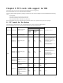
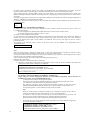
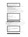
1.1 PCI cards for file devices
The following list describes the PCI cards that support DR for file devices (at the time of March 2005).
Please ask FUJITSU sales division about the newest information of cards that support DR.
Supporting Functions
Functions
Product ID
Software of driver
(driver name)
X6540A-U
Solaris OE (glm)
Hot replacement
Non kernel
memory
board
Kernel
memory
board
Hot
expansion
NG
(*1)
NG
(*1)
NG
(*1)
Redundant Software
None
*Multipath Disk Control 2.1
or later (*4)(*5)(*6) (*17)
X6541A-U
X6541A-X
Solaris OE (glm)
(*2)
NG
(*3)
NG
(*3)
OK
(*15)
*Multipath Disk Control
load balance option 2.1 or
later (*6)(*7)(*8)
*GR Multipath Driver 1.0.1
or later(*17) (*18)
*Multipath Disk Control 2.1
or later (*4)(*5)(*6) (*17)
GP7B8SC1U
GP7B8SC1X
Solaris OE (glm)
(*2)
OK
(*16)
OK
(*16)
OK
*Multipath Disk Control
load balance option 2.1 or
later (*6)(*7)(*8)
*GR Multipath Driver 1.0.1
or later(*17) (*18)
SCSI
PP028SC1U
PP028SC1X
FUJITSU PCI SCSI
Adapter Driver 1.0 or
later
(enclosed with a PCI
card)
Solaris OE (fjulsa)
(*9)(*10)
PW008SC3
FUJITSU ULTRA
LVD SCSI Host Bus
Adapter Driver 1.0 or
later
(enclosed with a PCI
card)
(*9)(*10)
OK
OK
OK
None
NG
(*3)
NG
(*3)
OK
(*15)
None
NG
(*3)
NG
(*3)
OK
(*15)
None
1
GP7B8FC1U
PW008FC2U
Fibre
Channel
FUJITSU PCI Fibre
Channel 2.2 or later
(enclosed with a PCI
card)
(*11)(*12) (*13)
FUJITSU PCI Fibre
Channel 2.2.1 or later
(enclosed with a PCI
card)
(*12) (*13)
*Multipath Disk Control 2.1
or later (*4)(*5)(*6) (*17)
OK
OK
OK
*Multipath Disk Control
load balance option 2.1 or
later (*6)(*7)(*8)
*GR Multipath Driver 1.0.1
or later(*17) (*18)
*Multipath Disk Control 2.1
or later (*4)(*5)(*6)(*16)
OK
OK
OK
*Multipath Disk Control
load balance option 2.1 or
later (*6)(*7)(*8)
*GR Multipath Driver 1.0.1
or later (*17) (*18)
*Multipath Disk Control 2.1
or later (*4)(*5)(*6) (*17)
FUJITSU PCI Fibre
Channel 2.2.1 Update2
or later
(enclosed with a PCI
card)
(*13)
OK
PW028FC4S
PW028FC4U
Emulex LightPulse FC
SCSI/IP 6.01f or later
OK
OK
OK
(*17)
PW028FC5S
PW028FC5U
Emulex LightPulse FC
SCSI/IP 6.01f or later
OK
OK
OK
(*17)
PW008FC3U
OK
OK
*Multipath Disk Control
load balance option 2.1 or
later (*6)(*7)(*8)
*GR Multipath Driver 1.0.1
or later (*17) (*18)
(*1) Replacement and expansion are not supported due to hardware specifications.
(*2) In case of using Solaris 8 OE, patch 109885-09 or later is needed.
(*3) Replacement is not supported due to hardware specifications.
(*4) In case of using Solaris 9 OE, Multipath Disk Control 2.2.1 or later is needed.
(*5) In case of using Multipath Disk Control 2.1, patches 911012-10 or later (MPHD) and 911013-12 or later (HDDV) are needed.
And in case of using Multipath Disk Control 2.2, patches 911258-03 or later (MPHD) and 911886-08 or later (HDDV) are needed.
Moreover in case of using Multipath Disk Control 2.2.1, patches 912629-02 or later (MPHD) and 910989-07 or later (HDDV) are
needed.
(*6) Multipath Disk Control and load balance option 2.2 are needed to hot expansion.
(*7) Multipath Disk Control load balance option is not supporting Solaris 9 OE or later.
(*8) In case of using Multipath Disk Control load balance option 2.1, patch 910990-01 or later is needed.
(*9) When using Solaris 8 OE, the patch 114632-04 or later is needed.
When applying the patch 114632-04 or later, if the patch 912773-02 or later has applied, it is necessary to remove the patch.
(*10) When using Solaris 9 OE, the patch 114951-03 or later is needed.
When applying the patch 114951-03 or later, if the patch 912774-01 or later has applied, it is necessary to remove the patch.
(*11) In case of using Solaris 9 OE, FUJITSU PCI Fibre Channel 2.2 (patchlevel 08) or later is needed.
(*12) In case of using FUJITSU PCI Fibre Channel 2.2, patch 910936-13 or later is needed. And in case of using FUJITSU PCI
Fibre Channel 2.2.1, patch 912069-09 or later is needed.
(*13) In case of using Solaris 10 OE, FUJITSU PCI Fibre Channel 3.0 or later is needed.
(*14) Redundant software should support Dynamic Reconfiguration function.
(*15) When connecting a shared device with a cluster system, please attach the system board after connecting the PCI card and
the shared device with each node of the cluster system.
(*16) When a shared device of non-multipath configuration is connected with a cluster system, it is necessary to stop the use of
the shared device from the active node of the cluster system.
(*17) This product is not supporting Solaris 10 OE in March 2005.
(*18) In case of using GR Multipath Driver 1.0.1 or later, patch 912651-11 or later is needed.
2
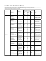
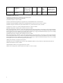
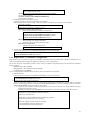
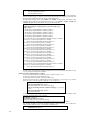
1.2 PCI cards for network devices
The following list describes the PCI cards that support DR for network devices (at the time of March 2005).
When using below PCI cards, please refer to "5.1.8 Network driver configuration changing". Please ask FUJITSU sales division
about the newest information of cards that support DR.
Supporting Functions
Functions
Ethernet
Product ID
(Functions)
Software of
driver
(driver name)
Hot replacement
Non
kernel
memory
board
Kernel
memory
board
(*1)
Hot
expansion
X1033A-U
X1033A-X
and Onboard LAN
interface (*2)
(10/100BASE-T)
Solaris OE (hme)
OK
OK
OK
X1034A-X
(10/100BASE-T x4)
Solaris OE (qfe)
NG
NG
NG
PW008FE1
(10/100BASE-T)
FUJITSU PCI
10/100 Ethernet
1.0 or later
(enclosed with a
PCI card) (*3)
PW008QE1
(10/100BASE-T x4)
FUJITSU PCI
Quad 10/100
Ethernet 1.0 or
later
(enclosed with a
PCI card)(*6)
PW008QE2
(10/100BASE-T x4)
FUJITSU PCI
Quad 10/100
Ethernet 1.1 or
later
(enclosed with a
PCI card)(*12)
OK
OK
OK
PP028GE1U
PP028GE1X
(1000BASE-SX)
FUJITSU PCI
Gigabit Ethernet
1.4.1 or later
(enclosed with a
PCI card) (*7)
OK
OK
OK
PW008GE1U
PW008GE1X
(1000BASE-T)
FUJITSU PCI
Gigabit Ethernet
1.4.1 or later
(enclosed with a
PCI card) (*7)
OK
OK
OK
PW008GE4
(1000BASE-SX)
*SynfinityLink 2.2
*PRIMECLUSTER
GLS 4.0 or later
*SynfinityLink 2.2
FUJITSU PCI
Gigabit Ethernet
2.0 or later
(enclosed with a
PCI card)(*8)
OK
OK
OK
OK
OK
OK
FUJITSU PCI
Gigabit Ethernet
2.0 or later
(enclosed with a
PCI card) (*8)
(*9)
*PRIMECLUSTER
GLS 4.0 or later
*SynfinityLink 2.2
(*4)
*PRIMECLUSTER
GLS 4.0 or later (*5)
*SynfinityLink 2.2
(*4)
*PRIMECLUSTER
GLS 4.0 or later (*5)
*SynfinityLink 2.2
(*4)
*PRIMECLUSTER
GLS 4.0 or later (*5)
*SynfinityLink 2.2
*PRIMECLUSTER
GLS 4.0 or later
*SynfinityLink 2.2
OK
OK
OK
(*9)
PW008GE5
(10/100/1000BASE-T)
Redundant Software
(*13)
OK
OK
OK
*PRIMECLUSTER
GLS 4.0 or later
*SynfinityLink 2.2
(*4)
*PRIMECLUSTER
GLS 4.0 or later (*5)
SynfinityLink 2.2
(*4)
PRIMECLUSTER
GLS 4.0 or later (*5)
3
ATM
GP7B8AT1U
GP7B8AT1X
(ATM)
FUJITSU PCI
ATM 1.2 or later
(enclosed with a
PCI card) (*14)
OK
OK
NG
(*10)
InfiniBand(*11)
PW028SY1
BLASTBAND
1.0 or later
OK
OK
OK
*SynfinityLink 2.2
*PRIMECLUSTER
GLS 4.0 or later
*PRIMECLUSTER
GLS 4.1A20 or later
(*1) The replacement of the kernel memory board is not supporting on the redundant system which used the SynfinityLink 2.2 and
the PRIMECLUSTER GLS 4.0.
(*2) The below machines have an Onboard LAN interface (hme).
- PRIMEPOWER 800/1000/2000, 900/1500/2500
(*3) Patch 912785-05 or later is needed.
(*4) The replacement and expansion are supported only on the Redundant Line Control Function.
(*5) When using the PRIMECLUSTER GLS 4.0 Multipath Function, patch 911872-03 or later is needed.
(*6) When using the "FUJITSU PCI Quad 10/100 Ethernet 1.0," patch 912216-09 or later is needed.
(*7) The driver version 1.4.1 or later and the patch 912214-03 or later are needed.
(*8) When using Solaris 8 OE, the patch 114536-03 or later is needed.
When applying the patch 114536-03 or later, if the patch 912314-01 or later has applied, it is necessary to remove the patch. When
removing the patch 912314-01 or 912314-02, the /platform/sun4us/kernel/drv/fjgi.conf file, which defines fjgi interface settings,
will be replaced. If you have edited fjgi.conf, please make a backup copy of fjgi.conf beforehand and pick up your own settings
and add them to the new one after removing the patch if necessary.
(*9) When using Solaris 9 OE, the patch 114994-03 or later is needed.
When applying the patch 114994-03 or later, if the patch 912660-01 or later has applied, it is necessary to remove the patch. When
removing the patch 912660-01 or 912660-02, the /platform/sun4us/kernel/drv/fjgi.conf file, which defines fjgi interface settings,
will be replaced. If you have edited fjgi.conf, please make a backup copy of fjgi.conf beforehand and pick up your own settings
and add them to the new one after removing the patch if necessary.
(*10) System rebooting is needed for hot expansion.
(*11) When PCI card is InfiniBand, please refer to "BLASTBAND GUIDE" for the procedure for replacement and expansion.
(*12) Patch 913294-03 or later is needed.
(*13) Redundant software is not supported on Solaris 10 OE.
(*14) In case of using Solaris 10 OE, FUJITSU PCI ATM 1.3 or later is needed.
4
Chapter 2 Outline of Replacement and Expansion
Procedure
This chapter provides the outline procedure of replacement or expansion of PCI cards by using DR.
2.1 Replacement Procedure
This section explains the outline procedure for replacement of PCI cards for non-redundant and redundant configurations by using
DR.
Please refer to the each redundant software manuals for more details on redundant configuration.
2.1.1 Replacement of non-redundant configuration
When the PCI cards are needed to be replaced in non-redundant configuration without using redundant software that controls the
multipath, it is necessary to stop all the high-level products (services) that are using these PCI cards on the system boards
equipped with the PCI cards and the connected devices.
The flow of the replacement procedure of PCI cards for non-redundant configuration is as follows.
Please refer to "Chapter 3 File Devices" and "Chapter 4 Network Devices" for detailed replacement procedure.
File devices procedures
1. Stop the daemons
If you use the Fibre Channel Card (PW028FC4/PW028FC5), stop the daemons.
2. Locating the PCI cards and the system boards
Locate the system boards equipped with the faulty PCI cards and the connected devices and interfaces.
3. Stopping the high-level products (services)
Stop all the high-level products that are using these PCI cards on the system boards equipped with the faulty PCI cards
and the connected devices.
4. Detaching the system boards
Detach the system boards equipped with the faulty PCI cards and enable the replacement of the PCI cards.
5. Replacing the PCI cards
Pull out the system boards equipped with the faulty PCI cards and replace the PCI cards, then mount back the system
boards.
6. Attaching the system boards
Attach the system boards equipped with the replaced PCI cards and enable the use of the PCI cards.
7. Restarting the high-level products (services)
Restart the high-level products that are stopped in step 3.
8. Start the daemons
If you use the Fibre Channel Card (PW028FC4/PW028FC5), start the daemons.
Network devices procedures
1. Locating the PCI cards and the system boards
Locate the system boards equipped with the faulty PCI cards and the connected devices and interfaces.
2. Stopping the high-level products (services)
Stop all the high-level products that are using these PCI cards on the system boards equipped with the faulty PCI cards
and the connected devices.
3. Detaching the system boards
Detach the system boards equipped with the faulty PCI cards and enable the replacement of the PCI cards.
4. Replacing the PCI cards
Pull out the system boards equipped with the faulty PCI cards and replace the PCI cards, then mount back the system
boards.
5. Attaching the system boards
Attach the system boards equipped with the replaced PCI cards and enable the use of the PCI cards.
6. Restarting the high-level products (services)
Restart the high-level products that are stopped in step 2.
2.1.2 Replacement of redundant configuration
When the PCI cards are needed to be replaced in redundant configuration with using redundant software that controls the
multipath, the PCI cards can be replaced without stopping the high-level products (services).
The flow of the replacement procedure of PCI cards for redundant configuration is as follows.
Please refer to "Chapter 3 File Devices" and "Chapter 4 Network Devices" for detailed replacement procedure.
5
File devices procedures
1. Stop the daemons
If you use the Fibre Channel Card (PW028FC4/PW028FC5), stop the daemons.
2. Locating the PCI cards and the system boards
Locate the system boards equipped with the faulty PCI cards and the connected devices and interfaces.
3. Disconnect from redundant system
Disconnect the devices path and interfaces of PCI cards from the redundant system.
4. Detaching the system boards
Detach the system boards equipped with the faulty PCI cards and enable the replacement of the PCI cards, then check the
multipath status.
5. Replacing the PCI cards
Pull out the system boards equipped with the faulty PCI cards and replace the PCI cards, then mount back the system
boards.
6. Attaching the system boards
Attach the system boards equipped with the replaced PCI cards and enable the use of the PCI cards, then check the
multipath status.
7. Connect to redundant system
Connect device paths and interfaces of the replaced PCI card to the redundant system.
If necessary, switch back the active paths.
8. Start the daemons
If you use the Fibre Channel Card (PW028FC4/PW028FC5), start the daemons.
Network devices procedures
1. Locating the PCI cards and the system boards
Locate the system boards equipped with the faulty PCI cards and the connected devices and interfaces.
2. Detaching the system boards
Detach the system boards equipped with the faulty PCI cards and enable the replacement of the PCI cards, then check the
multipath status.
3. Replacing the PCI cards
Pull out the system boards equipped with the faulty PCI cards and replace the PCI cards, then mount back the system
boards.
4. Attaching the system boards
Attach the system boards equipped with the replaced PCI cards and enable the use of the PCI cards, then check the
multipath status.If necessary, switch back the active paths.
2.2 Expansion Procedure
This section explains the outline procedure for expansion of PCI cards for non-redundant and redundant configurations by using
DR.
Please refer to the each redundant software manuals for more details on redundant configuration.
2.2.1 Expansion of non-redundant configuration
The flow of the expansion procedure of PCI cards for non-redundant configuration is as follows.
Please refer to "Chapter 3 File Devices" and "Chapter 4 Network Devices" for detailed expansion procedure.
File devices procedures
1. Reserving the definition of I/O devices that are expected to expand
In case of expanding file devices by using DR on Solaris 8 OE system, need to reserve the definition of I/O devices that
are expected to expand before system operation.
Please confirm the definition of I/O devices before the start of operation in this case.
2. Stop the daemons
If you use the Fibre Channel Card (PW028FC4/PW028FC5), stop the daemons.
3. Detaching the system boards
In case of expanding PCI cards on the existing system boards, choose the system boards and detach them.
4. Expanding the PCI cards
Expand the PCI cards on the choosed system boards and mount the system boards.
5. Attaching the system boards
Attach the system boards equipped with the expanded PCI cards and enable the use of the PCI cards.
In case of detaching the system boards in step 2, restart the stopped high-level products.
6. Start the daemons
If you use the Fibre Channel Card (PW028FC4/PW028FC5), start the daemons.
7. Preparation to recognize devices for Fibre Channel
If you use SAN management function, preparation to recognize devices.
8. Adding the setting of drivers
a. Adding the setting of the PCI card drivers
For file drivers, add the setting of the PCI card drivers.
6
b. Adding the setting of the device drivers
For file drivers, add the setting of the device drivers.
c. Add configure of PCI card driver
If you use the Fibre Channel Card (PW028FC4/PW028FC5), bind the auto mapped target connected with the
card.
9. Adding the setting of high-level products (services)
Add the setting of the high-level products with the expanded PCI cards.
10. Starting the high-level products (services)
Start the high-level products using the expanded PCI cards.
Network devices procedures
1. Reserving the definition of I/O devices that are expected to expand
In case of expanding file devices by using DR on Solaris 8 OE system, need to reserve the definition of I/O devices that
are expected to expand before system operation.
Please confirm the definition of I/O devices before the start of operation in this case.
2. Detaching the system boards
In case of expanding PCI cards on the existing system boards, choose the system boards and detach them.
3. Expanding the PCI cards
Expand the PCI cards on the choosed system boards and mount the system boards.
4. Attaching the system boards
Attach the system boards equipped with the expanded PCI cards and enable the use of the PCI cards.
In case of detaching the system boards in step 2, restart the stopped high-level products.
5. Expanding the devices
Connect the devices to the expanded PCI cards.
6. Adding the setting of drivers
a. Adding the setting of the PCI card drivers
For file drivers, add the setting of the PCI card drivers.
b. Adding the setting of the device drivers
For file drivers, add the setting of the device drivers.
7. Adding the setting of high-level products (services)
Add the setting of the high-level products with the expanded PCI cards.
8. Starting the high-level products (services)
Start the high-level products using the expanded PCI cards.
2.2.2 Expansion of new redundant configuration
The flow of the expansion procedure of PCI cards for new redundant configuration is as follows.
Please refer to "Chapter 3 File Devices" and "Chapter 4 Network Devices" for detailed expansion procedure.
File devices procedures
1. Reserving the definition of I/O devices that are expected to expand
In case of expanding file devices by using DR on Solaris 8 OE system, need to reserve the definition of I/O devices that
are expected to expand before system operation.
Please confirm the definition of I/O devices before the start of operation in this case.
2. Stop the daemons
If you use the Fibre Channel Card (PW028FC4/PW028FC5), stop the daemons.
3. Detaching the system boards
In case of expanding PCI cards on the existing system boards, choose the system boards and detach them.
4. Expanding the PCI cards
Expand the PCI cards on the choosed system boards and mount the system boards.
5. Attaching the system boards
Attach the system boards equipped with the expanded PCI cards and enable the use of the PCI cards.
In case of detaching the system boards in step 3, restart the stopped high-level products.
6. Start the daemons
If you use the Fibre Channel Card (PW028FC4/PW028FC5), start the daemons.
7. Preparation to recognize devices for Fibre Channel
If you use SAN management function, preparation to recognize devices.
8. Adding the setting of drivers
a. Adding the setting of the PCI card drivers
For file drivers, add the setting of the PCI card drivers.
b. Adding the setting of the device drivers
For file drivers, add the setting of the device drivers.
c. Add configure of PCI card driver
If you use the Fibre Channel Card (PW028FC4/PW028FC5), bind the auto mapped target connected with the
card.
9. Setup of the redundant configuration
Define the environment setting and start the use of the new expanded redundant configuration.
7
10. Adding the setting of high-level products (services)
Add the setting of the high-level products with the expanded PCI cards.
11. Starting the high-level products (services)
Start the high-level products using the expanded PCI cards.
Network devices procedures
1. Reserving the definition of I/O devices that are expected to expand
In case of expanding file devices by using DR on Solaris 8 OE system, need to reserve the definition of I/O devices that
are expected to expand before system operation.
Please confirm the definition of I/O devices before the start of operation in this case.
2. Detaching the system boards
In case of expanding PCI cards on the existing system boards, choose the system boards and detach them.
3. Expanding the PCI cards
Expand the PCI cards on the choosed system boards and mount the system boards.
4. Attaching the system boards
Attach the system boards equipped with the expanded PCI cards and enable the use of the PCI cards.
In case of detaching the system boards in step 2, restart the stopped high-level products.
5. Expanding the devices
Connect the devices to the expanded PCI cards.
6. Adding the setting of drivers
a. Adding the setting of the PCI card drivers
For file drivers, add the setting of the PCI card drivers.
b. Adding the setting of the device drivers
For file drivers, add the setting of the device drivers.
7. Setup of the redundant configuration
Define the environment setting and start the use of the new expanded redundant configuration.
8. Adding the setting of high-level products (services)
Add the setting of the high-level products with the expanded PCI cards.
9. Starting the high-level products (services)
Start the high-level products using the expanded PCI cards.
2.2.3 Expansion of PCI cards to redundant configuration
The flow of the expansion procedure of PCI cards for existing redundant configuration to reinforce redundancy is as follows.
Please refer to "Chapter 3 File Devices" and "Chapter 4 Network Devices" for detailed expansion procedure.
File devices procedures
1. Reserving the definition of I/O devices that are expected to expand
In case of expanding file devices by using DR on Solaris 8 OE system, need to reserve the definition of I/O devices that
are expected to expand before system operation.
Please confirm the definition of I/O devices before the start of operation in this case.
2. Stop the daemons
If you use the Fibre Channel Card (PW028FC4/PW028FC5), stop the daemons.
3. Detaching the system boards
In case of expanding PCI cards on the existing system boards, choose the system boards and detach them.
4. Expanding the PCI cards
Expand the PCI cards on the choosed system boards and mount the system boards.
5. Attaching the system boards
Attach the system boards equipped with the expanded PCI cards and enable the use of the PCI cards.
In case of detaching the system boards in step 3, restart the stopped high-level products.
6. Start the daemons
If you use the Fibre Channel Card (PW028FC4/PW028FC5), start the daemons.
7. Preparation to recognize devices for Fibre Channel
If you use SAN management function, preparation to recognize devices.
8. Adding the setting of drivers
a. Adding the setting of the PCI card drivers
For file drivers, add the setting of the PCI card drivers.
b. Adding the setting of the device drivers
For file drivers, add the setting of the device drivers.
c. Add configure of PCI card driver
If you use the Fibre Channel Card (PW028FC4/PW028FC5), bind the auto mapped target connected with the
card.
9. Attaching to the redundant configuration
Attach the I/O device paths and interfaces of the expanded PCI cards to the existing redundant configuration.
10. Switching over active paths
If necessary, switch over the active paths to the expanded PCI cards.
8
Network devices procedures
1. Reserving the definition of I/O devices that are expected to expand
In case of expanding file devices by using DR on Solaris 8 OE system, need to reserve the definition of I/O devices that
are expected to expand before system operation.
Please confirm the definition of I/O devices before the start of operation in this case.
2. Detaching the system boards
In case of expanding PCI cards on the existing system boards, choose the system boards and detach them.
3. Expanding the PCI cards
Expand the PCI cards on the choosed system boards and mount the system boards.
4. Attaching the system boards
Attach the system boards equipped with the expanded PCI cards and enable the use of the PCI cards.
In case of detaching the system boards in step 2, restart the stopped high-level products.
5. Expanding the devices
Connect the devices to the expanded PCI cards.
6. Adding the setting of drivers
a. Adding the setting of the PCI card drivers
For file drivers, add the setting of the PCI card drivers.
b. Adding the setting of the device drivers
For file drivers, add the setting of the device drivers.
7. Attaching to the redundant configuration
Attach the I/O device paths and interfaces of the expanded PCI cards to the existing redundant configuration.
8. Switching over active paths
If necessary, switch over the active paths to the expanded PCI cards.
9
10
Chapter 3 File Devices
This chapter provides the detail procedure of replacement or expansion of PCI cards for file devices by using DR.
Please refer to "Dynamic Reconfiguration User's Guide" for details of the drc(1M) command and the drcstat(1M) command used
in procedure of this chapter.
And refer to the each redundant software manual for more details on redundant configuration of PCI cards.
3.1 Replacement Procedure
This section explains the procedure for replacement of PCI cards for non-redundant and redundant configurations by using DR.
3.1.1 Replacement of non-redundant configuration
When the PCI cards are needed to be replaced in non-redundant configuration without using software that controls the multipath,
it is necessary to stop all the high-level products (services) as applications that are using these PCI cards on the system boards
equipped with the PCI cards and the connected devices.
The replacement procedures of PCI cards for non-redundant configuration are below.
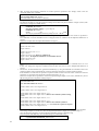
1. Stop the daemons
If you use the Fibre Channel Card (PW028FC4/PW028FC5), execute the following.
# /etc/rc0.d/K10hbanyware stop <Return>
# /etc/rc0.d/K10hbanywareDisc stop <Return>
2. Locating the PCI cards and the system boards
Using the following procedures, locate the system boards equipped with the faulty PCI cards and the all connected
devices.
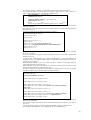
a. Locate the path interfaces connected the faulty PCI cards with I/O devices from the WARNING messages
information output to the console.
The following example shows that glm2 is the path inteface connected the faulty PCI card with I/O device.
:
WARNING: /pci@80,4000/scsi@2 (glm2):
invalid intcode=fe00
:
WARNING: /pci@80,4000/scsi@2/sd@3,0 (sd20):
SCSI transport failed: reason 'reset': giving up
:
If you use the Fibre Channel Card (PW028FC4/PW028FC5), the messages are shown as follows.
:
WARNING: lpfc0:INe:Adapter Hardware Error
:WARNING: /pci@89,4000/fibre-channel@2/sd@3,0 (sd20):
SCSI transport failed: reason 'reset': giving up
:
Exec the following command and check the physical path name.
# grep lpfc /etc/path_to_inst <Return>
"/pci@89,4000/fibre-channel@2" 0 "lpfc"
The second value is instance number of each lpfc instance.
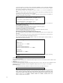
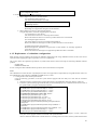
b. Locate the system board numbers for the path interfaces connected the faulty PCI cards with I/O devices in step
2.a (glm2) and display a list of devices under the system boards.
The system board number is the figure in the below red character part: XY (X represents the cabinet number, Y
represents the system board slot number in the cabinet).
Also, it is understood that the hme0 of network device ("/pci@83,4000/network@1,1" 0 "hme") excluding file
devices (sd1,sd20) exists on the relevant system board from the results of execution of the second command.
It is possible to ignore about se driver and scf driver (FJSVscfx) with the redundant configuration automatically.
Refer to "Enhanced Support Facility User's Guide" for details of se driver and scf driver.
# /opt/FJSVhwr/sbin/drcstat -device | grep /pci@80,4000/scsi@2 <Return>
00-PCI#0B "/pci@80,4000/scsi@2" 2 "glm"
00-PCI#0B "/pci@80,4000/scsi@2,1" 3 "glm"
00-PCI#0B "/pci@80,4000/scsi@2/sd@1,0" 1 "sd"
00-PCI#0B "/pci@80,4000/scsi@2/sd@3,0" 20 "sd"
# /opt/FJSVhwr/sbin/drcstat -device sb00 <Return>
00-PCI#0B "/pci@80,4000/scsi@2" 2 "glm"
00-PCI#0B "/pci@80,4000/scsi@2,1" 3 "glm"
00-PCI#0B "/pci@80,4000/scsi@2/sd@1,0" 1 "sd"
11
00-PCI#0B "/pci@80,4000/scsi@2/sd@3,0" 20 "sd"
00-ONBOARD "/pci@83,4000/ebus@1/FJSV,scfc@14,200000" 0 "FJSVscf2"
00-ONBOARD "/pci@83,4000/ebus@1/FJSV,se@14,400000" 0 "se"
00-ONBOARD "/pci@83,4000/network@1,1" 0 "hme"
In the following, the detach procedure is explained by taking sd20("/pci@80,4000/scsi@2/sd@3,0" 20 "sd") as
an example.
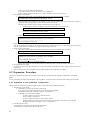
c. Determine the logical path under /dev/dsk corresponding to the /devices side path of sd20.
The following example shows that "c2t3d0" is the logical path corresponding to sd20.
# ls -l /dev/dsk | grep /pci@80,4000/scsi@2/sd@3,0 <Return>
lrwxrwxrwx 1 root root 41 Sep 20 22:53 c2t3d0s0
-> ../../devices/pci@80,4000/scsi@2/sd@3,0:a
lrwxrwxrwx 1 root root 41 Sep 20 22:53 c2t3d0s1
-> ../../devices/pci@80,4000/scsi@2/sd@3,0:b
lrwxrwxrwx 1 root root 41 Sep 20 22:53 c2t3d0s2
-> ../../devices/pci@80,4000/scsi@2/sd@3,0:c
lrwxrwxrwx 1 root root 41 Sep 20 22:53 c2t3d0s3
-> ../../devices/pci@80,4000/scsi@2/sd@3,0:d
lrwxrwxrwx 1 root root 41 Sep 20 22:53 c2t3d0s4
-> ../../devices/pci@80,4000/scsi@2/sd@3,0:e
lrwxrwxrwx 1 root root 41 Sep 20 22:53 c2t3d0s5
-> ../../devices/pci@80,4000/scsi@2/sd@3,0:f
lrwxrwxrwx 1 root root 41 Sep 20 22:53 c2t3d0s6
-> ../../devices/pci@80,4000/scsi@2/sd@3,0:g
lrwxrwxrwx 1 root root 41 Sep 20 22:53 c2t3d0s7
-> ../../devices/pci@80,4000/scsi@2/sd@3,0:h
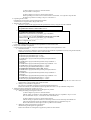
3. Stopping the high-level products (services)
Using the steps below, stop all the high-level products (services) that are using these PCI cards on the system boards
equipped with the faulty PCI cards and the connected devices.
When connecting network devices that are using as step 2.b, refer to "Chapter 4 Network Devices" about how to stop
them.
a. Please stop vold(1M).
# sh /etc/init.d/volmgt stop <Return>
b. Stop the use of the devices located in step 2.
[Disk devices (in file system operation)]
1) Determine the mount point of the target disk by using the logical path name (c2t3d0) in step
2.c.
# mount | grep c2t3d0 <Return>
/export/home on /dev/dsk/c2t3d0s3 setuid/read/write/largefiles on Mon
Sep 30 01:00:51 2002
/develop/firm on /dev/dsk/c2t3d0s0 setuid/read/write/largefiles on Mon
Sep 30 01:00:51 2002
/develop/drv on /dev/dsk/c2t3d0s1 setuid/read/write/largefiles on Mon
Sep 30 01:00:51 2002
/pub on /dev/dsk/c2t3d0s6 setuid/read/write/largefiles on Mon Sep 30
01:00:50 2002
2) Stop access to the target disk. To examine the process that uses the target file system, use the
fuser(1M) command as follows.
# fuser -c /export/home <Return>
/export/home: 14967c 14571c 14493ctm 14020c 13828tm 13803c
13575c 13133c 13125tm 13107c 12682ctm 12066tm 12048c 11971ctm
11952ctm 11937c 11867c 11846c 349m
3) Unmount the target disk.
# umount /export/home <Return>
# umount /develop/firm <Return>
# umount /develop/drv <Return>
# umount /pub <Return>
[Disk devices (in raw access operation) / Tape devices]
1) Check the access status of the target disk (sd20) in step 2.b up to now. This step is same for
tape devices.
# iostat -xc <Return>
extended device statistics cpu
device r/s w/s kr/s kw/s wait actv svc_t %w %b us sy wt id
12
sd 59.7 7.5 474.5 45.0 0.0 3.9 58.6 0 41 3 7 23 67
sd1 0.1 0.3 1.0 2.5 0.0 0.0 16.0 0 0
sd20 0.0 0.1 0.3 0.7 0.0 0.0 14.7 0 0
st82 0.0 0.0 0.0 0.0 0.0 0.0 0.0 0 0
nfs1 0.0 0.0 0.0 0.0 0.0 0.0 0.0 0 0
2) Stop access to the target disk from high-level products.
The access status to the target disk can be checked in the following way, the access status for one
minute is checked.
This step is same for tape devices.
# sar -d 60 1 <Return>
SunOS machine0 5.8 Generic_108528-05 sun4u 10/02/02
17:56:00 device %busy avque r+w/s blks/s avwait avserv
17:57:00 nfs1 0 0.0 0 0 0.0 0.0
sd0 2 0.3 2 37 0.0 145.5
sd0,a 1 0.1 0 5 0.0 301.4
sd0,b 0 0.0 0 9 0.0 31.5
sd0,c 0 0.0 0 0 0.0 0.0
sd0,d 1 0.0 0 4 0.0 126.8
sd0,e 0 0.0 0 0 0.0 0.0
sd0,f 1 0.1 1 6 0.0 120.9
sd0,g 1 0.1 1 14 0.0 111.7
:
sd20 0 0.0 0 0 0.0 0.0
sd20,a 0 0.0 0 0 0.0 0.0
sd20,c 0 0.0 0 0 0.0 0.0
sd20,g 0 0.0 0 0 0.0 0.0
:
st82 0 0.0 0 0 0.0 0.0
:
3) Stop (Detach) high-level products.
For details, refer to the manual for each product.
[Disk devices (swap device)]
1) Display the swap device list and check if the target disk of the logical path name (c2t3d0) in
step 2.c is a swap device.
# swap -l <Return>
swapfile dev swaplo blocks free
/dev/dsk/c2t3d0s4 32,164 16 788384 683680
2) Delete the swap device.
# swap -d /dev/dsk/c2t3d0s4 <Return>
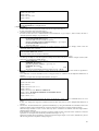
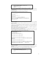
4. Detaching the system boards
Detach the system boards equipped with the faulty PCI cards by using the drc(1M) command, and check if the status of
the system boards is changed to "Unconfigured".
When the high-level products do not stop completely, the drc(1M) command terminates abnormally. So go back to step 3
again and stop the high-level products.
# /opt/FJSVhwr/sbin/drc -disconnect sb00 -keep <Return>
# /opt/FJSVhwr/sbin/drcstat -board sb00 <Return>
SB BN Status (Detail) PID Next_PID Board_Type CPU(MHz)
-- -- --------------- --- -------- ---------- -------00 0 Unconfigured 00 00 10 300
5. Replacing the PCI cards
Pull out the system boards detached in step 4 and replace the faulty PCI cards to replacement parts, then mount back the
system boards and connect cable to devices. A certified service engineer takes charge of this work.When replacing the
fibre channel PCI cards, the steps below are required.
[for PCI Fibre Channel(PW008FC3U/PW008FC2U/ GP7B8FC1U)]:
When using any of SAN management function of Systemwalker/StorageMGR, Softek SANView for ETERNUS
(except for Vixel) and SP5000 SRM Facility
No procedure is necessary. Go to step 6.
When not using SAN management function of the above products
In case of replacing of the fibre channel cards of the below environment setting, it is necessary to change the setting of the
fibre channel switch SN200 series and the disk array device ETERNUS3000/ETERNUS6000/GR700/800 series.
- Setting up the zoning by WWPN(World Wide Port Name) on SN200 series
- Using the host zoning (Host Affinity) function of ETERNUS3000/ETERNUS6000/GR700/800 series
13
For details, refer to the manual "Zoning User's Guide" and "ETERNUSmgr User Guide/GRmgr User Guide". If you use
the Fibre Channel switch or disk array device other than described above, see the document of each product.
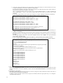
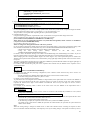
When changing the above setting, WWPNs (Figures of sixteen digits in all) of the replacement parts are needed. The
WWPN of the replacement fibre channel card is determined by using eight-digit number printed on the seal of the card on
front plate.
This figure of eight digit represents the lower eight digit of WWPN by the hexadecimal number. The upper eight digit of
WWPN is 10000000 by a fixed hexadecimal number.
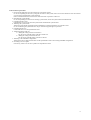
For instance, when the following seal puts on the replacement fibre channel card, the WWPN of the replacement card is
100000000e244061.
0e24
4061
[ for Fibre Channel Card (PW028FC4/PW028FC5)]:
To replace PCI cards with the following configurations, Fibre Channel switch and disk array device need to be
reconfigured individually.
- If zone configuration by WWPN (World Wide Port Name) is done on Fibre Channel switch.
- If the Host Zoning function of disk array device is used.
For details, see the document of each product.
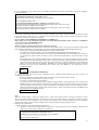
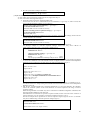
To perform the above reconfiguration, the WWPN(a 16-digit number) of the replacement card is needed. The WWPN of
the PCI card can be known from the twelve characters shown on a label on the back of the card. These characters
represent the bottom twelve digits of the WWPN in hexadecimal form. The top four digits are fixed to 1000 in
hexadecimal form.
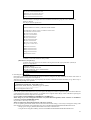
For example, if the following label is shown on the back of the card, the WWPN of the replacement card is
10000000c9366037.
IEEE:0000c9366037
Note
When the zoning setting is changed in SN200 series or other Fibre Channel switch, executing I/O requests to other
devices sometimes terminate abnormally with temporary errors by the setting changes.
I/O requests to disk array devices and the like are recovered normally by retry processes, but backup processes of fibre
channel tape devices sometimes terminate abnormally.
Please execute the change of the zoning setting after stopping backup processes.
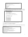
6. Attaching the system boards
Using the steps below, attach the detached system board.
a. Attach the system boards equipped with the replaced PCI cards by using the drc(1M) command, and check if the
status of the system boards is changed to "Configured".
# /opt/FJSVhwr/sbin/drc -connect sb00 <Return>
# /opt/FJSVhwr/sbin/drcstat -board sb00 <Return>
SB BN Status (Detail) PID Next_PID Board_Type CPU(MHz)
-- -- --------------- --- -------- ---------- -------00 0 Configured 00 00 10 300
b. When replacing the fibre channel PCI cards, the steps below are required.
[for PCI Fibre Channel(PW008FC3U/PW008FC2U/ GP7B8FC1U)]:
When using any of SAN management function of Systemwalker/StorageMGR, Softek SANView for
ETERNUS (except for Vixel) and SP5000 SRM Facility
1) Refresh current condition on management window.
SAN (Storage Area Network) management function searchs and indicates replaced PCI card.
Use "Inherit of Access Path" function on management window.
This function will adjust switch zoning and host affinity function of disk array device
ETERNUS3000/ETERNUS6000/GR700/800 series with new WWPN of replaced PCI card.
See "Operation guide" or "User's Manual" of each product for details.
Note
When the zoning setting is changed in SN200 series, executing I/O requests to other devices
sometimes terminate abnormally with temporary errors by the setting changes.
I/O requests to disk array devices and the like are recovered normally by retry processes, but
backup processes of fibre channel tape devices sometimes terminate abnormally.
Please execute the change of the zoning setting after stopping backup processes.
2) Reattach the system boards equipped with the replaced PCI cards with changed zonig setting
by using the following commands.
# /opt/FJSVhwr/sbin/drc -disconnect sb00 -keep <Return>
# /opt/FJSVhwr/sbin/drc -connect sb00 <Return>
# /opt/FJSVhwr/sbin/drcstat -board sb00 <Return>
SB BN Status (Detail) PID Next_PID Board_Type CPU(MHz)
14
-- -- --------------- --- -------- ---------- -------00 0 Configured 00 00 10 300
If you don't use SAN management function of the above products
No procedure is necessary.
[ for Fibre Channel Card (PW028FC4/PW028FC5)]:
No procedure is necessary.
7. Restarting the high-level products (services)
Using the steps below, restart the stopped high-level products.
When stopping network devices in step 3, refer to "Chapter 4 Network Devices" about how to restart them.
a. Please start vold(1M).
# sh /etc/init.d/volmgt start <Return>
b. Restart the use of the devices stopped in step 3.b.
[Disk devices (in file system operation)]
· Mount the unmounted file systems and restart the use.
# mount -F ufs /dev/dsk/c2t3d0s3 /export/home <Return>
# mount -F ufs /dev/dsk/c2t3d0s0 /develop/firm <Return>
# mount -F ufs /dev/dsk/c2t3d0s1 /develop/drv <Return>
# mount -F ufs /dev/dsk/c2t3d0s6 /pub <Return>
[Disk devices (in raw access operation) / Tape devices]
· Reactivate high-level products and restart.
For details, refer to the manual for each product.
[Disk devices (swap device)]
· Add the swap devices and restart the use.
# /sbin/swapadd -2 <Return>
8. Start the daemons
If you use the Fibre Channel Card (PW028FC4/PW028FC5), execute the following.
# /etc/rc2.d/S99hbanyware start <Return>
# /etc/rc2.d/S99hbanywareDisc start <Return>
3.1.2 Replacement of redundant configuration
When the PCI cards are needed to be replaced in redundant configuration with using software that controls the multipath, the PCI
cards can be replaced without stopping the high-level products (services) as applications.
This section shows the replacement procedure of PCI cards for redundant configuration with using the following redundant
software products.
· Multipath Disk Control (MPHD)
· Multipath Disk Control load balance option (MPLB)
· GR Multipath Driver (GRMPD)
In case of using the other redundant software products, refer to the manual for each product.
1. Stop the daemons
If you use the Fibre Channel Card (PW028FC4/PW028FC5), execute the following.
# /etc/rc0.d/K10hbanyware stop <Return>
# /etc/rc0.d/K10hbanywareDisc stop <Return>
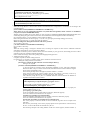
2. Locating the PCI cards and the system boards
Using the following procedures, locate the system boards equipped with the faulty PCI cards and the all connected
devices. The following procedure is described for MPHD/MPLB/GRMPD. If you use the redundancy software other than
MPHD/MPLB/GRMPD, see the document for each product.
a. Locate the path interfaces connected the faulty PCI cards with I/O devices from the WARNING messages
information output to the console.
The following example shows that fjpfca3 is the path inteface connected the faulty PCI card with I/O device.
:
WARNING: /pci@80,4000/fibre-channel@1 (fjpfca3):
Hard Error : PCI DMA error.
:
WARNING: /pci@80,4000/fibre-channel@1/hddv@1,0 (hddv1):
SCSI transport failed: reason 'reset': giving up
:
NOTICE: mphd0: I/O path switchover succeeded.
/pci@80,4000/fibre-channel@1/hddv@1,0 =>
/pci@84,4000/fibre-channel@1/hddv@2,0
:
In the following explanation we assume that above messages were printed out on the console.
15
b. Locate the system board numbers for the path interfaces connected the faulty PCI cards with I/O devices in step
1.a (fjpfca3) and display a list of devices under the system boards.
The system board number is the figure in the below red character part: XY (X represents the cabinet number, Y
represents the system board slot number in the cabinet).
Also, it is understood that the hme0 of network device ("/pci@83,4000/network@1,1" 0 "hme") excluding file
devices (hddv1,hddv2,..) exists on the relevant system board from the results of execution of the second
command.
It is possible to ignore about se driver and scf driver (FJSVscfx) with the redundant configuration automatically.
Refer to "Enhanced Support Facility User's Guide" for details of se driver and scf driver.
# /opt/FJSVhwr/sbin/drcstat -device | grep /pci@80,4000/fibre-channel@1 <Return>
00-PCI#0B "/pci@80,4000/fibre-channel@1" 3 "fjpfca"
00-PCI#0B "/pci@80,4000/fibre-channel@1/hddv@1,0" 1 "hddv"
00-PCI#0B "/pci@80,4000/fibre-channel@1/hddv@1,1" 2 "hddv"
:
# /opt/FJSVhwr/sbin/drcstat -device sb00 <Return>
00-PCI#0B "/pci@80,4000/fibre-channel@1" 3 "fjpfca"
00-PCI#0B "/pci@80,4000/fibre-channel@1/hddv@1,0" 1 "hddv"
00-PCI#0B "/pci@80,4000/fibre-channel@1/hddv@1,1" 2 "hddv"
:
00-ONBOARD "/pci@83,4000/ebus@1/FJSV,scfc@14,200000" 0 "FJSVscf2"
00-ONBOARD "/pci@83,4000/ebus@1/FJSV,se@14,400000" 0 "se"
00-ONBOARD "/pci@83,4000/network@1,1" 0 "hme"
In the following, the detach procedure is explained by taking hddv1("/pci@80,4000/fibre-channel@1/hddv@1,0"
1 "hddv") as an example.
c. Find hddv1 with the "offline fail" status from the results of execution of the iompadm command and determine
the logical path name corresponding to the faulty path connected hddv1 (the character string from 'c' to 'd' under
/dev/rdsk).
The following example is the results of execution of MPHD and shows that "c3t1d0" is the logical path name
corresponding to the faulty path.
In case of using MPLB or GRMPD, specify the "mplb" as -c option parameter of the iompadm command.
In case of updated GRMPD from MPHD, specify the "mphd" as -c option parameter of the iompadm command.
# /usr/opt/FJSViomp/bin/iompadm -c mphd -p info <Return>
:
IOMP: /dev/FJSVmphd/fiomp/adm2
-> /devices/pseudo/mphd@2:adm
Element:
/dev/rdsk/c3t1d0s2 offline fail block "target completed hard reset sequence [GR7104546010000-00-00-30] (hddv1)"
-> /devices/pci@80,4000/fibre-channel@1/hddv@1,0:c,raw
/dev/rdsk/c2t2d0s2 online active block "good status with active [GR7104546010000-01-01-32] (hddv15)"
-> /devices/pci@84,4000/fibre-channel@1/hddv@2,0:c,raw
Node:
/dev/FJSVmphd/rdsk/mphd2s0
/dev/FJSVmphd/rdsk/mphd2s1
/dev/FJSVmphd/rdsk/mphd2s2
/dev/FJSVmphd/rdsk/mphd2s3
/dev/FJSVmphd/rdsk/mphd2s4
/dev/FJSVmphd/rdsk/mphd2s5
/dev/FJSVmphd/rdsk/mphd2s6
/dev/FJSVmphd/rdsk/mphd2s7
Function:
MPmode=false
AutoPath=true
Block=true
NeedSync=false
:
3. Disconnect from redundant system
In the case of MPHD/MPLB/GRMPD, the path is disconnected from redundant system automatically when the system
boards are detached.If you use the redundancy software other than MPHD/MPLB/GRMPD, see the document for each
product.
4. Detaching the system boards
Detach the system boards equipped with the faulty PCI cards by using the drc(1M) command, and check if the status of
the system boards is changed to "Unconfigured".
In addition, check if the status of the all LUNs (Logical Unit Number) under the logical path in step 2.c is changed to
"unconfigured disconnected".
16
In case of detaching an active path of the active/standby configuration, the status of the standby side path is changed to
active automatically.
# /opt/FJSVhwr/sbin/drc -disconnect sb00 -keep <Return>
# /opt/FJSVhwr/sbin/drcstat -board sb00 <Return>
SB BN Status (Detail) PID Next_PID Board_Type CPU(MHz)
-- -- --------------- --- -------- ---------- -------00 0 Unconfigured 00 00 10 300
# /usr/opt/FJSViomp/bin/iompadm -c mphd info | grep c3t1d <Return>
/dev/rdsk/c3t1d0s2 unconfigured disconnected unblock "changing parts with power supply
charged [GR7104546- 010000-00-00-30] (hddv1)"
/dev/rdsk/c3t1d1s2 unconfigured disconnected unblock "changing parts with power supply
charged [GR7104546- 010000-00-00-30] (hddv2)"
:
5. Replacing the PCI cards
Pull out the system boards detached in step 4 and replace the faulty PCI cards to new parts, then mount back the system
boards and connect cable to devices. A certified service engineer takes charge of this work.When replacing the fibre
channel PCI cards, the steps below are required.
[for PCI Fibre Channel(PW008FC3U/PW008FC2U/ GP7B8FC1U)]:
When using any of SAN management function of Systemwalker/StorageMGR, Softek SANView for ETERNUS
(except for Vixel) and SP5000 SRM Facility
No procedure is necessary. Go to step 6.
When not using SAN management function of the above products
In case of replacing of the fibre channel cards of the below environment setting, it is necessary to change the setting of the
fibre channel switch SN200 series and the disk array device ETERNUS3000/ETERNUS6000/GR700/800 series.
- Setting up the zoning by WWPN(World Wide Port Name) on SN200 series
- Using the host zoning (Host Affinity) function of ETERNUS3000/ETERNUS6000/GR700/800 series
For details, refer to the manual "Zoning User's Guide" and "ETERNUSmgr User Guide/GRmgr User Guide". If
you use the Fibre Channel switch or disk array device other than described above, see the document of each
product.
When changing the above setting, WWPNs (Figures of sixteen digits in all) of the replacement parts are needed.
The WWPN of the replacement fibre channel card is determined by using eight-digit number printed on the seal
of the card on front plate.This figure of eight digit represents the lower eight digit of WWPN by the hexadecimal
number. The upper eight digit of WWPN is 10000000 by a fixed hexadecimal number.For instance, when the
following seal puts on the replacement fibre channel card, the WWPN of the replacement card is
100000000e244061.
0e24
4061
[ for Fibre Channel Card (PW028FC4/PW028FC5)]:
To replace PCI cards with the following configurations, Fibre Channel switch and disk array device need to be
reconfigured individually.
- If zone configuration by WWPN (World Wide Port Name) is done on Fibre Channel switch.
- If the Host Zoning function of disk array device is used.
For details, see the document of each product.
To perform the above reconfiguration, the WWPN(a 16-digit number) of the replacement card is needed. The
WWPN of the PCI card can be known from the twelve characters shown on a label on the back of the card. These
characters represent the bottom twelve digits of the WWPN in hexadecimal form. The top four digits are fixed to
1000 in hexadecimal form.For example, if the following label is shown on the back of the card, the WWPN of the
replacement card is 10000000c9366037.
IEEE:0000c9366037
Note
When the zoning setting is changed in SN200 series or other Fibre Channel switch, executing I/O requests to other
devices sometimes terminate abnormally with temporary errors by the setting changes. I/O requests to disk array devices
and the like are recovered normally by retry processes, but backup processes of fibre channel tape devices sometimes
terminate abnormally. Please execute the change of the zoning setting after stopping backup processes.
6. Attaching the system boards
Using the steps below, attach the detached system board.
a. Attach the system boards equipped with the replaced PCI cards by using the drc(1M) command, and check if the
status of the system boards is changed to "Configured".
# /opt/FJSVhwr/sbin/drc -connect sb00 <Return>
# /opt/FJSVhwr/sbin/drcstat -board sb00 <Return>
SB BN Status (Detail) PID Next_PID Board_Type CPU(MHz)
-- -- --------------- --- -------- ---------- -------00 0 Configured 00 00 10 300
17
b. When replacing the fibre channel PCI cards, the steps below are required.
[for PCI Fibre Channel (PW008FC3U/PW008FC2U/ GP7B8FC1U) ]:
When using any of SAN management function of Systemwalker/StorageMGR, Softek SANView for
ETERNUS (except for Vixel) and SP5000 SRM Facility
Refresh current condition on management window.
SAN (Storage Area Network) management function searchs and indicates replaced PCI card.
Use "Inherit of Access Path" function on management window.
This function will adjust switch zoning and host affinity function of disk array device
ETERNUS3000/ETERNUS6000/GR700/800 series with new WWPN of replaced PCI card.
See "Operation guide" or "User's Manual" of each product for details.
Note
When the zoning setting is changed in SN200 series, executing I/O requests to other devices
sometimes terminate abnormally with temporary errors by the setting changes.
I/O requests to disk array devices and the like are recovered normally by retry processes, but
backup processes of fibre channel tape devices sometimes terminate abnormally.
Please execute the change of the zoning setting after stopping backup processes.
Reattach the system boards equipped with the replaced PCI cards with changed zonig setting by
using the following commands.
# /opt/FJSVhwr/sbin/drc -disconnect sb00 -keep <Return>
# /opt/FJSVhwr/sbin/drc -connect sb00 <Return>
# /opt/FJSVhwr/sbin/drcstat -board sb00 <Return>
SB BN Status (Detail) PID Next_PID Board_Type CPU(MHz)
-- -- --------------- --- -------- ---------- -------00 0 Configured 00 00 10 300
If you don't use SAN management function of the above products
No procedure is necessary.
[ for Fibre Channel Card (PW028FC4/PW028FC5)]:
No procedure is necessary.
c. Check if the status of the all LUNs under the logical path in step 1.c is changed to "online active" or "online
standby".
When switching over the active path in step 2, switch back to the original active side automatically.
# /usr/opt/FJSViomp/bin/iompadm -c mphd info | grep c3t1d <Return>
/dev/rdsk/c3t1d0s2 online active block "good status with active [GR7104546010000-00-00-30] (hddv1)"
/dev/rdsk/c3t1d1s2 online active block "good status with active [GR7104546010000-00-00-30] (hddv2)"
:
7. Connect to redundant system
In the case of MPHD/MPLB/GRMPD, the path is connected to redundant system automatically when the system boards
are attached. If you use the redundancy software other than MPHD/MPLB/GRMPD, see the document for each product.
8. Start the daemons
If you use the Fibre Channel Card (PW028FC4/PW028FC5), execute the following.
# /etc/rc2.d/S99hbanyware start <Return>
# /etc/rc2.d/S99hbanywareDisc start <Return>
3.2 Expansion Procedure
This section explains the procedure for expansion of PCI cards for non-redundant and redundant configurations by using DR in
case of Solaris 8 OE and Solaris 9 OE or later.
The difference of the both procedures is as follows.
In Solaris 8 OE, it is necessary to reserve the definition of I/O devices that are expected to expand beforehand before system
operation, but in Solaris 9 OE or later, this procedure is not required..
3.2.1 Solaris 8 OE
This section explains the procedure for expansion of PCI cards on Solaris 8 OE system.
To expand by using DR on Solaris 8 OE, it is necessary to reserve the definition of I/O devices that are expected to expand
beforehand and restart the system.
When the I/O devices to expand are already defined, the reserved definition is not required. So omit the following procedure of
step 1.
18
If you use Fibre Channel Card (PW028FC4/PW028FC5), ensure the automap function is effective. Boot the system after
modifying lpfc.conf.
# vi /kernel/drv/lpfc.conf <Return>
:
# If automap is set, SCSI IDs for all FCP nodes without
# persistent bindings will be automatically generated.
# If new FCP devices are added to the network when the system is down,
# there is no guarantee that these SCSI IDs will remain the same
# when the system is booted again.
# The bind method of the port is used as the binding method of
# automap devices to preserve SCSI IDs between link down and link up.
# If automap is 0, only devices with persistent bindings will be
# recognized by the system.
automap=1; <- set to 1
3.2.1.1 Expansion of non-redundant configuration
This section shows the flow of the procedure PCI cards expansion for non-redundant configuration on Solaris 8 OE system.
1. Reserving the definition of I/O devices that are expected to expand
Using the following procedures for each device type, reserve the definition of I/O devices that are expected to expand.
When the I/O devices are not defined, it is not possible to expand by using DR.
So please define them before system operation is started.
[Disk Devices/Tape Devices (Solaris OE:sd/st)]
In the following, the procedure is explained by taking the reserved definition of the disk device (target=2 lun=0) as an
example.
For tape devices, execute the same operations with replacing "sd" of the following procedures to "st".
a. Refer to the file "/kernel/drv/sd.conf", and check if the "target=2, lun=0" is defined.
If this definition does not exist, add this, and if this definition is treated as comment, remove the comment
symbols.
· [Disk Devices]
# vi /kernel/drv/sd.conf <Return>
:
name="sd" class="scsi"
target=0 lun=0;
:
name="sd" class="scsi" <------ If undefined, add this definition
target=2 lun=0; <------ or remove the comment symbols.
:
· [Tape Devices]
# vi /kernel/drv/st.conf <Return>
:
name="st" class="scsi"
target=0 lun=0;
:
name="st" class="scsi" <------ If undefined, add this definition
target=5 lun=0; <------ or remove the comment symbols.
:
b. In case of updating the file "/kernel/drv/sd.conf" in step 1.a, reconfigure the kernel and restart the system.
In case of not updating in step 1.a, this procedure is not required.
# touch /reconfigure <Return>
# /usr/sbin/shutdown -y -i6 -g0 <Return>
[Disk Array devices (Hard Disk Driver:hddv)]
In the following, the procedure is explained by taking the reserved definition of the disk array device (target=3 lun=0 to
2) as an example.
- In case of first reserved expansion of disk array devices, begin from step 1.a.
- In case of second or later, begin from step 1.e.
a. Check the presence of the file "/kernel/drv/hddv.conf".
If it does not exist, this case is "Hard Disk Driver first installation", so go to step 1.c, and if it exists, this case is
"non-hot expansion settings", so go to step 1.b.
[In case of not existing (first installation)] --> go to step 1.c
# ls /kernel/drv/hddv.conf <Return>
/kernel/drv/hddv.conf: No such file or directory
[In case of existing (non-hot expansion settings)] --> go to step 1.b
# ls /kernel/drv/hddv.conf <Return>
/kernel/drv/hddv.conf
19
b. After executing the following command on non-hot expansion specified in the settings, check if the file
"/kernel/drv/hddv.conf" is deleted.
# hddvadm -i <Return>
# ls /kernel/drv/hddv.conf <Return>
/kernel/drv/hddv.conf: No such file or directory
c. Using the following command, create the hddv.conf file for reserved expansion function.
The message example in "Non-hot expansion settings" shows disk array device GR720 of target=1(lun=0) with
using now is overlapped in sd/hddv drivers.
· [First installation] --> go to step 1.e
# hddvadm -M <Return>
· [Non-hot expansion settings] --> go to step 1.d
# hddvadm -M <Return>
already
ID=
1
exists.
/devices/pci@1d,2000/fibre-channel@1/sd@1,0:a,raw : GR720
d. When the reserved expansion function is used, the target IDs registered in hddv.conf cannot be registered in
sd.conf.
So if definition in sd.conf and hddv.conf are overlapped, delete or comment out the duplicated definitions of
sd.conf.
The below example shows the duplicated definition of target=1.
# vi /kernel/drv/sd.conf <Return>
:
name="sd" class="scsi"
target=0 lun=0;
:
#name="sd" class="scsi" <-----target=1 lun=0;
#name="sd" class="scsi" Delete or comment out
target=1 lun=1; the duplicated definitions of sd and hddv drivers.
#name="sd" class="scsi"
target=1 lun=2; <-----:
But it is impossible to delete the target IDs being recognized as a system volume a CD-ROM device etc. in sd
driver.
In this case, change the target ID on hddv.conf and the disk array device side to unduplicated definition of
sd.conf.
e. Edit the file "/kernel/drv/hddv.conf" generated automatically by using the hddvadm -M command, remove the
comment symbols of the LUN definitions of reserved expansion and using in non-hot expansion settings.
If the definition of LUNs that are expected to expand is found, because of second or later execution of reserved
expansion, it is not required to execute the procedures from step 1.f to 1.g.
The below example shows registrations of reserved expansion targets (target=3, lun=0 to 2) and disk array device
GR720 using in non-hot expansion settings (target=1)
# ls /kernel/drv/hddv.conf <Return>
/kernel/drv/hddv.conf
# vi /kernel/drv/hddv.conf <Return>
:
#name="hddv" class="scsi" target=0 lun=0;
:
#name="hddv" class="scsi" target=0 lun=7;
:
name="hddv" class="scsi" target=1 lun=0; <-----name="hddv" class="scsi" target=1 lun=1; Remove the comment symbols of using
LUNs
name="hddv" class="scsi" target=1 lun=2; <-----:
name="hddv" class="scsi" target=3 lun=0; <-----name="hddv" class="scsi" target=3 lun=1; Remove the comment symbols of
name="hddv" class="scsi" target=3 lun=2; <------ LUNs that are expected to expand
#name="hddv" class="scsi" target=3 lun=3;
:
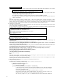
f. Check if no duplicate definitions exist in the sd.conf and hddv.conf files by using the hddvchk_conf command.
The message example in "Check NG" shows the duplicated definition is target=3, so go back to step 1.d.
Also, the following example is execution when the FJSVhddv package is installed to /opt.
The placed path of the hddvchk_conf command changes by installed directory.
· [Check OK] --> go to step 1.g
# /opt/FJSVhddv/bin/hddvchk_conf <Return>
20
/kernel/drv/sd.conf and /kernel/drv/hddv.conf seems to be correct
· [Check NG] --> go back to step 1.d
# /opt/FJSVhddv/bin/hddvchk_conf <Return>
NG ID = [ 3 ]
g. Reconfigure the kernel and restart the system.
# touch /reconfigure <Return>
# /usr/sbin/shutdown -y -i6 -g0 <Return>
2. Stop the daemons
If you use the Fibre Channel Card (PW028FC4/PW028FC5), execute the following.
# /etc/rc0.d/K10hbanyware stop <Return>
# /etc/rc0.d/K10hbanywareDisc stop <Return>
3. Detaching the system boards
In case of expanding PCI cards on the existing system boards, choose the system boards of expansion target and detach
the system boards according to step 3 to 4 in Section 3.1.1 or step 4 in Section 3.1.2.
This procedure is not required when expanding the new system boards together.
4. Expanding the PCI cards
Using the following procedures, expand the PCI cards. A certified service engineer takes charge of this work.
When expanding the fibre channel PCI cards, the steps below are required.
[for PCI Fibre Channel(PW008FC3U/PW008FC2U/ GP7B8FC1U)]:
When using any of SAN management function of Systemwalker/StorageMGR, Softek SANView for ETERNUS
(except for Vixel) and SP5000 SRM Facility
No procedure is necessary. Go to step 6.
When not using SAN management function of the above products
In case of replacing of the fibre channel cards of the below environment setting, it is necessary to change the setting of the
fibre channel switch SN200 series and the disk array device ETERNUS3000/ETERNUS6000/GR700/800 series.
- Setting up the zoning by WWPN on the fibre channel switch SN200 series
- Using
the
host
zoning
(Host
Affinity)
function
of
the
disk
array
device
ETERNUS3000/ETERNUS6000GR700/800 series
For details, refer to the manual "Zoning User's Guide" and "ETERNUSmgr User Guide/GRmgr User Guide". If you use
the Fibre Channel switch or disk array device other than described above, see the document of each product.
When changing the above setting, WWPNs (Figures of sixteen digits in all) of the replacement parts are needed. The
WWPN of the expansion fibre channel card is determined by using eight-digit number printed on the seal of the card on
front plate.
This figure of eight digit represents the lower eight digit of WWPN by the hexadecimal number. The upper eight digit of
WWPN is 10000000 by a fixed hexadecimal number.
For instance, when the following seal puts on the expansion fibre channel card, the WWPN of the expansion card is
100000000e244061.
0e24
4061
[ for Fibre Channel Card (PW028FC4/PW028FC5)]:
To replace PCI cards with the following configurations, Fibre Channel switch and disk array device need to be
reconfigured individually.
- If zone configuration by WWPN (World Wide Port Name) is done on Fibre Channel switch.
- If the Host Zoning function of disk array device is used.
For details, see the document of each product.
To perform the above reconfiguration, the WWPN(a 16-digit number) of the replacement card is needed. The WWPN of
the PCI card can be known from the twelve characters shown on a label on the back of the card. These characters
represent the bottom twelve digits of the WWPN in hexadecimal form. The top four digits are fixed to 1000 in
hexadecimal form.
For example, if the following label is shown on the back of the card, the WWPN of the replacement card is
10000000c9366037.
IEEE:0000c9366037
a. Before expanding the PCI cards, save the results of execution of the drcstat(1M) command in a file (current
configuration information).
# /opt/FJSVhwr/sbin/drcstat -device > /tmp/drcstat.pre <Return>
b. Choose the system boards for expansion target of PCI cards and the equipped slots, then expand the PCI cards
and mount the system boards and connect cable to devices.
A certified service engineer takes charge of this work.
In the following example, the expansion of PCI cards to the system board: sb00 is explained.
The format of the system board is sbXY (X represents the cabinet number, Y represents the system board slot
number in the cabinet).
Note
When the zoning setting is changed in SN200 series or other Fibre Channel switch, executing I/O requests to other
devices sometimes terminate abnormally with temporary errors by the setting changes. I/O requests to disk array devices
21
and the like are recovered normally by retry processes, but backup processes of fibre channel tape devices sometimes
terminate abnormally. Please execute the change of the zoning setting after stopping backup processes.
5. Attaching the system boards
Attach the system boards equipped with the expanded PCI cards by using the drc(1M) command, and check if the status
of the system boards is changed to "Configured".
In case of detaching the system boards in step 3, restart the stopped high-level products and check the multipath status
according to step 7 in Section 3.1.1 or step 2.c in Section 3.1.2.
# /opt/FJSVhwr/sbin/drc -connect sb00 <Return>
# /opt/FJSVhwr/sbin/drcstat -board sb00 <Return>
SB BN Status (Detail) PID Next_PID Board_Type CPU(MHz)
-- -- --------------- --- -------- ---------- -------00 0 Configured 00 00 10 300
6. Start the daemons
If you use the Fibre Channel Card (PW028FC4/PW028FC5), execute the following.
# /etc/rc2.d/S99hbanyware start <Return>
# /etc/rc2.d/S99hbanywareDisc start <Return>
7. Preparation to recognize devices for Fibre Channel
When the zoning function is used on fiber channel switch SN200 series configuration, it is necessary to set zoning to the
expanded devices.
[for PCI Fibre Channel(PW008FC3U/PW008FC2U/ GP7B8FC1U)]:
When using any of SAN management function of Systemwalker/StorageMGR, Softek SANView for ETERNUS
(except for Vixel) and SP5000 SRM Facility
WWPN zoning of SN200 series, Host affinity of Array disk device ETERNUS3000/ETERNUS6000/GR700/800 series
and binding setting for fjpfca.conf/sd.conf of host can be added from SAN management window automatically.
See "Operation guide" or "User's Manual" of each product for details.
Before using this function, the following step 8.a.1) and 8.a.2) [except fcp-bind-target setting] are necessary.
Moreover, begin from step 8.a.3) after executing this function.
When not using SAN management function of the above products
No procedure is necessary.
[ for Fibre Channel Card (PW028FC4/PW028FC5)]:
No procedure is necessary.
Note
When the zoning setting is changed in SN200 series, executing I/O requests to other devices sometimes terminate
abnormally with temporary errors by the setting changes.
I/O requests to disk array devices and the like are recovered normally by retry processes, but backup processes of fibre
channel tape devices sometimes terminate abnormally.
Please execute the change of the zoning setting after stopping backup processes.
8. Adding the setting of drivers
Using the steps below, add the setting of drivers.
For file drivers, it is necessary to add the setting of PCI card drivers and device drivers.
a. Adding the setting of the PCI card drivers
[SCSI drivers (Solaris OE:glm, FUJITSU PCI SCSI Adapter Driver)]
· Setting is not required.
[PCI Fibre Channel(PW008FC3U/PW008FC2U/GP7B8FC1U)]
1) Save the results of execution of the drcstat(1M) command in a file, and find a difference
between the data in step 4.a and the current result, then determine the instance numbers of fjpfca
driver for the expanded PCI cards.
The following example shows that fjpfca1 (instance number: 1) is added.
If the relation between the instance number and the slot position is necessary, locate it by
blinking LED of the expanded PCI card with using the fc_adm command.
Also, check by using the "fc_info -a" command about the relation between the WWPN of
expanded card and the instance number.
# /opt/FJSVhwr/sbin/drcstat -device > /tmp/drcstat.pfca <Return>
# diff /tmp/drcstat.pre /tmp/drcstat.pfca | grep fjpfca <Return>
:
> 00-PCI#0B "/pci@80,4000/fibre-channel@1" 1 "fjpfca"
# /usr/sbin/FJSVpfca/fc_adm -l fjpfca1 <Return>
2) Edit the setting file "/kernel/drv/fjpfca.conf" and add the below definitions of property for
instance numbers in step 8.a.1).
port (topology types, link speed)
In case of expanding the PCI cards of fabric connection, define this property.
In FC-AL connection, this definition is not required.
fcp-bind-target (binding target ID and WWN)
In case of expanding the disk array devices of fabric connection, define this property.
In FC-AL connection, this definition is not required.
22
max-throttle (the number of maximum SCSI command issues)
This is the property to limit the number of SCSI commands (tag) that can be accepted at the
same time.
The necessity and setting value of this property depend on the specification of the disk array
devices, so refer to the manual of each disk array device.
The following example is the setting addition of the PCI card for fjpfca1 (instance number: 1)
and the disk array device of target=3.
# vi /kernel/drv/fjpfca.conf <Return>
:
port=
"fjpfca0:nport",
"fjpfca1:nport:sp1"; <------ added
fcp-bind-target=
"fjpfca0t0:0x50000e1000002501",
"fjpfca1t3:0x50000e1000002ab0"; <------ added
max-throttle=
"fjpfca0t0:128",
"fjpfca1t3:240"; <------ added
:
3) Notify the fjpfca driver of the attachment of the expansion parts by using the following
command.
# /usr/sbin/FJSVpfca/fc_config -v <Return>
[ Fibre Channel driver (PW028FC4/PW028FC5) ]
Configuration is not required.Compare the output of prtpicl(1M) command with the output saved at 4.a and find
the instance number of the added card.
b. Adding the setting of the device drivers
Using the following procedures for each I/O device type, add the setting of the device drivers.
[Disk Devices/Tape Devices (Solaris OE:sd/st)]
In the following, the procedure is explained by taking the expansion in step 5 after the reserved definition of the
disk device (target=2 lun=0) in step 1 as an example.
For tape devices, execute the same operations with replacing "sd" of the following procedures to "st".
1) Notify the sd driver of the attachment of the expanded disk devices by using the following
command.
# /usr/sbin/devfsadm <Return>
2) Save the results of execution of the drcstat(1M) command in a file, and find a difference
between the data in step 3.a and the current result, then determine the physical path names and
the logical path names under /dev/dsk of the expanded disk device.
The following example shows that "c2t2d0" is the logical path name of the expanded disk
device.
# /opt/FJSVhwr/sbin/drcstat -device > /tmp/drcstat.post <Return>
· [Disk Devices]
# diff /tmp/drcstat.pre /tmp/drcstat.post | grep sd <Return>
:
> 00-PCI#0B "/pci@80,4000/scsi@2/sd@2,0" 10 "sd"
# ls -l /dev/dsk | grep /pci@80,4000/scsi@2/sd@2,0 <Return>
lrwxrwxrwx 1 root roo 41 Sep 20 22:53 c2t2d0s0
-> ../../devices/pci@80,4000/scsi@2/sd@2,0:a
lrwxrwxrwx 1 root root 41 Sep 20 22:53 c2t2d0s1
-> ../../devices/pci@80,4000/scsi@2/sd@2,0:b
lrwxrwxrwx 1 root root 41 Sep 20 22:53 c2t2d0s2
-> ../../devices/pci@80,4000/scsi@2/sd@2,0:c
lrwxrwxrwx 1 root root 41 Sep 20 22:53 c2t2d0s3
-> ../../devices/pci@80,4000/scsi@2/sd@2,0:d
lrwxrwxrwx 1 root root 41 Sep 20 22:53 c2t2d0s4
-> ../../devices/pci@80,4000/scsi@2/sd@2,0:e
lrwxrwxrwx 1 root root 41 Sep 20 22:53 c2t2d0s5
-> ../../devices/pci@80,4000/scsi@2/sd@2,0:f
lrwxrwxrwx 1 root root 41 Sep 20 22:53 c2t2d0s6
-> ../../devices/pci@80,4000/scsi@2/sd@2,0:g
lrwxrwxrwx 1 root root 41 Sep 20 22:53 c2t2d0s7
-> ../../devices/pci@80,4000/scsi@2/sd@2,0:h
23
· [Tape Devices]
# diff /tmp/drcstat.pre /tmp/drcstat.post | grep st <Return>
:
> 00-PCI#0B "/pci@80,4000/scsi@2/st@5,0" 1 "st"
# ls -l /dev/rmt | grep /pci@80,4000/scsi@2/st@5,0 <Return>
lrwxrwxrwx 1 root root 41 Sep 20 22:53 1
-> ../../devices/pci@80,4000/scsi@2/st@5,0:
lrwxrwxrwx 1 root root 41 Sep 20 22:53 1b
-> ../../devices/pci@80,4000/scsi@2/st@5,0:b
lrwxrwxrwx 1 root root 41 Sep 20 22:53 1bn
-> ../../devices/pci@80,4000/scsi@2/st@5,0:bn
lrwxrwxrwx 1 root root 41 Sep 20 22:53 1c
-> ../../devices/pci@80,4000/scsi@2/st@5,0:c
lrwxrwxrwx 1 root root 41 Sep 20 22:53 1cb
-> ../../devices/pci@80,4000/scsi@2/st@5,0:cb
lrwxrwxrwx 1 root root 41 Sep 20 22:53 1cbn
-> ../../devices/pci@80,4000/scsi@2/st@5,0:cbn
lrwxrwxrwx 1 root root 41 Sep 20 22:53 1cn
-> ../../devices/pci@80,4000/scsi@2/st@5,0:cn
lrwxrwxrwx 1 root root 41 Sep 20 22:53 1h
-> ../../devices/pci@80,4000/scsi@2/st@5,0:h
lrwxrwxrwx 1 root root 41 Sep 20 22:53 1hb
-> ../../devices/pci@80,4000/scsi@2/st@5,0:hb
lrwxrwxrwx 1 root root 41 Sep 20 22:53 1hbn
-> ../../devices/pci@80,4000/scsi@2/st@5,0:hbn
lrwxrwxrwx 1 root root 41 Sep 20 22:53 1hn
-> ../../devices/pci@80,4000/scsi@2/st@5,0:hn
3) For disk devices, label a disk and perform the setting of partitions (slices) for the logical path
names in step 8.b.2) by using the format command.
For tape devices, this procedure is not required.
[Disk Array devices (Hard Disk Driver:hddv)]
In the following, the procedure is explained by taking the expansion in step 5 after the reserved definition of the
disk array device (target=3 lun=0 to 2) in step 1 as an example.
1) Check if no duplicate definitions exist in the sd.conf and hddv.conf files again, because the
situation could be changed since step 1.
The message example in "Check NG" shows the duplicate definition, so go back to step 1.d.
· [Check OK] --> go to step 8.b.2)
# /opt/FJSVhddv/bin/hddvchk_conf <Return>
/kernel/drv/sd.conf and /kernel/drv/hddv.conf seems to be correct
· [Check NG] --> go back to step 1.d
# /opt/FJSVhddv/bin/hddvchk_conf <Return>
NG ID = [ 3 ]
2) Notify the hard disk driver of the attachment of the expanded LUNs by using the following
command.
# /usr/sbin/hddvadmdr <Return>
3) Save the results of execution of the drcstat(1M) command in a file, and find a difference
between the data in step 4.a and the current result, then determine the physical path names and
the logical path names under /dev/dsk of the expanded LUNs.
The following example shows that "c3t3d0" is the logical path name of the expanded lun=0.
Then the logical path names of lun=1 to 2 are "c3t3d1" and "c3t3d2" (cXtYdZ; X:PCI card
number, Y:target ID, Z:lun number).
# /opt/FJSVhwr/sbin/drcstat -device > /tmp/drcstat.post <Return>
# diff /tmp/drcstat.pre /tmp/drcstat.post | grep hddv <Return>
:
> 00-PCI#0B "/pci@80,4000/fibre-channel@1/hddv@3,0" 10 "hddv"
> 00-PCI#0B "/pci@80,4000/fibre-channel@1/hddv@3,1" 11 "hddv"
> 00-PCI#0B "/pci@80,4000/fibre-channel@1/hddv@3,2" 12 "hddv"
# ls -l /dev/dsk | grep /pci@80,4000/fibre-channel@1/hddv@3,0
<Return>
lrwxrwxrwx 1 root root 41 Sep 20 22:53 c3t3d0s0
-> ../../devices/pci@80,4000/fibre-channel@1/hddv@3,0:a
lrwxrwxrwx 1 root root 41 Sep 20 22:53 c3t3d0s1
-> ../../devices/pci@80,4000/fibre-channel@1/hddv@3,0:b
lrwxrwxrwx 1 root root 41 Sep 20 22:53 c3t3d0s2
-> ../../devices/pci@80,4000/fibre-channel@1/hddv@3,0:c
24
lrwxrwxrwx 1 root root 41 Sep 20 22:53 c3t3d0s3
-> ../../devices/pci@80,4000/fibre-channel@1/hddv@3,0:d
lrwxrwxrwx 1 root root 41 Sep 20 22:53 c3t3d0s4
-> ../../devices/pci@80,4000/fibre-channel@1/hddv@3,0:e
lrwxrwxrwx 1 root root 41 Sep 20 22:53 c3t3d0s5
-> ../../devices/pci@80,4000/fibre-channel@1/hddv@3,0:f
lrwxrwxrwx 1 root root 41 Sep 20 22:53 c3t3d0s6
-> ../../devices/pci@80,4000/fibre-channel@1/hddv@3,0:g
lrwxrwxrwx 1 root root 41 Sep 20 22:53 c3t3d0s7
-> ../../devices/pci@80,4000/fibre-channel@1/hddv@3,0:h
4) Label a disk and perform the setting of partitions (slices) for the logical path names in step
8.b.3) by using the format(1M) command.
c. Add configure of PCI card driver
[ SCSI driver(Solaris OE: glm , FUJITSU PCI SCSI Adapter Driver) ]
No procedure is necessary.
[ Fibre Channel driver (PW008FC3U/PW008FC2U/ GP7B8FC1U) ]
No procedure is necessary.
[ Fibre Channel Card (PW028FC4/PW028FC5)]
Bind the auto mapped target connected with the card and modify the entries of lpfc.conf to match the
requirements of the extended Fibre Channel Controller. These procedures are reflected on next boot time. In the
following, indicate to bind the auto mapped target with the card.
# /usr/sbin/lpfc/lputil <Return>
LightPulse Common Utility for Solaris/SPARC. Version 1.6a8 (03/03/2004).
Copyright (c) 2003, Emulex Network Systems, Inc.
Emulex Fibre Channel Host Adapters Detected: 1
Host Adapter 0 (lpfc11) is an LP9802 (Ready Mode)
MAIN MENU
1. List Adapters
2. Adapter Information
3. Firmware Maintenance
4. Reset Adapter
5. Persistent Bindings
0. Exit
Enter choice => 5 <Return>
PERSISTENT BINDINGS MENU
1. Display Current Bindings
2. Display All Nodes
3. Duplicate Adapter Bindings
4. Bind Target Manually
5. Bind Automapped Targets
6. Delete Binding(s)
0. Return to Main Menu
Enter choice => 5 <Return>
Automapped FCP Nodes:
Node Target WWPN WWNN
---- ------ --------- -------Automapped FCP Node 2 50-06-0e-80-00-10-04-92 50-06-0e-80-00-10-04-92
Press the Enter or Return key to continue:
Bind all auto-mapped targets? (Y/N) => Y <Return>
Select Binding Method:
1. By Node Name
2. By Port Name
3. By D_ID
0. Cancel
Enter Choice => 2 <Return>
9. Adding the setting of high-level products (services)
Add the setting of the high-level products (services) by using the logical path name in step 8.b.
25
[Disk and Disk Array devices (in file system operation)]
- Create the file systems.
To mount automatically on bootup, edit /etc/vfstab file and add the below entry.
# newfs /dev/rdsk/c2t2d0s6 <Return>
# vi /etc/vfstab <Return>
:
/dev/dsk/c2t2d0s6 /dev/rdsk/c2t2d0s6 /mnt ufs 1 yes :
[Disk and Disk Array devices (in raw access operation)/Tape devices]
- Execute the setting addition of the high-level products.
For details, refer to the manual for each product.
[Disk and Disk Array devices (swap device)]
- Add the swap devices.
To be available automatically on bootup, edit /etc/vfstab file and add the below entry.
# swap -a /dev/dsk/c2t2d0s4 <Return>
# vi /etc/vfstab <Return>
:
/dev/dsk/c2t2d0s4 - - swap - no :
# swap -l <Return>
swapfile dev swaplo blocks free
:
/dev/dsk/c2t2d0s4 32,164 16 788384 683680
10. Starting the high-level products (services)
Start the high-level products (services) by using the logical path name in step 8.b.
[Disk and Disk Array devices (in file system operation)]
- Mount the file systems.
# mount -F ufs /dev/dsk/c2t2d0s6 /mnt <Return>
[Disk and Disk Array devices (in raw access operation)/Tape devices]
- Start the high-level products.
For details, refer to the manual for each product.
[Disk and Disk Array devices (swap device)]
- This procedure is not required.
3.2.1.2 Expansion of new redundant configuration
This section shows the flow of the procedure of PCI cards expansion for new redundant configuration on Solaris 8 OE system by
taking the following redundant software products as examples.
· Multipath Disk Control (MPHD)
· Multipath Disk Control load balance option (MPLB)
· GR Multipath Driver (GRMPD)
In case of using the other redundant software products, refer to the manual for each product.
1. Reserving the definition of I/O devices that are expected to expand
In the following, the procedure is explained by taking the reserved definition of disk array devices with redundant
controller configuration (target=3 lun=0 to 2) as an example.
When the disk array devices are not defined, it is not possible to expand by using DR.
So please define them before system operation is started.
[ If you use Solaris OE:sd ]
- In case of first reserved expansion of disk array devices, begin from step 1.a.
- In case of second or later, begin from step 2.
a. Ensure target=3,lun=0 target=3,lun=1 target=3,lun=3 are defined in /kernel/drv/sd.conf.If they are not
defined or commented, modify /kernel/drv/sd.conf.
# vi /kernel/drv/sd.conf<Return>
:
name="sd" class="scsi"
target=0 lun=0;
:
name="sd" class="scsi" <------ If undefined, add this definition
target=3 lun=0; <------ or remove the comment symbols.
name="sd" class="scsi"
target=3 lun=1;
name="sd" class="scsi"
target=3 lun=2;
:
26
b. Boot the system and reconfigure the kernel.
# touch /reconfigure <Return>
# /usr/sbin/shutdown -y -i6 -g0 <Return>
[ If you use hddv ]
- In case of first reserved expansion of disk array devices, begin from step 1.a.
- In case of second or later, begin from step 1.e.
a. Check the presence of the file "/kernel/drv/hddv.conf".
If it does not exist, this case is "Hard Disk Driver first installation", so go to step 1.c, and if it exists, this
case is "non-hot expansion settings", so go to step 1.b.
[In case of not existing (first installation)] --> go to step 1.c
# ls /kernel/drv/hddv.conf <Return>
/kernel/drv/hddv.conf: No such file or directory
[In case of existing (non-hot expansion settings)] --> go to step 1.b
# ls /kernel/drv/hddv.conf <Return>
/kernel/drv/hddv.conf
b. After executing the following command on non-hot expansion specified in the settings, check if the file
"/kernel/drv/hddv.conf" is deleted.
# hddvadm -i <Return>
# ls /kernel/drv/hddv.conf <Return>
/kernel/drv/hddv.conf: No such file or directory
c. Using the following command, create the hddv.conf file for reserved expansion function.
The message example in "Non-hot expansion settings" shows disk array device GR720 of
target=1(lun=0) with using now is overlapped in sd/hddv drivers.
· [First installation] --> go to step 1.e
# hddvadm -M <Return>
· [Non-hot expansion settings] --> go to step 1.d
# hddvadm -M <Return>
already
ID=
1
exists.
/devices/pci@1d,2000/fibre-channel@1/sd@1,0:a,raw : GR720
d. When the reserved expansion function is used, the target IDs registered in hddv.conf cannot be registered
in sd.conf. So if definition in sd.conf and hddv.conf are overlapped, delete or comment out the duplicated
definitions of sd.conf.The below example shows the duplicated definition of target=1.
# vi /kernel/drv/sd.conf <Return>
:
name="sd" class="scsi"
target=0 lun=0;
:
#name="sd" class="scsi" <-----target=1 lun=0;
#name="sd" class="scsi" Delete or comment out
target=1 lun=1; the duplicated definitions of sd and hddv drivers.
#name="sd" class="scsi"
target=1 lun=2; <-----:
But it is impossible to delete the target IDs being recognized as a system volume a CD-ROM device etc.
in sd driver. In this case, change the target ID on hddv.conf and the disk array device side to unduplicated
definition of sd.conf.
e. Edit the file "/kernel/drv/hddv.conf" generated automatically by using the hddvadm -M command,
remove the comment symbols of the LUN definitions of reserved expansion and using in non-hot
expansion settings.
When the target number of each disk array device controller for redundant configuration is different, add
each target number definition at the same time.
If the definitions of LUNs that are expected to expand is found, because of second or later execution of
reserved expansion, it is not required to execute the procedures from step 1.f to 1.g.
The below example shows registrations of reserved expansion targets (target=3, lun=0 to 2) and disk
array device GR720 using in non-hot expansion settings (target=1)
# ls /kernel/drv/hddv.conf <Return>
/kernel/drv/hddv.conf
# vi /kernel/drv/hddv.conf <Return>
:
#name="hddv" class="scsi" target=0 lun=0;
:
27
#name="hddv" class="scsi" target=0 lun=7;
:
name="hddv" class="scsi" target=1 lun=0; <-----name="hddv" class="scsi" target=1 lun=1; Remove the comment symbols of
using LUNs
name="hddv" class="scsi" target=1 lun=2; <-----:
name="hddv" class="scsi" target=3 lun=0; <-----name="hddv" class="scsi" target=3 lun=1; Remove the comment symbols of
name="hddv" class="scsi" target=3 lun=2; <------ LUNs that are expected to
expand #name="hddv" class="scsi" target=3 lun=3;
:
f. Check if no duplicate definitions exist in the sd.conf and hddv.conf files by using the hddvchk_conf
command.
The message example in "Check NG" shows the duplicated definition is target=3, so go back to step 1.d.
Also, the following example is execution when the FJSVhddv package is installed to /opt.
The placed path of the hddvchk_conf command changes by installed directory.
· [Check OK] --> go to step 1.g
# /opt/FJSVhddv/bin/hddvchk_conf <Return>
/kernel/drv/sd.conf and /kernel/drv/hddv.conf seems to be
correct
· [Check NG] --> go back to step 1.d
# /opt/FJSVhddv/bin/hddvchk_conf <Return>
NG ID = [ 3 ]
g. Reconfigure the kernel and restart the system.
# touch /reconfigure <Return>
# /usr/sbin/shutdown -y -i6 -g0 <Return>
2. Stop the daemons
If you use the Fibre Channel Card (PW028FC4/PW028FC5), execute the following.
# /etc/rc0.d/K10hbanyware stop <Return>
# /etc/rc0.d/K10hbanywareDisc stop <Return>
3. Detaching the system boards
In case of expanding PCI cards on the existing redundant system boards, choose the system boards of expansion target
and detach the system boards according to step 3 to 4 in Section 3.1.1 or step 4 in Section 3.1.2.
This procedure is not required when expanding the new system boards together.
4. Expanding the PCI cards
Using the following procedures, expand the PCI cards. A certified service engineer takes charge of this work.
In expansion of new redundant configuration, it is necessary to expand two or more PCI cards on different system boards,
then excute from step 4 to 5 every expansion PCI cards.
When expanding the fibre channel PCI cards, the steps below are required.
[for PCI Fibre Channel(PW008FC3U/PW008FC2U/ GP7B8FC1U)]:
When using any of SAN management function of Systemwalker/StorageMGR, Softek SANView for ETERNUS
(except for Vixel) and SP5000 SRM Facility
No procedure is necessary. Go to step 6.
When not using SAN management function of the above products
In case of replacing of the fibre channel cards of the below environment setting, it is necessary to change the setting of the
fibre channel switch SN200 series and the disk array device ETERNUS3000/ETERNUS6000/GR700/800 series.
- Setting up the zoning by WWPN on the fibre channel switch SN200 series
- Using
the
host
zoning
(Host
Affinity)
function
of
the
disk
array
device
ETERNUS3000/ETERNUS6000/GR700/800 series
For details, refer to the manual "Zoning User's Guide" and "ETERNUSmgr User Guide/GRmgr User Guide". If you use
the Fibre Channel switch or disk array device other than described above, see the document of each product.
When changing the above setting, WWPNs (Figures of sixteen digits in all) of the replacement parts are needed. The
WWPN of the expansion fibre channel card is determined by using eight-digit number printed on the seal of the card on
front plate.
This figure of eight digit represents the lower eight digit of WWPN by the hexadecimal number. The upper eight digit of
WWPN is 10000000 by a fixed hexadecimal number.
For instance, when the following seal puts on the expansion fibre channel card, the WWPN of the expansion card is
100000000e244061.
0e24
4061
[ for Fibre Channel Card (PW028FC4/PW028FC5)]:
To replace PCI cards with the following configurations, Fibre Channel switch and disk array device need to be
reconfigured individually.
- If zone configuration by WWPN (World Wide Port Name) is done on Fibre Channel switch.
28
- If the Host Zoning function of disk array device is used.
For details, see the document of each product.
To perform the above reconfiguration, the WWPN(a 16-digit number) of the replacement card is needed. The WWPN of
the PCI card can be known from the twelve characters shown on a label on the back of the card. These characters
represent the bottom twelve digits of the WWPN in hexadecimal form. The top four digits are fixed to 1000 in
hexadecimal form.
For example, if the following label is shown on the back of the card, the WWPN of the replacement card is
10000000c9366037.
IEEE:0000c9366037
a. Before expanding the PCI cards, save the results of execution of the drcstat(1M) command in a file (current
configuration information).
# /opt/FJSVhwr/sbin/drcstat -device > /tmp/drcstat.pre <Return>
b. Choose the system boards for expansion target of PCI cards and the equipped slots, then expand the PCI cards
and mount the system boards and connect cable to devices.
A certified service engineer takes charge of this work.
In the following example, the expansion of PCI cards to the system board: sb00 is explained.
The format of the system board is sbXY (X represents the cabinet number, Y represents the system board slot
number in the cabinet).
Note
When the zoning setting is changed in SN200 series or other Fibre Channel switch, executing I/O requests to other
devices sometimes terminate abnormally with temporary errors by the setting changes. I/O requests to disk array devices
and the like are recovered normally by retry processes, but backup processes of fibre channel tape devices sometimes
terminate abnormally. Please execute the change of the zoning setting after stopping backup processes.
5. Attaching the system boards
Attach the system boards equipped with the expanded PCI cards by using the drc(1M) command, and check if the status
of the system boards is changed to "Configured".
In case of detaching the system boards in step 3, restart the stopped high-level products and check the multipath status
according to step 7 in Section 3.1.1 or step 6.c in Section 3.1.2.
# /opt/FJSVhwr/sbin/drc -connect sb00 <Return>
# /opt/FJSVhwr/sbin/drcstat -board sb00 <Return>
SB BN Status (Detail) PID Next_PID Board_Type CPU(MHz)
-- -- --------------- --- -------- ---------- -------00 0 Configured 00 00 10 300
6. Start the daemons
If you use the Fibre Channel Card (PW028FC4/PW028FC5), execute the following.
# /etc/rc2.d/S99hbanyware start <Return>
# /etc/rc2.d/S99hbanywareDisc start <Return>
7. Preparation to recognize devices for Fibre Channel
When the zoning function is used on fiber channel switch SN200 series configuration, it is necessary to set zoning to the
expanded devices.
[for PCI Fibre Channel(PW008FC3U/PW008FC2U/ GP7B8FC1U)]:
When using any of SAN management function of Systemwalker/StorageMGR, Softek SANView for ETERNUS
(except for Vixel) and SP5000 SRM Facility
WWPN zoning of SN200 series, Host affinity of Array disk device ETERNUS3000/ETERNUS6000/GR700/800 series
and binding setting for fjpfca.conf/sd.conf of host can be added from SAN management window automatically.
See "Operation guide" or "User's Manual" of each product for details.
Before using this function, the following step 8.a.1) and 8.a.2) [except fcp-bind-target setting] are necessary.
Moreover, begin from step 8.a.3) after executing this function.
If you don't use SAN management function of the above products
No procedure is necessary.
[ for Fibre Channel Card (PW028FC4/PW028FC5)]:
No procedure is necessary.
Note
When the zoning setting is changed in SN200 series, executing I/O requests to other devices sometimes terminate
abnormally with temporary errors by the setting changes.
I/O requests to disk array devices and the like are recovered normally by retry processes, but backup processes of fibre
channel tape devices sometimes terminate abnormally.
Please execute the change of the zoning setting after stopping backup processes.
8. Adding the setting of drivers
Using the steps below, add the setting of drivers.
For file drivers, it is necessary to add the setting of PCI card drivers and device drivers.
a. Adding the setting of the PCI card drivers
[SCSI drivers (Solaris OE:glm)]
· Setting is not required.
[PCI Fibre Channel(PW008FC3U/PW008FC2U/GP7B8FC1U)]
29
1) Save the results of execution of the drcstat(1M) command in a file, and find a difference
between the data in step 4.a and the current result, then determine the instance numbers of fjpfca
driver for the expanded two or more PCI cards.
The following example shows that fjpfca1 (instance number: 1) is one of the expanded PCI
cards.
Locate the relation between the instance number and the slot position by blinking LED of the
expanded PCI card with using the fc_adm command.
Also, check by using the "fc_info -a" command about the relation between the WWPN of
expanded card and the instance number.
# /opt/FJSVhwr/sbin/drcstat -device > /tmp/drcstat.pfca <Return>
# diff /tmp/drcstat.pre /tmp/drcstat.pfca | grep fjpfca <Return>
:
> 00-PCI#0B "/pci@80,4000/fibre-channel@1" 1 "fjpfca"
:
# /usr/sbin/FJSVpfca/fc_adm -l fjpfca1 <Return>
2) Edit the setting file "/kernel/drv/fjpfca.conf" and add the below definitions of property for
instance numbers in step 8.a.1).
port (topology types, link speed)
In case of expanding the PCI cards of fabric connection, define this property.
In FC-AL connection, this definition is not required.
fcp-bind-target (binding target ID and WWN)
In case of expanding the disk array devices of fabric connection, define this property.
In FC-AL connection, this definition is not required.
max-throttle (the number of maximum SCSI command issues)
This is the property to limit the number of SCSI commands (tag) that can be accepted at the
same time.
The necessity and setting value of this property depend on the specification of the disk array
devices, so refer to the manual of each disk array device.
The following example is the setting addition of the PCI card for fjpfca1 (instance number: 1)
and the disk array device of target=3.
# vi /kernel/drv/fjpfca.conf <Return>
:
port=
"fjpfca0:nport",
"fjpfca1:nport:sp1"; <------ added
fcp-bind-target=
"fjpfca0t0:0x50000e1000002501",
"fjpfca1t3:0x50000e1000002ab0"; <------ added
max-throttle=
"fjpfca0t0:128",
"fjpfca1t3:240"; <------ added
:
3) Notify the fjpfca driver of the attachment of the expansion parts by using the following
command.
# /usr/sbin/FJSVpfca/fc_config -v <Return>
[ for Fibre Channel Card (PW028FC4/PW028FC5)]
No procedure is necessary.
Compare the output of prtpicl(1M) command with the output saved at 4.b and find the instance number of the
added card.
b. Adding the setting of the device drivers
In the following, the procedure is explained by taking the expansion in step 7 after the reserved definition of the
disk array device with redundant controller configuration (target=3 lun=0 to 2) in step 1 as an example.
[Solaris OE : sd ]
1) Execute the following command to make the sd driver set up the added disk device.
# /usr/sbin/devfsadm <Return>
2) After saving the execution result of the prtpicl(1M) command, take the difference between the
result and the information obtained in 4.a. and get the physical path name of additional disk
device, then get the logical path name under /dev/dsk. The following example shows that
"c3t3d0" and "c4t3d0" are the logical path names of the expanded lun=0. Then the logical path
names of lun=1 to 2 are "c3t3d1", "c4t3d1","c3t3d2" and "c4t3d2" (cXtYdZ; X:PCI card
number, Y:target ID, Z:lun number).
30
# prtpicl -v > /tmp/prtpicl.post <Return>
# diff /tmp/prtpicl.pre /tmp/prtpicl.post | grep devfs-path | grep
hddv <Return>
> :devfs-path /pci@8d,2000/fibre-channel@1/sd@3,0
> :devfs-path /pci@8d,2000/fibre-channel@1/sd@3,1
> :devfs-path /pci@8d,2000/fibre-channel@1/sd@3,2
> :devfs-path /pci@89,2000/fibre-channel@1/sd@3,0
> :devfs-path /pci@89,2000/fibre-channel@1/sd@3,1
> :devfs-path /pci@89,2000/fibre-channel@1/sd@3,2
# ls -l /dev/dsk | grep /pci@8d,2000/fibre-channel@1/sd@3,0
<Return>
lrwxrwxrwx 1 root root 41 Sep 20 22:53 c3t3d0s0
-> ../../devices/pci@8d,2000/fibre-channel@1/sd@3,0:a
lrwxrwxrwx 1 root root 41 Sep 20 22:53 c3t3d0s1
-> ../../devices/pci@8d,2000/fibre-channel@1/sd@3,0:b
lrwxrwxrwx 1 root root 41 Sep 20 22:53 c3t3d0s2
-> ../../devices/pci@8d,2000/fibre-channel@1/sd@3,0:c
lrwxrwxrwx 1 root root 41 Sep 20 22:53 c3t3d0s3
-> ../../devices/pci@8d,2000/fibre-channel@1/sd@3,0:d
lrwxrwxrwx 1 root root 41 Sep 20 22:53 c3t3d0s4
-> ../../devices/pci@8d,2000/fibre-channel@1/sd@3,0:e
lrwxrwxrwx 1 root root 41 Sep 20 22:53 c3t3d0s5
-> ../../devices/pci@8d,2000/fibre-channel@1/sd@3,0:f
lrwxrwxrwx 1 root root 41 Sep 20 22:53 c3t3d0s6
-> ../../devices/pci@8d,2000/fibre-channel@1/sd@3,0:g
lrwxrwxrwx 1 root root 41 Sep 20 22:53 c3t3d0s7
-> ../../devices/pci@8d,2000/fibre-channel@1/sd@3,0:h
# ls -l /dev/dsk | grep /pci@89,2000/fibre-channel@1/sd@3,0
<Return>
lrwxrwxrwx 1 root root 41 Sep 20 22:53 c4t3d0s0
-> ../../devices/pci@89,2000/fibre-channel@1/sd@3,0:a
:
3) Label a disk and perform the setting of partitions (slices) for the logical path names in step
6.b.3) by using the format(1M) command.
[ Disk array device (hard disk driver : hddv) ]
1) Check if no duplicate definitions exist in the sd.conf and hddv.conf files again, because the
situation could be changed since step 1.
The message example in "Check NG" shows the duplicate definition, so go back to step 1.d.
[Check OK] --> go to step 8.b.2)
# /opt/FJSVhddv/bin/hddvchk_conf <Return>
/kernel/drv/sd.conf and /kernel/drv/hddv.conf seems to be correct
[Check NG] --> go back to step 1.d
# /opt/FJSVhddv/bin/hddvchk_conf <Return>
NG ID = [ 3 ]
2) Notify the hard disk driver of the attachment of the expanded LUNs by using the following
command.
# /usr/sbin/hddvadmdr <Return>
3) Save the results of execution of the drcstat(1M) command in a file, and find a difference
between the data in step 4.a and the current result, then determine the physical path names and
the logical path names under /dev/dsk of the expanded LUNs.
The following example shows that "c3t3d0" and "c4t3d0" are the logical path names of the
expanded lun=0. Then the logical path names of lun=1 to 2 are "c3t3d1", "c4t3d1","c3t3d2" and
"c4t3d2" (cXtYdZ; X:PCI card number, Y:target ID, Z:lun number).
# /opt/FJSVhwr/sbin/drcstat -device > /tmp/drcstat.post <Return>
# diff /tmp/drcstat.pre /tmp/drcstat.post | grep hddv <Return>
:
> 00-PCI#0B "/pci@80,4000/fibre-channel@1/hddv@3,0" 10 "hddv"
> 00-PCI#0B "/pci@80,4000/fibre-channel@1/hddv@3,1" 11 "hddv"
> 00-PCI#0B "/pci@80,4000/fibre-channel@1/hddv@3,2" 12 "hddv"
> 03-PCI#1B "/pci@8d,4000/fibre-channel@1/hddv@3,0" 13 "hddv"
> 03-PCI#1B "/pci@8d,4000/fibre-channel@1/hddv@3,1" 14 "hddv"
> 03-PCI#1B "/pci@8d,4000/fibre-channel@1/hddv@3,2" 15 "hddv"
# ls -l /dev/dsk | grep /pci@80,4000/fibre-channel@1/hddv@3,0
<Return>
31
lrwxrwxrwx 1 root root 41 Sep 20 22:53 c3t3d0s0
-> ../../devices/pci@80,4000/fibre-channel@1/hddv@3,0:a
lrwxrwxrwx 1 root root 41 Sep 20 22:53 c3t3d0s1
-> ../../devices/pci@80,4000/fibre-channel@1/hddv@3,0:b
lrwxrwxrwx 1 root root 41 Sep 20 22:53 c3t3d0s2
-> ../../devices/pci@80,4000/fibre-channel@1/hddv@3,0:c
lrwxrwxrwx 1 root root 41 Sep 20 22:53 c3t3d0s3
-> ../../devices/pci@80,4000/fibre-channel@1/hddv@3,0:d
lrwxrwxrwx 1 root root 41 Sep 20 22:53 c3t3d0s4
-> ../../devices/pci@80,4000/fibre-channel@1/hddv@3,0:e
lrwxrwxrwx 1 root root 41 Sep 20 22:53 c3t3d0s5
-> ../../devices/pci@80,4000/fibre-channel@1/hddv@3,0:f
lrwxrwxrwx 1 root root 41 Sep 20 22:53 c3t3d0s6
-> ../../devices/pci@80,4000/fibre-channel@1/hddv@3,0:g
lrwxrwxrwx 1 root root 41 Sep 20 22:53 c3t3d0s7
-> ../../devices/pci@80,4000/fibre-channel@1/hddv@3,0:h
# ls -l /dev/dsk | grep /pci@8d,4000/fibre-channel@1/hddv@3,0
<Return>
lrwxrwxrwx 1 root root 41 Sep 20 22:53 c4t3d0s0
-> ../../devices/pci@8d,4000/fibre-channel@1/hddv@3,0:a
:
4) Label a disk and perform the setting of partitions (slices) for the logical path names in step
8.b.3) by using the format(1M) command.
It is sufficient to execute for one representative logical path name of each expanded LUN, so
need not to execute for every all PCI cards.
c. Add configure of PCI card driver
[ SCSI driver(Solaris OE: glm , FUJITSU PCI SCSI Adapter Driver) ]
No procedure is necessary.
[ Fibre Channel driver (PW008FC3U/PW008FC2U/ GP7B8FC1U) ]
No procedure is necessary.
[ Fibre Channel Card (PW028FC4/PW028FC5)]
Bind the auto mapped target connected with the card and modify the entries of lpfc.conf to match the
requirements of the extended Fibre Channel Controller. These procedures are reflected on next boot time. In the
following, indicate to bind the auto mapped target with the card.
# /usr/sbin/lpfc/lputil <Return>
LightPulse Common Utility for Solaris/SPARC. Version 1.6a8 (03/03/2004).
Copyright (c) 2003, Emulex Network Systems, Inc.
Emulex Fibre Channel Host Adapters Detected: 2
Host Adapter 0 (lpfc11) is an LP9802 (Ready Mode)
Host Adapter 1 (lpfc9) is an LP9802 (Ready Mode)
MAIN MENU
1. List Adapters
2. Adapter Information
3. Firmware Maintenance
4. Reset Adapter
5. Persistent Bindings
0. Exit
Enter choice => 5 <Return>
PERSISTENT BINDINGS MENU
1. Display Current Bindings
2. Display All Nodes
3. Duplicate Adapter Bindings
4. Bind Target Manually
5. Bind Automapped Targets
6. Delete Binding(s)
0. Return to Main Menu
Enter choice => 5 <Return>
0. lpfc11
1. lpfc9
Select an adapter => 0<Return>
Automapped FCP Nodes:
Node Target WWPN WWNN
---- ------ --------- -------32
Automapped FCP Node 3 50-06-0e-80-00-10-04-92 50-06-0e-80-00-10-04-92
Press the Enter or Return key to continue:
Bind all auto-mapped targets? (Y/N) => Y <Return>
Select Binding Method:
1. By Node Name
2. By Port Name
3. By D_ID
0. Cancel
Enter Choice => 2 <Return>
9. Setup of the redundant configuration
Set up the new redundant configuration by using the following command.The following procedure is described for
MPHD/MPLB/GRMPD. If you use the redundancy software other than MPHD/MPLB/GRMPD, see the document for
each product.
In case of MPHD or MPLB2.1, specify the logical path names in step 8.b.3) as the command parameter, and need to
execute the command every expanded LUNs.
The below red character strings are the new configured path names of redundant software, and the blue character strings
are the each logical path names configuring the path of redundant software.
· [MPHD]
# /usr/opt/FJSViomp/bin/iompadm -c mphd new /dev/rdsk/c3t3d0s2 /dev/rdsk/c4t3d0s2
<Return>
IOMP: /dev/FJSVmphd/fiomp/adm2
Node:
/dev/FJSVmphd/rdsk/mphd2s0
/dev/FJSVmphd/rdsk/mphd2s1
/dev/FJSVmphd/rdsk/mphd2s2
/dev/FJSVmphd/rdsk/mphd2s3
/dev/FJSVmphd/rdsk/mphd2s4
/dev/FJSVmphd/rdsk/mphd2s5
/dev/FJSVmphd/rdsk/mphd2s6
/dev/FJSVmphd/rdsk/mphd2s7
· [MPLB2.1]
# /usr/opt/FJSViomp/bin/iompadm -c mplb new /dev/rdsk/c3t3d0s2 /dev/rdsk/c4t3d0s2
<Return>
IOMP: /dev/FJSVmplb/fiomp/adm2
Node:
/dev/FJSVmplb/rdsk/mplb2s0
/dev/FJSVmplb/rdsk/mplb2s1
/dev/FJSVmplb/rdsk/mplb2s2
/dev/FJSVmplb/rdsk/mplb2s3
/dev/FJSVmplb/rdsk/mplb2s4
/dev/FJSVmplb/rdsk/mplb2s5
/dev/FJSVmplb/rdsk/mplb2s6
/dev/FJSVmplb/rdsk/mplb2s7
· [MPLB2.2 or later / GRMPD]
# /usr/sbin/mplbconfig -nv <Return>
*** Phase 1: checking /dev/rdsk ***
*** Phase 2: checking multi path ***
*** Phase 3: analyzing path ***
Path : Action : Element path : LUN : Storage : Zone
mplb0 : exist : c1t4d0s2 c2t3d0s2 : 0 : GR720464f-12340001 :
:
mplb8 : new : c3t3d0s2 c4t3d0s2 : 0 : GR8404550- 000213 :
:
# /usr/sbin/mplbconfig -av <Return>
:
IOMP: /dev/FJSVmplb/fiomp/adm8
Node:
/dev/FJSVmplb/rdsk/mplb8s0
/dev/FJSVmplb/rdsk/mplb8s1
/dev/FJSVmplb/rdsk/mplb8s2
/dev/FJSVmplb/rdsk/mplb8s3
/dev/FJSVmplb/rdsk/mplb8s4
/dev/FJSVmplb/rdsk/mplb8s5
/dev/FJSVmplb/rdsk/mplb8s6
/dev/FJSVmplb/rdsk/mplb8s7
33
:
10. Adding the setting of high-level products (services)
Add the setting of the high-level products (services) by using the path names of redundant software in step 9.
[File system operation]
- Create the file systems.
To mount automatically on bootup, edit /etc/vfstab file and add the below entry.
# newfs /dev/FJSVmphd/rdsk/mphd2s6 <Return>
# vi /etc/vfstab <Return>
:
/dev/FJSVmphd/dsk/mphd2s6 /dev/FJSVmphd/rdsk/mphd2s6 /mnt ufs 1 yes :
[Raw access operation]
- Execute the setting addition of the high-level products.
For details, refer to the manual for each product.
[Swap device]
- Add the swap devices.
To be available automatically on bootup, edit /etc/vfstab file and add the below entry.
# swap -a /dev/FJSVmphd/dsk/mphd2s4 <Return>
# vi /etc/vfstab <Return>
:
/dev/FJSVmphd/dsk/mphd2s4 - - swap - no :
# swap -l <Return>
swapfile dev swaplo blocks free
:
/dev/FJSVmphd/dsk/mphd2s4 154,132 16 788384 683680
11. Starting the high-level products (services)
Start the high-level products (services) by using the path names of redundant software in step 9.
[File system operation]
- Mount the file systems.
# mount -F ufs /dev/FJSVmphd/dsk/mphd2s6 /mnt <Return>
[Raw access operation]
- Start the high-level products.
For details, refer to the manual for each product.
[Swap device]
- This procedure is not required.
3.2.1.3 Expansion of PCI cards to redundant configuration
This section shows the flow of the procedure of PCI cards expansion for existing redundant configuration to reinforce redundancy
on Solaris 8 OE system by taking the following redundant software products as examples.
· Multipath Disk Control load balance option (MPLB)
The expansion pattern of this section is supported in MPLB2.2 or later, and is not supported in MPLB2.1.
· GR Multipath Driver (GRMPD)
The expansion pattern of this section is not supported in MPHD.
In case of using the redundant software products except MPLB and GRMPD, refer to the manual for each product.
The procedures of the high-level products are not required for the expansion of PCI cards to existing redundant configuration.
1. Reserving the definition of I/O devices that are expected to expand
In the following, the procedure is explained by taking the reserved definition of the expansion of disk array device
controller (target=3 lun=0 to 2) to the existing disk array device as an example.
When the disk array devices are not defined, it is not possible to expand by using DR.
So please define them before system operation is started.
[ If you use Solaris OE:sd ]
- In case of first reserved expansion of disk array devices, begin from step 1.a.
- In case of second or later, begin from step 2.
a. Ensure target=3,lun=0 target=3,lun=1 target=3,lun=3 are defined in /kernel/drv/sd.conf.If they are not defined or
commented, modify /kernel/drv/sd.conf.
# vi /kernel/drv/sd.conf<Return>
:
name="sd" class="scsi"
target=0 lun=0;
:
name="sd" class="scsi" <------ If undefined, add this definition
34
target=3 lun=0; <------ or remove the comment symbols.
name="sd" class="scsi"
target=3 lun=1;
name="sd" class="scsi"
target=3 lun=2;
:
b. Boot the system and reconfigure the kernel.
# touch /reconfigure <Return>
# /usr/sbin/shutdown -y -i6 -g0 <Return>
[ If you use hddv ]
- In case of first reserved expansion of disk array devices, begin from step 1.a.
- In case of second or later, begin from step 1.e.
a. Check the presence of the file "/kernel/drv/hddv.conf".
If it does not exist, this case is "Hard Disk Driver first installation", so go to step 1.c, and if it exists, this case is
"non-hot expansion settings", so go to step 1.b.
· [In case of not existing (first installation)] --> go to step 1.c
# ls /kernel/drv/hddv.conf <Return>
/kernel/drv/hddv.conf: No such file or directory
· [In case of existing (non-hot expansion settings)] --> go to step 1.b
# ls /kernel/drv/hddv.conf <Return>
/kernel/drv/hddv.conf
b. After executing the following command on non-hot expansion specified in the settings, check if the file
"/kernel/drv/hddv.conf" is deleted.
# hddvadm -i <Return>
# ls /kernel/drv/hddv.conf <Return>
/kernel/drv/hddv.conf: No such file or directory
c. Using the following command, create the hddv.conf file for reserved expansion function.
The message example in "Non-hot expansion settings" shows disk array device GR720 of target=1(lun=0) with
using now is overlapped in sd/hddv drivers.
· [First installation] --> go to step 1.e
# hddvadm -M <Return>
· [Non-hot expansion settings)] --> go to step 1.d
# hddvadm -M <Return>
already
ID=
1
exists.
/devices/pci@1d,2000/fibre-channel@1/sd@1,0:a,raw : GR720
d. When the reserved expansion function is used, the target IDs registered in hddv.conf cannot be registered in
sd.conf.
So if definition in sd.conf and hddv.conf are overlapped, delete or comment out the duplicated definitions of
sd.conf
The below example shows the duplicated definition of target=1.
# vi /kernel/drv/sd.conf <Return>
:
name="sd" class="scsi"
target=0 lun=0;
:
#name="sd" class="scsi" <-----target=1 lun=0;
#name="sd" class="scsi" Delete or comment out
target=1 lun=1; the duplicated definitions of sd and hddv drivers.
#name="sd" class="scsi"
target=1 lun=2; <-----:
But it is impossible to delete the target IDs being recognized as a system volume a CD-ROM device etc. in sd
driver.
In this case, change the target ID on hddv.conf and the disk array device side to unduplicated definition of
sd.conf.
e. Edit the file "/kernel/drv/hddv.conf" generated automatically by using the hddvadm -M command, remove the
comment symbols of the LUN definitions of reserved expansion and using in non-hot expansion settings.
When the target numbers of two or more disk array device controllers are different, add each target number
definition at the same time.
If the definition of LUNs that are expected to expand is found, because of second or later execution of reserved
expansion, it is not required to execute the procedures from step 1.f to 1.g.
The below example shows registrations of reserved expansion targets (target=3, lun=0 to 2) and disk array device
GR720 using in non-hot expansion settings (target=1)
35
# ls /kernel/drv/hddv.conf <Return>
/kernel/drv/hddv.conf
# vi /kernel/drv/hddv.conf <Return>
:
#name="hddv" class="scsi" target=0 lun=0;
:
#name="hddv" class="scsi" target=0 lun=7;
:
name="hddv" class="scsi" target=1 lun=0; <-----name="hddv" class="scsi" target=1 lun=1; Remove the comment symbols of using
LUNs
name="hddv" class="scsi" target=1 lun=2; <-----:
name="hddv" class="scsi" target=3 lun=0; <-----name="hddv" class="scsi" target=3 lun=1; Remove the comment symbols of
name="hddv" class="scsi" target=3 lun=2; <------ LUNs that are expected to expand
#name="hddv" class="scsi" target=3 lun=3;
:
f. Check if no duplicate definitions exist in the sd.conf and hddv.conf files by using the hddvchk_conf command.
The message example in "Check NG" shows the duplicated definition is target=3, so go back to step 1.d.
Also, the following example is execution when the FJSVhddv package is installed to /opt.
The placed path of the hddvchk_conf command changes by installed directory.
· [Check OK] --> go to step 1.g
# /opt/FJSVhddv/bin/hddvchk_conf <Return>
/kernel/drv/sd.conf and /kernel/drv/hddv.conf seems to be correct
· [Check NG] --> go back to step 1.d
# /opt/FJSVhddv/bin/hddvchk_conf <Return>
NG ID = [ 3 ]
g. Reconfigure the kernel and restart the system.
# touch /reconfigure <Return>
# /usrt/sbin/shutdown -y -i6 -g0 <Return>
2. Stop the daemons
If you use the Fibre Channel Card (PW028FC4/PW028FC5), execute the following.
# /etc/rc0.d/K10hbanyware stop <Return>
# /etc/rc0.d/K10hbanywareDisc stop <Return>
3. Detaching the system boards
In case of expanding PCI cards on the existing system boards, choose the system boards of expansion target and detach
the system boards according to step 3 to 4 in Section 3.1.1 or step 4 in Section 3.1.2.
This procedure is not required when expanding the new system boards together.
4. Expanding the PCI cards
Using the following procedures, expand the PCI cards. A certified service engineer takes charge of this work.
In expansion of PCI cards to redundant configuration, it is possible to expand two or more PCI cards on different system
boards, then excute from step 4 to 5 every expansion PCI cards.
When expanding the fibre channel PCI cards, the steps below are required.
[for PCI Fibre Channel(PW008FC3U/PW008FC2U/ GP7B8FC1U)]:
When using any of SAN management function of Systemwalker/StorageMGR, Softek SANView for ETERNUS
(except for Vixel) and SP5000 SRM Facility
No procedure is necessary. Go to step 6.
When not using SAN management function of the above products
In case of replacing of the fibre channel cards of the below environment setting, it is necessary to change the setting of the
fibre channel switch SN200 series and the disk array device ETERNUS3000/ETERNUS6000/GR700/800 series.
- Setting up the zoning by WWPN on the fibre channel switch SN200 series
- Using
the
host
zoning
(Host
Affinity)
function
of
the
disk
array
device
ETERNUS3000/ETERNUS6000/GR700/800 series
For details, refer to the manual "Zoning User's Guide" and "ETERNUSmgr User Guide/GRmgr User Guide". If
you use the Fibre Channel switch or disk array device other than described above, see the document of each
product.
When changing the above setting, WWPNs (Figures of sixteen digits in all) of the replacement parts are
needed.The WWPN of the expansion fibre channel card is determined by using eight-digit number printed on the
seal of the card on front plate.
This figure of eight digit represents the lower eight digit of WWPN by the hexadecimal number. The upper eight
digit of WWPN is 10000000 by a fixed hexadecimal number.
For instance, when the following seal puts on the expansion fibre channel card, the WWPN of the expansion card
is 100000000e244061.
36
0e24
4061
[ for Fibre Channel Card (PW028FC4/PW028FC5)]:
To replace PCI cards with the following configurations, Fibre Channel switch and disk array device need to be
reconfigured individually.
- If zone configuration by WWPN (World Wide Port Name) is done on Fibre Channel switch.
- If the Host Zoning function of disk array device is used.
For details, see the document of each product.
To perform the above reconfiguration, the WWPN(a 16-digit number) of the replacement card is needed. The WWPN of
the PCI card can be known from the twelve characters shown on a label on the back of the card. These characters
represent the bottom twelve digits of the WWPN in hexadecimal form. The top four digits are fixed to 1000 in
hexadecimal form.
For example, if the following label is shown on the back of the card, the WWPN of the replacement card is
10000000c9366037.
IEEE:0000c9366037
a. Before expanding the PCI cards, save the results of execution of the drcstat(1M) command in a file (current
configuration information).
# /opt/FJSVhwr/sbin/drcstat -device > /tmp/drcstat.pre <Return>
b. Choose the system boards for expansion target of PCI cards and the equipped slots, then expand the PCI cards
and mount the system boards and connect cable to devices.
A certified service engineer takes charge of this work.
In the following example, the expansion of PCI cards to the system board: sb00 is explained.
The format of the system board is sbXY (X represents the cabinet number, Y represents the system board slot
number in the cabinet).
Note
When the zoning setting is changed in SN200 series or other Fibre Channel switch, executing I/O requests to other
devices sometimes terminate abnormally with temporary errors by the setting changes. I/O requests to disk array devices
and the like are recovered normally by retry processes, but backup processes of fibre channel tape devices sometimes
terminate abnormally. Please execute the change of the zoning setting after stopping backup processes.
5. Attaching the system boards
Attach the system boards equipped with the expanded PCI cards by using the drc(1M) command, and check if the status
of the system boards is changed to "Configured".
In case of detaching the system boards in step 3, restart the stopped high-level products and check the multipath status
according to step 7 in Section 3.1.1 or step 6.c in Section 3.1.2.
# /opt/FJSVhwr/sbin/drc -connect sb00 <Return>
# /opt/FJSVhwr/sbin/drcstat -board sb00 <Return>
SB BN Status (Detail) PID Next_PID Board_Type CPU(MHz)
-- -- --------------- --- -------- ---------- -------00 0 Configured 00 00 10 300
6. Start the daemons
If you use the Fibre Channel Card (PW028FC4/PW028FC5), execute the following.
# /etc/rc2.d/S99hbanyware start <Return>
# /etc/rc2.d/S99hbanywareDisc start <Return>
7. Preparation to recognize devices for Fibre Channel
When the zoning function is used on fiber channel switch SN200 series configuration, it is necessary to set zoning to the
expanded devices.
[for PCI Fibre Channel(PW008FC3U/PW008FC2U/ GP7B8FC1U)]:
When using any of SAN management function of Systemwalker/StorageMGR, Softek SANView for ETERNUS
(except for Vixel) and SP5000 SRM Facility
WWPN zoning of SN200 series, Host affinity of Array disk device ETERNUS3000/ETERNUS6000/GR700/800 series
and binding setting for fjpfca.conf/sd.conf of host can be added from SAN management window automatically.
See "Operation guide" or "User's Manual" of each product for details.
Before using this function, the following step 8.a.1) and 8.a.2) [except fcp-bind-target setting] are necessary.
Moreover, begin from step 8.a.3) after executing this function.
If you don't use SAN management function of the above products
No procedure is necessary.
[ for Fibre Channel Card (PW028FC4/PW028FC5)]:
No procedure is necessary.
Note
When the zoning setting is changed in SN200 series, executing I/O requests to other devices sometimes terminate
abnormally with temporary errors by the setting changes.
I/O requests to disk array devices and the like are recovered normally by retry processes, but backup processes of fibre
channel tape devices sometimes terminate abnormally.
Please execute the change of the zoning setting after stopping backup processes.
37
8. Adding the setting of drivers
Using the steps below, add the setting of drivers.
For file drivers, it is necessary to add the setting of PCI card drivers and device drivers.
a. Adding the setting of the PCI card drivers
[SCSI drivers (Solaris OE:glm)]
· Setting is not required.
[PCI Fibre Channel(PW008FC3U/PW008FC2U/GP7B8FC1U)]
1) Save the results of execution of the drcstat(1M) command in a file, and find a difference
between the data in step 4.a and the current result, then determine the instance numbers of fjpfca
driver for the expanded PCI cards.
The following example shows that fjpfca1 (instance number: 1) is added.
If the relation between the instance number and the slot position is necessary, locate it by
blinking LED of the expanded PCI card with using the fc_adm command.
Also, check by using the "fc_info -a" command about the relation between the WWPN of
expanded card and the instance number.
# /opt/FJSVhwr/sbin/drcstat -device > /tmp/drcstat.pfca <Return>
# diff /tmp/drcstat.pre /tmp/drcstat.pfca | grep fjpfca <Return>
:
> 00-PCI#0B "/pci@80,4000/fibre-channel@1" 1 "fjpfca"
:
# /usr/sbin/FJSVpfca/fc_adm -l fjpfca1 <Return>
2) Edit the setting file "/kernel/drv/fjpfca.conf" and add the below definitions of property for
instance numbers in step 8.a.1).
port (topology types, link speed)
In case of expanding the PCI cards of fabric connection, define this property.
In FC-AL connection, this definition is not required.
fcp-bind-target (binding target ID and WWN)
In case of expanding the disk array devices of fabric connection, define this property.
In FC-AL connection, this definition is not required.
max-throttle (the number of maximum SCSI command issues)
This is the property to limit the number of SCSI commands (tag) that can be accepted at the
same time.
The necessity and setting value of this property depend on the specification of the disk array
devices, so refer to the manual of each disk array device.
The following example is the setting addition of the PCI card for fjpfca1 (instance number: 1)
and the disk array device of target=3.
# vi /kernel/drv/fjpfca.conf <Return>
:
port=
"fjpfca0:nport",
"fjpfca1:nport:sp1"; <------ added
fcp-bind-target=
"fjpfca0t0:0x50000e1000002501",
"fjpfca1t3:0x50000e1000002ab0"; <------ added
max-throttle=
"fjpfca0t0:128",
"fjpfca1t3:240"; <------ added
:
3) Notify the fjpfca driver of the attachment of the expansion parts by using the following
command.
# /usr/sbin/FJSVpfca/fc_config -v <Return>
[ for Fibre Channel Card (PW028FC4/PW028FC5)]
No procedure is necessary.
Compare the output of prtpicl(1M) command with the output saved at 4.b and find the instance number of the
added card.
b. Adding the setting of the device drivers
In the following, the procedure is explained by taking the expansion in step 7 after the reserved definition of the
expansion of disk array device controller (target=3 lun=0 to 2) to the existing disk array device in step 1 as an
example.
[Solaris OE : sd ]
1) Execute the following command to make the sd driver set up the added disk device.
38
# /usr/sbin/devfsadm <Return>
2) After saving the execution result of the prtpicl(1M) command, take the difference between the
result and the information obtained in 4.a. and get the physical path name of additional disk
device, then get the logical path name under /dev/dsk. The following example shows that
"c3t3d0" and "c4t3d0" are the logical path names of the expanded lun=0. Then the logical path
names of lun=1 to 2 are "c3t3d1", "c4t3d1","c3t3d2" and "c4t3d2" (cXtYdZ; X:PCI card
number, Y:target ID, Z:lun number).
# prtpicl -v > /tmp/prtpicl.post <Return>
# diff /tmp/prtpicl.pre /tmp/prtpicl.post | grep devfs-path | grep
hddv <Return>
> :devfs-path /pci@8d,2000/fibre-channel@1/sd@3,0
> :devfs-path /pci@8d,2000/fibre-channel@1/sd@3,1
> :devfs-path /pci@8d,2000/fibre-channel@1/sd@3,2
> :devfs-path /pci@89,2000/fibre-channel@1/sd@3,0
> :devfs-path /pci@89,2000/fibre-channel@1/sd@3,1
> :devfs-path /pci@89,2000/fibre-channel@1/sd@3,2
# ls -l /dev/dsk | grep /pci@8d,2000/fibre-channel@1/sd@3,0
<Return>
lrwxrwxrwx 1 root root 41 Sep 20 22:53 c3t3d0s0
-> ../../devices/pci@8d,2000/fibre-channel@1/sd@3,0:a
lrwxrwxrwx 1 root root 41 Sep 20 22:53 c3t3d0s1
-> ../../devices/pci@8d,2000/fibre-channel@1/sd@3,0:b
lrwxrwxrwx 1 root root 41 Sep 20 22:53 c3t3d0s2
-> ../../devices/pci@8d,2000/fibre-channel@1/sd@3,0:c
lrwxrwxrwx 1 root root 41 Sep 20 22:53 c3t3d0s3
-> ../../devices/pci@8d,2000/fibre-channel@1/sd@3,0:d
lrwxrwxrwx 1 root root 41 Sep 20 22:53 c3t3d0s4
-> ../../devices/pci@8d,2000/fibre-channel@1/sd@3,0:e
lrwxrwxrwx 1 root root 41 Sep 20 22:53 c3t3d0s5
-> ../../devices/pci@8d,2000/fibre-channel@1/sd@3,0:f
lrwxrwxrwx 1 root root 41 Sep 20 22:53 c3t3d0s6
-> ../../devices/pci@8d,2000/fibre-channel@1/sd@3,0:g
lrwxrwxrwx 1 root root 41 Sep 20 22:53 c3t3d0s7
-> ../../devices/pci@8d,2000/fibre-channel@1/sd@3,0:h
# ls -l /dev/dsk | grep /pci@89,2000/fibre-channel@1/sd@3,0
<Return>
lrwxrwxrwx 1 root root 41 Sep 20 22:53 c4t3d0s0
-> ../../devices/pci@89,2000/fibre-channel@1/sd@3,0:a
:
3) Label a disk and perform the setting of partitions (slices) for the logical path names in step
6.b.3) by using the format(1M) command.
[ Disk array device (hard disk driver : hddv) ]
1) Check if no duplicate definitions exist in the sd.conf and hddv.conf files again, because the
situation could be changed since step 1.
The message example in "Check NG" shows the duplicate definition, so go back to step 1.d.
[Check OK] --> go to step 8.b.2)
# /opt/FJSVhddv/bin/hddvchk_conf <Return>
/kernel/drv/sd.conf and /kernel/drv/hddv.conf seems to be correct
[Check NG] --> go back to step 1.d
# /opt/FJSVhddv/bin/hddvchk_conf <Return>
NG ID = [ 3 ]
2) Notify the hard disk driver of the attachment of the expanded LUNs by using the following
command.
# /usr/sbin/hddvadmdr <Return>
3) Save the results of execution of the drcstat(1M) command in a file, and find a difference
between the data in step 4.a and the current result, then determine the physical path names and
the logical path names under /dev/dsk of the expanded LUNs.
The following example shows that "c3t3d0" is the logical path name of the expanded lun=0.
Then the logical path names of lun=1 to 2 are "c3t3d1" and "c3t3d2" (cXtYdZ; X:PCI card
number, Y:target ID, Z:lun number).
# /opt/FJSVhwr/sbin/drcstat -device > /tmp/drcstat.post <Return>
# diff /tmp/drcstat.pre /tmp/drcstat.post | grep hddv <Return>
:
39
> 00-PCI#0B "/pci@80,4000/fibre-channel@1/hddv@3,0" 10 "hddv"
> 00-PCI#0B "/pci@80,4000/fibre-channel@1/hddv@3,1" 11 "hddv"
> 00-PCI#0B "/pci@80,4000/fibre-channel@1/hddv@3,2" 12 "hddv"
# ls -l /dev/dsk | grep /pci@80,4000/fibre-channel@1/hddv@3,0
<Return>
lrwxrwxrwx 1 root root 41 Sep 20 22:53 c3t3d0s0
-> ../../devices/pci@80,4000/fibre-channel@1/hddv@3,0:a
lrwxrwxrwx 1 root root 41 Sep 20 22:53 c3t3d0s1
-> ../../devices/pci@80,4000/fibre-channel@1/hddv@3,0:b
lrwxrwxrwx 1 root root 41 Sep 20 22:53 c3t3d0s2
-> ../../devices/pci@80,4000/fibre-channel@1/hddv@3,0:c
lrwxrwxrwx 1 root root 41 Sep 20 22:53 c3t3d0s3
-> ../../devices/pci@80,4000/fibre-channel@1/hddv@3,0:d
lrwxrwxrwx 1 root root 41 Sep 20 22:53 c3t3d0s4
-> ../../devices/pci@80,4000/fibre-channel@1/hddv@3,0:e
lrwxrwxrwx 1 root root 41 Sep 20 22:53 c3t3d0s5
-> ../../devices/pci@80,4000/fibre-channel@1/hddv@3,0:f
lrwxrwxrwx 1 root root 41 Sep 20 22:53 c3t3d0s6
-> ../../devices/pci@80,4000/fibre-channel@1/hddv@3,0:g
lrwxrwxrwx 1 root root 41 Sep 20 22:53 c3t3d0s7
-> ../../devices/pci@80,4000/fibre-channel@1/hddv@3,0:h
Label a disk and perform the setting of partitions (slices) for the logical path names in step 8.b.3)
by using the format(1M) command.
It is sufficient to execute for one representative logical path name of each expanded LUN, so
need not to execute for every all PCI cards.
c. Add configure of PCI card driver
[ SCSI driver(Solaris OE: glm , FUJITSU PCI SCSI Adapter Driver) ]
No procedure is necessary.
[ Fibre Channel driver (PW008FC3U/PW008FC2U/ GP7B8FC1U) ]
No procedure is necessary.
[ Fibre Channel Card (PW028FC4/PW028FC5)]
Bind the auto mapped target connected with the card and modify the entries of lpfc.conf to match the
requirements of the extended Fibre Channel Controller. These procedures are reflected on next boot time. In the
following, indicate to bind the auto mapped target with the card.
# /usr/sbin/lpfc/lputil <Return>
LightPulse Common Utility for Solaris/SPARC. Version 1.6a8 (03/03/2004).
Copyright (c) 2003, Emulex Network Systems, Inc.
Emulex Fibre Channel Host Adapters Detected: 2
Host Adapter 0 (lpfc11) is an LP9802 (Ready Mode)
Host Adapter 1 (lpfc9) is an LP9802 (Ready Mode)
MAIN MENU
1. List Adapters
2. Adapter Information
3. Firmware Maintenance
4. Reset Adapter
5. Persistent Bindings
0. Exit
Enter choice => 5 <Return>
PERSISTENT BINDINGS MENU
1. Display Current Bindings
2. Display All Nodes
3. Duplicate Adapter Bindings
4. Bind Target Manually
5. Bind Automapped Targets
6. Delete Binding(s)
0. Return to Main Menu
Enter choice => 5 <Return>
0. lpfc11
1. lpfc9
Select an adapter => 0<Return>
Automapped FCP Nodes:
Node Target WWPN WWNN
40
---- ------ --------- -------Automapped FCP Node 3 50-06-0e-80-00-10-04-92 50-06-0e-80-00-10-04-92
Press the Enter or Return key to continue:
Bind all auto-mapped targets? (Y/N) => Y <Return>
Select Binding Method:
1. By Node Name
2. By Port Name
3. By D_ID
0. Cancel
Enter Choice => 2 <Return>
9. Attaching to the redundant configuration
Attach the paths connected expanded PCI cards with disk array device controllers to the existing redundant configuration
by using the following command, and check if the logical path names in step 8.b.3) are added (the below red character
strings part). The following procedure is described for MPLB/GRMPD. If you use the redundancy software other than
MPLB/GRMPD, see the document for each product.
· [MPLB2.2 or later / GRMPD]
# /usr/sbin/mplbconfig -nv <Return>
*** Phase 1: checking /dev/rdsk ***
*** Phase 2: checking multi path ***
*** Phase 3: analyzing path ***
Path : Action : Element path : LUN : Storage : Zone
mplb0 : exist : c1t4d0s2 c2t3d0s2 : 0 : GR720464f-12340001 :
:
mplb8 : add : c3t3d0s2 c4t3d0s2 c5t3d0s2: 0 : GR8404550- 000213 :
:
# /usr/sbin/mplbconfig -av <Return>
:
IOMP: /dev/FJSVmplb/fiomp/adm8
Node:
/dev/FJSVmplb/rdsk/mplb8s0
/dev/FJSVmplb/rdsk/mplb8s1
/dev/FJSVmplb/rdsk/mplb8s2
/dev/FJSVmplb/rdsk/mplb8s3
/dev/FJSVmplb/rdsk/mplb8s4
/dev/FJSVmplb/rdsk/mplb8s5
/dev/FJSVmplb/rdsk/mplb8s6
/dev/FJSVmplb/rdsk/mplb8s7
:
3.2.2 Solaris 9 OE or later
This section explains the procedure for expansion of PCI cards on Solaris 9 OE or later system.
3.2.2.1 Expansion of non-redundant configuration
This section shows the flow of the procedure of PCI cards expansion for non-redundant configuration on Solaris 9 OE or later
system.
If you use Fibre Channel Card (PW028FC4/PW028FC5), ensure the automap function is effective. Boot the system after
modifying lpfc.conf.
# vi /kernel/drv/lpfc.conf <Return>
:
# If automap is set, SCSI IDs for all FCP nodes without
# persistent bindings will be automatically generated.
# If new FCP devices are added to the network when the system is down,
# there is no guarantee that these SCSI IDs will remain the same
# when the system is booted again.
# The bind method of the port is used as the binding method of
# automap devices to preserve SCSI IDs between link down and link up.
# If automap is 0, only devices with persistent bindings will be
# recognized by the system.
automap=1; <- set to 1
:
41
1. Stop the daemons
If you use the Fibre Channel Card (PW028FC4/PW028FC5), execute the following.
# /etc/rc0.d/K10hbanyware stop <Return>
# /etc/rc0.d/K10hbanywareDisc stop <Return>
2. Detaching the system boards
In case of expanding PCI cards on the existing system boards, choose the system boards of expansion target and detach
the system boards according to step 3 to 4 in Section 3.1.1 or step 4 in Section 3.1.2.
This procedure is not required when expanding the new system boards together.
3. Expanding the PCI cards
Using the following procedures, expand the PCI cards. A certified service engineer takes charge of this work.When
expanding the fibre channel PCI cards, the steps below are required.
[for PCI Fibre Channel(PW008FC3U/PW008FC2U/ GP7B8FC1U)]:
When using any of SAN management function of Systemwalker/StorageMGR, Softek SANView for ETERNUS
(except for Vixel) and SP5000 SRM Facility
No procedure is necessary. Go to step 6.
When not using SAN management function of the above products
In case of replacing of the fibre channel cards of the below environment setting, it is necessary to change the setting of the
fibre channel switch SN200 series and the disk array device ETERNUS3000/ETERNUS6000/GR700/800 series.
- Setting up the zoning by WWPN on the fibre channel switch SN200 series
- Using
the
host
zoning
(Host
Affinity)
function
of
the
disk
array
device
ETERNUS3000/ETERNUS6000/GR700/800 series
For details, refer to the manual "Zoning User's Guide" and "ETERNUSmgr User Guide/GRmgr User Guide". If you use
the Fibre Channel switch or disk array device other than described above, see the document of each product.
When changing the above setting, WWPNs (Figures of sixteen digits in all) of the replacement parts are needed. The
WWPN of the expansion fibre channel card is determined by using eight-digit number printed on the seal of the card on
front plate.
This figure of eight digit represents the lower eight digit of WWPN by the hexadecimal number. The upper eight digit of
WWPN is 10000000 by a fixed hexadecimal number.
For instance, when the following seal puts on the expansion fibre channel card, the WWPN of the expansion card is
100000000e244061.
0e24
4061
[ for Fibre Channel Card (PW028FC4/PW028FC5)]:
To replace PCI cards with the following configurations, Fibre Channel switch and disk array device need to be
reconfigured individually.
- If zone configuration by WWPN (World Wide Port Name) is done on Fibre Channel switch.
- If the Host Zoning function of disk array device is used.
For details, see the document of each product.
To perform the above reconfiguration, the WWPN(a 16-digit number) of the replacement card is needed. The WWPN of
the PCI card can be known from the twelve characters shown on a label on the back of the card. These characters
represent the bottom twelve digits of the WWPN in hexadecimal form. The top four digits are fixed to 1000 in
hexadecimal form.
For example, if the following label is shown on the back of the card, the WWPN of the replacement card is
10000000c9366037.
IEEE:0000c9366037
a. Before expanding the PCI cards, save the results of execution of the drcstat(1M) command in a file (current
configuration information).
# /opt/FJSVhwr/sbin/drcstat -device > /tmp/drcstat.pre <Return>
b. Choose the system boards for expansion target of PCI cards and the equipped slots, then expand the PCI cards
and mount the system boards and connect cable to devices.
A certified service engineer takes charge of this work.
In the following example, the expansion of PCI cards to the system board: sb00 is explained.
The format of the system board is sbXY (X represents the cabinet number, Y represents the system board slot
number in the cabinet).
Note
When the zoning setting is changed in SN200 series or other Fibre Channel switch, executing I/O requests to other
devices sometimes terminate abnormally with temporary errors by the setting changes.
I/O requests to disk array devices and the like are recovered normally by retry processes, but backup processes of fibre
channel tape devices sometimes terminate abnormally.
Please execute the change of the zoning setting after stopping backup processes.
4. Attaching the system boards
Attach the system boards equipped with the expanded PCI cards by using the drc(1M) command, and check if the status
of the system boards is changed to "Configured".
In case of detaching the system boards in step 2, restart the stopped high-level products and check the multipath status
according to step 7 in Section 3.1.1 or step 6.c in Section 3.1.2.
42
# /opt/FJSVhwr/sbin/drc -connect sb00 <Return>
# /opt/FJSVhwr/sbin/drcstat -board sb00 <Return>
SB BN Status (Detail) PID Next_PID Board_Type CPU(MHz)
-- -- --------------- --- -------- ---------- -------00 0 Configured 00 00 10 300
5. Start the daemons
If you use the Fibre Channel Card (PW028FC4/PW028FC5), execute the following.
# /etc/rc2.d/S99hbanyware start <Return>
# /etc/rc2.d/S99hbanywareDisc start <Return>
6. Preparation to recognize devices for Fibre Channel
When the zoning function is used on fiber channel switch SN200 series configuration, it is necessary to set zoning to the
expanded devices.
[for PCI Fibre Channel(PW008FC3U/PW008FC2U/ GP7B8FC1U)]:
When using any of SAN management function of Systemwalker/StorageMGR, Softek SANView for ETERNUS
(except for Vixel) and SP5000 SRM Facility
WWPN zoning of SN200 series, Host affinity of Array disk device ETERNUS3000/ETERNUS6000/GR700/800 series
and binding setting for fjpfca.conf/sd.conf of host can be added from SAN management window automatically.
See "Operation guide" or "User's Manual" of each product for details.
Before using this function, the following step 7.a.1) and 7.a.2) [except fcp-bind-target setting] are necessary.
Moreover, begin from step 7.a.3) after executing this function.
When not using SAN management function of the above products
No procedure is necessary.
[ for Fibre Channel Card (PW028FC4/PW028FC5)]:
No procedure is necessary.
Note
When the zoning setting is changed in SN200 series, executing I/O requests to other devices sometimes terminate
abnormally with temporary errors by the setting changes.
I/O requests to disk array devices and the like are recovered normally by retry processes, but backup processes of fibre
channel tape devices sometimes terminate abnormally.
Please execute the change of the zoning setting after stopping backup processes.
7. Adding the setting of drivers
Using the steps below, add the setting of drivers.
For file drivers, it is necessary to add the setting of PCI card drivers and device drivers.
a. Adding the setting of the PCI card drivers
[SCSI drivers (Solaris OE:glm, FUJITSU PCI SCSI Adapter Driver)]
· Setting is not required.
[PCI Fibre Channel(PW008FC3U/PW008FC2U/ GP7B8FC1U)]
1) Save the results of execution of the drcstat(1M) command in a file, and find a difference
between the data in step 3.a and the current result, then determine the instance numbers of fjpfca
driver for the expanded PCI cards.
The following example shows that fjpfca1 (instance number: 1) is added.
If the relation between the instance number and the slot position is necessary, locate it by
blinking LED of the expanded PCI card with using the fc_adm command.
Also, check by using the "fc_info -a" command about the relation between the WWPN of
expanded card and the instance number.
# /opt/FJSVhwr/sbin/drcstat -device > /tmp/drcstat.pfca <Return>
# diff /tmp/drcstat.pre /tmp/drcstat.pfca | grep fjpfca <Return>
:
> 00-PCI#0B "/pci@80,4000/fibre-channel@1" 1 "fjpfca"
# /usr/sbin/FJSVpfca/fc_adm -l fjpfca1 <Return>
2) Edit the setting file "/kernel/drv/fjpfca.conf" and add the below definitions of property for
instance numbers in step 7.a.1).
port (topology types, link speed)
In case of expanding the PCI cards of fabric connection, define this property.
In FC-AL connection, this definition is not required.
fcp-bind-target (binding target ID and WWN)
In case of expanding the disk array devices of fabric connection, define this property.
In FC-AL connection, this definition is not required.
max-throttle (the number of maximum SCSI command issues)
This is the property to limit the number of SCSI commands (tag) that can be accepted at the
same time.
The necessity and setting value of this property depend on the specification of the disk array
devices, so refer to the manual of each disk array device.
The following example is the setting addition of the PCI card for fjpfca1 (instance number: 1)
43
and the disk array device of target=3.
# vi /kernel/drv/fjpfca.conf <Return>
:
port=
"fjpfca0:nport",
"fjpfca1:nport:sp1"; added
fcp-bind-target=
"fjpfca0t0:0x50000e1000002501",
"fjpfca1t3:0x50000e1000002ab0"; added
max-throttle=
"fjpfca0t0:128",
"fjpfca1t3:240"; added
:
3) Notify the fjpfca driver of the attachment of the expansion parts by using the following
command.
# /usr/sbin/FJSVpfca/fc_config -v <Return>
[ Fibre Channel driver (PW028FC4/PW028FC5) ]
Configuration is not required.Compare the output of prtpicl(1M) command with the output saved at 4.a and find
the instance number of the added card.
b. Adding the setting of the device drivers
Using the following procedures for each I/O device type, add the setting of the device drivers.
[Disk Devices/Tape Devices (Solaris OE:sd/st)]
In the following, the procedure is explained by taking the expansion of the disk device (target=2 lun=0) in step 6
as an example.
For tape devices, execute the same operations with replacing "sd" of the following procedures to "st".
1) Refer to the file "/kernel/drv/sd.conf", and check if the "target=2, lun=0" is defined.
If this definition does not exist, add this, and if this definition is treated as comment, remove the
comment symbols.
· [Disk Devices]
# vi /kernel/drv/sd.conf <Return>
:
name="sd" class="scsi"
target=0 lun=0;
:
name="sd" class="scsi" <------ If undefined, add this
definition
target=2 lun=0; <------ or remove the comment symbols.
:
· [Tape Devices]
# vi /kernel/drv/st.conf <Return>
:
name="st" class="scsi"
target=0 lun=0;
:
name="st" class="scsi" <------ If undefined, add this
definition
target=5 lun=0; <------ or remove the comment symbols.
:
2) Notify the sd driver of the attachment of the expanded disk devices by using the following
command.
The following messages come out this time. There is no problem.
Also under the present using tape devices, the same messages come out. There is no problem.
· [Disk Devices]
# update_drv -f sd <Return>
Cannot unload module: sd
Will be unloaded upon reboot.
Forcing update of sd.conf.
· [Tape Devices]
# update_drv -f st <Return>
3) Save the results of execution of the drcstat(1M) command in a file, and find a difference
between the data in step 3.a and the current result, then determine the physical path names and
the logical path names under /dev/dsk of the expanded disk device.
44
The following example shows that "c2t2d0" is the logical path name of the expanded disk
device.
# /opt/FJSVhwr/sbin/drcstat -device > /tmp/drcstat.post <Return>
· [Disk Devices]
# diff /tmp/drcstat.pre /tmp/drcstat.post | grep sd <Return>
:
> 00-PCI#0B "/pci@80,4000/scsi@2/sd@2,0" 10 "sd"
# ls -l /dev/dsk | grep /pci@80,4000/scsi@2/sd@2,0 <Return>
lrwxrwxrwx 1 root root 41 Sep 20 22:53 c2t2d0s0
-> ../../devices/pci@80,4000/scsi@2/sd@2,0:a
lrwxrwxrwx 1 root root 41 Sep 20 22:53 c2t2d0s1
-> ../../devices/pci@80,4000/scsi@2/sd@2,0:b
lrwxrwxrwx 1 root root 41 Sep 20 22:53 c2t2d0s2
-> ../../devices/pci@80,4000/scsi@2/sd@2,0:c
lrwxrwxrwx 1 root root 41 Sep 20 22:53 c2t2d0s3
-> ../../devices/pci@80,4000/scsi@2/sd@2,0:d
lrwxrwxrwx 1 root root 41 Sep 20 22:53 c2t2d0s4
-> ../../devices/pci@80,4000/scsi@2/sd@2,0:e
lrwxrwxrwx 1 root root 41 Sep 20 22:53 c2t2d0s5
-> ../../devices/pci@80,4000/scsi@2/sd@2,0:f
lrwxrwxrwx 1 root root 41 Sep 20 22:53 c2t2d0s6
-> ../../devices/pci@80,4000/scsi@2/sd@2,0:g
lrwxrwxrwx 1 root root 41 Sep 20 22:53 c2t2d0s7
-> ../../devices/pci@80,4000/scsi@2/sd@2,0:h
· [Tape Devices]
# diff /tmp/drcstat.pre /tmp/drcstat.post | grep st <Return>
:
> 00-PCI#0B "/pci@80,4000/scsi@2/st@5,0" 1 "st"
# ls -l /dev/rmt | grep /pci@80,4000/scsi@2/st@5,0 <Return>
lrwxrwxrwx 1 root root 41 Sep 20 22:53 1
-> ../../devices/pci@80,4000/scsi@2/st@5,0:
lrwxrwxrwx 1 root root 41 Sep 20 22:53 1b
-> ../../devices/pci@80,4000/scsi@2/st@5,0:b
lrwxrwxrwx 1 root root 41 Sep 20 22:53 1bn
-> ../../devices/pci@80,4000/scsi@2/st@5,0:bn
lrwxrwxrwx 1 root root 41 Sep 20 22:53 1c
-> ../../devices/pci@80,4000/scsi@2/st@5,0:c
lrwxrwxrwx 1 root root 41 Sep 20 22:53 1cb
-> ../../devices/pci@80,4000/scsi@2/st@5,0:cb
lrwxrwxrwx 1 root root 41 Sep 20 22:53 1cbn
-> ../../devices/pci@80,4000/scsi@2/st@5,0:cbn
lrwxrwxrwx 1 root root 41 Sep 20 22:53 1cn
-> ../../devices/pci@80,4000/scsi@2/st@5,0:cn
lrwxrwxrwx 1 root root 41 Sep 20 22:53 1h
-> ../../devices/pci@80,4000/scsi@2/st@5,0:h
lrwxrwxrwx 1 root root 41 Sep 20 22:53 1hb
-> ../../devices/pci@80,4000/scsi@2/st@5,0:hb
lrwxrwxrwx 1 root root 41 Sep 20 22:53 1hbn
-> ../../devices/pci@80,4000/scsi@2/st@5,0:hbn
lrwxrwxrwx 1 root root 41 Sep 20 22:53 1hn
-> ../../devices/pci@80,4000/scsi@2/st@5,0:hn
4) For disk devices, label a disk and perform the setting of partitions (slices) for the logical path
names in step 7.b.3) by using the format(1M) command.
For tape devices, this procedure is not required.
[Disk Array devices (Hard Disk Driver:hddv)]
In the following, the procedure is explained by taking the expanded the disk array device (target=3 lun=0 to 2) in
step 6 as an example.
· In case of first hot expansion of disk array devices, begin from step 7.b.1).
· In case of second or later, begin from step 7.b.5).
1) Check the presence of the file "/kernel/drv/hddv.conf".
If it does not exist, this case is "Hard Disk Driver first installation", so go to step 7.b.3), and if it
exists, this case is "non-hot expansion settings", so go to step 7.b.2).
· [In case of not existing (first installation)] --> go to step 7.b.3)
# ls /kernel/drv/hddv.conf <Return>
/kernel/drv/hddv.conf: No such file or directory
· [In case of existing (non-hot expansion settings)] --> go to step
45
7.b.2)
# ls /kernel/drv/hddv.conf <Return>
/kernel/drv/hddv.conf
2) After executing the following command on non-hot expansion specified in the settings, check
if the file "/kernel/drv/hddv.conf" is deleted.
# hddvadm -i <Return>
# ls /kernel/drv/hddv.conf <Return>
/kernel/drv/hddv.conf: No such file or directory
3) Using the following command, create the hddv.conf file for hot expansion function.
The message example in "Non-hot expansion settings" shows disk array device GR720 of
target=1(lun=0) with using now is overlapped in sd/hddv drivers.
· [First installation] --> go to step 7.b.5)
# hddvadm -M <Return>
· [Non-hot expansion settings] --> go to step 7.b.4)
# hddvadm -M <Return>
already
ID=
1
exists.
/devices/pci@1d,2000/fibre-channel@1/sd@1,0:a,raw : GR720
4) When the hot expansion function is used, the target IDs registered in hddv.conf cannot be
registered in sd.conf.
So if definition in sd.conf and hddv.conf are overlapped, delete or comment out the duplicated
definitions of sd.conf
The below example shows the duplicated definition of target=1.
# vi /kernel/drv/sd.conf <Return>
:
name="sd" class="scsi"
target=0 lun=0;
:
#name="sd" class="scsi" <-----target=1 lun=0;
#name="sd" class="scsi" Delet e or commend out
target=1 lun=1; the duplicated definitions of sd and hddv drivers.
#name="sd" class="scsi"
target=1 lun=2; <-----:
But it is impossible to delete the target IDs being recognized as a system volume a CD-ROM
device etc. in sd driver.
In this case, change the target ID on hddv.conf and the disk array device side to unduplicated
definition of sd.conf.
5) Edit the file "/kernel/drv/hddv.conf" generated automatically by using the hddvadm -M
command, remove the comment symbols of the LUN definitions of hot expansion and using in
non-hot expansion settings.
If the definition of LUNs that are expected to expand is found, because of second or later
execution of hot expansion, it is not required to edit.
The below example shows registrations of hot expansion targets (target=3, lun=0 to 2) and disk
array device GR720 using in non-hot expansion settings (target=1)
# ls /kernel/drv/hddv.conf <Return>
/kernel/drv/hddv.conf
# vi /kernel/drv/hddv.conf <Return>
:
#name="hddv" class="scsi" target=0 lun=0;
:
#name="hddv" class="scsi" target=0 lun=7;
:
name="hddv" class="scsi" target=1 lun=0; <-----name="hddv" class="scsi" target=1 lun=1; Remove the comment symbols of
using LUNs
name="hddv" class="scsi" target=1 lun=2; <-----:
name="hddv" class="scsi" target=3 lun=0; <-----name="hddv" class="scsi" target=3 lun=1; Remove the comment symbols of
name="hddv" class="scsi" target=3 lun=2; <------ expanded LUNs
#name="hddv" class="scsi" target=3 lun=3;
:
6) Check if no duplicate definitions exist in the sd.conf and hddv.conf files by using the
46
hddvchk_conf command.
The message example in "Check NG" shows the duplicated definition is target=3, so go back to
step 7.b.4).
Also, the following example is execution when the FJSVhddv package is installed to /opt.
The placed path of the hddvchk_conf command changes by installed directory.
· [Check OK] --> go to step 7.b.7)
# /opt/FJSVhddv/bin/hddvchk_conf <Return>
/kernel/drv/sd.conf and /kernel/drv/hddv.conf seems to be
correct
· [Check NG] --> go back to step 7.b.4)
# /opt/FJSVhddv/bin/hddvchk_conf <Return>
NG ID = [ 3 ]
7) Notify the hard disk driver of the attachment of the expanded LUNs by using the following
command.
# update_drv -f hddv <Return>
Under the present using disk array devices, the following messages come out. There is no
problem.
# update_drv -f hddv <Return>
Cannot unload module: hddv
Will be unloaded upon reboot.
Forcing update of hddv.conf.
8) Save the results of execution of the drcstat(1M) command in a file, and find a difference
between the data in step 3.a and the current result, then determine the physical path names and
the logical path names under /dev/dsk of the expanded LUNs.
The following example shows that "c3t3d0" is the logical path name of the expanded lun=0.
Then the logical path names of lun=1 to 2 are "c3t3d1" and "c3t3d2" (cXtYdZ; X:PCI card
number, Y:target ID, Z:lun number).
# /opt/FJSVhwr/sbin/drcstat -device > /tmp/drcstat.post <Return>
# diff /tmp/drcstat.pre /tmp/drcstat.post | grep hddv <Return>
:
> 00-PCI#0B "/pci@80,4000/fibre-channel@1/hddv@3,0" 10 "hddv"
> 00-PCI#0B "/pci@80,4000/fibre-channel@1/hddv@3,1" 11 "hddv"
> 00-PCI#0B "/pci@80,4000/fibre-channel@1/hddv@3,2" 12 "hddv"
# ls -l /dev/dsk | grep /pci@80,4000/fibre-channel@1/hddv@3,0
<Return>
lrwxrwxrwx 1 root root 41 Sep 20 22:53 c3t3d0s0
-> ../../devices/pci@80,4000/fibre-channel@1/hddv@3,0:a
lrwxrwxrwx 1 root root 41 Sep 20 22:53 c3t3d0s1
-> ../../devices/pci@80,4000/fibre-channel@1/hddv@3,0:b
lrwxrwxrwx 1 root root 41 Sep 20 22:53 c3t3d0s2
-> ../../devices/pci@80,4000/fibre-channel@1/hddv@3,0:c
lrwxrwxrwx 1 root root 41 Sep 20 22:53 c3t3d0s3
-> ../../devices/pci@80,4000/fibre-channel@1/hddv@3,0:d
lrwxrwxrwx 1 root root 41 Sep 20 22:53 c3t3d0s4
-> ../../devices/pci@80,4000/fibre-channel@1/hddv@3,0:e
lrwxrwxrwx 1 root root 41 Sep 20 22:53 c3t3d0s5
-> ../../devices/pci@80,4000/fibre-channel@1/hddv@3,0:f
lrwxrwxrwx 1 root root 41 Sep 20 22:53 c3t3d0s6
-> ../../devices/pci@80,4000/fibre-channel@1/hddv@3,0:g
lrwxrwxrwx 1 root root 41 Sep 20 22:53 c3t3d0s7
-> ../../devices/pci@80,4000/fibre-channel@1/hddv@3,0:h
9) Label a disk and perform the setting of partitions (slices) for the logical path names in step
7.b.8) by using the format(1M) command.
c. Add configure of PCI card driver
[ SCSI driver(Solaris OE: glm , FUJITSU PCI SCSI Adapter Driver) ]
No procedure is necessary.
[ Fibre Channel driver (PW008FC3U/PW008FC2U/ GP7B8FC1U) ]
No procedure is necessary.
[ Fibre Channel Card (PW028FC4/PW028FC5)]
Bind the auto mapped target connected with the card and modify the entries of lpfc.conf to match the
requirements of the extended Fibre Channel Controller. These procedures are reflected on next boot time. In the
following, indicate to bind the auto mapped target with the card.
# /usr/sbin/lpfc/lputil <Return>
LightPulse Common Utility for Solaris/SPARC. Version 1.6a8 (03/03/2004).
47
Copyright (c) 2003, Emulex Network Systems, Inc.
Emulex Fibre Channel Host Adapters Detected: 1
Host Adapter 0 (lpfc11) is an LP9802 (Ready Mode)
MAIN MENU
1. List Adapters
2. Adapter Information
3. Firmware Maintenance
4. Reset Adapter
5. Persistent Bindings
0. Exit
Enter choice => 5 <Return>
PERSISTENT BINDINGS MENU
1. Display Current Bindings
2. Display All Nodes
3. Duplicate Adapter Bindings
4. Bind Target Manually
5. Bind Automapped Targets
6. Delete Binding(s)
0. Return to Main Menu
Enter choice => 5 <Return>
Automapped FCP Nodes:
Node Target WWPN WWNN
---- ------ --------- -------Automapped FCP Node 2 50-06-0e-80-00-10-04-92 50-06-0e-80-00-10-04-92
Press the Enter or Return key to continue:
Bind all auto-mapped targets? (Y/N) => Y <Return>
Select Binding Method:
1. By Node Name
2. By Port Name
3. By D_ID 0. Cancel
Enter Choice => 2 <Return>
8. Adding the setting of high-level products (services)
Add the setting of the high-level products (services) by using the logical path name in step 7.b.
[Disk and Disk Array devices (in file system operation)]
- Create the file systems.
To mount automatically on bootup, edit /etc/vfstab file and add the below entry.
# newfs /dev/rdsk/c2t2d0s6 <Return>
# vi /etc/vfstab <Return>
:
/dev/dsk/c2t2d0s6 /dev/rdsk/c2t2d0s6 /mnt ufs 1 yes :
[Disk and Disk Array devices (in raw access operation)/Tape devices]
- Execute the setting addition of the high-level products.
For details, refer to the manual for each product.
[Disk and Disk Array devices (swap device)]
- Add the swap devices.
To be available automatically on bootup, edit /etc/vfstab file and add the below entry.
# swap -a /dev/dsk/c2t2d0s4 <Return>
# vi /etc/vfstab <Return>
:
/dev/dsk/c2t2d0s4 - - swap - no :
# swap -l <Return>
swapfile dev swaplo blocks free
:
/dev/dsk/c2t2d0s4 32,164 16 788384 683680
9. Starting the high-level products (services)
Start the high-level products (services) by using the logical path name in step 7.b.
48
[Disk and Disk Array devices (in file system operation)]
- Mount the file systems.
# mount -F ufs /dev/dsk/c2t2d0s6 /mnt <Return>
[Disk and Disk Array devices (in raw access operation)/Tape devices]
- Start the high-level products.
For details, refer to the manual for each product.
[Disk and Disk Array devices (swap device)]
- This procedure is not required.
3.2.2.2 Expansion of new redundant configuration
This section shows the flow of the procedure of PCI cards expansion for new redundant configuration on Solaris 9 OE or later
system by taking the following redundant software products as examples.
· Multipath Disk Control (MPHD)
· Multipath Disk Control load balance option (MPLB)
· GR Multipath Driver (GRMPD)
In case of using the other redundant software products, refer to the manual for each product.
1. Stop the daemons
If you use the Fibre Channel Card (PW028FC4/PW028FC5), execute the following.
# /etc/rc0.d/K10hbanyware stop <Return>
# /etc/rc0.d/K10hbanywareDisc stop <Return>
2. Detaching the system boards
In case of expanding PCI cards on the existing redundant system boards, choose the system boards of expansion target
and detach the system boards according to step 3 to 4 in Section 3.1.1 or step 4 in Section 3.1.2.
This procedure is not required when expanding the new system boards together.
3. Expanding the PCI cards
Using the following procedures, expand the PCI cards. A certified service engineer takes charge of this work.
In expansion of new redundant configuration, it is necessary to expand two or more PCI cards on different system boards,
then excute from step 3 to 4 every expansion PCI cards. When expanding the fibre channel PCI cards, the steps below are
required.
[for PCI Fibre Channel(PW008FC3U/PW008FC2U/ GP7B8FC1U)]:
When using any of SAN management function of Systemwalker/StorageMGR, Softek SANView for ETERNUS
(except for Vixel) and SP5000 SRM Facility
No procedure is necessary. Go to step 6.
When not using SAN management function of the above products
In case of replacing of the fibre channel cards of the below environment setting, it is necessary to change the setting of the
fibre channel switch SN200 series and the disk array device ETERNUS3000/ETERNUS6000/GR700/800 series.
- Setting up the zoning by WWPN on the fibre channel switch SN200 series
- Using
the
host
zoning
(Host
Affinity)
function
of
the
disk
array
device
ETERNUS3000/ETERNUS6000/GR700/800 series
For details, refer to the manual "Zoning User's Guide" and "ETERNUSmgr User Guide/GRmgr User Guide". If you use
the Fibre Channel switch or disk array device other than described above, see the document of each product.
When changing the above setting, WWPNs (Figures of sixteen digits in all) of the replacement parts are needed. The
WWPN of the expansion fibre channel card is determined by using eight-digit number printed on the seal of the card on
front plate.
This figure of eight digit represents the lower eight digit of WWPN by the hexadecimal number. The upper eight digit of
WWPN is 10000000 by a fixed hexadecimal number.
For instance, when the following seal puts on the expansion fibre channel card, the WWPN of the expansion card is
100000000e244061.
0e24
4061
[ for Fibre Channel Card (PW028FC4/PW028FC5)]:
To replace PCI cards with the following configurations, Fibre Channel switch and disk array device need to be
reconfigured individually.
- If zone configuration by WWPN (World Wide Port Name) is done on Fibre Channel switch.
- If the Host Zoning function of disk array device is used.
For details, see the document of each product.
To perform the above reconfiguration, the WWPN(a 16-digit number) of the replacement card is needed. The WWPN of
the PCI card can be known from the twelve characters shown on a label on the back of the card. These characters
represent the bottom twelve digits of the WWPN in hexadecimal form. The top four digits are fixed to 1000 in
hexadecimal form.
For example, if the following label is shown on the back of the card, the WWPN of the replacement card is
10000000c9366037.
IEEE:0000c9366037
49
a. Before expanding the PCI cards, save the results of execution of the drcstat(1M) command in a file (current
configuration information).
# /opt/FJSVhwr/sbin/drcstat -device > /tmp/drcstat.pre <Return>
b. Choose the system boards for expansion target of PCI cards and the equipped slots, then expand the PCI cards
and mount the system boards and connect cable to devices.
A certified service engineer takes charge of this work.
In the following example, the expansion of PCI cards to the system board: sb00 is explained.
The format of the system board is sbXY (X represents the cabinet number, Y represents the system board slot
number in the cabinet).
Note
When the zoning setting is changed in SN200 series or other Fibre Channel switch, executing I/O requests to other
devices sometimes terminate abnormally with temporary errors by the setting changes. I/O requests to disk array devices
and the like are recovered normally by retry processes, but backup processes of fibre channel tape devices sometimes
terminate abnormally. Please execute the change of the zoning setting after stopping backup processes.
4. Attaching the system boards
Attach the system boards equipped with the expanded PCI cards by using the drc(1M) command, and check if the status
of the system boards is changed to "Configured".
In case of detaching the system boards in step 1, restart the stopped high-level products and check the multipath status
according to step 7 in Section 3.1.1 or step 6.c in Section 3.1.2.
# /opt/FJSVhwr/sbin/drc -connect sb00 <Return>
# /opt/FJSVhwr/sbin/drcstat -board sb00 <Return>
SB BN Status (Detail) PID Next_PID Board_Type CPU(MHz)
-- -- --------------- --- -------- ---------- -------00 0 Configured 00 00 10 300
5. Start the daemons
If you use the Fibre Channel Card (PW028FC4/PW028FC5), execute the following.
# /etc/rc2.d/S99hbanyware start <Return>
# /etc/rc2.d/S99hbanywareDisc start <Return>
6. Preparation to recognize devices for Fibre Channel
When the zoning function is used on fiber channel switch SN200 series configuration, it is necessary to set zoning to the
expanded devices.
[for PCI Fibre Channel(PW008FC3U/PW008FC2U/ GP7B8FC1U)]:
When using any of SAN management function of Systemwalker/StorageMGR, Softek SANView for ETERNUS
(except for Vixel) and SP5000 SRM Facility
WWPN zoning of SN200 series, Host affinity of Array disk device ETERNUS3000/ETERNUS6000/GR700/800 series
and binding setting for fjpfca.conf/sd.conf of host can be added from SAN management window automatically.
See "Operation guide" or "User's Manual" of each product for details.
Before using this function, the following step 7.a.1) and 7.a.2) [except fcp-bind-target setting] are necessary. Moreover,
begin from step 7.a.3) after executing this function.
When not using SAN management function of the above products
No procedure is necessary.
[ for Fibre Channel Card (PW028FC4/PW028FC5)]:
No procedure is necessary.
Note
When the zoning setting is changed in SN200 series, executing I/O requests to other devices sometimes terminate
abnormally with temporary errors by the setting changes.
I/O requests to disk array devices and the like are recovered normally by retry processes, but backup processes of fibre
channel tape devices sometimes terminate abnormally.
Please execute the change of the zoning setting after stopping backup processes.
7. Adding the setting of drivers
Using the steps below, add the setting of drivers.
For file drivers, it is necessary to add the setting of PCI card drivers and device drivers.
a. Adding the setting of the PCI card drivers
[SCSI drivers (Solaris OE:glm)]
· Setting is not required.
[PCI Fibre Channel(PW008FC3U/PW008FC2U/ GP7B8FC1U)]
1) Save the results of execution of the drcstat(1M) command in a file, and find a difference
between the data in step 3.a and the current result, then determine the instance numbers of fjpfca
driver for the expanded two or more PCI cards.
The following example shows that fjpfca1 (instance number: 1) is one of the expanded PCI
cards.
Locate the relation between the instance number and the slot position by blinking LED of the
expanded PCI card with using the fc_adm command.
Also, check by using the "fc_info -a" command about the relation between the WWPN of
expanded card and the instance number.
50
# /opt/FJSVhwr/sbin/drcstat -device > /tmp/drcstat.pfca <Return>
# diff /tmp/drcstat.pre /tmp/drcstat.pfca | grep fjpfca <Return>
:
> 00-PCI#0B "/pci@80,4000/fibre-channel@1" 1 "fjpfca"
:
# /usr/sbin/FJSVpfca/fc_adm -l fjpfca1 <Return>
2) Edit the setting file "/kernel/drv/fjpfca.conf" and add the below definitions of property for
instance numbers in step 7.a.1).
port (topology types, link speed)
In case of expanding the PCI cards of fabric connection, define this property.
In FC-AL connection, this definition is not required.
fcp-bind-target (binding target ID and WWN)
In case of expanding the disk array devices of fabric connection, define this property.
In FC-AL connection, this definition is not required.
max-throttle (the number of maximum SCSI command issues)
This is the property to limit the number of SCSI commands (tag) that can be accepted at the
same time.
The necessity and setting value of this property depend on the specification of the disk array
devices, so refer to the manual of each disk array device.
The following example is the setting addition of the PCI card for fjpfca1 (instance number: 1)
and the disk array device of target=3.
# vi /kernel/drv/fjpfca.conf <Return>
:
port=
"fjpfca0:nport",
"fjpfca1:nport:sp1"; <------ added
fcp-bind-target=
"fjpfca0t0:0x50000e1000002501",
"fjpfca1t3:0x50000e1000002ab0"; <------ added
max-throttle=
"fjpfca0t0:128",
"fjpfca1t3:240"; <------ added
:
3) Notify the fjpfca driver of the attachment of the expansion parts by using the following
command.
# /usr/sbin/FJSVpfca/fc_config -v <Return>
[ Fibre Channel driver (PW028FC4/PW028FC5) ]
Configuration is not required.Compare the output of prtpicl(1M) command with the output saved at 3.a and find
the instance number of the added card.
b. Adding the setting of the device drivers
In the following, the procedure is explained by taking the expanded the disk array device with redundant
controller configuration (target=3 lun=0 to 2) in step 6 as an example.
[ If you use Solaris OE:sd ]
1) Ensure target=3,lun=0 target=3,lun=1 target=3,lun=3 are defined in /kernel/drv/sd.conf.If they
are not defined or commented, modify /kernel/drv/sd.conf.
# vi /kernel/drv/sd.conf<Return>
name="sd" class="scsi"
target=0 lun=0;
:
name="sd" class="scsi" <------ If undefined, add this definition
target=3 lun=0; <------ or remove the comment symbols.
name="sd" class="scsi"
target=3 lun=1;
name="sd" class="scsi"
target=3 lun=2;
:
2) Notify the sd driver of the attachment of the expanded disk devices by using the following
command.
The following messages come out this time. There is no problem.
· # update_drv -f sd <Return>
51
Cannot unload module: sd
Will be unloaded upon reboot.
Forcing update of sd.conf.
3) Save the results of execution of the drcstat(1M) command in a file, and find a difference
between the data in step 3.a and the current result, then determine the physical path names and
the logical path names under /dev/dsk of the expanded disk device.
The following example shows that "c3t3d0" and "c4t3d0" are the logical path names of the
expanded lun=0. Then the logical path names of lun=1 to 2 are "c3t3d1", "c4t3d1","c3t3d2" and
"c4t3d2" (cXtYdZ; X:PCI card number, Y:target ID, Z:lun number).
# prtpicl -v > /tmp/prtpicl.post <Return>
# diff /tmp/prtpicl.pre /tmp/prtpicl.post | grep devfs-path | grep
hddv <Return>
> :devfs-path /pci@8d,2000/fibre-channel@1/sd@3,0
> :devfs-path /pci@8d,2000/fibre-channel@1/sd@3,1
> :devfs-path /pci@8d,2000/fibre-channel@1/sd@3,2
> :devfs-path /pci@89,2000/fibre-channel@1/sd@3,0
> :devfs-path /pci@89,2000/fibre-channel@1/sd@3,1
> :devfs-path /pci@89,2000/fibre-channel@1/sd@3,2
# ls -l /dev/dsk | grep /pci@8d,2000/fibre-channel@1/sd@3,0 <Return>
lrwxrwxrwx 1 root root 41 Sep 20 22:53 c3t3d0s0
-> ../../devices/pci@8d,2000/fibre-channel@1/sd@3,0:a
lrwxrwxrwx 1 root root 41 Sep 20 22:53 c3t3d0s1
-> ../../devices/pci@8d,2000/fibre-channel@1/sd@3,0:b
lrwxrwxrwx 1 root root 41 Sep 20 22:53 c3t3d0s2
-> ../../devices/pci@8d,2000/fibre-channel@1/sd@3,0:c
lrwxrwxrwx 1 root root 41 Sep 20 22:53 c3t3d0s3
-> ../../devices/pci@8d,2000/fibre-channel@1/sd@3,0:d
lrwxrwxrwx 1 root root 41 Sep 20 22:53 c3t3d0s4
-> ../../devices/pci@8d,2000/fibre-channel@1/sd@3,0:e
lrwxrwxrwx 1 root root 41 Sep 20 22:53 c3t3d0s5
-> ../../devices/pci@8d,2000/fibre-channel@1/sd@3,0:f
lrwxrwxrwx 1 root root 41 Sep 20 22:53 c3t3d0s6
-> ../../devices/pci@8d,2000/fibre-channel@1/sd@3,0:g
lrwxrwxrwx 1 root root 41 Sep 20 22:53 c3t3d0s7
-> ../../devices/pci@8d,2000/fibre-channel@1/sd@3,0:h
# ls -l /dev/dsk | grep /pci@89,2000/fibre-channel@1/sd@3,0 <Return>
lrwxrwxrwx 1 root root 41 Sep 20 22:53 c4t3d0s0
-> ../../devices/pci@89,2000/fibre-channel@1/sd@3,0:a
:
3) Label a disk and perform the setting of partitions (slices) for the logical path names in step
7.b.3) by using the format(1M) command.
[ Disk array device (hard disk driver : hddv) ]
· In case of first hot expansion of disk array devices, begin from step 7.b.1).
· In case of second or later, begin from step 7.b.5).
1) Check the presence of the file "/kernel/drv/hddv.conf".
If it does not exist, this case is "Hard Disk Driver first installation", so go to step 7.b.3), and if it
exists, this case is "non-hot expansion settings", so go to step 5.b.2).
[In case of not existing (first installation)] --> go to step 7.b.3)
# ls /kernel/drv/hddv.conf <Return>
/kernel/drv/hddv.conf: No such file or directory
[In case of existing (non-hot expansion settings)] --> go to step
7.b.2)
# ls /kernel/drv/hddv.conf <Return>
/kernel/drv/hddv.conf
2) After executing the following command on non-hot expansion specified in the settings, check
if the file "/kernel/drv/hddv.conf" is deleted.
# hddvadm -i <Return>
# ls /kernel/drv/hddv.conf <Return>
/kernel/drv/hddv.conf: No such file or directory
3) Using the following command, create the hddv.conf file for hot expansion function.
The message example in "Non-hot expansion settings" shows disk array device GR720 of
target=1(lun=0) with using now is overlapped in sd/hddv drivers.
· [First installation] --> go to step 7.b.5)
# hddvadm -M <Return>
52
· [Non-hot expansion settings] --> go to step 7.b.4)
# hddvadm -M <Return>
already
ID=
1
exists.
/devices/pci@1d,2000/fibre-channel@1/sd@1,0:a,raw : GR720
4) When the hot expansion function is used, the target IDs registered in hddv.conf cannot be
registered in sd.conf.
So if definition in sd.conf and hddv.conf are overlapped, delete or comment out the duplicated
definitions of sd.conf
The below example shows the duplicated definition of target=1.
# vi /kernel/drv/sd.conf <Return>
:
name="sd" class="scsi"
target=0 lun=0;
:
#name="sd" class="scsi" <-----target=1 lun=0;
#name="sd" class="scsi" Delete or comment out
target=1 lun=1; the duplicated definitions of sd and hddv drivers.
#name="sd" class="scsi"
target=1 lun=2; <-----:
But it is impossible to delete the target IDs being recognized as a system volume a CD-ROM
device etc. in sd driver.
In this case, change the target ID on hddv.conf and the disk array device side to unduplicated
definition of sd.conf.
5) Edit the file "/kernel/drv/hddv.conf" generated automatically by using the hddvadm -M
command, remove the comment symbols of the LUN definitions of hot expansion and using in
non-hot expansion settings.
When the target number of each disk array device controller for redundant configuration is
different, add each target number definition at the same time.
If the definition of LUNs that are expected to expand is found, because of second or later
execution of hot expansion, it is not required to edit.
The below example shows registrations of hot expansion targets (target=3, lun=0 to 2) and disk
array device GR720 using in non-hot expansion settings (target=1)
# ls /kernel/drv/hddv.conf <Return>
/kernel/drv/hddv.conf
# vi /kernel/drv/hddv.conf <Return>
:
#name="hddv" class="scsi" target=0 lun=0;
:
#name="hddv" class="scsi" target=0 lun=7;
:
name="hddv" class="scsi" target=1 lun=0; <-----name="hddv" class="scsi" target=1 lun=1; Remove the comment symbols of
using LUNs
name="hddv" class="scsi" target=1 lun=2; <-----:
name="hddv" class="scsi" target=3 lun=0; <-----name="hddv" class="scsi" target=3 lun=1; Remove the comment symbols of
name="hddv" class="scsi" target=3 lun=2; <------ expanded LUNs
#name="hddv" class="scsi" target=3 lun=3;
:
6) Check if no duplicate definitions exist in the sd.conf and hddv.conf files by using the
hddvchk_conf command.
The message example in "Check NG" shows the duplicated definition is target=3, so go back to
step 5.b.4).
Also, the following example is execution when the FJSVhddv package is installed to /opt.
The placed path of the hddvchk_conf command changes by installed directory.
· [Check OK] --> go to step 7.b.7)
# /opt/FJSVhddv/bin/hddvchk_conf <Return>
/kernel/drv/sd.conf and /kernel/drv/hddv.conf seems to be
correct
53
· [Check NG] --> go back to step 7.b.4)
# /opt/FJSVhddv/bin/hddvchk_conf <Return>
NG ID = [ 3 ]
7) Notify the hard disk driver of the attachment of the expanded LUNs by using the following
command.
# update_drv -f hddv <Return>
Under the present using disk array devices, the following messages come out. There is no
problem.
# update_drv -f hddv <Return>
Cannot unload module: hddv
Will be unloaded upon reboot.
Forcing update of hddv.conf.
8) Save the results of execution of the drcstat(1M) command in a file, and find a difference
between the data in step 3.a and the current result, then determine the physical path names and
the logical path names under /dev/dsk of the expanded LUNs.
The following example shows that "c3t3d0" and "c4t3d0" are the logical path names of the
expanded lun=0. Then the logical path names of lun=1 to 2 are "c3t3d1", "c4t3d1","c3t3d2" and
"c4t3d2" (cXtYdZ; X:PCI card number, Y:target ID, Z:lun number).
# /opt/FJSVhwr/sbin/drcstat -device > /tmp/drcstat.post <Return>
# diff /tmp/drcstat.pre /tmp/drcstat.post | grep hddv <Return>
:
> 00-PCI#0B "/pci@80,4000/fibre-channel@1/hddv@3,0" 10 "hddv"
> 00-PCI#0B "/pci@80,4000/fibre-channel@1/hddv@3,1" 11 "hddv"
> 00-PCI#0B "/pci@80,4000/fibre-channel@1/hddv@3,2" 12 "hddv"
> 03-PCI#1B "/pci@8d,4000/fibre-channel@1/hddv@3,0" 13 "hddv"
> 03-PCI#1B "/pci@8d,4000/fibre-channel@1/hddv@3,1" 14 "hddv"
> 03-PCI#1B "/pci@8d,4000/fibre-channel@1/hddv@3,2" 15 "hddv"
# ls -l /dev/dsk | grep /pci@80,4000/fibre-channel@1/hddv@3,0
<Return>
lrwxrwxrwx 1 root root 41 Sep 20 22:53 c3t3d0s0
-> ../../devices/pci@80,4000/fibre-channel@1/hddv@3,0:a
lrwxrwxrwx 1 root root 41 Sep 20 22:53 c3t3d0s1
-> ../../devices/pci@80,4000/fibre-channel@1/hddv@3,0:b
lrwxrwxrwx 1 root root 41 Sep 20 22:53 c3t3d0s2
-> ../../devices/pci@80,4000/fibre-channel@1/hddv@3,0:c
lrwxrwxrwx 1 root root 41 Sep 20 22:53 c3t3d0s3
-> ../../devices/pci@80,4000/fibre-channel@1/hddv@3,0:d
lrwxrwxrwx 1 root root 41 Sep 20 22:53 c3t3d0s4
-> ../../devices/pci@80,4000/fibre-channel@1/hddv@3,0:e
lrwxrwxrwx 1 root root 41 Sep 20 22:53 c3t3d0s5
-> ../../devices/pci@80,4000/fibre-channel@1/hddv@3,0:f
lrwxrwxrwx 1 root root 41 Sep 20 22:53 c3t3d0s6
-> ../../devices/pci@80,4000/fibre-channel@1/hddv@3,0:g
lrwxrwxrwx 1 root root 41 Sep 20 22:53 c3t3d0s7
-> ../../devices/pci@80,4000/fibre-channel@1/hddv@3,0:h
# ls -l /dev/dsk | grep /pci@8d,4000/fibre-channel@1/hddv@3,0
<Return>
lrwxrwxrwx 1 root root 41 Sep 20 22:53 c4t3d0s0
-> ../../devices/pci@8d,4000/fibre-channel@1/hddv@3,0:a
:
9) Label a disk and perform the setting of partitions (slices) for the logical path names in step
7.b.8) by using the format(1M) command.
It is sufficient to execute for one representative logical path name of each expanded LUN, so
need not to execute for every all PCI cards.
c. Add configure of PCI card driver
[ SCSI driver(Solaris OE: glm , FUJITSU PCI SCSI Adapter Driver) ]
No procedure is necessary.
[ Fibre Channel driver (PW008FC3U/PW008FC2U/ GP7B8FC1U) ]
No procedure is necessary.
[ Fibre Channel Card (PW028FC4/PW028FC5)]
Bind the auto mapped target connected with the card and modify the entries of lpfc.conf to match the
requirements of the extended Fibre Channel Controller. These procedures are reflected on next boot time. In the
following, indicate to bind the auto mapped target with the card.
54
# /usr/sbin/lpfc/lputil <Return>
LightPulse Common Utility for Solaris/SPARC. Version 1.6a8 (03/03/2004).
Copyright (c) 2003, Emulex Network Systems, Inc.
Emulex Fibre Channel Host Adapters Detected: 2
Host Adapter 0 (lpfc11) is an LP9802 (Ready Mode)
Host Adapter 1 (lpfc9) is an LP9802 (Ready Mode)
MAIN MENU
1. List Adapters
2. Adapter Information
3. Firmware Maintenance
4. Reset Adapter
5. Persistent Bindings
0. Exit
Enter choice => 5 <Return>
PERSISTENT BINDINGS MENU
1. Display Current Bindings
2. Display All Nodes
3. Duplicate Adapter Bindings
4. Bind Target Manually
5. Bind Automapped Targets
6. Delete Binding(s)
0. Return to Main Menu
Enter choice => 5 <Return>
0. lpfc11
1. lpfc9
Select an adapter => 0<Return>
Automapped FCP Nodes:
Node Target WWPN WWNN
---- ------ --------- -------Automapped FCP Node 3 50-06-0e-80-00-10-04-92 50-06-0e-80-00-10-04-92
Press the Enter or Return key to continue:
Bind all auto-mapped targets? (Y/N) => Y <Return>
Select Binding Method:
1. By Node Name
2. By Port Name
3. By D_ID
0. Cancel
Enter Choice => 2 <Return>
8. Setup of the redundant configuration
Set up the new redundant configuration by using the following command.
In case of using MPHD or MPLB2.1, specify the logical path names in step 7.b.8) as the command parameter, and need to
execute the command every expanded LUNs.
The below red character strings are the new configured path names of redundant software, and the blue character strings
are the each logical path names configuring the path of redundant software. The following procedure is described for
MPHD/MPLB/GRMPD. If you use the redundancy software other than MPHD/MPLB/GRMPD, see the document for
each product.
· [MPHD]
# /usr/opt/FJSViomp/bin/iompadm -c mphd new /dev/rdsk/c3t3d0s2 /dev/rdsk/c4t3d0s2
<Return>
IOMP: /dev/FJSVmphd/fiomp/adm2
Node:
/dev/FJSVmphd/rdsk/mphd2s0
/dev/FJSVmphd/rdsk/mphd2s1
/dev/FJSVmphd/rdsk/mphd2s2
/dev/FJSVmphd/rdsk/mphd2s3
/dev/FJSVmphd/rdsk/mphd2s4
/dev/FJSVmphd/rdsk/mphd2s5
/dev/FJSVmphd/rdsk/mphd2s6
/dev/FJSVmphd/rdsk/mphd2s7
55
· [MPLB2.1]
# /usr/opt/FJSViomp/bin/iompadm -c mplb new /dev/rdsk/c3t3d0s2 /dev/rdsk/c4t3d0s2
<Return>
IOMP: /dev/FJSVmplb/fiomp/adm2
Node:
/dev/FJSVmplb/rdsk/mplb2s0
/dev/FJSVmplb/rdsk/mplb2s1
/dev/FJSVmplb/rdsk/mplb2s2
/dev/FJSVmplb/rdsk/mplb2s3
/dev/FJSVmplb/rdsk/mplb2s4
/dev/FJSVmplb/rdsk/mplb2s5
/dev/FJSVmplb/rdsk/mplb2s6
/dev/FJSVmplb/rdsk/mplb2s7
· [MPLB2.2 or later / GRMPD]
# /usr/sbin/mplbconfig -nv <Return>
*** Phase 1: checking /dev/rdsk ***
*** Phase 2: checking multi path ***
*** Phase 3: analyzing path ***
Path : Action : Element path : LUN : Storage : Zone
mplb0 : exist : c1t4d0s2 c2t3d0s2 : 0 : GR720464f-12340001 :
:
mplb8 : new : c3t3d0s2 c4t3d0s2 : 0 : GR8404550- 000213 :
:
# /usr/sbin/mplbconfig -av <Return>
:
IOMP: /dev/FJSVmplb/fiomp/adm8
Node:
/dev/FJSVmplb/rdsk/mplb8s0
/dev/FJSVmplb/rdsk/mplb8s1
/dev/FJSVmplb/rdsk/mplb8s2
/dev/FJSVmplb/rdsk/mplb8s3
/dev/FJSVmplb/rdsk/mplb8s4
/dev/FJSVmplb/rdsk/mplb8s5
/dev/FJSVmplb/rdsk/mplb8s6
/dev/FJSVmplb/rdsk/mplb8s7
:
9. Adding the setting of high-level products (services)
Add the setting of the high-level products (services) by using the path names of redundant software in step 8.
[File system operation]
- Create the file systems.
To mount automatically on bootup, edit /etc/vfstab file and add the below entry.
# newfs /dev/FJSVmphd/rdsk/mphd2s6 <Return>
# vi /etc/vfstab <Return>
:
/dev/FJSVmphd/dsk/mphd2s6 /dev/FJSVmphd/rdsk/mphd2s6 /mnt ufs 1 yes :
[Raw access operation]
- Execute the setting addition of the high-level products.
For details, refer to the manual for each product.
[Swap device]
- Add the swap devices.
To be available automatically on bootup, edit /etc/vfstab file and add the below entry.
# swap -a /dev/FJSVmphd/dsk/mphd2s4 <Return>
# vi /etc/vfstab <Return>
:
/dev/FJSVmphd/dsk/mphd2s4 - - swap - no :
# swap -l <Return>
swapfile dev swaplo blocks free
:
/dev/FJSVmphd/dsk/mphd2s4 154,132 16 788384 683680
10. Starting the high-level products (services)
Start the high-level products (services) by using the path names of redundant software in step 8.
56
[File system operation]
- Mount the file systems.
# mount -F ufs /dev/FJSVmphd/dsk/mphd2s6 /mnt <Return>
[Raw access operation]
- Start the high-level products.
For details, refer to the manual for each product.
[Swap device]
- This procedure is not required.
3.2.2.3 Expansion of PCI cards to redundant configuration
This section shows the flow of the procedure of PCI cards expansion for existing redundant configuration to reinforce redundancy
on Solaris 9 OE or later system by taking the following redundant software products as examples.
· Multipath Disk Control load balance option (MPLB)
The expansion pattern of this section is supported in MPLB2.2 or later, and is not supported in MPLB2.1.
· GR Multipath Driver (GRMPD)
The expansion pattern of this section is not supported in MPHD.
In case of using the redundant software products except MPLB and GRMPD, refer to the manual for each product.
The procedures of the high-level products are not required for the expansion of PCI cards to existing redundant configuration.
1. Stop the daemons
If you use the Fibre Channel Card (PW028FC4/PW028FC5), execute the following.
# /etc/rc0.d/K10hbanyware stop <Return>
# /etc/rc0.d/K10hbanywareDisc stop <Return>
2. Detaching the system boards
In case of expanding PCI cards on the existing system boards, choose the system boards of expansion target and detach
the system boards according to step 3 to 4 in Section 3.1.1 or step 4 in Section 3.1.2.
This procedure is not required when expanding the new system boards together.
3. Expanding the PCI cards
Using the following procedures, expand the PCI cards. A certified service engineer takes charge of this work.
In expansion of PCI cards to redundant configuration, it is possible to expand two or more PCI cards on different system
boards, then excute from step 3 to 4 every expansion PCI cards.
When expanding the fibre channel PCI cards, the steps below are required.
[for PCI Fibre Channel(PW008FC3U/PW008FC2U/ GP7B8FC1U)]:
When using any of SAN management function of Systemwalker/StorageMGR, Softek SANView for ETERNUS
(except for Vixel) and SP5000 SRM Facility
No procedure is necessary. Go to step 6.
When not using SAN management function of the above products
In case of replacing of the fibre channel cards of the below environment setting, it is necessary to change the setting of the
fibre channel switch SN200 series and the disk array device ETERNUS3000/ETERNUS6000/GR700/800 series.
- Setting up the zoning by WWPN on the fibre channel switch SN200 series
- Using
the
host
zoning
(Host
Affinity)
function
of
the
disk
array
device
ETERNUS3000/ETERNUS6000/GR700/800 series
For details, refer to the manual "Zoning User's Guide" and "ETERNUSmgr User Guide/GRmgr User Guide". If you use
the Fibre Channel switch or disk array device other than described above, see the document of each product.
When changing the above setting, WWPNs (Figures of sixteen digits in all) of the replacement parts are needed. The
WWPN of the expansion fibre channel card is determined by using eight-digit number printed on the seal of the card on
front plate.
This figure of eight digit represents the lower eight digit of WWPN by the hexadecimal number. The upper eight digit of
WWPN is 10000000 by a fixed hexadecimal number.
For instance, when the following seal puts on the expansion fibre channel card, the WWPN of the expansion card is
100000000e244061.
0e24
4061
[ for Fibre Channel Card (PW028FC4/PW028FC5)]:
To replace PCI cards with the following configurations, Fibre Channel switch and disk array device need to be
reconfigured individually.If zone configuration by WWPN (World Wide Port Name) is done on Fibre Channel switch. If
the Host Zoning function of disk array device is used.
For details, see the document of each product.
To perform the above reconfiguration, the WWPN(a 16-digit number) of the replacement card is needed. The WWPN of
the PCI card can be known from the twelve characters shown on a label on the back of the card. These characters
represent the bottom twelve digits of the WWPN in hexadecimal form. The top four digits are fixed to 1000 in
hexadecimal form.
For example, if the following label is shown on the back of the card, the WWPN of the replacement card is
10000000c9366037.
57
IEEE:0000c9366037
a. Before expanding the PCI cards, save the results of execution of the drcstat(1M) command in a file (current
configuration information).
# /opt/FJSVhwr/sbin/drcstat -device > /tmp/drcstat.pre <Return>
b. Choose the system boards for expansion target of PCI cards and the equipped slots, then expand the PCI cards
and mount the system boards and connect cable to devices.
A certified service engineer takes charge of this work.
In the following example, the expansion of PCI cards to the system board: sb00 is explained.
The format of the system board is sbXY (X represents the cabinet number, Y represents the system board slot
number in the cabinet).
Note
When the zoning setting is changed in SN200 series or other Fibre Channel switch, executing I/O requests to other
devices sometimes terminate abnormally with temporary errors by the setting changes. I/O requests to disk array devices
and the like are recovered normally by retry processes, but backup processes of fibre channel tape devices sometimes
terminate abnormally. Please execute the change of the zoning setting after stopping backup processes.
4. Attaching the system boards
Attach the system boards equipped with the expanded PCI cards by using the drc(1M) command, and check if the status
of the system boards is changed to "Configured".
In case of detaching the system boards in step 2, restart the stopped high-level products and check the multipath status
according to step 7 in Section 3.1.1 or step 6.c in Section 3.1.2.
# /opt/FJSVhwr/sbin/drc -connect sb00 <Return>
# /opt/FJSVhwr/sbin/drcstat -board sb00 <Return>
SB BN Status (Detail) PID Next_PID Board_Type CPU(MHz)
-- -- --------------- --- -------- ---------- -------00 0 Configured 00 00 10 300
5. Start the daemons
If you use the Fibre Channel Card (PW028FC4/PW028FC5), execute the following.
# /etc/rc2.d/S99hbanyware start <Return>
# /etc/rc2.d/S99hbanywareDisc start <Return>
6. Preparation to recognize devices for Fibre Channel
When the zoning function is used on fiber channel switch SN200 series configuration, it is necessary to set zoning to the
expanded devices.
[for PCI Fibre Channel(PW008FC3U/PW008FC2U/ GP7B8FC1U)]:
When using any of SAN management function of Systemwalker/StorageMGR, Softek SANView for ETERNUS
(except for Vixel) and SP5000 SRM Facility
WWPN zoning of SN200 series, Host affinity of Array disk device ETERNUS3000/ETERNUS6000/GR700/800 series
and binding setting for fjpfca.conf/sd.conf of host can be added from SAN management window automatically.
See "Operation guide" or "User's Manual" of each product for details.
Before using this function, the following step 7.a.1) and 7.a.2) [except fcp-bind-target setting] are necessary.
Moreover, begin from step 7.a.3) after executing this function.
When not using SAN management function of the above products
No procedure is necessary.
[ for Fibre Channel Card (PW028FC4/PW028FC5)]:
No procedure is necessary.
Note
When the zoning setting is changed in SN200 series, executing I/O requests to other devices sometimes terminate
abnormally with temporary errors by the setting changes.
I/O requests to disk array devices and the like are recovered normally by retry processes, but backup processes of fibre
channel tape devices sometimes terminate abnormally.
Please execute the change of the zoning setting after stopping backup processes.
7. Adding the setting of drivers
Using the steps below, add the setting of drivers.
For file drivers, it is necessary to add the setting of PCI card drivers and device drivers.
a. Adding the setting of the PCI card drivers
[SCSI drivers (Solaris OE:glm)]
· Setting is not required.
[PCI Fibre Channel(PW008FC3U/PW008FC2U/ GP7B8FC1U)]
1) Save the results of execution of the drcstat(1M) command in a file, and find a difference
between the data in step 3.a and the current result, then determine the instance numbers of fjpfca
driver for the expanded PCI cards.
The following example shows that fjpfca1 (instance number: 1) is added.
If the relation between the instance number and the slot position is necessary, locate it by
blinking LED of the expanded PCI card with using the fc_adm command.
Also, check by using the "fc_info -a" command about the relation between the WWPN of
58
expanded card and the instance number.
# /opt/FJSVhwr/sbin/drcstat -device > /tmp/drcstat.pfca <Return>
# diff /tmp/drcstat.pre /tmp/drcstat.pfca | grep fjpfca <Return>
:
> 00-PCI#0B "/pci@80,4000/fibre-channel@1" 1 "fjpfca"
:
# /usr/sbin/FJSVpfca/fc_adm -l fjpfca1 <Return>
2) Edit the setting file "/kernel/drv/fjpfca.conf" and add the below definitions of property for
instance numbers in step 7.a.1).
port (topology types, link speed)
In case of expanding the PCI cards of fabric connection, define this property.
In FC-AL connection, this definition is not required.
fcp-bind-target (binding target ID and WWN)
In case of expanding the disk array devices of fabric connection, define this property.
In FC-AL connection, this definition is not required.
max-throttle (the number of maximum SCSI command issues)
This is the property to limit the number of SCSI commands (tag) that can be accepted at the
same time.
The necessity and setting value of this property depend on the specification of the disk array
devices, so refer to the manual of each disk array device.
The following example is the setting addition of the PCI card for fjpfca1 (instance number: 1)
and the disk array device of target=3.
# vi /kernel/drv/fjpfca.conf <Return>
:
port=
"fjpfca0:nport",
"fjpfca1:nport:sp1"; <------ added
fcp-bind-target=
"fjpfca0t0:0x50000e1000002501",
"fjpfca1t3:0x50000e1000002ab0"; <------ added
max-throttle=
"fjpfca0t0:128",
"fjpfca1t3:240"; <------ added
:
3) Notify the fjpfca driver of the attachment of the expansion parts by using the following
command.
# /usr/sbin/FJSVpfca/fc_config -v <Return>
[ Fibre Channel driver (PW028FC4/PW028FC5) ]
Configuration is not required.Compare the output of prtpicl(1M) command with the output saved
at 4.a and find the instance number of the added card.
b. Adding the setting of the device drivers
In the following, the procedure is explained by taking the expanded disk array device controller (target=3 lun=0
to 2) to the existing disk array device in step 6 as an example.
[ If you use Solaris OE:sd ]
1) Ensure target=3,lun=0 target=3,lun=1 target=3,lun=3 are defined in /kernel/drv/sd.conf.If they
are not defined or commented, modify /kernel/drv/sd.conf.
# vi /kernel/drv/sd.conf<Return>
:
name="sd" class="scsi"
target=0 lun=0;
:
name="sd" class="scsi" <------ If undefined, add this definition
target=3 lun=0; <------ or remove the comment symbols.
name="sd" class="scsi"
target=3 lun=1;
name="sd" class="scsi"
target=3 lun=2;
:
2) Notify the sd driver of the attachment of the expanded disk devices by using the following
command.
59
The following messages come out this time. There is no problem.
· # update_drv -f sd <Return>
Cannot unload module: sd
Will be unloaded upon reboot.
Forcing update of sd.conf.
3) Save the results of execution of the drcstat(1M) command in a file, and find a difference
between the data in step 3.a and the current result, then determine the physical path names and
the logical path names under /dev/dsk of the expanded disk device.
The following example shows that "c3t3d0" and "c4t3d0" are the logical path names of the
expanded lun=0. Then the logical path names of lun=1 to 2 are "c3t3d1", "c4t3d1","c3t3d2" and
"c4t3d2" (cXtYdZ; X:PCI card number, Y:target ID, Z:lun number).
# prtpicl -v > /tmp/prtpicl.post <Return>
# diff /tmp/prtpicl.pre /tmp/prtpicl.post | grep devfs-path | grep
hddv <Return>
> :devfs-path /pci@8d,2000/fibre-channel@1/sd@3,0
> :devfs-path /pci@8d,2000/fibre-channel@1/sd@3,1
> :devfs-path /pci@8d,2000/fibre-channel@1/sd@3,2
> :devfs-path /pci@89,2000/fibre-channel@1/sd@3,0
> :devfs-path /pci@89,2000/fibre-channel@1/sd@3,1
> :devfs-path /pci@89,2000/fibre-channel@1/sd@3,2
# ls -l /dev/dsk | grep /pci@8d,2000/fibre-channel@1/sd@3,0
<Return>
lrwxrwxrwx 1 root root 41 Sep 20 22:53 c3t3d0s0
-> ../../devices/pci@8d,2000/fibre-channel@1/sd@3,0:a
lrwxrwxrwx 1 root root 41 Sep 20 22:53 c3t3d0s1
-> ../../devices/pci@8d,2000/fibre-channel@1/sd@3,0:b
lrwxrwxrwx 1 root root 41 Sep 20 22:53 c3t3d0s2
-> ../../devices/pci@8d,2000/fibre-channel@1/sd@3,0:c
lrwxrwxrwx 1 root root 41 Sep 20 22:53 c3t3d0s3
-> ../../devices/pci@8d,2000/fibre-channel@1/sd@3,0:d
lrwxrwxrwx 1 root root 41 Sep 20 22:53 c3t3d0s4
-> ../../devices/pci@8d,2000/fibre-channel@1/sd@3,0:e
lrwxrwxrwx 1 root root 41 Sep 20 22:53 c3t3d0s5
-> ../../devices/pci@8d,2000/fibre-channel@1/sd@3,0:f
lrwxrwxrwx 1 root root 41 Sep 20 22:53 c3t3d0s6
-> ../../devices/pci@8d,2000/fibre-channel@1/sd@3,0:g
lrwxrwxrwx 1 root root 41 Sep 20 22:53 c3t3d0s7
-> ../../devices/pci@8d,2000/fibre-channel@1/sd@3,0:h
# ls -l /dev/dsk | grep /pci@89,2000/fibre-channel@1/sd@3,0
<Return>
lrwxrwxrwx 1 root root 41 Sep 20 22:53 c4t3d0s0
-> ../../devices/pci@89,2000/fibre-channel@1/sd@3,0:a
:
4) Label a disk and perform the setting of partitions (slices) for the logical path names in step
7.b.3) by using the format(1M) command.
[ Disk array device (hard disk driver : hddv) ]
· In case of first hot expansion of disk array devices, begin from step 7.b.1).
· In case of second or later, begin from step 7.b.5).
1) Check the presence of the file "/kernel/drv/hddv.conf".
If it does not exist, this case is "Hard Disk Driver first installation", so go to step 7.b.3), and if it
exists, this case is "non-hot expansion settings", so go to step 7.b.2).
[In case of not existing (first installation)] --> go to step 7.b.3)
# ls /kernel/drv/hddv.conf <Return>
/kernel/drv/hddv.conf: No such file or directory
[In case of existing (non-hot expansion settings)] --> go to step
7.b.2)
# ls /kernel/drv/hddv.conf <Return>
/kernel/drv/hddv.conf
2) After executing the following command on non-hot expansion specified in the settings, check
if the file "/kernel/drv/hddv.conf" is deleted.
# hddvadm -i <Return>
# ls /kernel/drv/hddv.conf <Return>
/kernel/drv/hddv.conf: No such file or directory
60
3) Using the following command, create the hddv.conf file for hot expansion function.
The message example in "Non-hot expansion settings" shows disk array device GR720 of
target=1(lun=0) with using now is overlapped in sd/hddv drivers.
· [First installation] --> go to step 7.b.5)
# hddvadm -M <Return>
· [Non-hot expansion settings] --> go to step 7.b.4)
# hddvadm -M <Return>
already
ID=
1
exists.
/devices/pci@1d,2000/fibre-channel@1/sd@1,0:a,raw : GR720
4) When the hot expansion function is used, the target IDs registered in hddv.conf cannot be
registered in sd.conf.
So if definition in sd.conf and hddv.conf are overlapped, delete or comment out the duplicated
definitions of sd.conf
The below example shows the duplicated definition of target=1.
# vi /kernel/drv/sd.conf <Return>
:
name="sd" class="scsi"
target=0 lun=0;
:
#name="sd" class="scsi" <-----target=1 lun=0;
#name="sd" class="scsi" Delete or comment out
target=1 lun=1; the duplicated definitions of sd and hddv drivers.
#name="sd" class="scsi"
target=1 lun=2; <-----:
But it is impossible to delete the target IDs being recognized as a system volume a CD-ROM
device etc. in sd driver.
In this case, change the target ID on hddv.conf and the disk array device side to unduplicated
definition of sd.conf.
5) Edit the file "/kernel/drv/hddv.conf" generated automatically by using the hddvadm -M
command, remove the comment symbols of the LUN definitions of hot expansion and using in
non-hot expansion settings.
When the target numbers of two or more disk array device controllers are different, add each
target number definition at the same time.
If the definition of LUNs that are expected to expand is found, because of second or later
execution of hot expansion, it is not required to edit.
The below example shows registrations of hot expansion targets (target=3, lun=0 to 2) and disk
array device GR720 using in non-hot expansion settings (target=1)
# ls /kernel/drv/hddv.conf <Return>
/kernel/drv/hddv.conf
# vi /kernel/drv/hddv.conf <Return>
:
#name="hddv" class="scsi" target=0 lun=0;
:
#name="hddv" class="scsi" target=0 lun=7;
:
name="hddv" class="scsi" target=1 lun=0; <-----name="hddv" class="scsi" target=1 lun=1; Remove the comment symbols of
using LUNs
name="hddv" class="scsi" target=1 lun=2; <-----:
name="hddv" class="scsi" target=3 lun=0; <-----name="hddv" class="scsi" target=3 lun=1; Remove the comment symbols of
name="hddv" class="scsi" target=3 lun=2; <------ expanded LUNs
#name="hddv" class="scsi" target=3 lun=3;
:
6) Check if no duplicate definitions exist in the sd.conf and hddv.conf files by using the
hddvchk_conf command.
The message example in "Check NG" shows the duplicated definition is target=3, so go back to
step 5.b.4).
Also, the following example is execution when the FJSVhddv package is installed to /opt.
The placed path of the hddvchk_conf command changes by installed directory.
61
· [Check OK] --> go to step 7.b.7)
# /opt/FJSVhddv/bin/hddvchk_conf <Return>
/kernel/drv/sd.conf and /kernel/drv/hddv.conf seems to be
correct
· [Check NG] --> go back to step 7.b.4)
# /opt/FJSVhddv/bin/hddvchk_conf <Return>
NG ID = [ 3 ]
7) Notify the hard disk driver of the attachment of the expanded LUNs by using the following
command.
# update_drv -f hddv <Return>
Under the present using disk array devices, the following messages come out. There is no
problem.
# update_drv -f hddv <Return>
Cannot unload module: hddv
Will be unloaded upon reboot.
Forcing update of hddv.conf.
8) Save the results of execution of the drcstat(1M) command in a file, and find a difference
between the data in step 3.a and the current result, then determine the physical path names and
the logical path names under /dev/dsk of the expanded LUNs.
The following example shows that "c3t3d0" is the logical path name of the expanded lun=0.
Then the logical path names of lun=1 to 2 are "c3t3d1" and "c3t3d2" (cXtYdZ; X:PCI card
number, Y:target ID, Z:lun number).
# /opt/FJSVhwr/sbin/drcstat -device > /tmp/drcstat.post <Return>
# diff /tmp/drcstat.pre /tmp/drcstat.post | grep hddv <Return>
:
> 00-PCI#0B "/pci@80,4000/fibre-channel@1/hddv@3,0" 10 "hddv"
> 00-PCI#0B "/pci@80,4000/fibre-channel@1/hddv@3,1" 11 "hddv"
> 00-PCI#0B "/pci@80,4000/fibre-channel@1/hddv@3,2" 12 "hddv"
# ls -l /dev/dsk | grep /pci@80,4000/fibre-channel@1/hddv@3,0
<Return>
lrwxrwxrwx 1 root root 41 Sep 20 22:53 c3t3d0s0
-> ../../devices/pci@80,4000/fibre-channel@1/hddv@3,0:a
lrwxrwxrwx 1 root root 41 Sep 20 22:53 c3t3d0s1
-> ../../devices/pci@80,4000/fibre-channel@1/hddv@3,0:b
lrwxrwxrwx 1 root root 41 Sep 20 22:53 c3t3d0s2
-> ../../devices/pci@80,4000/fibre-channel@1/hddv@3,0:c
lrwxrwxrwx 1 root root 41 Sep 20 22:53 c3t3d0s3
-> ../../devices/pci@80,4000/fibre-channel@1/hddv@3,0:d
lrwxrwxrwx 1 root root 41 Sep 20 22:53 c3t3d0s4
-> ../../devices/pci@80,4000/fibre-channel@1/hddv@3,0:e
lrwxrwxrwx 1 root root 41 Sep 20 22:53 c3t3d0s5
-> ../../devices/pci@80,4000/fibre-channel@1/hddv@3,0:f
lrwxrwxrwx 1 root root 41 Sep 20 22:53 c3t3d0s6
-> ../../devices/pci@80,4000/fibre-channel@1/hddv@3,0:g
lrwxrwxrwx 1 root root 41 Sep 20 22:53 c3t3d0s7
-> ../../devices/pci@80,4000/fibre-channel@1/hddv@3,0:h
c. Add configure of PCI card driver
[ SCSI driver(Solaris OE: glm , FUJITSU PCI SCSI Adapter Driver) ]
No procedure is necessary.
[ Fibre Channel driver (PW008FC3U/PW008FC2U/ GP7B8FC1U) ]
No procedure is necessary.
[ Fibre Channel Card (PW028FC4/PW028FC5)]
Bind the auto mapped target connected with the card and modify the entries of lpfc.conf to match the
requirements of the extended Fibre Channel Controller. These procedures are reflected on next boot time. In the
following, indicate to bind the auto mapped target with the card.
# /usr/sbin/lpfc/lputil <Return>
LightPulse Common Utility for Solaris/SPARC. Version 1.6a8 (03/03/2004).
Copyright (c) 2003, Emulex Network Systems, Inc.
Emulex Fibre Channel Host Adapters Detected: 1
Host Adapter 0 (lpfc11) is an LP9802 (Ready Mode)
MAIN MENU
62
1. List Adapters
2. Adapter Information
3. Firmware Maintenance
4. Reset Adapter
5. Persistent Bindings
0. Exit
Enter choice => 5
PERSISTENT BINDINGS MENU
1. Display Current Bindings
2. Display All Nodes
3. Duplicate Adapter Bindings
4. Bind Target Manually
5. Bind Automapped Targets
6. Delete Binding(s)
0. Return to Main Menu
Enter choice => 5
Automapped FCP Nodes:
Node Target WWPN WWNN
---- ------ --------- -------Automapped FCP Node 2 50-06-0e-80-00-10-04-92 50-06-0e-80-00-10-04-92
Press the Enter or Return key to continue:
Bind all auto-mapped targets? (Y/N) => Y
Select Binding Method:
1. By Node Name
2. By Port Name
3. By D_ID
0. Cancel
Enter Choice => 2
8. Attaching to the redundant configuration
Attach the paths connected expanded PCI cards with disk array device controllers to the existing redundant configuration
by using the following command, and check if the logical path names in step 7.b.8) are added (the below red character
strings part). The following procedure is described for MPLB/GRMPD. If you use the redundancy software other than
MPLB/GRMPD, see the document for each product.
· [MPLB2.2 or later / GRMPD]
# /usr/sbin/mplbconfig -nv <Return>
*** Phase 1: checking /dev/rdsk ***
*** Phase 2: checking multi path ***
*** Phase 3: analyzing path ***
Path : Action : Element path : LUN : Storage : Zone
mplb0 : exist : c1t4d0s2 c2t3d0s2 : 0 : GR720464f-12340001 :
:
mplb8 : add : c3t3d0s2 c4t3d0s2 c5t3d0s2: 0 : GR8404550- 000213 :
:
# /usr/sbin/mplbconfig -av <Return>
:
IOMP: /dev/FJSVmplb/fiomp/adm8
Node:
/dev/FJSVmplb/rdsk/mplb8s0
/dev/FJSVmplb/rdsk/mplb8s1
/dev/FJSVmplb/rdsk/mplb8s2
/dev/FJSVmplb/rdsk/mplb8s3
/dev/FJSVmplb/rdsk/mplb8s4
/dev/FJSVmplb/rdsk/mplb8s5
/dev/FJSVmplb/rdsk/mplb8s6
/dev/FJSVmplb/rdsk/mplb8s7
:
63
64
Chapter 4 Network Devices
This chapter provides the detail procedure of replacement or expansion of PCI cards for network devices by using DR.
Please refer to "Dynamic Reconfiguration User's Guide" for details of the drc(1M) command and the drcstat(1M) command used
in procedure of this chapter.
And refer to the each redundant software manual for more details on redundant configuration of PCI cards.
4.1 Replacement Procedure
This section explains the procedure for replacement of PCI cards for non-redundant and redundant configurations by using DR.
4.1.1 Replacement of non-redundant configuration
When the PCI cards are needed to be replaced in non-redundant configuration without using redundant software, it is necessary to
stop all the high-level products (services) as applications that are using these PCI cards.
The replacement procedures of PCI cards for non-redundant configuration are below.
1. Locating the PCI cards and the system boards
Using the following procedures, locate the system boards equipped with the faulty PCI cards and the connected
interfaces.
a. Check the interface (example:hme2) of replacement target by the WARNING messages output to console etc.
b. Locate the system boards equipped with the faulty PCI cards and display a list of interfaces about all PCI cards of
the system boards by using the drcstat(1M) command.
# /opt/FJSVhwr/sbin/drcstat -device | grep hme <Return>
00-ONBOARD "/pci@83,4000/network@1,1" 0 "hme"
01-PCI#3B "/pci@87,4000/SUNW,hme@2,1" 2 "hme"
01-ONBOARD "/pci@87,4000/network@1,1" 1 "hme"
# /opt/FJSVhwr/sbin/drcstat -device sb01 <Return>
01-PCI#0B "/pci@84,4000/scsi@2" 2 "glm"
01-PCI#0B "/pci@84,4000/scsi@2,1" 3 "glm"
01-PCI#0B "/pci@84,4000/scsi@2/sd@1,0" 1 "sd"
01-PCI#0B "/pci@84,4000/scsi@2/sd@3,0" 20 "sd"
01-PCI#3B "/pci@87,4000/SUNW,hme@2,1" 2 "hme"
01-ONBOARD "/pci@87,4000/ebus@1/FJSV,scfc@14,200000" 1
"FJSVscf2"
01-ONBOARD "/pci@87,4000/ebus@1/FJSV,se@14,400000" 1 "se"
01-ONBOARD "/pci@87,4000/network@1,1" 1 "hme"
The above example shows the relevant interface is hme2("/pci@87,4000/SUNW,hme@2,1" 2 "hme"), and so the
faulty PCI card is equipped with the PCI slot#3B of the system board#01.
And it is understood that the hme1 and SCSI devices excluding hme2 exist on the relevant system board from the
results of execution of the second command.
It is possible to ignore about se driver and scf driver (FJSVscfx) with the redundant configuration automatically.
Refer to "Enhanced Support Facility User's Guide" for details of se driver and scf driver.
2. Stopping the high-level products (services)
Stop the high-level applications that are using the interfaces located in step 1.
When connecting SCSI devices that are using as the above example, refer to "Chapter 3 File Devices" about how to stop
them.
a. When a high-level protocol is TCP/IP interface
1) Checking the IP address and host name of the interface to be stopped.
For example, run the ifconfig(1M) command, see the files /etc/hostname.interface and
/etc/inet/hosts.
# ifconfig hme2 <Return>hme2:
flags=1000843<UP,BROADCAST,RUNNING,MULTICAST,IPv4> mtu
1500 index 2 inet 192.168.10.1 netmask ffffff00 broadcast 192.168.10.1
ether 0:0:e:25:0:d6
# grep 192.168.10.1 /etc/inet/hosts <Return>
192.168.10.1 kscl05
2) Stopping the use of the relevant interface of high-level applications.
Check the remote hosts communicating with the relevant interface by the netstat(1M) command.
# netstat | grep kscl105 <Return> (If the host name is ksc105)kscl105.32790
kscl103.9798 24820 0 24820 0 ESTABLISHED
kscl105.telnet kscl103.56528 24820 0 24820 0 ESTABLISHED
65
kscl105.32945 kscl105.fjwv_s 32768 0 32768 0 ESTABLISHED
kscl105.fjwv_s kscl105.32945 32768 0 32768 0 ESTABLISHED
kscl105.33075 kscl105.32776 32768 0 32768 0 TIME_WAIT
kscl105.33076 kscl105.32776 32768 0 32768 0 TIME_WAIT
kscl105.33077 kscl105.32776 32768 0 32768 0 TIME_WAIT
kscl105.33078 kscl105.32776 32768 0 32768 0 TIME_WAIT
kscl105.telnet kscl101.1888 63949 3 24820 0 ESTABLISHED
kscl105.33079 kscl105.32776 32768 0 32768 0 TIME_WAIT
kscl105.33080 kscl105.32776 32768 0 32768 0 ESTABLISHED
kscl105.32776 kscl105.33080 32768 0 32768 0 ESTABLISHED
Stop communication with checked remote hosts. If a connection has been established from the
remote host side, stop the communication from the remote host side to stop access to the relevant
interface.
3) Inactivating the high-level drivers.
Inactivate the relevant interface of TCP/IP.
# ifconfig hme2 down <Return># ifconfig hme2 unplumb <Return>
b. When a high-level protocol is FNA (Fujitsu Network Architecture) or SNA (System Network Architecture)
interface
When using the FNA or SNA interface as a high-level protocol for non-redundant configuration, it is impossible
to replace the located interface only, and so it is necessary to inactivate all interfaces of the system.
To replace the located interface only, it is required to be redundant configuration using the multipath function of
SynfinityLink or PRIMECLUSTER GLS.
1) Stopping the high-level applications.
Stop the high-level applications using the FNA or SNA interface as Netcompo application
conversation service etc.
Refer to the manual for each high-level application product about how to stop them.
2) Inactivating the high-level drivers.
Inactivate the high-level drivers as Netcompo FNA-BASE etc.
Refer to the manual for each high-level driver product about how to inactivate them.
3) Inactivating the low-level drivers.
Inactivate the low-level drivers as Netcompo FNA-LAN etc.
Refer to the manual for each low-level driver product about how to inactivate them.
3. Detaching the system boards
a. Detach the system boards equipped with the faulty PCI cards by using the drc(1M) command.
When using PCI card drivers on target system boards, the drc(1M) command terminates abnormally. So go back
to the stopping the high-level products.
# /opt/FJSVhwr/sbin/drc -disconnect sb01 -keep <Return>
Notes
When the ATM cards (GP7B8AT1) are mounted on more than one system board, the operation below cannot be
performed for the system boards on which the ATM cards are mounted.
Performing this operation will also disable communication by the ATM card.
1) Detaching the system board during configuration modification via system reboot
# drc -connect sb01 -reset <Return><System reboot>
2) Moving a system board to another partition
# drc -disconnect sb01 -next 1 -reset <Return><System reboot>
b. Check if the status of the system boards is changed to "Unconfigured".
# /opt/FJSVhwr/sbin/drcstat -board sb01
SB BN Status (Detail) PID Next_PID Board_Type CPU(MHz)
-- -- --------------- --- -------- ---------- -------01 0 Unconfigured 00 00 10 300
4. Replacing the PCI cards
Pull out the detached system boards and replace the faulty PCI cards located in step 1 to replacement parts, then mount
back the system boards. A certified service engineer takes charge of this work.
5. Attaching the system boards
a. Attach the system boards equipped with the replaced PCI cards by using the drc(1M) command.
# /opt/FJSVhwr/sbin/drc -connect sb01 <Return>
b. Check if the status of the system boards is changed to "Configured".
# /opt/FJSVhwr/sbin/drcstat -board sb01
SB BN Status (Detail) PID Next_PID Board_Type CPU(MHz)
66
-- -- --------------- --- -------- ---------- -------01 0 Configured 00 00 10 300
6. Restarting the high-level products (services)
a. When a high-level protocol is TCP/IP interface
1) Activating the high-level drivers.
Activate the relevant interface of TCP/IP.
# ifconfig hme2 plumb <Return># ifconfig hme2 hostname netmask
netmask up <Return>
2) Restarting the high-level applications.
Restart high-level applications using the relevant interface.
b. When a high-level protocol is FNA or SNA interface
Using the steps below, restart the stopped high-level products.
1) Activating the low-level drivers.
Activate the low-level drivers as Netcompo FNA-LAN etc.
Refer to the manual for each low-level driver product about how to activate them.
2) Activating the high-level drivers.
Activate the high-level drivers as Netcompo FNA-BASE etc.
Refer to the manual for each high-level driver product about how to activate them.
3) Restarting the high-level applications.
Restart the high-level applications using the FNA or SNA interface as Netcompo application
conversation service etc.
Refer to the manual for each high-level application product about how to start them.
4.1.2 Replacement of redundant configuration
When the PCI cards are needed to be replaced in redundant configuration with using redundant software, the PCI cards can be
replaced without stopping the high-level products (services) as applications.
This section shows the replacement procedures of system boards and PCI cards with using the following redundant software
products.
· SynfinityLink
· PRIMECLUSTER GLS
In case of using the other redundant software products, refer to the manual for each product.
Notes
The redundant line control function of SynfinityLink 2.2 does not support the hot replacement by using DR function. Please use
the redundant line control function of PRIMECLUSTER GLS 4.0 or later.
1. Locating the PCI cards and the system boards
Using the following procedures, locate the system boards equipped with the faulty PCI cards and the connected
interfaces.
a. Check the interface (example:hme2) of replacement target by the WARNING messages output to console etc.
b. Locate the system boards equipped with the faulty PCI cards and display a list of interfaces about all PCI cards of
the system boards by using the drcstat(1M) command.
# /opt/FJSVhwr/sbin/drcstat -device | grep hme <Return>
00-ONBOARD "/pci@83,4000/network@1,1" 0 "hme"
01-ONBOARD "/pci@87,4000/network@1,1" 1 "hme"
01-PCI#3B "/pci@87,4000/SUNW,hme@2,1" 2 "hme"
# /opt/FJSVhwr/sbin/drcstat -device sb01 <Return>
01-PCI#0B "/pci@84,4000/scsi@2" 2 "glm"
01-PCI#0B "/pci@84,4000/scsi@2,1" 3 "glm"
01-PCI#0B "/pci@84,4000/scsi@2/sd@1,0" 1 "sd"
01-PCI#0B "/pci@84,4000/scsi@2/sd@3,0" 20 "sd"
01-ONBOARD "/pci@87,4000/ebus@1/FJSV,panel@14,280030" 1
"FJSVpanel"
01-ONBOARD "/pci@87,4000/ebus@1/FJSV,scfc@14,200000" 1
"FJSVscf2"
01-ONBOARD "/pci@87,4000/ebus@1/FJSV,se@14,400000" 1 "se"
01-ONBOARD "/pci@87,4000/network@1,1" 1 "hme"
01-PCI#3B "/pci@87,4000/SUNW,hme@2,1" 2 "hme"
The above example shows the relevant interface is hme2("/pci@87,4000/SUNW,hme@2,1" 2 "hme"), and so the
faulty PCI card is equipped with the PCI slot#3B of the system board#01.
And it is understood that the hme1 and SCSI devices excluding hme2 exist on the relevant system board from the
67
results of execution of the second command.
It is possible to ignore about se driver and scf driver (FJSVscfx).
Refer to "Enhanced Support Facility User's Guide" for details of se driver and scf driver.
2. Detaching the system boards
a. Detach the system boards equipped with the faulty PCI cards by using the drc(1M) command.
# /opt/FJSVhwr/sbin/drc -disconnect sb01 -keep <Return>
Notes
When the ATM cards (GP7B8AT1) are mounted on more than one system board, the operation below cannot be
performed for the system boards on which the ATM cards are mounted.
Performing this operation will also disable communication by the ATM card.
1) Detaching the system board during configuration modification via system reboot
# drc -connect sb01 -reset <Return><System reboot>
2) Moving a system board to another partition
# drc -disconnect sb01 -next 1 -reset <Return><System reboot>
b. Check if the status of the system boards is changed to "Unconfigured".
# /opt/FJSVhwr/sbin/drcstat -board sb01
SB BN Status (Detail) PID Next_PID Board_Type CPU(MHz)
-- -- --------------- --- -------- ---------- -------01 0 Unconfigured 00 00 10 300
3. Replacing the PCI cards
Pull out the detached system boards and replace the faulty PCI cards located in step 1 to replacement parts, then mount
back the system boards. A certified service engineer takes charge of this work.
4. Attaching the system boards
a. Attach the system boards equipped with the replaced PCI cards by using the drc(1M) command.
# /opt/FJSVhwr/sbin/drc -connect sb01 <Return>
b. Check if the status of the system boards is changed to "Configured".
# /opt/FJSVhwr/sbin/drcstat -board sb01
SB BN Status (Detail) PID Next_PID Board_Type CPU(MHz)
-- -- --------------- --- -------- ---------- -------01 0 Configured 00 00 10 300
c. Check the interface status in redundant software.
Refer to the manual for each redundant software product about how to check the interface status in it.
5. Switching back active paths
If necessary, switch back the path failed over by hot replacement of DR function to the original path side before the
replacement.
Refer to the manual for each redundant software product about how to switch back active paths.
4.2 Expansion Procedure
This section explains the procedure for expansion of PCI cards for non-redundant and redundant configurations by using DR.
Notes
In case of expanding the ATM cards (GP7B8AT1) by using DR, it is required to reboot the system after setting the environment.
4.2.1 Expansion of non-redundant configuration
This section shows the detail procedure for expansion of PCI cards without using redundant software.
1. Detaching the system boards
a. Expanding PCI cards to the existing system boards
It is required to detach the system boards of expansion target beforehand.
Detach the system boards according to step 2 to 4 in Section 4.1.1.
b. Expanding new system boards together
1) When a high-level protocol is TCP/IP interface
This procedure is not required.
2) When a high-level protocol is FNA or SNA interface
When expanding PCI cards in FNA or SNA interface environment, it is required to stop and start
the high-level products according to step 2.b in Section 4.1.1.
2. Expanding the PCI cards
Expand the PCI cards to the system boards and mount them.
A certified service engineer takes charge of this work.
68
3. Attaching the system boards
a. Attach the system boards equipped with the expanded PCI cards by using the drc(1M) command.
# /opt/FJSVhwr/sbin/drc -connect sb01 <Return>
b. Check if the status of the system boards is changed to "Configured".
# /opt/FJSVhwr/sbin/drcstat -board sb01
SB BN Status (Detail) PID Next_PID Board_Type CPU(MHz)
-- -- --------------- --- -------- ---------- -------01 0 Configured 00 00 10 300
4. Expanding the devices
Connect the communication equipment to the expanded PCI cards with the cable.
5. Adding the setting of high-level products (services)
Using the following procedures, add the setting of the high-level products.
a. Determine interface
Display a list of devices under the system boards equipped with the expanded PCI cards by using the drcstat(1M)
command, and check the interface names of the PCI cards.
# /opt/FJSVhwr/sbin/drcstat -device sb01 <Return>
01-PCI#0B "/pci@84,4000/scsi@2" 2 "glm"
01-PCI#0B "/pci@84,4000/scsi@2,1" 3 "glm"
01-ONBOARD "/pci@87,4000/ebus@1/FJSV,panel@14,280030" 1
"FJSVpanel"
01-ONBOARD "/pci@87,4000/ebus@1/FJSV,scfc@14,200000" 1
"FJSVscf2"
01-ONBOARD "/pci@87,4000/ebus@1/FJSV,se@14,400000" 1 "se"
01-ONBOARD "/pci@87,4000/network@1,1" 1 "hme"
01-PCI#3B "/pci@87,4000/SUNW,hme@2,1" 2 "hme"
The above example shows the interface name is hme2 when expanding the PCI card to the PCI slot#3B of the
system board#01.
b. Adding the setting of the high-level drivers
1) When a high-level protocol is TCP/IP interface
Add the setting of expanded interfaces to the files /etc/hostname.interface, /etc/inet/hosts and
/etc/netmasks etc.
2) When a high-level protocol is FNA or SNA interface
Add the setting of expanded interfaces to Netcompo FNA-LAN and Netcompo FNA-BASE etc.
Refer to the manual for each high-level driver product for more details.
c. Adding the setting of the high-level applications
Add the setting of the high-level applications.
Refer to the manual for each high-level application product for more details.
6. Starting the high-level products (services)
Using the following procedures, start the high-level products.
a. Activating the high-level drivers
1) When a high-level protocol is TCP/IP interface
Activate the expanded interface by using the ifconfig(1M) command.
The option specified for the ifconfig(1M) command is the same content as the added setting.
# ifconfig hme2 plumb <Return># ifconfig hme2 hostname netmask
netmask up <Return>
2) When a high-level protocol is FNA or SNA interface
Activate the Netcompo FNA-LAN.
Refer to "Netcompo FNA-LAN User's Guide" about how to activate.
b. Starting the high-level applications
Start the high-level applications.
Refer to the manual for each high-level application product about how to start.
4.2.2 Expansion of new redundant configuration
This section explains the detail procedure for expansion of PCI cards to setup redundant configuration with using redundant
software.
1. Detaching the system boards
a. Expanding PCI cards to the existing system boards
It is required to detach the system boards of expansion target beforehand.
Detach the system boards according to step 2 to 4 in Section 4.1.1.
b. Expanding new system boards together
69
1) When a high-level protocol is TCP/IP interface
This procedure is not required.
2) When a high-level protocol is FNA or SNA interface
When expanding PCI cards in FNA or SNA interface environment, it is required to stop and start
the high-level products according to step 2.b in Section 4.1.1.
2. Expanding the PCI cards
Expand the PCI cards to the system boards and mount them.
A certified service engineer takes charge of this work.
3. Attaching the system boards
a. Attach the system boards equipped with the expanded PCI cards by using the drc(1M) command.
# /opt/FJSVhwr/sbin/drc -connect sb01 <Return>
# /opt/FJSVhwr/sbin/drc -connect sb02 <Return>
b. Check if the status of the system boards is changed to "Configured".
# /opt/FJSVhwr/sbin/drcstat -board sb01
SB BN Status (Detail) PID Next_PID Board_Type CPU(MHz)
-- -- --------------- --- -------- ---------- -------01 0 Configured 00 00 10 300# /opt/FJSVhwr/sbin/drcstat -board sb02
SB BN Status (Detail) PID Next_PID Board_Type CPU(MHz)
-- -- --------------- --- -------- ---------- -------02 0 Configured 00 00 10 300
4. Expanding the devices
Connect the communication equipment to the expanded PCI cards with the cable.
5. Setup of the redundant configuration
Using the following procedures, set up the redundant configuration of the expanded PCI cards.
a. Determine interface
Display a list of devices under the system boards equipped with the expanded PCI cards by using the drcstat(1M)
command, and check the interface names of the PCI cards.
# /opt/FJSVhwr/sbin/drcstat -device sb01 <Return>
01-PCI#0B "/pci@84,4000/scsi@2" 2 "glm"
01-PCI#0B "/pci@84,4000/scsi@2,1" 3 "glm"
01-ONBOARD "/pci@87,4000/ebus@1/FJSV,panel@14,280030" 1
"FJSVpanel"
01-ONBOARD "/pci@87,4000/ebus@1/FJSV,scfc@14,200000" 1
"FJSVscf2"
01-ONBOARD "/pci@87,4000/ebus@1/FJSV,se@14,400000" 1 "se"
01-ONBOARD "/pci@87,4000/network@1,1" 1 "hme"
01-PCI#3B "/pci@87,4000/SUNW,hme@2,1" 2 "hme"
# /opt/FJSVhwr/sbin/drcstat -device sb02 <Return>
02-ONBOARD "/pci@8b,4000/ebus@1/FJSV,panel@14,280030" 2
"FJSVpanel"
02-ONBOARD "/pci@8b,4000/ebus@1/FJSV,scfc@14,200000" 2
"FJSVscf2"
02-ONBOARD "/pci@8b,4000/ebus@1/FJSV,se@14,400000" 2 "se"
02-ONBOARD "/pci@8b,4000/network@1,1" 3 "hme"
02-PCI#3B "/pci@8b,4000/SUNW,hme@2,1" 4 "hme"
The above example shows the interface names are hme2 and hme4 when expanding the PCI cards to the PCI
slot#3B of the system board#01 and system board #02.
b. Adding to new redundant configuration
Set up the new redundant configuration with using determined interface.
Refer to the manual for each redundant software product about how to set up redundant configuration.
6. Adding the setting of high-level products (services)
Using the following procedures, add the setting of the high-level products.
a. Adding the setting of the high-level drivers
1) When a high-level protocol is TCP/IP interface
Add the setting of interfaces with redundant configuration devices expanded in step 5.b to the
files /etc/hostname.interface, /etc/inet/hosts and /etc/netmasks etc.
2) When a high-level protocol is FNA or SNA interface
Add the setting of expanded interfaces to Netcompo FNA-LAN and Netcompo FNA-BASE etc.
with using the interface names of redundant configuration devices expanded in step 5.b.
Refer to the manual for each high-level driver product for more details.
b. Adding the setting of the high-level applications
Add the setting of the high-level applications.
Refer to the manual for each high-level application product for more details.
70
7. Starting the high-level products (services)
Using the following procedures, start the high-level products.
a. Activating the high-level drivers
1) When a high-level protocol is TCP/IP interface
Activate the expanded interface by using the ifconfig(1M) command.
The option specified for the ifconfig(1M) command is the same content as the added setting.
# ifconfig hme2 plumb <Return># ifconfig hme2 hostname netmask
netmask up <Return>
2) When a high-level protocol is FNA or SNA interface
Activate the Netcompo FNA-LAN.
Refer to "Netcompo FNA-LAN User's Guide" about how to activate.
b. Starting the high-level applications
Start the high-level applications.
Refer to the manual for each high-level application product about how to start.
4.2.3 Expansion of PCI cards to redundant configuration
This section explains the procedure of PCI cards expansion for existing redundant configuration to reinforce redundancy.
1. Detaching the system boards
a. Expanding PCI cards to the existing system boards
It is required to detach the system boards of expansion target beforehand.
In case of the system boards equipped with non-redundant configuration PCI cards, detach the system boards
according to step 2 to 4 in Section 4.1.1.
In case of the system boards equipped with redundant configuration PCI cards, detach the system boards
according to step 2 in Section 4.1.2.
b. Expanding new system boards together
This procedure is not required.
2. Expanding the PCI cards
Expand the PCI cards to the system boards and mount them.
A certified service engineer takes charge of this work.
3. Attaching the system boards
Using the following procedure, attach the system boards equipped with the expanded PCI cards.
It is possible to attach the system boards to the redundant configuration automatically at the time with depending on
redundant software.
Refer to the manual for each redundant software product whether the system boards are attached to the redundant
configuration automatically.
a. Attach the system boards equipped with the expanded PCI cards by using the drc(1M) command.
# /opt/FJSVhwr/sbin/drc -connect sb01 <Return>
b. Check if the status of the system boards is changed to "Configured".
# /opt/FJSVhwr/sbin/drcstat -board sb01
SB BN Status (Detail) PID Next_PID Board_Type CPU(MHz)
-- -- --------------- --- -------- ---------- -------01 0 Configured 00 00 10 300
4. Expanding the devices
Connect the communication equipment to the expanded PCI cards with the cable.
In case of using the software that attached the system boards and the redundant configurations at the same time, it is
possible to come out error messages until expansion of devices, but please ignore the messages.
5. Attaching to the redundant configuration
In case of using the software that does not attach to redundant configuration automatically in step 3, attach the expanded
PCI cards to redundant configuration manually.
Refer to the each redundant software manual for more details.
6. Switching over active paths
When using PCI cards expanded by using DR as active side paths, switch over these paths.
Refer to the manual for each redundant software product about how to switch over active paths.
71
72
Chapter 5 Notes
This chapter provides notes when the PCI cards are replaced or expanded by using DR.
5.1 Notes on DR Operation
5.1.1 DR Operation While Using F6494/5/6/7/8 (SCSI)
Execution jobs may terminate abnormally if the disk array unit F6494/5/6/7/8 (SCSI) is used, because the execution of DR
operation temporarily prevents the system from accepting an interrupt of the (SCSI) unit.
Stop the use of the disk array unit F6494/5/6/7/8 (SCSI) during DR operation.
5.1.2 Warning Messages During the Execution of DR Processing
If a DR operation (detaching or attaching a system board) is executed during the operation of the disk array unit or the tape unit,
either of the following messages may be displayed to indicate a hardware error.
scsi: WARNING: /pci@NN,M000/scsi@M,N/xxxx@M,N (xxxx):
SCSI transport failed: reason 'unexpected_bus_free': xxxx
[Example]
scsi: WARNING: /pci@80,4000/scsi@2,1/sd@3,0 (sd20):
SCSI transport failed: reason 'unexpected_bus_free': retrying command
Or,
scsi: WARNING: /pci@NN,M000/scsi@M,N (xxxx):
Resetting scsi bus, data overrun: got too much data from target from (M,N)
[Example]
scsi: WARNING: /pci@80,4000/scsi@2,1 (glm2):
Resetting scsi bus, data overrun: got too much data from target from (1,0)
This message is displayed because the execution of DR operation has disabled the system to the extent that it is temporarily
unable to accept an interrupt of the SCSI unit. This is not a hardware error.
5.1.3 DR Operation While Using Tape Device
By executing DR operation, the system cannot temporarily accept a SCSI device interrupt. As a result, a job being executed may
be abnormally terminated if the job is using tape devices which are unable to guarantee the retry operation.
During the DR operation, avoid using tape devices on any system board.
5.1.4 DR Operation While Using hddv Driver
If the hot expansion function is specified in the settings of the hddv driver, an expansion operation by using DR is available for
connecting a disk array unit.
If the non-hot expansion function is specified in the settings of the hddv driver, an expansion operation by using DR is not
available. (Currently, only hot replacement is available.)
The expansion of using DR described above includes the following operations:
· New attachment of a system board
· Attachment by moving a system board
· Attachment after detaching the system board during configuration modification via system reboot
# /opt/FJSVhwr/sbin/drc -connect sb03 <Return>
If this operation is executed in the non-hot expansion function setting, it will become impossible to recognize the device under the
hddv driver on the corresponding system board, or a system panic may occur.
5.1.5 DR Operation While Using ATM Card (GP7B8AT1-X)
When the ATM cards are mounted on more than one system board, the operation below cannot be performed for the system
boards on which the ATM cards are mounted.
· Detaching the system board during configuration modification via system reboot
· Moving a system board to another partition
73
# /opt/FJSVhwr/sbin/drc -connect sb03 -reset <Return>
<System reboot>
# /opt/FJSVhwr/sbin/drc -disconnect sb03 -next 1 -reset <Return>
<System reboot>
Performing this operation will also disable communication by the ATM card.
5.1.6 DR Operation During High Load
Even if kernel memory does not exist in the memory on the system board to be separated, separation may fail in a state of high
load. This is because a timeout may occur in release (saving the memory of the system board to be separated on the disk by
paging) processing of the memory if too many pages are locked in a state of high load. Perform DR operation in a state of low
load.
In addition, a specification for not using any memory on a system board to be detached is available. (See the Kernel memory
allocation option in "Dynamic Reconfiguration User's Guide".) This specification ensures the detachment of a system board.
5.1.7 Driver installation in hot expansion
In case of hot expansion by using DR function, it is necessary to install the drivers that control PCI cards and devices of expansion
targets beforehand.
5.1.8 Network driver configuration changing
In case of configuring parameters in driver.conf(4) file and replacing or expanding the system board by using DR, the PCI card on
the replaced or expanded system board, their parameters which configured in driver.conf(4) file may not be valid.
To change the initial parameters of the PCI card on the replaced or expanded system board by using DR, please refer to the
solution of each PCI card shown below. (Each PCI card manual(*1) has the description of setting by the ndd command. Please
refer it.)
Product ID
(Functions)
Software of driver
(driver name)
X1033A-U
X1033A-X
and Onboard LAN
interface (*2)
(10/100BASE-T)
Solaris OE (hme)
· Please make a setting by the ndd command.
· Or please reboot a system after changing the
/kernel/drv/hme.conf file.
PW008FE1
(10/100BASE-T)
FUJITSU PCI 10/100
Ethernet 1.0 or later
(enclosed with a PCI card)
· Please make a setting by the ndd command.
· Or please reboot a system after changing the
/kernel/drv/fjfe.conf file.
PW008QE1
(10/100BASE-T x4)
FUJITSU PCI Quad
10/100 Ethernet 1.0 or
later
(enclosed with a PCI card)
· Please make a setting by the ndd command.
· Or please reboot a system after changing the
/kernel/drv/fjqe.conf file,
PW008QE2
(10/100BASE-T x4)
FUJITSU PCI Quad
10/100 Ethernet 1.1 or
later
(enclosed with a PCI card)
· Please make a setting by the ndd command.
· Or please reboot a system after changing the
/kernel/drv/fjqe.conf file.
PP028GE1U
PP028GE1X
(1000BASE-SX)
FUJITSU PCI Gigabit
Ethernet 1.4.1 or later
(enclosed with a PCI card)
· The ndd command is not supported.
· Please reboot a system after
/kernel/drv/fjge.conf file.
changing
the
PW008GE1U
PW008GE1X
(1000BASE-T)
FUJITSU PCI Gigabit
Ethernet 1.4.1 or later
(enclosed with a PCI card)
· The ndd command is not supported.
· Please reboot a system after
/kernel/drv/fjge.conf file.
changing
the
PW008GE4
(1000BASE-SX)
FUJITSU PCI Gigabit
Ethernet 2.0 or later
(enclosed with a PCI card)
· Please make a setting by the ndd command.
· Or please reboot a system after changing the
/platform/sun4us/kernel/drv/fjgi.conf file.
PW008GE5
(10/100/1000BASE-T)
FUJITSU PCI Gigabit
Ethernet 2.0 or later
(enclosed with a PCI card)
· Please make a setting by the ndd command.
· Or please reboot a system after changing the
/platform/sun4us/kernel/drv/fjgi.conf file.
Resolution
(*1) In case of X1033A-U(-X), please refer to Sun Microsystems, Inc web page about "Platform Notes: The hme FastEthernet
74
Device Driver" and ndd(1M) man page etc..
(*2) The below machines have an Onboard LAN interface (hme).
- PRIMEPOWER 800/1000/2000, 900/1500/2500
5.1.9 PW007FL2U hot expansion
When you connect PW007FL2U to PCI card PW008SC3 and do hot expansion of them by DR operation, it is necessary to
describe a setting to /platform/sun4us/kernel/drv/fjulsa.conf file and reboot a system in advance.
Please refer to "FUJITSU ULTRA LVD SCSI Host Bus Adapter Driver User's Guide" enclosed with a SCSI card PW008SC3 for
details of setting.
5.1.10 DR Operation While Using Shared Device (SCSI Interface) for Cluster System
If a shared device of non-multipath configuration is connected with a cluster system, there is a possibility that the following
WARNING messages are displayed in the node of the cluster system to which the DR operation is not done during the DR
operation (detaching of the system board).
scsi: WARNING: /pci@MN,M000/scsi@M,N (xxxx):
Connected command timeout for Target x.x
[Example]
scsi: WARNING: /pci@80,4000/scsi@2,1 (glm2):
Connected command timeout for Target 0.0
Or,
scsi: WARNING: /pci@MN,M000/scsi@M,N (xxxx):
Disconnected command timeout for Target x.x
[Example]
scsi: WARNING: /pci@80,4000/scsi@2,1 (glm2):
Disconnected command timeout for Target 0.0
Or,
scsi: WARNING: /pci@MN,M000/scsi@M,N (xxxx):
Disconnected tagged cmd(s) (x) timeout for Target x.x
[Example]
scsi: WARNING: /pci@80,4000/scsi@2,1 (glm2):
Disconnected tagged cmd(s) (1) timeout for Target 0.0
Or,
scsi: WARNING: /pci@MN,M000/FJSV,ulsa@M,N (xxxx):
command timeout for Target x.x
[Example]
scsi: WARNING: /pci@80,4000/FJSV,ulsa@2,1 (fjulsa2):
command timeout for Target 0.0
Or,
scsi: WARNING: /pci@MN,M000/xxxx@M,N/xxxx@M,N (xxxx):
SCSI transport failed: reason 'reset': xxxx
[Example]
scsi: WARNING: /pci@80,4000/scsi@2,1/sd@3,0 (sd20):
SCSI transport failed: reason 'reset': retrying command
When these WARNING messages are displayed, the access to the shared device is temporarily interrupted. But
the access is retried and restored automatically by the system.
However, there is a possibility that the access is not restored according to some conditions. Please stop the access
to the shared device connected with the system board to which the DR operation is executed during replacement
and expansion.
75
76