1
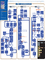
Program the SE2 Inputs and Monitoring Device Outputs (For all configurations: Digital, DeviceNet, Profibus, EtherNet/IP) * Before starting the setup procedure for your SE2 System, refer to the SE2 User’s Manual supplied with your system to: Smart ELECTRODE 2 Mount the SE2 System components (Controller Module, Sensing Module, Electrode). Establish the Air Service Connection. Interconnect all the SE2 System components (Controller Module, Sensing Module, Electrode). Note: In STEPS 2, 3, and 4 that follow, table cells are color Digital Network Communication SE2 Communication Word Display Byte Bit 1 1 0 0 Remote Bypass Channel 1 IN 1 1 1 1 1 Weld Start Input Channel 1 IN 2 1 1 2 2 Remote Learn Channel 1 1 1 3 3 Weld Start Enable Channel 1 1 1 4 4 Schedule Select (bit 1) Channel 1 ** 1 1 5 5 Schedule Select (bit 2) Channel 1 ** Set this bit to 0 for normal operations. Set this bit to 1 to bypass the system. “Pin Returned”, “Weld Proceed”, and “Weld Accept” outputs are forced ON. Note: May allow for a fastener in the incorrect condition to be welded; parts should be 100% inspected if this bit is set to 1. If assigned (for Digital I/O configurations) or enabled (for industrial communications), set this bit to 1 when the Weld Proceed Position is 1, weld pressure has been achieved, and approx. 100 ms before passing weld current. The bit should remain set to 1 for 50 ms or longer and reset to 0 before the next weld. If disabled (Digital I/O) or not enabled (industrial communication), false triggering of PASS/SUSPECT is possible by loading parts or applying weld pressure. Ensure that the weld pin is returned. Select Channel 1 and the schedule to be learned, either manually or using the “Schedule Select” bits below (4, 5, 6, 7) if using DeviceNet, Profibus, or EtherNet/IP. Set this bit to 1 for 50 ms or longer to activate the “Learn” mode. Note: If the selected schedule changes or is turned OFF before the “Learn” process is complete, the “Learn” will be aborted. Set this bit to 1 if using “Weld Start Input”. Binary schedule select (1 – 8 schedules). Before you start the weld, select the schedule desired by setting the corresponding binary bits to 1. Leave the bits at 1 until the weld has been completed. Binary schedule select (1 – 8 schedules). See description in Word 1 / Bit 4. 1 1 6 6 Schedule Select (bit 4) Channel 1 ** Binary schedule select (1 – 8 schedules). See description in Word 1 / Bit 4. 1 1 7 7 Schedule Select (bit 8) Channel 1 ** Disabled 1 2 8 8 Remote Bypass Channel 2 Binary schedule select (1 – 8 schedules). See description in Word 1 / Bit 4. Set this bit to 0 for normal operations. Set this bit to 1 to bypass the system. “Pin Returned”, “Weld Proceed”, and “Weld Accept” outputs are forced ON. Note: May allow a fastener in the incorrect condition to be welded; parts should be 100% inspected if this bit is set to 1. IN 3 1 2 9 9 Weld Start Input Channel 2 IN 4 1 2 10 A Remote Learn Channel 2 1 2 11 B Weld Start Enable Channel 2 1 2 12 C Schedule Select (bit 1) Channel 2 ** 1 1 2 2 13 14 D E Schedule Select (bit 2) Channel 2 ** Schedule Select (bit 4) Channel 2 ** If assigned (for Digital I/O configurations) or enabled (for industrial communications), set this bit to 1 when the Weld Proceed Position is 1, weld pressure has been achieved, and approx. 100 ms before passing weld current. The bit should remain set to 1 for 50 ms or longer and reset to 0 before the next weld. If disabled (Digital I/O) or not enabled (industrial communication), false triggering of PASS/SUSPECT is possible by loading parts or applying weld pressure. Ensure that the weld pin is returned. Select Channel 2 and the schedule to be learned, either manually or using the “Schedule Select” bits below (C, D, E, F) if using DeviceNet, Profibus, or EtherNet/IP. Set this bit to 1 for 50 ms or longer to activate the “Learn” mode. Note: If the selected schedule changes or is turned OFF before the “Learn” process is complete, the “Learn” will be aborted. Set this bit to 1 if using “Weld Start Input”. Binary schedule select (1 – 8 schedules). Before you start the weld, select the schedule desired by setting the corresponding binary bits to 1. Leave the bits at 1 until the weld has been completed. Binary schedule select (1 – 8 schedules). See description in Word 1 / Bit 12. Binary schedule select (1 – 8 schedules). See description in Word 1 / Bit 12. 1 2 15 F Schedule Select (bit 8) Channel 2 ** Binary schedule select (1 – 8 schedules). See description in Word 1 / Bit 12. Wire the SE2 System (all configurations). Establish the network communication connections (for DeviceNet, Profibus, EtherNet/IP configurations only). Power requirements: 24VDC +/-10% ~220mA (with I/O in the sinking mode). PNP, NPN, or Auto-Detect inputs (2 per channel) 24VDC +/-10%. PNP or NPN outputs (4 per channel) 24VDC +/-10% Max. 220 mA. Channel 2 1 1 2 Controller Module Top View 3 4 (a) / (b) Centered on Solutions 2 1 3 4 2 4 3 Channel 1 1 1 2 2 5 3 POWER Power Connector (M12-Micro) Pin Wire Color 1 2 3 4 Brown White Blue Black Grey POWER connector (5-pin male) (a) / (b) Power Connection Channel 2 Channel 1 5 (a) 4 3 OUTPUTS INPUTS Description Function Notes +24VDC Output 5 0 VDC Output 1 Equipment GND +24 VDC (b) Weld Proceed CH 2 (c) 0 VDC (b) Weld Proceed CH 1 (c) Equipment GND (b) Required Required if equipped Required Required Required (c) CH1 OUTPUT connector (4-pin female) Outputs 1 2 3 4 Brown White Blue Black Output 2 Output 3 0 VDC Output 4 Pin Returned CH 1 Learn Active CH 1 (c) 0 VDC Weld Accept CH 1 (c) Required Suggested Suggested CH1 INPUT connector (4-pin male) Inputs 1 2 3 4 Brown White Blue Black Unused Input 1 0 VDC Input 2 Unused Weld Start CH 1 (d) 0 VDC Remote Learn CH 1 (d) N/A Required CH2 OUTPUT connector (4-pin female) Outputs 1 2 3 4 Brown White Blue Black Output 6 Output 7 0 VDC Output 8 Pin Returned CH 2 (c) Learn Active CH 2 (c) 0 VDC Weld Accept CH 2 (c) Required if equipped Suggested if equipped CH2 INPUT connector (4-pin male) Inputs 1 2 3 4 Brown White Blue Black Unused Input 3 0 VDC Input 4 Unused Weld Start CH2 (d) 0 VDC Remote Learn CH 2 (d) N/A Required if equipped DeviceNet Connector Front View 1 2 3 4 5 Profibus Connector Front View 5 1 6 9 Ethernet / IP Front View 1 (a) 4 8 Pin Signal 1 V- 2 CAN_L Notes for STEP 3 and STEP 4: Digital Communication Word Byte 3 SHIELD Cable shield Shield 4 CAN_H CAN high bus line White 5 V+ Positive bus supply voltage 0 Pin Return Channel 1 1 1 1 1 Not Used OUT 1 1 1 2 2 Weld Proceed Channel 1 OUT 4 1 1 3 3 Weld Accept Channel 1 1 1 1 1 4 5 4 5 Not Used Not Used 1 1 6 6 Learn Active Channel 1 1 1 1 2 7 8 7 8 1 2 9 9 1 2 10 A 1 2 11 B 1 1 1 1 2 2 2 2 12 13 14 15 C D E F 2 1 0 0 OUT 3 OUT 6 2 1 1 1 OUT 5 2 1 2 2 OUT 8 2 1 3 3 2 2 1 1 4 5 4 5 2 1 6 6 2 2 2 7 8 7 8 2 2 9 9 2 2 10 A 2 2 11 B 2 2 2 2 2 2 2 2 12 13 14 15 C D E F 3 1 0 0 3 1 1 1 3 3 3 3 3 3 1 1 1 1 1 1 2 3 4 5 6 7 2 3 4 5 6 7 3 2 8 8 3 2 9 9 3 3 3 3 3 3 2 2 2 2 2 2 10 11 12 13 14 15 A B C D E F Red Pin Signal Description 1, 2, 7, 9 3 4 5 6 8 B Line RTS GND Bus +5V Bus Output A Line Housing Cable Shield Unused Positive RxD/TxD, RS485 level Request to send Ground (isolated) +5 V termination power (isolated) Negative RxD/TxD, RS485 level Internally connected to the Communication Module protective earth via cable shield filters according to the PROFIBUS standard. Pin Wire Color Name 1 2 3 4 5 6 7 8 White Green Green White Orange Blue White Blue Orange White Brown Brown TX+ / RX+ TX- / RXRX+ / TX+ Unused Unused RX- / TXUnused Unused Important: If power connector is 4 pin, the controller case needs to have an equipment GND attached. (b) For network communication (DeviceNet, Profibus, EtherNet/IP), only the power connection is required. Pins 1, 3, and 5 are used. (c) By changing the setup in the Advanced menu, you can select NPN output function (see Main Menu > Advanced > Digital Outputs > Output Type). (d) There are two inputs per channel that are configurable, with three options to choose from. They can be assigned to Remote Learn, Remote Bypass, or Weld Start under the Main Menu > Advanced > Digital Inputs > Input Assignment. Description 0 Wire Color Blue SE2 Display 1 Suggested if equipped CAN low bus line Bit 1 Suggested if equipped Black 2 0 1 1 0 0 1 1 0 4 0 0 0 1 1 1 1 0 8 0 0 0 0 0 0 0 1 Program the SE2 Outputs and Monitoring Device Inputs (For all configurations: Digital, DeviceNet, Profibus, EtherNet/IP) * Network Communic. OUT 2 Negative bus supply voltage 1 1 0 1 0 1 0 1 0 * DeviceNet, Profibus, EtherNet/IP – 6 bytes inputs, 2 bytes outputs. Communication Rate: Auto Baud. ** Refer to the “Binary Schedule Select” table in the upper right-hand corner of this page. Suggested Description Monitoring Device Output Programming Considerations Disabled coordinated. White cells are applicable to all configurations (Digital I/O, DeviceNet, Profibus, EtherNet/IP). Description BINARY SCHEDULE SELECT Binary Bit # Schedule 1 Schedule 2 Schedule 3 Schedule 4 Schedule 5 Schedule 6 Schedule 7 Schedule 8 Ask us about the SE2 View Software: • Indicates trends for Weld Proceed and Set-Down. • Captures information for all eight schedules. • Can be used to back up schedules, OEM and Advanced Parameters. Install the SE2 System OUT 7 Monitoring Device Input Programming Considerations Bit is set to 1 when the weld pin is at returned position (fully extended). Suggest generating a fault if the input is 0 (for one second) when the upper electrode is returned and the welded part has been removed or an un-welded part is present and binding on the pin. Bit is set to 1 when the fastener is in the correct orientation and the projections are against the stamping. Bit is reset to 0 when the pin is returned. Suggest generating a fault if you advance the upper electrode and the input is 0 for 1.5 seconds. Bit is set to 1 when the weld performed matches the learned schedule (comparing “Set-Down” and “Set-Down Sigma”). Bit is reset to 0 after approx. 0.5 seconds. Generate a user fault if the weld is completed and the input is 0. See “Set-Down Alarm” and “Set-Down Sigma Alarm” below. Bit is set to 1 when the SE2 is in “Learn” mode. The input will reset to 0 after a successful learn, if the schedule selection is changed or turned OFF before “Learn” is complete, or when power is cycled. Suggest generating a fault if the input is 1 after “Max. Learn Welds” number is reached in “Learn Setup” (default is 5). See Main Menu > Advanced > Learn Setup > Max. Learn Welds. Selected Schedule not Learned Channel 1 Bit default status is 0; it is set to 1 to inform when the selected schedule has not been learned. Not Used Bit default status is 0; it is set to 1 if “Set-Down Sigma” is ON in the schedule and the “Max. Consecutive Fails” value is reached Set-Down Sigma Alarm Channel 1 (default is 3). See Main Menu > Advanced > Setdown Sigma > Max. Consecutive Fails. For specific information, generate a user message. Not Used Bit default status is 0. If this bit is 1, signifies that the weld was not set-down relative to the learned schedule and the weld is Set-Down Alarm Channel 1 suspect. For specific information, generate a user message. Schedule Report (bit 1) Channel 1 ** Schedule select handshake information. These bits should correspond to the currently selected SE2 schedule for channel 1. Schedule Report (bit 2) Channel 1 ** Schedule select handshake information. These bits should correspond to the currently selected SE2 schedule for channel 1. Schedule Report (bit 4) Channel 1 ** Schedule select handshake information. These bits should correspond to the currently selected SE2 schedule for channel 1. Schedule Report (bit 8) Channel 1 ** Schedule select handshake information. These bits should correspond to the currently selected SE2 schedule for channel 1. Bit is set to 1 when the weld pin is at returned position (fully extended). Suggest generating a fault if the input is 0 (for one second) Pin Return Channel 2 when the upper electrode is returned and the welded part has been removed or an un-welded part is present and binding on the pin. Not Used Bit is set to 1 when the fastener is in the correct orientation and the projections are against the stamping. Bit is reset to 0 when the Weld Proceed Channel 2 pin is returned. Suggest generating a fault if you advance the upper electrode and the input is 0 for 1.5 seconds. Bit is set to 1 when the weld performed matches the learned schedule (comparing “Set-Down” and “Set-Down Sigma”). Bit is reset Weld Accept Channel 2 to 0 after approx. 0.5 seconds. Generate a user fault if the weld is completed and the input is 0. See “Set-Down Alarm” and “Set-Down Sigma Alarm” below. Not Used Not Used Bit is set to 1 when the SE2 is in “Learn” mode. The input will reset to 0 after a successful learn, if the schedule selection is changed Learn Active Channel 2 or turned OFF before “Learn” is complete, or when power is cycled. Suggest generating a fault if the input is 1 after “Max. Learn Welds” number is reached in “Learn Setup” (default is 5). See Main Menu > Advanced > Learn Setup > Max. Learn Welds. Selected Schedule not Learned Channel 2 Bit default status is 0; it is set to 1 to inform when the selected schedule has not been learned. Not Used Bit default status is 0; it is set to 1 if “Set-Down Sigma” is ON in the schedule and the “Max. Consecutive Fails” value is reached Set-Down Sigma Alarm Channel 2 (default is 3). See Main Menu > Advanced > Setdown Sigma > Max. Consecutive Fails. For specific information, generate a user message. Not Used Bit default status is 0. If this bit is 1, signifies that the weld was not set-down relative to the learned schedule and the weld is Set-Down Alarm Channel 2 suspect. For specific information, generate a user message. Schedule Report (bit 1) Channel 2 ** Schedule select handshake information. These bits should correspond to the currently selected SE2 schedule for channel 2. Schedule Report (bit 2) Channel 2 ** Schedule select handshake information. These bits should correspond to the currently selected SE2 schedule for channel 2. Schedule Report (bit 4) Channel 2 ** Schedule select handshake information. These bits should correspond to the currently selected SE2 schedule for channel 2. Schedule Report (bit 8) Channel 2 ** Schedule select handshake information. These bits should correspond to the currently selected SE2 schedule for channel 2. Bit default status is 0; it is set to 1 when the “Pin Return” and “Weld Proceed” have been bypassed using the controller interface. PR & WP Internally Bypassed Channel 1 Note: May allow for a fastener in the incorrect condition to be welded; parts should be 100% inspected if this output is ON. Bit default status is 0; it is set to 1 when the “Weld Accept” has been bypassed using the controller interface. This ignores the final WA Internally Bypassed Channel 1 welded position of the fastener. Not Used Not Used Not Used Not Used Not Used Not Used Bit default status is 0; it is set to 1 when the “Pin Return” and “Weld Proceed” have been bypassed using the controller interface. PR & WP Internally Bypassed Channel 2 Note: May allow for a fastener in the incorrect condition to be welded; parts should be 100% inspected if this output is ON. Bit default status is 0; it is set to 1 when the “Weld Accept” has been bypassed using the controller interface. This ignores the final WA Internally Bypassed Channel 2 welded position of the fastener. Not Used Not Used Not Used Not Used Not Used Not Used SE2 System is protected by U.S. patents # 6,576,859; 6,750,419; 6,906,279; 7,282,664; 7,564,005 with other U.S. and foreign patents pending. GENERATION II SOLUTIONS CenterLine (Windsor) Limited 655 Morton Dr., Windsor, ON, N9J 3T9 P.O. Box 321187, Detroit, MI 48232-1187 • Toll Free (800) 268-8330 • Can. (519) 734-8330 • U.S. (313) 961-3731 • Fax (519) 734-2006 Email: [email protected] Continue on the reverse GENERATION II SOLUTIONS www.cntrline.com Copyright © 2009, CenterLine (Windsor) Limited , SE2-QS-PR-1.0.2-10-09 CenterLine (Windsor) Limited Displayed Channel Number 655 Morton Dr., Windsor, ON N9J 3T9 P.O. Box 321187, Detroit, MI 48232-1187 Toll Free: (800) 268-8330 Canada: (519) 734-8330 U.S.: (313) 961-3731 Fax: (519) 734-2006 Email: [email protected] www.cntrline.com Process Monitoring LEDs Button Number Assignment Configuration Sensor Calibration Learn START START Channel Select Button Previous Menu Button Navigation Buttons START Select / Enter Button Verify weld quality specifications prior to learning weld schedules. HELP HELP • Channel Select Button - Toggles between Channel 1 and 2, if equipped. (See “Displayed Channel Number” in the picture above). HELP • Previous Menu Button - Takes you back to the previous menu or to the Main Menu. • Navigation Buttons - Navigate up and down the list of available menus and parameters. This screen is displayed for dual-channel configurations. For single-channel configurations, only “Learn Channel 1” will be visible. Or Other Options • Select / Enter Button - Press this button to select the highlighted selection. YES Highlight DONE, then press • Button Number Assignment - The numeric value assigned to each button is printed in the lower right-hand corner of the button. The system automatically switches between regular use of buttons and their numeric assigned values (for password entry only). Digital I/O . NEXT If calibrating Channel 2, the number changes to 2 . DeviceNet Profibus EtherNet/IP Through logic, select the desired schedule for the channel, then pulse the remote learn bit to activate “Learn” mode. (Refer to STEP 3 on the other page). INFO NEXT NEXT NEXT Activates “Learn” mode and resets the counter. INFO Caution ! YES YES NEXT Digital I/O DeviceNet, Profibus, or EtherNet ? Perform welds. Typically 1 or 2 out of 5 welds are required to learn. INFO If the Weld Start Input is disabled (Digital I/O) or not enabled (Industrial Communication), false triggering of PASS/SUSPECT is possible by loading parts or applying weld pressure. NO NO Close gun or manually push pin using the fastener. Hold it in that position. Press . Note orientation of projections on fastener. Perform welds. Typically, 1 or 2 out of 5 welds are required to learn. Activates “Learn” mode and resets the counter. NO YES YES Successful Learn ? Release pin. Is 0.4 V < PRP voltage < 1.5 V ? YES NO NO YES NO If the learn sequence of a previously learned schedule fails, the previous schedule is reloaded. NEXT NEXT Other Options Run Depress pin to SPAN position. Is NO Select Schedule Edit YES YES Delete Learn Setup YES NO YES (Sets Learn Setup minimum learn welds to 1) Ch/Bypass Digital Inputs Debug Screen NO (Sets Learn Setup minimum learn welds to 2 (Default)) Weld Pro. Pos (%): Set-Down (%): Set-Down Sigma: PRP Tol. Ratio: WPP Stable Time (ms): WSI Time Marker (ms): No Presets Min. Learn Welds: Max. Learn Welds: Learn Tolerance (%): Channel: PR & WP Bypass: Weld Acc. Bypass: . NEXT Setdown Sigma Password Miscellaneous END Learn Sensor Counters I/O Status END * If equipped Input Assignment Input Type Advanced Digital Outputs Highlight DONE, then press END No Presets (–) ↓ ↓ 25 45 25 35 OFF 3 50 0 2 5 1 CH1 ↓ CH2 * ↓ ON OFF OFF ON OFF OFF CH1 / CH2* ↓ ↓ NEXT Other Option Default Value (+) Schedules DeviceNet, Profibus, or EtherNet ? Parameter No Presets NO Digital I/O NO Submenu Activate ? END SE2 Default Parameters YES Menu NEXT DeviceNet, Profibus, or EtherNet/IP NO Digital I/O ? Output Assignment Remote Learn: Remote Bypass: Weld Start: Auto-Detect Pin Return: Weld Proceed: Weld Accept: Learn Active: PNP Input 2 / 4 Disabled Input 1 / 3 Output Output Output Output 2 1 4 3 / / / / 6 5 8 7 Output Type Sigma Factor: 3.0 Minimum Limit (%): 1.0 Max. Consecutive Fails: 3 Idle Reset Time (mins.): 60 Minimum No. of Samples: 8 Default “11111” Language English, DeviceNet, Profibus address is 63 Password to Clear Counters ON No Presets Setup Wizard No Presets Power Level: 10, Current is read from the Sensing Module Board No Presets No Presets