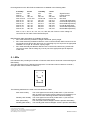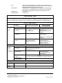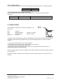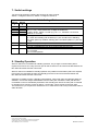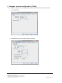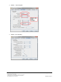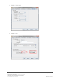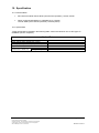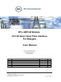
1
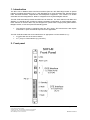
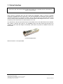
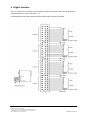
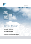
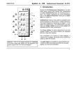
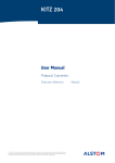
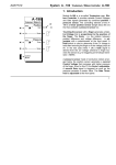
RFL-SHFI-M Module C37.94 Short Haul Fibre Interface For Milegate User Manual RFL Communications plc www.rflcomms.co.uk 01249 446500 Issue A Amendment Details Initial Issue RFL-SHFI-M Module User Manual © RFL Communications plc 2014 All rights reserved. The information contained in this document is the property of RFL Communications plc and is supplied without liability for errors or omissions. Date of Issue 27 Aug 14 By PH Page 1 of 13 Issue A 27.08.14 Contents 1. Introduction ............................................................................................................................... 3 2. Front panel ................................................................................................................................ 3 3. Optical Interface........................................................................................................................ 4 4. Digital Interface ......................................................................................................................... 5 5. LEDs ......................................................................................................................................... 6 6. Alarm output ............................................................................................................................. 8 7. Switch settings .......................................................................................................................... 9 8. Standby Operation .................................................................................................................... 9 9. Milegate channel configuration (TUDA).................................................................................. 10 10. Specification .............................................................................Error! Bookmark not defined. RFL-SHFI-M Module User Manual © RFL Communications plc 2014 All rights reserved. The information contained in this document is the property of RFL Communications plc and is supplied without liability for errors or omissions. Page 2 of 13 Issue A 27.08.14 1. Introduction The RFL C37.94 Module Short Haul Fibre Interface (Part No. RFL-SHFI-M) provides an optical interface compliant with IEEE C37.94 “IEE Standard for N Times 64 Kilobit Per Second Optical Fibre Interfaces between Teleprotection and Multiplexer Equipment”. The module is a double extended eurocard designed as a ‘blade’ to integrate into a Keymile Milegate chassis. The RFL-SHFI-M module provides two IEEE C37.94 channels. For each channel, both Main and Standby V11 interfaces are provided to support redundant configuration of communication paths. Each channel on the RFL-SHFI may be configured to operate with a single (main) path between Milegate nodes, or with dual (main and standby) paths. The SHFI-M module is equipped with two SFP cages; SFP transceivers with duplex multimode LC ports are fitted as required for the application. The RFL-SHFI-M module has to be interfaced to an appropriate V11/X24 interface, e.g.: A TUDA card card in the same chassis. rd A 3 party V11/X24 interface (e.g. BT NTU). 2. Front panel RFL-SHFI-M Module User Manual © RFL Communications plc 2014 All rights reserved. The information contained in this document is the property of RFL Communications plc and is supplied without liability for errors or omissions. Page 3 of 13 Issue A 27.08.14 3. Optical Interface Note: Fibre optic transceivers fitted to SHFI-M modules are compatible with the standards for Class 1 laser products Each channel is equipped with one SFP (small form pluggable) cages, to accept a suitable multimode 1000Base-SX SFP transceiver. The SFP transceivers are equipped with duplex LC connectors (62.5/125 µm or 50/125 µm fibre), and as with the SHFI, the connectors are angled down to allow the fibre patchleads to be accommodated behind the Milegate front cover. It is not necessary to fit a transceiver to a channel that is not in use. Any transceiver used with the SHFI-M has to be suitable for the low data rates that are utilised. RFL supply a specific SFP (part no. CT-0155NSP) which has been tested and proved to be suitable over the data rate ranges encountered; other SFPs may also be suitable but have not been tested. C37.94 Compliant SFP Refer to Section 11 for optical data. RFL-SHFI-M Module User Manual © RFL Communications plc 2014 All rights reserved. The information contained in this document is the property of RFL Communications plc and is supplied without liability for errors or omissions. Page 4 of 13 Issue A 27.08.14 4. Digital Interface The V11 / X24 ports on the RFL C37.94 SHFI-M module are identical to the ports on the Keymile TUDA card DTE V11 / X24 (channels 1 – 4). Pin assignments on the RFL SHFI-M and the TUDA 36 pin connector as follows: RFL-SHFI-M Module User Manual © RFL Communications plc 2014 All rights reserved. The information contained in this document is the property of RFL Communications plc and is supplied without liability for errors or omissions. Page 5 of 13 Issue A 27.08.14 Pin assignments on the RFL-SHFI-M module are as detailed in the following table: 2 standby Pins 2a Pins 8a Pins 2b, 2c Pins 3a to 7a Pins 3b, 3c Pins 4b, 4c Pins 5b, 5c Pins 6b, 6c Pins 7b, 7c Pins 8b, 8c 2 main 10a 16a 10b, 10c 11a to 15a 11b, 11c 12b, 12c 13b, 13c 14b, 14c 15b, 15c 16b, 16c 1 standby 18a 24a 18b, 18c 19a to 23a 19b, 19c 20b, 20c 21b, 21c 22b, 22c 23b, 23c 24b, 24c 1 main 26a 32a 26b, 26c 27a to 31a 27b, 27c 28b, 28c 29b, 29c 30b, 30c 31b, 31c 32b, 32c Signal Ground Frame Ground Not used Not used TA and TB respectively CA and CB respectively RA and RB respectively IA and IB respectively SA and SB respectively BA and BB respectively Pins 1a, 1b, 1c, 9a, 9c, 9c, 17a, 17b, 17c, 25a, 25b, 25c Ground. Note: mating C/4 connectors do not make contact with these pins. Manufactured cable assemblies are available as follows: RFL Cable Assembly 05-0805-51 Single ended lead; specify length. RFL Cable Assembly 05-0805-52 Generic cross-connect lead with SHFI connector at one end and D15 male plug at the other end, for connecting any C37.94 port to an appropriate standard X.21 15 pin ‘D’ connector; specify length. RFL cable assembly 05-0805-53 UMUX Cross-connect lead; 700mm long overall with connector at each end for linking any C37.94 port to the appropriate port an adjacent TUDA card. 5. LEDs LED indicators are providing an indication of channel status and to assist with commissioning and fault-finding. The LEDs are laid out in the following arrangement. The left hand column relates to channel 1; the right hand column relates to channel 2. 1 2 DCE STATUS The following definitions are used in the LED Definition Table: Main clock healthy Standby clock healthy Main path healthy Standby path healthy The clock signal from the DCE (TUDA X24/V.11) for the main path is present and phase locked (a path may be temporarily out of phase lock when switching between main and standby). The clock signal from the DCE (TUDA X24/V.11) for the main path is present and phase locked. The main path between Milegate nodes is present and healthy. The standby path between Milegate nodes is present and healthy RFL-SHFI-M Module User Manual © RFL Communications plc 2014 All rights reserved. The information contained in this document is the property of RFL Communications plc and is supplied without liability for errors or omissions. Page 6 of 13 Issue A 27.08.14 Sync Yellow alarm Flashing fast Flashing slowly The channel is said to be in sync if the DTE is visible (i.e. the SHFI-M is receiving data from the DTE on the C37.94 optical port although the data rate need not be correct). Remote alarm. The equipment at the opposite end of the link is out of sync (i.e. transmitting but not receiving). For the SHFI-M this relates to equipment on the local C37.94 fibre link only. 2 flashes in 1s 1 flash in 2s LED Definition Table Note: If a channel is not in use, setting that channel to ‘disabled’ (see Switch Settings Table) will force both LEDs for that channel to ‘off’. This table is therefore applicable to enabled paths only. Channel 1 LED Indicators LED status Channel 1 DCE Main and standby path enabled Hardware fault on RFL-SHFI-M Main clock healthy Main and standby clocks and healthy, and Main path healthy Main and standby paths healthy Not applicable Either main or standby clock missing or Either main or standby path missing Main clock missing, or Both main and standby Main path missing, or clocks missing, or Milegate config error Both main and standby paths missing, or Milegate config error Main path only enabled Off Green steady = Healthy Green flashing slowly = Warning Green flashing fast = Alarm Channel 1 Status Off Green steady = Healthy (in order of precedence) Green flashing slowly = Information Green flashing fast = Alarm DTE out of sync In sync Correct data rate configuration. Main path is in use Not applicable In sync and correct data rate configuration. Comms has switched to standby path In sync Incorrect data rate configuration (see switch settings) Yellow steady = Remote alarm Yellow Alarm Channel 2 LED Indicators Channel 2 DCE Channel 2 Status As channel 1 As channel 1 As channel 1 As channel 1 RFL-SHFI-M Module User Manual © RFL Communications plc 2014 All rights reserved. The information contained in this document is the property of RFL Communications plc and is supplied without liability for errors or omissions. Page 7 of 13 Issue A 27.08.14 Channel Healthy Status: For an enabled channel (with or without standby path), the following state = completely healthy: DCE LED Status LED Solid Green Solid Green Channel Operational but with warnings status: For an enabled channel with standby, the following states = the channel operational with warnings: DCE LED Status LED Slow Flash Green Slow Flash Green Either Main or Standby Clock has been lost Comms has switched to Standby Path 6. Alarm output One voltage free changeover contact is presented on an RJ11 jack. Pin 1 Pin 2 Pin 3 Pins 4 to 6 Common Normally Closed Normally Open Not used Pin1 (closed = no alarm) (closed = alarm) The alarm relay will operate if any alarm is displayed on the RFL-SHFI-M module (see section 5). In summary the alarm relay operates when any of the following events occur on an enabled channel: 1. One or both clocks missing on V11 DCE interface. 2. Receiving Yellow Alarm (i.e. alarm from remote end of DTE link) 3. Receive fibre out of sync with DTE equipment 4. Mismatch in data rate setting (Number of Time slots used) between local and remote, or between DCE and RFL-SHFI-M module. Ensure unused channels are set to ‘disabled’ (see Switch settings); this will inhibit alarm operation for that channel. Note that the alarm contact will close during boot-up and synchronisation. This could be up to 5 minutes. RFL-SHFI-M Module User Manual © RFL Communications plc 2014 All rights reserved. The information contained in this document is the property of RFL Communications plc and is supplied without liability for errors or omissions. Page 8 of 13 Issue A 27.08.14 7. Switch settings Two 8 way Dip switches configure the functions for each channel. Switch 1 configures channel 1; Switch 4 configures channel 2. Switch Settings Table Switch 1 Ch 1 1–1 1–2 1–3 1–4 1–5 Switch 4 Ch 2 4–1 4–2 4–3 4–4 4–5 1–6 1–7 4–6 4–7 1–8 4–8 Function 0000 = channel disabled (use this setting if port not used) 0001 to 1100, channel data rate, multiple of 64kbits/sec, Coded in binary, switch 1 is LSB. (e.g. for n = 1, set switch 1 to On and switches 2 – 4 to Off) Standby path switch: On = Main and standby path enabled (V11 port can fall back to Standby) Off = Main path only enabled; standby path not enabled (Main V11 port only in use) On = Local Loop on fibre port On = Disable fibre port when received signal data is low Off = Do not disable fibre port when received signal level is low Test mode switch: On = not used Off = normal operation 8. Standby Operation When a channel is not enabled for standby operation, only a single communication path is required from end to end. Only the main port for that channel is to be interconnected between the RFL-SHFI-M module and the TUDA card. When a channel is enabled for standby operation two parallel communication paths are required from end to end, and both the main and standby ports are to be interconnected between the RFL-SHFI-M module and the TUDA card. Operation of standby function. (Standby path enabled). When both main and standby paths are available, comms are always transmitted across the main path. Should the main path become unavailable comms is immediately switched to the standby path. When the main path is restored to operation for a period in excess of approx. 15 seconds, comms reverts to the main path. The switch time (i.e. the period for which there is no valid comms end to end) is less than 50ms in either direction. RFL-SHFI-M Module User Manual © RFL Communications plc 2014 All rights reserved. The information contained in this document is the property of RFL Communications plc and is supplied without liability for errors or omissions. Page 9 of 13 Issue A 27.08.14 9. Milegate channel configuration (TUDA) This configuration applies to each channel that is interconnected to the RFL-SHFI-M module. 1. General Settings: 2. Signal Structure can be left as per default, as below: RFL-SHFI-M Module User Manual Page 10 of 13 © RFL Communications plc 2014 All rights reserved. The information contained in this document is the property of RFL Communications plc and is supplied without liability for errors or omissions. Issue A 27.08.14 3. Details – Control Signals 4. Details – Error Handling RFL-SHFI-M Module User Manual Page 11 of 13 © RFL Communications plc 2014 All rights reserved. The information contained in this document is the property of RFL Communications plc and is supplied without liability for errors or omissions. Issue A 27.08.14 5. Details – Test Loops 6. Details – CTP RFL-SHFI-M Module User Manual Page 12 of 13 © RFL Communications plc 2014 All rights reserved. The information contained in this document is the property of RFL Communications plc and is supplied without liability for errors or omissions. Issue A 27.08.14 10. Specification 10.1 Electrical Data RFL-SHFI-M module load at 48Vdc (dual channel operation) = 53mA; 2.54W When configured standalone in a Milegate rack + FANU6 Load at 48Vdc (dual channel operation) = 200mA (9.6W) 10.2 Optical Data Typical optical data is detailed in the following table. Values are based on the on SFP type CT0155NSP (C37.94 compliant). Optical Data SHFI-M Peak optical power output (min / max) Average optical power output (min / max) Optical sensitivity Recommended max Using 62.5/125µm transmission distances Using 50/125µm -19dBm / -11dBm -32dBm 300m 550m RFL-SHFI-M Module User Manual Page 13 of 13 © RFL Communications plc 2014 All rights reserved. The information contained in this document is the property of RFL Communications plc and is supplied without liability for errors or omissions. Issue A 27.08.14