1
POWERJECTION III
™
Installation Instructions & User Manual
70020 70021 70026 70027 70028 70029 Kits
70027 Kit Shown. Other kits will
vary in appearance and contents
Professional Products
Powerjection III is
protected by US Patent:
#7,735,475
2205 El Segundo Boulevard
Hawthorne, CA 90250
Tech: 323-779-2020
www.professional-products.com
www.professional-products.com/forum
Copyright 2012 Professional Products
POWERJECTION III USER MANUAL TABLE OF CONTENTS
Introduction
Important Information — Please Read
System Components and Contents
Common Terms Used in This Manual
Tools, Equipment, and Fittings
Wideband Oxygen Sensor Installation
Fuel System Installation and Requirements
Fuel System Plumbing
Installing the Throttle Body
Cranking and Charging Requirements
Wiring Harness Installation
Distributor and Spark Setup
Dashboard Software Installation
Running the Dashboard Software
Idle Adjustment Procedure
Dashboard—Menu Functions
Dashboard—Edit Menu
Learn Fuel, Target Air/Fuel, and Fuel Table
2
2
3
3
4
4
4
5
6
6
7
7
8
8
9
10
11
11
Learn Cell Protect, Accel / Decel Fueling
Crank/Cold Engine, IAC Control
Spark Table
Main Setup
Fuel Wizard
Calibrate TPS
Spark Setup
Real Time ECU Data
Histogram
Loading / Saving a Calibration
Calibration for Startup
Adjusting the Fuel Wizard
Adjusting the Fuel Wizard Sliders
Spark Setup
Ignition Pickup Input Delay
ECU Control / Test Menu
Troubleshooting Guide
12
13
14
14
15
15
16
16
17
17
18
18
19
19
19
19
20
INTRODUCTION
Thank you for your purchase of the Professional Products Powerjection III Fuel Injection System. In the manual we will outline the Powerjection III installation and use of the Stage III Dashboard software. If during installation you have any questions
about the procedure or software, please call our Technical Support Line at 323-779-2020. The technical staff is knowledgeable
and fully equipped to assist you with every step of your experience.
IMPORTANT INFORMATION — PLEASE READ
The Powerjection III throttle body fits common square-bore
carburetor applications directly or on spread bore manifolds
with adapter #52111. The throttle body linkage is the same
as a 4150 style carburetor. Therefore, no modification to the
throttle or transmission linkage should be necessary.
The starting and charging system must be in good condition
and able to support the additional load of the EFI system.
Low cranking voltage will create start-up issues. Make sure
you have adequate cranking voltage and make all necessary
repairs before installing the Powerjection III system.
The Powerjection III EFI comes with a base calibration in- The 70120-70127 EFI kits are the same as the 70020-70027
stalled for an engine of approximately 340-360 CID and/or except for the 1200 CFM Throttle body and the #96 lb/hr
about 300 horsepower. If your engine is in this range there injector flow rate injectors.
should be minimal laptop tuning needed.
WARNING! – Never use Teflon tape on
Any A/N fitting or anywhere else in the fuel
system. Teflon tape can break free, clog
injectors, and will not be covered by warranty. Use Loctite #246 sealant for pipe
thread connections.
The included CD will install the Dashboard software on your
PC to interface with the ECU and will also install several
base calibrations for other engine combinations. The software is also downloadable from www.professionalproducts.com/forum
The Powerjection EFI will not correct a damaged, improperly
running, or poor mechanical condition engine. The Powerjection III system will only optimize the current condition of your
engine when calibrated properly.
2
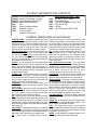
SYSTEM COMPONENTS AND CONTENTS
70020-04
70020-05
70020-09
70320-05
70331
71200
71240
71250
USB-to-Serial Adapter and Serial Cable
Gasket kit -Throttle body, Air cleaner
Stage III Dashboard Software CD
Vehicle Wiring Sub-harness
ECU
Coolant Temperature Sensor
Wideband O² sensor
O² sensor bung kit
Installation / User manual
10409
11113
70042
70151
70160
70035
Items Included in Kit 70026 — 70029
Fuel Inlet Kit (70028 - 70029)
Fuel Pressure Gauge
Fuel Inlet With Regulator (70026 - 70027)
Fuel Pump 220 LPH
Fuel Filter
Fuel On Demand kit (70028 - 70029)
COMMON TERMS USED IN THIS MANUAL
ADAPTIVE LEARN – This feature was pioneered by Professional Products for aftermarket EFI systems. By using a wide
band oxygen sensor, the ECU can determine the actual Air
Fuel Ratio of the engine. The ECU makes necessary adjustments to maintain the Target Air Fuel Ratio. These adjustments are occurring constantly while the engine is running.
AIR FUEL RATIO (AFR) – The mixture of air and fuel to promote combustion. A ―Rich‖ AFR (e.g. 12.5) is a value less than
14.7 AFR for gasoline and ―Lean‖ is an AFR greater than 14.7
(e.g. 15.5). Rich or Lean can also refer to the actual AFR relative to your Target Air Fuel Ratio. Other fuels like Ethanol have
stoichiometric Air Fuel Ratio of 9.0:1.
ALPHA-N —A mode that allows fuel to be calculated based
on throttle position and RPM. Useful on engines with very high
duration and overlap camshafts. Can also be used in a
boosted application where the fuel system adds additional fuel
per pound of boost based on the ECU mounted MAP sensor
to determine boost pressure.
CLOSED LOOP – Closed loop allows the ECU to make short
term adjustments to the fueling. This feature combined with
Learn Fuel allows the ECU to make short term (Closed Loop),
quick, non-saved changes and long term saved (Learn Fuel)
changes to the engine’s fueling requirements.
DASHBOARD - This is your ECU interface software. It provides you with the ability to infinitely tune your system to your
engine’s needs.
DATA LOGGING – Allows you to record all the data the ECU
can produce while you drive your vehicle and then will allow
you to see a timeline of what has actually occurred during
vehicle operation. Laptop connection is required.
ECU - engine control unit - the computer mounted on the throttle body that controls the fueling, spark and idle system. Uses
Water temp, RPM (From tach input or 2-wire), MAP, TPS, and
wideband AFR to determine the fueling needs of the engine.
Will recalculate the engines fueling needs based on feedback
from the o2 sensor.
FUEL WIZARD - This Dashboard tool allows you to customize
the base fuel map for your engine. It takes into account engine
torque and your engine’s torque curve to generate a basic fuel
table that the Learn Fuel will alter to your engines needs.
IAC — Idle Air Control is a stepper motor that moves a
plunger in and out of the IAC orifice which allows air to pass
around the throttle blades to control idle speed. The IAC orifice
has a limited range of airflow so the throttle blade position
passes the majority of the engine’s idle airflow at idle. The IAC
trims the throttle bypass airflow so that RPM can be controlled
without having to change the throttle angle for cold starts.
kPa – Kilopascal is a metric measurement of pressure. 10-100
kilopascals equal the 26.5‖-0‖ vacuum range while values
greater than 100 indicate boost. The Dashboard software
shows the kPa reading as the dominant number that references to tables, directly below that reading is inches of vacuum or PSI (in boost).
MAP / Manifold Absolute Pressure – This is the absolute
(not gauge) pressure inside your intake manifold measured in
kilopascals (kPa). This reading takes into account atmospheric
pressure and altitude. MAP is one of the main inputs to determine air density and thus air flow into your engine.
A map (small case) can refer to your fuel ―map‖ or chart.
PULSE WIDTH - This refers to the length of time that an injector nozzle is open and injecting fuel into the airstream. It is
measured in either milliseconds (ms) or microseconds (us)
SPARK ADVANCE —The position in crankshaft degrees before Top Dead Center that the spark plug is ignited to produce
the most power. The proper application of spark timing will
give the engine the optimal power by allowing the maximum
cylinder pressure to be placed on the piston top at approximately 10-17 degrees after Top Dead Center. Too much advance will cause pre-ignition or ―pinging‖ and too little timing
will cause overheating of the exhaust from late ignition.
TOP DEAD CENTER — Position of the piston in relationship
to the crankshaft where the piston is at it’s highest point in the
engine block.
TARGET A/F – Commands the Target Air Fuel Ratio that the
ECU is to achieve at specific RPM and MAP ranges. The Target A/F changes with load (MAP) and RPM
TPS% — The Throttle Position Sensor is used to determine
load. It also determines acceleration enrichment by measuring
the rate at which the throttle is opened and applying extra fuel
in proportion to the opening rate.
WATER – Coolant temperature in degrees Fahrenheit. Determines coolant based engine operation parameters.
3
TOOLS, EQUIPMENT, AND FITTINGS
The only specialized tools required are for fuel tank modifications or welding equipment should you decide to weld on the
02 bung kit. A selection of hand tools, a wire stripper and crimper, soldering iron, solder, wire terminals, and heat shrink
tubing should be the main requirements.
Determine all wire terminals and lengths
before you begin so that your installation
goes smoothly. If you have power brakes,
a PCV system, and/or a transmission vac1/4-NPT x -06AN
#15239 (blue)
uum modulator you will need the appropri#16239 (black)
ate vacuum splice or "T" to connect to the
3/8-inch vacuum port at the rear of the
throttle body or to the intake manifold. The
fuel pump and EFI inline filter require male
1/4-NPT fittings. The feed line to the fuel 1/4-NPT x 3/8 hose
pump must be 3/8-inch hose or - 06AN barb fitting #10244
minimum. All pressure-side fuel lines to the
throttle body are required to be fuel injection rated (working
pressure is 45 PSI). We highly recommend the use of steel
lines in good condition or AN style fittings and braided hose for
all applications. See Powerflow fuel line kits 70107 (return
style) or 70108 (returnless) for a complete fuel line kit.
#17239 (polished)
WIDEBAND OXYGEN SENSOR INSTALLATION
We suggest installing the o2 sensor bung kit first so if exhaust pipe and start the wormnecessary the vehicle can be driven to a muffler shop gears. Place the gasket over the
5/8‖ hole and place the stainless
before disassembly.
steel bung over the gasket.
Position the O2 sensor in the col- Tighten the hose clamps to se- #71250 O2 Bung Kit – Stainless
lector on the number one bank of cure. Optionally you can weld Can be welded if desired
cylinders or in the extension pipe the bung in place. Keep all wiring away from sharp edges and
on a stock exhaust. Mark the pipe hot exhaust. Plug the harness cable from the throttle body into
between 9 and 3 o’clock. This the cable from the Oxygen Sensor. Using cable or zip ties,
prevents condensation from collecting in and destroying the keep harness away from exhaust or moving parts. Do not
sensor. Drill a 5/8 inch hole. Place supplied hose clamps on drive with the o2 disconnected from the ECU.
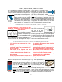
FUEL SYSTEM INSTALLATION AND REQUIREMENTS
All fuel lines from tank to pump must be 3/8 inch
minimum.
All fuel line from the pump to the throttle body
should be 3/8” or -06 AN and pressure rated for fuel
injection use (45 PSI).
Always mount the fuel pump away from heat
sources and/or be heat shielded to prevent damage
to the pump and cavitation issues caused by heat.
Cavitation is like severe engine detonation and will
destroy the pump.
The fuel pump must be mounted in a position at or
below the fuel level and as close as possible to the
Install a fuel line from the fuel tank outlet to the fuel pump
inlet. Using the stock sock/screen type filter
located in the gas tank is usually sufficient to
catch large debris that can damage the fuel
pump. Here is a suggested pre-filter: Professional Products #10210 (red/blue) or #10211
(aluminum) Inline Street Filter equipped with
3/8 NPT ports Use Professional Products
#10232 (2 to a pack) 3/8" hose nipple fittings.
Install a fuel line from the pump outlet to the
#10210
70160 EFI inline fuel filter (70026-70029 kits
fuel tank. In-line EFI fuel pumps do not siphon fuel
like mechanical pumps.
We recommend an in-tank fuel pump installation if
possible. The #70151 fuel pump can be mounted intank if desired. A pre-filter or sock will be required.
We recommend our 10210 or 10211 35 micron prefilter for the fuel pump to prevent debris from entering the fuel pump when using older gas tanks.
Use a 10 micron EFI rated filter between the pump
and throttle body such as our 70160 filter.
Double check for any fuel leaks.
Extinguish all flames.
only). Filter requirements are EFI
OUTLET
pressure rated and 10 micron filtering. Install a fuel line from the EFI
filter to the fuel inlet on the right
front of the Powerjection III throttle
body. Install a return fuel line from
#70160
the fuel tank forward to the bottom
of the fuel pressure regulator and
connect. (It is not required that the return fuel line be EFI
rated). Note: If using a regulator not supplied with your system, be sure you know which port is for the return line.
4
The 70151 fuel pump outlet has 1/4‖ Straight thread and the Loctite #246. If you have purchased a Fuel Line Kit #70107
70160 fuel filter has ¼- NPT pipe female threads. You will or #70108, these kits have the required fittings.
Inlet
need appropriate fittings to connect the fuel lines. Do not over
tighten or the inlet or outlet threads can strip destroying the
Outlet
fuel pump. Use blue Loctite #246 sealant. The inlet threads
are fragile and may break if over-tightened. Reinstall the inlet
and outlet fittings in the pump. Make sure the sealing washer
is in place on the outlet. Tighten the outlet fitting, taking caution not to over-tighten. Install the fuel pump. To reduce
noise, place rubber vibration dampers between the pump and
mounting point. Install the fittings into the fuel filter using blue
70151
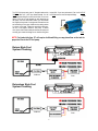
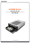
NOTE: Fuel tanks taller than 18” will require a bulkhead fitting or sump placed low on the tank for
proper fuel flow to the EFI fuel pump.
Return Style Fuel
System Plumbing
100 Micron
70160
Returnless Style Fuel
System Plumbing
100 Micron
70160
5
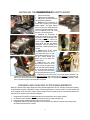
INSTALLING THE POWERJECTION III THROTTLE BODY
1. Disconnect the battery.
2. Remove fuel lines and linkage.
3. Left-Remove the carburetor following manufacturer's guidelines.
4. Right-Install the Powerjection III
throttle body insulating and mounting
gasket supplied. This gasket reduces
heat to the fuel in the throttle body and
features reinforcement bushings to prevent over-tightening which can cause
distortion of the mounting flange.
5. Left-Install the Powerjection III
throttle body assembly onto your manifold. Note: You may need longer carburetor studs: use #20151. Connect your
throttle linkage and the throttle return
spring. Mount with nuts and washers
and tighten. The ECU grounds in the
throttle body. A throttle return spring can
be used
6. Right-install the 3/8-NPT Coolant
Temperature Sensor into one of
the manifold water ports. You may
need a reducer bushing from 1/2‖ to
3/8‖ NPT. Connect harness from
throttle body to the coolant temperature sensor.
7. Right-Connect your power
brake booster vacuum line to the
3/8 inch vacuum port (yellow arrow)
on the rear base of the throttle body
or to a suitable intake manifold fitting. Connect all full time vacuum
lines like the transmission to this port.
8. Left-Ported Vacuum (white arrow) is for vacuum advance distributors. The
full time vacuum port (red arrow) is for the MAP sensor ONLY which is built into the ECU. DO NOT tee into this line. The
MAP line can be moved to the pressure side of the intake if used on a supercharged draw through application. Make
sure to use cable or zip ties to secure the MAP connections.
CRANKING AND CHARGING SYSTEM REQUIREMENTS
Modern EFI systems require tighter voltage control than carbureted applications The ECU, fuel pump and injector fuel delivery
are all affected by increases or decreases in voltage. Cranking voltage dropout is a common cause of a no-start condition with
an EFI equipped vehicle as the ECU needs a minimum voltage to function properly. Here are some electrical parameters to
verify before you complete your Powerjection III installation.
1.
2.
3.
4.
Voltage at the ECU and KEY wire during cranking must be greater than 9 volts for proper operation.
The alternator must be capable of supporting the extra load of the EFI system and fuel pump.
Operating (running) voltage should be at least 13.5 Volts at the ECU.
Voltage drops caused by corroded battery cables or poor connections can cause ECU drop out while cranking. Check
your battery cables and replace if suspect.
6
WIRING HARNESS INSTALLATION
Always use the same or larger gauge wire than the wire you
are splicing. Soldered connections are superior to butt splices
in most applications. Use heat shrink tubing when soldering.
Butt splicing while efficient can result in a poor connection
over time because of heat, oxidation and vibration.
NEVER twist wires together and tape them.
NEVER attach any EFI connection to the coil from Powerjection when using a capacitive discharge ignition amplifier or multi spark system. Doing so voids warranty and
will destroy the ECU!
RED (12V) 12 Volt fused wire goes directly to the
battery or to a battery disconnect switch.
Battery disconnects are acceptable if the
system is allowed to power down and
save data for 1 minute before disconnection from battery power.
YELLOW (KEY) ―Must be connected to the ignition
switch as a power source. The connection must
have power in the Crank position and On / Run
position. Verify that voltage does not drop below 9
volts at the connection when cranking the engine.
Do not use the choke wire or the (+) coil
(points type distributors) as this can be
variable, low voltage or may drop out.
BLACK (SP) TACH input. Connect to the (-) coil
wire in a standard distributor/coil application or the
TACH terminal of an HEI distributor.
If using a multi-spark or capacitive discharge ignition system or computer controlled distributor connect to the
Tach output of the ignition amplifier or distributor. DO NOT connect to the (-) coil terminal!
GREEN (CP) Spark Output — Connect to the Points Input of a multi-spark amplifier or capacitive discharge ignition system if using a fixed advance (locked out) 2-wire distributor ONLY. In all other applications this wire can be taped back into
the harness.
ORANGE (PUMP+) 12 Volts output to run the fuel pump. Connect to the positive side of the electric fuel pump
Can also be connected to the KEY input of the 70035 Fuel On Demand to power it up with the EFI system.
If using an existing fuel pump, connect to the previously installed power feed. The orange wire can also trigger a
relay to run the fuel pump if desired.
BROWN (E85) Ground if running 100% E85 mixture or apply 2.5 Volts if running 50% E85. Not used in most applications.
DISTRIBUTOR AND SPARK CONTROL SETUP
Set the Tach Input in the Dashboard Setup —> Main Setup to 2-Wire
Timing control requires a locked advance distributor—NO centrifugal
advance.
1. Check with your distributor manufacturer about locking out the advance mechanism and lock the advance system down.
Purchase a lockout mechanism for your distributor from
the manufacturer if necessary.
1. Install the distributor at 10 degrees before TDC mechanical advance
in all applications.
This is the reference advance (adjustable in Dashboard)
1. Do not use vacuum advance on your distributor if equipped!
2. Connect the 2-wire input of Powerjection (Violet/Purple) to the 2-wire magnetic pickup of the distributor.
3. Start the vehicle.
4. Verify your timing is 14 degrees total advance at idle at the crankshaft.
Note: All factory Powerjection calibrations come with 14 degrees advance at idle.
7
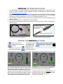
DASHBOARD SOFTWARE INSTALLATION
1.
2.
3.
4.
5.
The supplied software is compatible with Windows XP through Windows 7 operating systems. You will need a PC with a
CD drive to complete the installation. Software and updates are available for download from the Professional Products
forum: www.professional-products.com/forum
Insert the Dashboard CD into your CD or DVD drive. The Install Wizard will pop up and guide you through the installation
process. If the Wizard does not open, go to My Computer and double click the proper optical drive. The Install Wizard
should pop up to continue the install process. If not, click on ―P3 Fuel Injection Dashboard V3_0.exe‖
Once the software is installed into your laptop, you will need to physically connect your PC to the Powerjection III throttle
body ECU connector.
Ensure that connectors fully seat or communications will not be established.
Keep data cable away from spark plug wires, ignition amplifiers, and other noise sources to prevent communications issues from occuring.
Throttle body cable with
dust cap removed.
Replace dust cap when
not connected .
To laptop
Connection to PC
To Powerjection III
The two cables shown above will allow you to
connect your laptop to the Powerjection III.
Connect the other end of the cable assembly into
the single pin connector from the throttle body.
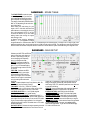
RUNNING THE DASHBOARD SOFTWARE
Click this icon to open the
Dashboard software and connect
to your ECU.
Click this icon to open the Log
Charter to view stored data logs.
The Dashboard software
will now search for your
ECU. Make sure the
ignition key is on. The
software will continuously search for the ECU.
Shown is the Main Dashboard when the ECU is disconnected
(left) and connected (right). All functions are available from the
Main Dashboard other than reviewing Data Logs. If you wish
to connect to your ECU when offline, click on the yellow CONNECT button. When connected the yellow square will change
to green. Once connected it will read the calibration from the
ECU and display current operating conditions of the engine.
The signal lights at the bottom indicate when individual functions are active (Green or Red) or inactive (Gray) .
To log data while driving, click on the DATALOG switch in the
lower right. It will then turn red while recording and white when
not recording. Files are saved to your laptop at:
C:\P3 EFI v3_0\EFI Log Files
8
IDLE ADJUSTMENT PROCEDURE
NOTE: Any mechanical adjustment to the throttle stop screws will require you to go to:
SETUP —> CALIBRATE TPS and click on CALIBRATE TPS MIN .
This procedure assumes the primary to secondary throttle link adjustment is
correct and that you have appropriate fueling established at idle. If not, close
both throttle blades completely. Adjust the primary to secondary throttle link
to remove all play between the primary and secondary shafts. Open the
secondary blade one turn and then the primary blade one turn from contact.
This will be your ―zero‖ adjustment.
Preparations:
1. Make sure the engine is at full operating temperature Make sure it's at thermostat temperature or slightly
higher.
2. Open Real Time ECU Data or IAC
3. Check that TPS is reading 1% or less
4. If TPS is higher than 1% then CALIBRATE TPS MIN
5. If the engine is idling significantly lower or higher than the
IDLE RPM TARGET, adjust the throttle blades with the
idle stop screws a minimum of 1/4 turn each, then CALIBRATE TPS MIN
6. When making throttle adjustments, adjust the front and
rear idle stop screws the same amount. If you move the
front 1/8 turn move the rear 1/8 turn. This is required for
proper mixture distribution and best idle quality.
Automatic transmissions:
1. Set your desired IN-GEAR idle RPM with the IDLE RPM
TARGET vs. Coolant Temp F table under EDIT —> IAC
2. Set your PARK/NEUTRAL RPM approximately 100-150
RPM higher than the IN-GEAR settings with the mechanical throttle stops. This will vary with the camshaft and
torque converter characteristics.
3. IN-GEAR IAC counts at full operating temperature should
be less than 40 ideally but may be more depending on
the torque converter stall speed and camshaft choice.
4. CALIBRATE TPS MIN
Manual transmissions:
1. Set your desired idle RPM with the IDLE RPM TARGET
vs. Coolant Temp F table under EDIT —> IAC
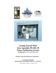
2. Adjust the Idle Stop Screws so that you have between 4
If you get lost, close both the front and rear blades fully and
and 12 IAC POS counts while viewing the REAL TIME
then open the rear and front screw one full turn. Then CaliECU DATA or IAC. See image below as a guide.
brate TPS Min.
3. CALIBRATE TPS MIN
Above: IAC is reading in the proper range of 4-15 counts for a Manual transmission and TPS is reading 1% or less at idle
9
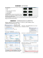
DASHBOARD - MENU FUNCTIONS
Open calibration from file - Loads a calibration to the ECU from your laptop.
Note: You must KEY OFF until the ECU disconnects from the Dashboard
software before re-starting the engine after loading a new calibration.
Save calibration to file - Saves your currently loaded calibration to your laptop. Note: May not be the stored calibration in your ECU.
Read calibration data from ECU - Reads the current running calibration into
laptop memory. Does not save the data to your laptop.
This is the installation directory for Powerjection Calibrations on your laptop:
C:\P3 EFI v3_0\EFI Calibration Files
These are the main adjustment tables and that you will use to properly calibrate the ECU to your specific engine.
Fuel Table - Represents the base map fueling in pulse width.
Target Air/Fuel - Air Fuel ratio the ECU is attempting to achieve.
Learn Fuel - Adjustments the ECU has made to fueling from the base table.
Learn Cell Protect - Enables or disables ECU learning cells.
Accel/Decel - ―Pump Shot‖ functions and fuel cut off.
Crank/Cold Engine - Starting parameters and cold operation adjustments.
IAC - Idle Speed and Idle Air Control functions.
Spark Table - Commanded spark timing table.
Main Setup - RPM, MAP and/or TPS range setup, Learn and Closed Loop
Enable, Tach Input, Cylinder Selection, Idle cell, Fuel Mode, Fuel Blend, TPS
Mode or MAP Mode, Boost setup.
Fuel Wizard - Base fuel map setup via cam & intake manager, Max Torque,
Injectors, Injector flow rate, Boost, Torque Sliders vs. RPM.
Spark - Spark system parameters, RPM and MAP and/or TPS range setup.
Rev Limiter, Pickup Input Delay, MAP or TPS mode switch
Calibrate TPS - Calibrate the minimum & maximum TPS position
Real-Time ECU Data - View Live Data from the ECU and
covers all parameters that can be logged by the data logger.
Histogram - Graphic representation of specific live data.
Also creates bookmark events in data logs for easier review.
About - Lists Dashboard Version, Firmware Version and the COM
port used by your laptop.
Disable Auto Connect - Turns off the Auto Connect function if working off line or if you do not want Dashboard to search for your ECU.
This function disables (no check mark) after Dashboard 3.0 is closed
and goes back to searching for the ECU the next time it is opened.
10
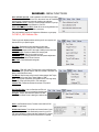
DASHBOARD - EDIT MENU
Learn Fuel shows what the ECU is adding or
subtracting from the Fuel Wizard or Fuel Table
to keep the AFR on Target. The ECU has a limit
of +/- 25% from the base calculations. There’s
no ―right‖ value for Learn Fuel only that the system is adjusting properly. If you are seeing learn
values of -25% or +25% in many places you will
need to make adjustments to the Fuel Wizard (in
automatic mode) or the Fuel Table (in manual
mode), to bring the fueling in line. Note: If you
change the Fuel Wizard substantially and do not
clear the Learn Fuel table the ECU will use the
stored Learn Fuel values to make additional
corrections. It is advisable to clear the Learn
Fuel when making significant changes to the
Fuel Wizard or Fuel Table.
Target Air/Fuel sets the AFR that the ECU is
attempting to achieve vs. RPM and either TPS
or MAP (see Main Setup). The base calibration
should be very close for most naturally aspirated
engines.
For normal gasoline motors 14.7 AFR is considered stoichiometric. For 10% Ethanol Blends it is
14.4 AFR. Wide Open Throttle AFR for naturally
aspirated engines should be in the 12.4-13.1
AFR range. Boosted engines will be richer than
12.0 generally.
To richen a cell decrease the value, to lean out
a cell increase the value. Wide open throttle is to
the right of the table and high vacuum is on the
left side.
It is not recommended to set AFR leaner than
15.0 at cruise or at higher manifold pressures (68+ kPa) as engine damage could occur. However the Idle cell can be leaner
with very large camshafts to promote a better idle quality.
Fuel Table - Shows you the cell you are operating in along with AFR, Target AFR, and final Injector Pulse Width. In Automatic
Mode this table represents the underlying fuel calculations from the Fuel Wizard and is not adjustable.
In Manual Tuning mode the adjustment buttons (+ - x / ) are available to
change the fueling per RPM and either MAP or TPS depending on the
selected mode in Main Setup. To
change a cell or range of cells, Click
and Drag around the cells, use the
math functions to modify the cells and
click SEND. The changes are output
to the ECU once SEND is clicked.
Used in conjunction with the Learn
Fuel table you can dial in your Fuel
Table to optimize the calibration for
almost any engine.
11
DASHBOARD - LEARN CELL PROTECT
Learn Cell Protect enables or disables
Adaptive Learning in individual cells. A one
(1) means that Learn Fuel is enabled in that
cell and a zero (0) disables Learn Fuel for
that cell.
You may wish to disable Learn Fuel in individual cells to keep the learned values from
changing. For example, you have the fueling dialed in at steady state but when you
transition, the engine goes momentarily
rich. You don’t want the ADL changing
things so you set that cell to zero to protect
it. This is also useful for Nitrous applications
where you do not want the Learn Fuel to
adjust the AFR when nitrous is enabled.
Note that Closed Loop adjustments will
continue even with cells disabled.
DASHBOARD - ACCEL/DECEL FUELING
Accel Settings control the transitional fueling of the engine. In carburetor terms this is
called Pump Shot. The Decel function reduces or removes fuel during a deceleration event to conserve fuel. To calibrate
Pump Shot you must have the Learn Fuel
optimized in steady state conditions. To
optimize the Pump Shot you will need to be
logging data and observe controlled throttle
transitions to determine the need of more
or less Pump Shot fueling. See tuning suggestions for more details.
AE PW (uS) - determines how much additional fuel is injected per injector cycle during a transition vs. differential TPS (change
in TPS% every 15 mSec). A rapid throttle
change will use values further down the
table than a slow throttle change. For example: you are idling and go to WOT immediately. The ECU will use the value at
100 TPS. However if you are cruising at 20% TPS and you
move the throttle to 36% TPS in that 15 mSec window, the
ECU will use the value at 16 TPS.
DURATION (mS) - Determines how long the AE PW is held
on after the first injection pulse vs. differential TPS like AE
PW. This will affect the overall amount of fuel that is injected
during a throttle transition. Larger values will keep the Pump
Shot in longer and shorter values will reduce the pump shot.
DECEL - Applies a fixed pulse width - PULSE WIDTH - when
IF RPM IS GREATER THAN is above the set point and AND
TPS IS LESS THAN is less than the set point. The pulse width
can be set to zero (no fuel in decel) or to a set pulse width.
Having a minimum pulse width can reduce exhaust rumble or
backfire as the engine transitions to decel mode.
12
DASHBOARD - CRANK / COLD ENGINE SETTINGS
The Crank / Cold Engine settings alter fuel calculations dependent on coolant temperature.
Additional fuel is required on a cold engine because fuel evaporation does not begin until about
120 F and rates are much lower at cold temperatures. The engine may need to as little as 15%
fuel added or more than 45% added than a warm
engine. Even with EFI injectors superior spray
pattern, the fuel requires additional heat and
mass to produce adequate running conditions.
CRANKING - Fuel amount that is injected when
the RPM is between 35 RPM and 400 RPM. All
four injectors operate at once in cranking mode.
If your engine fails to go above 400 RPM during
cranking, you may need to alter the pulse width.
PUMP PRIME - Time that the fuel pump runs before shutting
down if no tach pulses are received. Note: It is advisable to
start the engine while the fuel pump is running. This can be
adjusted between 1 and 60 seconds of run time.
FUEL PRIME DURING CRANKING / FUEL PRIME BEFORE
CRANKING - Determines when the fuel prime shot is injected
into the engine. Only select one option. Fuel Prime Before
Cranking will put the prime shot in 1 second after Key-On. This
is helpful to diagnose that the ECU is operating correctly as no
prime shot may indicate power loss or other wiring issues with
the ECU. Fuel Prime During Cranking will apply the prime shot
when the cranking RPM goes above 35 RPM.
FUEL INJECTOR PRIME (mSec) - Fuel prime shot during or
before cranking vs. coolant temperature. Increase or decrease
this to alter priming if your engine fails to leave cranking mode
(400 RPM). The prime shot pulses all four injectors for the
time period indicated.
AFTER START DECAY FUEL - This is the ―Choke‖ fueling
function. After Start adds additional fuel to the C-TEMP ENRICHMENT adder to help promote combustion when the engine is cold. Additional percent may be required for some engines. This fuel is decayed over the DECAY TIME period.
C-TEMP ENRICHMENT– Adds additional fuel for cold starting.
This is a percentage adder to the base table calculated from
the Fuel Wizard and Learn Fuel values.
DASHBOARD - IAC CONTROL
IAC CONTROL - Controls airflow going around the throttle
plates through the IAC orifice to keep the idle RPM on target.
It will also add additional airflow when off idle and decay it out
when returning to idle allow a soft idle return and control idle
speed during transitions off and to idle.
IDLE RPM TARGET - Target Idle Speed for the engine to idle
at vs. Coolant temperature. Set this table to the desired idle
speed with a manual transmission or the in-gear idle speed
with an automatic transmission.
With an automatic, park/neutral idle speed should be set with
the mechanical linkage approximately 100-150 RPM higher
than the in-gear setting at normal water temperature.
IAC CRANKING POSITION - This is the opening set point
position for the IAC in steps. Steps are from 0 to 190 where 0
= minimum airflow (IAC hole closed off).
IAC HOLD TIME - Time that the IAC is held open just after
startup. Adjustable for different temperature ranges.
DECAY STEPS FROM IAC HOLD - How fast, in steps, that
the IAC goes to Idle RPM following to keep the RPM steady.
IAC SPEED - Rate at which the IAC will chase the RPM error
from the set point. If this is set too fast the IAC will ―chase‖
itself and if it is set too slow the IAC won’t react quickly. On big
overlap camshafts a slower IAC can be beneficial.
IDLE FOLLOWER - Maximum RPM and TPS to enable the
ECU to control idle speed.
THROTTLE FOLLOWER - Adds OPEN IAC STEPS to the
current IAC position when TPS is above the AND TPS LESS
THAN set point and less than IAC POSITION set point. This
allows a soft and controlled return to idle.
13
DASHBOARD - SPARK TABLE
The SPARK TABLE controls the spark
advance of your engine if you have a 2wire locked advance distributor and an
ignition amplifier or multi-spark system.
The table is referenced by RPM and either
MAP or TPS depending on the mode chosen in Main Setup.
When setting the initial timing for your
engine, refer to this table and match the
spark advance on the table with what you
see at the crankshaft. NOTE: Do not put
too much idle advance or you can create
stalling issues when revving the engine
and returning to idle.
In Manual Tuning mode the adjustment
buttons (+ - x / ) are available to change
the spark advance vs. RPM and either MAP or TPS depending on the selected mode. To change a cell or range of cells, Click
and Drag around the cells, use the math functions to modify the cells and click SEND. The changes are output to the ECU once
SEND is clicked. Be cautious with spark advance as there is no knock detection system. Minimum timing is 10 degrees BTDC.
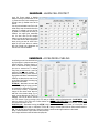
DASHBOARD - MAIN SETUP
Calibrate your MAP/TPS and RPM so
that you have larger cells where you
do most of your driving so that you
are not changing cells frequently
when in a steady state mode.
MAP/TPS - Calibrates the MAP or
TPS range breakpoints for your engine. For a 10 PSI boosted application the MAP range would be 20 kPa
to 170 kPa.
FUEL RPM - Calibrates the RPM
range breakpoints for your engine.
Set the maximum RPM at the rev
limit for your engine. 400 is the fixed
minimum as the engine is considered
to be in cranking fuel mode below
400 RPM.
LEARN - Enables Adaptive Learn Fuel (Red=On) C/L - Enables Closed Loop fuel control (Red=On)
TACH INPUT - Use Coil (-) TACH OUT (default).
For distributors with a 2-wire reluctor output use the 2-Wire
setting which allows spark control only in this mode.
CYLINDER SELECTION - 4, 6, or 8 cylinder engines
(8=default). Rotaries use the 4 cylinder setting.
MAP/RPM OR TPS/RPM MODE - Speed density (MAP <—
most common) or Alpha-N (TPS<—special cases) selection. If
your engine has very low vacuum you can use the TPS mode
to give you more stable engine operation. You will need to
calibrate the Boost kPa and % Fuel adder when in TPS mode
boosted applications.
IDLE CELL SETUP - Declares the engine operating in the Idle
Fueling Cell. Can be disabled with the check box so there is
no idle cell. It is advisable to enable the Idle Cell function to
keep give the engine a stable idle zone separate from the
main fueling. RPM, TPS, and MAP parameters must all be met
to enter idle cell fueling.
FIXED PW - Keeps the idle pulse width consistent independent of manifold pressure or RPM when in the Idle Cell.
IF RPM LESS THEN - MAX RPM for Idle Cell Enable
AND TPS IS LESS THAN - MAX TPS for Idle Cell Enable
AND MAP IS LESS THAN - MAX MAP for Idle Cell Enable
FUEL MODE - Automatic —Fuel Wizard generated fueling.
Manual - allows you to fine tune the fuel table to your engine.
FUEL BLEND OFFSET - Works with the Brown wire grounded
to enable additional fuel (in percent) to be added globally.
Used for E85 applications. To get the 50% E85 Blend apply
2.5 Volts to the Brown wire.
14
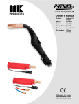
DASHBOARD - FUEL WIZARD
Use the Fuel Wizard to set up a base table for
either Automatic tuning mode or Manual Tuning
mode of the fuel table. The wizard shapes the
torque (fuel) curve of your engine based on your
inputs. Torque raises and lowers the overall fueling
where Manifold and Cam shape the curve.
Warning: If you press CALCULATE after altering
your Manual Fuel Table it will be reset to the configuration in the fuel wizard and sent to the ECU.
DO NOT press CALCULATE if you have a customized Manual tune!
CALCULATE - Recalculates the entire fuel table
and sends it to the ECU after changes are made to
the Manifold and Cam selectors.
TORQUE - Max torque at the wheels that the engine will produce in foot lbs. To estimate rear
wheel torque subtract approximately 60-100 ft/lbs
from an engine dyno torque specification.
# OF INJ - Number of fuel injectors installed (4 for
Powerjection 3)
BOOST - Maximum Amount of Boost (PSI). Zero for naturally
aspirated or nitrous motors.
INJ FLOW RATE - Flow rate of the injectors in lbs/hr at the
operating pressure (45 PSI). 62 is default.
MANIFOLD TYPE - Alters the torque curve based on manifold
design. A stock manifold will move the torque down low and a
single plane intake will move the torque curve to high RPMs.
CAM TYPE - A stock cam will require more fuel (torque) at the
lower RPMs and much less at top RPM. A high duration/high
overlap cam will require less fuel at the low RPMs and much
more at the mid range and top RPMs.
SLIDER UPDATE LOCKED/UNLOCKED - Unlock (toggle up)
if you are using the Manifold & Cam selections to create the
base fuel calibration.
SLIDER UPDATE UNLOCKED -Lock the green slider bars
(toggle down) so that when you press ―CALCULATE‖ your
customized slider selections will not be altered.
TQ SLIDERS (Green bars) - Sets the percentage of maximum
torque for your engine combination at individual RPM steps.
Input your complete torque curve for your engine by calculating the percent of maximum torque for each RPM step.
DASHBOARD - CALIBRATE TPS
You must calibrate the throttle position sensor any
time you make a mechanical adjustment to the throttle blade position or if you replace the TPS sensor.
Begin with a closed throttle and click Calibrate TPS
Min. Now hold the throttle wide open and click Calibrate TPS Max. Your TPS is now calibrated.
This error will occur if you attempt to Calibrate TPS Max
TPS percentage can be viewed by clicking View —>
before Calibrate TPS Min.
Real Time ECU Data or EDIT —> IAC
If your TPS reads 100% when the throttle is closed,
you must calibrate it or the engine will not start be- Note: You may Calibrate TPS
cause it will enter Clear Flood (flooded engine) Min with the engine running or
mode.
not running.
When you press Calibrate TPS Min or Max the bar DO NOT Calibrate TPS Max
turns green while clicking and returns to gray after- with the engine running.
wards. The calibration is complete when you see the
bar turn green while clicking it.
15
DASHBOARD - SPARK SETUP
NOTE: Spark parameters are only applicable
when using a 2-Wire Distributor and it is
selected in MAIN SETUP
Calibrate your MAP/TPS and RPM so that you
have larger cells where you do most of your
driving so that you are not changing cells frequently when in a steady state mode.
MAP/TPS - Calibrates the MAP or TPS range
breakpoints for your engine. For a 10 PSI
boosted application the MAP range would be
20 kPa to 170 kPa.
SPARK RPM - Calibrates the minimum (Fixed
at 400) and maximum RPM range breakpoints
for your engine. Set the maximum RPM at the rev limit for your
engine.
PICKUP INPUT DELAY - Calibrates the offset time for your
reluctor input at high RPM. Increase/decrease if you have a
timing discrepancy between calculated advance (in the Spark
Table) and actual advance at the crankshaft.
REV LIMIT - RPM that the rev limiter should take action
NUMBER OF MISSED SPARKS - How many spark events
are missed per number of VR inputs (Reluctor Inputs) Raising
this value will cause a harsher rev limit.
NUMBER OF MISSED VR INPUTS - How many reluctor inputs are used to produce a proper rev control. The base settings are for a V8 engine and generally do not need to be
changed. Higher Missed VR Inputs make a softer the rev limit.
Numbers should always be odd (5,7,9,11,13...).
DASHBOARD - REAL TIME ECU DATA
This screen allows you to see
all parameters the ECU logs.:
RPM
MAP / Vacuum
Water Temperature
ECU Temperature
Coolant Enrichment
Learn Fuel Percentage
Closed Loop Percentage
Cell (1-50 Corresponds to
RPM/MAP Cells)
Air Fuel Ratio
Targeted Air Fuel Ratio
Battery Voltage
IAC Target
IAC Position
Targeted Idle Speed
Battery Compensation
Total Run Time
Throttle Position Percentage
Maximum Allowed Injector Pulse Width
Base Pulse Width (Manual Mode ONLY)
Injector Pulse Width
Injector Duty Cycle Percentage
Injection Mode (Manual, Automatic,
Cranking, Decel)
Tach Input (Coil or Reluctor)
Spark Advance in Degrees
Initial Offset (for locked out distributor
with phased cap)
IAC Status Lights:
Close Position—Closing IAC during shutdown
Crank Position—Open IAC to Crank
Position
After Start Hold—Timed IAC hold
RPM Follower—Controlling Idle RPM
Temp Based Mode—Used in Step-based
Mode
Stall Saver—Stall saver active in Step
Based Mode
Manual Mod—Enabled
16
Other Items—Enabled is Green
Key—Key switch is on
Fuel Pump Relay—Enabled
Tach Pickup—Receiving tach input
02 Sensor—In Ready condition
Closed Loop—Enabled
Learn Fuel—Enabled
After Start Fuel—Enabled
Cranking—In Cranking Mode
Gasoline—Fuel is gasoline
50% E85—Fuel is Mixed E85
100% E85—Fuel is 100% E85
DASHBOARD - HISTOGRAM
This feature allows you to see what is occurring in real time along
with peak values for:
RPM
TPS
MAP / Vacuum or Boost (selectable)
Injector Pulse Width
A / F (Air Fuel Ratio)
Battery Voltage
Under the MAP screen is a choice of "NA" and "BOOST." Click the
appropriate one for your application. It changes the scale for load
on the left side of the MAP screen. Clicking ―Reset All‖ will reset the
peak values that have been recorded.
If you are data logging, you can click ―Bookmark‖ to mark a specific location you saw while observing the histogram for ease in
finding this event while reviewing the data log
DASHBOARD - LOADING/SAVING A CALIBRATION
All base calibration files are located in: “C:\P3 EFI V3_0\EFI Calibration Files”
Calibration file extensions end in “.P3C”
Click on File —> Open
Click on File —> Save calibration to file to save your modicalibration from file to
load a new file to your ECU. fied calibration to a new file.
Click ―OK‖
Click Computer —>{Hard drive}(C:) and double-click (C:)
Click Computer —>{Hard drive}(C:) and double-click (C:)
Double Click on P3 EFI v3_0 —> EFI Calibration Files and
select ―300TQ_Base.P3C‖ for the base calibration. Press OK
Double Click on P3 EFI v3_0 —> EFI Calibration Files and
name the file. Click Save when done.
Turn the ignition KEY OFF. Allow the ECU to disconnect from
the Dashboard software before re-starting the engine after
loading a new calibration to allow the ECU to save the data.
17
CALIBRATION FOR STARTUP
1.
2.
3.
4.
5.
6.
7.
Turn the Key on and connect to the ECU with a laptop.
The fuel pump will come on for 15-20 seconds and shut
off. This is a safety feature of the Powerjection system. In
case the vehicle is in an accident where the engine shuts
off the fuel pump will also shut off.
You should see and / or hear the ―Priming Shot‖ of fuel
when the key is turned on. This shows the ECU is functioning properly, and that battery and key power exist in
the ―Run‖ or ―On‖ position.
Make sure fuel pressure is at 45 PSI while the pump is
running. If you have a Fuel On Demand returnless system the pressure may vary somewhat with the engine off:
this is normal. You can type ―TOOL” on your keyboard to
use the fuel pump relay controls to enable the relay and
set your fuel pressure.
Calibrate your TPS Minimum & Maximum
Verify the RPM range of your engine in Main Setup. The
base calibration range is 400 - 5500 RPM
Check that you have a reasonable torque setting in the
Fuel Wizard for your engine. Verify your Manifold & Cam
choice.
8.
9.
10.
11.
12.
13.
14.
Save a copy of your modified calibration using File ->
Save Calibration to File
Key Off for a minute to allow the ECU to save data.
Start the engine.
Observe the Air Fuel Ratio - Cold engines (below 70 F)
need to be in the mid to high 12 AFR range for proper
starting and running for the first 30 seconds. Warmer
engines may have AFR’s in the mid 13’s to low 14’s.
After coolant temperature exceeds 70F Closed Loop will
enable and the ECU will begin to control the fueling of the
engine.
Allow the engine to warm to 145 F where Learn Fuel is
enabled, view the Learn Fuel Table to see if you need to
add or subtract fuel. If your Idle Cell is reading +25 or –25
you need to add fuel (+25) or subtract fuel (-25) This can
be achieved by changing the torque +/-25 or by altering
the cam or intake choice.
Once the engine is at full operating temperature you can
proceed to idle speed adjustments.
ADJUSTING THE FUEL WIZARD
To properly calibrate your Powerjection system you need
some information about your engine. If you are missing information you can calibrate around the missing information although the calibration procedure may take longer.
1. Engine torque—either wheel
torque or engine torque
2. Camshaft duration to determine engine operating range
3. Intake manifold type
Start and run the engine with the Learn Fuel table open. Note
the values in the Learn Fuel Table. Note: Any time you
change the cam, intake, or torque values the ECU will still
retain the Learn Fuel values. Either edit the Learn Fuel values In this example, the cam and intake choice should be made
directly or click Clear LF to clear all of the learned values.
less aggressive to add low RPM fuel and less high RPM fuel.
In this example, the cam and intake choice should be made In this example, the engine simply needs more fuel across the
more aggressive to remove low RPM fuel.
board. Increase the Torque (10-25 ft/lbs) then click on the
Calculate button in the Fuel Wizard.
18
ADJUSTING THE FUEL WIZARD SLIDERS
The fuel sliders in the Fuel Wizard allow you to move the fuel
curve for your exact engine combination. The UP / DN buttons
alters fuel 1% at a time at individual RPM breakpoints. If you
are observing your Learn Fuel values per row you can customize the fuel sliders to minimize the Learn Fuel excursions from
the zero point. To see the Learn Fuel adapt at idle, alter the
fuel sliders in the idle range and wait for the Learn Fuel to
move. Once Learn Fuel moves towards zero you are done continuously adjusts for atmospheric conditions and engine
with that range. Evaluate each RPM range to optimize fueling. variations. Evaluate individual RPM rows in the Learn Fuel
Note that the Learn Fuel will not be zero across the board as it Table for best fueling for that range.
SPARK SETUP
If you are running a locked advance 2-wire distributor and an
ignition amplifier you can take advantage of the spark control
parameters of the Powerjection III EFI system.
The Spark system can be run in Speed Density (MAP) mode
or Alpha-N (TPS) mode. Alpha-N adjustments are TPS and
RPM based where Speed Density is MAP and RPM based.
The initial (static) advance should be 10 degrees with base
calibrations. You should see 14 degrees advance at the crankshaft. Synchronize the distributor to 14 degrees if you see
higher or lower timing. Minimum spark advance is 10 degrees.
An average motor will need between 10-20 degrees of timing
at idle and 25-40 degrees of timing at wide open throttle depending on the combination of parts. High vacuum conditions
lower your cylinder
pressure and allow
more advance. Our
base calibration has
32 degrees at wide
open throttle. The
total range of adjustment is 30
crankshaft degrees. All of our calibrations have 14 degrees of
timing at idle so that you can synchronize the EFI commanded
spark with spark advance at the crankshaft easily. The initial
offset can be adjusted in advanced tuning which is described
on our forum. (See Page1 for link)
IGNITION PICKUP INPUT DELAY
Since there are a variety of ignition reluctor types available we
have an Ignition Pickup Input delay. The programmed value of
450 is suitable for most types. The adjustment procedure is to
synchronize your timing at idle by adjusting the distributor to
14 degrees at idle and then checking your advance at higher
RPM to make sure the commanded spark advance is equal to
the actual spark advance. For example, you have 32 degrees
of timing commanded but you are seeing 28 degrees at 3500
RPM (no load). You need to increase the Pickup Input Delay.
Conversely, if you have 32 degrees commanded, and you are
seeing 36 degrees at 3500 RPM then you need to decrease
the Pickup Input Delay.
You can also type ―TOOL‖ on the
keyboard to open the ECU Control/Test function and set a fixed advance by clicking the
Fixed Timing and putting in a timing value. The ECU will then
output the Fixed Timing value and you can time your engine
ECU CONTROL/TEST MENU
The ECU Control/Test menu can be accessed by typing ―TOOL‖ on
your keyboard. This menu allows you to control some functions of
the ECU manually.
The Fuel Pump relay can be enabled and disabled. Useful for diagnosing startup Air Fuel ratios and setting fuel pressure regulators.
The IAC can be stepped open or closed one step at a time.
You can control your injector pulse width (BE CAUTIOUS!) and
your Ignition timing (BE CAUTIOUS!) by placing values in the boxes
and clicking the appropriate button. The system can reverted back
to ECU control by clicking Normal Mode for the specific functions.
19
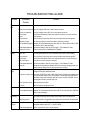
TROUBLESHOOTING GUIDE
Issue
Possible
Cause
Engine won’t Battery fuse blown
start
Action
Check fuse on main harness. Replace with same size fuse if blown.
Battery wire not hooked up Check for voltage to RED wire in main harness connector
Key wire not hooked up Check for voltage to yellow KEY wire in main harness connector
No tach signal
Verify RPM on Dashboard. Check black coil/tach connection or 2-wire connection.
No fuel
Fill up gas tank.
No fuel pressure
Prime fuel pump. Check pump wire connections. Adjust fuel pressure regulator.
Low battery voltage
Use Data Log software to check for at least 9 volts during cranking
TPS not adjusted properly Calibrate TPS in Dashboard software. Must read 1% or less at idle. See REAL TIME
ECU DATA or IAC to view percentage.
Throttle blade adjustment
Cranking PW too low
Engine starts No power during cranking
but dies
to KEY wire
Open throttle blades to allow air into the engine.—Then Calibrate TPS Min
Increase cranking PW in CRANKING/COLD ENGINE
Check for voltage to the key wire (yellow) while cranking—Take a Datalog of the engine starting and determine if ―KEY‖ parameter drops to ZERO while cranking
No fuel pressure
No tach signal
Loss of tach signal
Throttle blade adjustment
Corrupt file
Prime fuel pump. Check pump wire connections. Adjust fuel pressure regulator.
Verify RPM on Dashboard. Check black coil/tach connection or 2-wire connection.
Check wire for a loose or broken connection.
Open throttle blades to allow air into the engine.—Then Calibrate TPS Min
Reload last known good base calibration file. Check cranking/ charging system with
datalog software Battery must be above 9 volts during cranking.
EMS is still learning
Let the system learn. Run engine at low RPMs and steady loads first and work up to
the higher RPM ranges and steady loads
Engine runs
rough
Torque set too high or low Check your LEARN FUEL table or AFR. If Idle Learn Cell reads a large negative number, lower the Max Torque in the FUEL WIZARD. If the idle cell in the LEARN FUEL
table reads a large positive number, raise the Torque in the FUEL WIZARD. Zero to
slightly negative is best in the Idle Learn Cell.
High Idle
Low or high fuel pressure Adjust fuel pressure to 45psi.
Out of fuel
Make sure there is enough gas in tank.
Throttle blade adjustment Close throttle blades to allow less air into the engine.—Then Calibrate TPS Min
TPS not adjusted properly Calibrate TPS in Dashboard software. Must read 1% at closed. See REAL TIME ECU
DATA to view percentage.
Hesitation on Throttle blades not set 1 to After desired throttle blade adjustment is reached use the adjustable progressive linkacceleration 1
age to make the primary and secondary throttle blades open at the same time.
Losing fuel pressure
Engine stalls Decel RPM set to low
on Decel
Check fuel system for clogged filters, pinched fuel lines, and leaks in the fuel system.
Raise the RPM under DECEL in ACCEL/DECEL table. This can be found in the
Dashboard software under EDIT —> ACCEL/DECEL .
Throttle blade adjustment Refer to instructions on how to set idle properly.
20