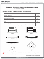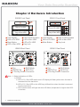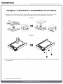
1
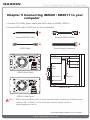
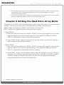
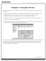
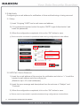
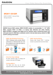
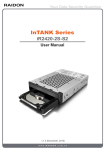
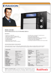
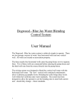
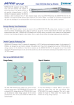
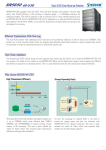
InTANK Series
iR2620-2S-S2 / SR2611-2S-S2R
User Manual
iR2620-2S-S2
SR2611-2S-S2R
v.2.2 (Jun, 2011)
Index
Chapter 1 Check Package Contents and Accessories.....................................3
Chapter 2 Hardware Introduction..................................................................... 4
Chapter 3 Precaution before Usage.................................................................5
Chapter 4 Hardware Installation Procedure.....................................................6
Chapter 5 Connecting iR2620 / SR2611 to your computer..............................7
Chapter 6 Setting the Hard Drive Array Mode..................................................8
Chapter 7 Computer Set Up.............................................................................9
Chapter 8 Hard Disk status on LCD screen..................................................... 10
Chapter 9 Data Rebuilding Operation.............................................................. 11
Chapter 10 GUI Monitoring Software & FW Updating........................................ 12
Appendix : Trouble Shooting / Q&A..................................................................... 16
Chapter 1 Check Package Contents and
Accessories
iR2620 / SR2611 system includes the following:
Item
Quantity
iR2620 / SR2611
1/1
Internal RS232 Cable
1
External RS232 Cable
1
SATA Cable
1
CD
1
Accessory bag
1
iR2620 : includes 6 of screws for device, 6 of screws for HDD tray, and 2 of keys for key lock
SR2611 : includes 8 of screws and, 2 of keys for key lock
iR2620
SR2611
Internal RS232 Cable
External RS232 Cable
SATA Cable
Accessory bag
CD
Note : Please check above parts are included prior to installation. The accessory bag contains
screws and a plastic key.
Check Package Contents and Accessories 3
Chapter 2 Hardware Introduction
iR2620 Front Panel
2
1
SR2611 Front Panel
3
4
5
Tray of Pri HDD
Tray of Sec HDD
1
3
5
7
LCD Display
LED of Pri HDD
Mute Button
LED of Sec HDD
2
4
6
8
2
1
8
6
Tray of Pri HDD
7
Tray of Sec HDD
LED of Failure Alarm
LED of Sec HDD
LED of Pri HDD
Key Lock
1
3
5
LCD Display
LED of Pri HDD
Mute Button
iR2620 Real Panel
2
4
6
5
3
4
6
LED of Failure Alarm
LED of Sec HDD
Key Lock
SR2611 Real Panel
3
1
3
2
1
4
4
5
1
3
5
2 RAID Mode
Fan
RS232 Port 4 SATA Port
4 Pin Big Power Connector
2
5
1
3
5
2 RAID Mode
Fan
RS232 Port 4 SATA Port
4 Pin Big Power Connector
Note : 1. Status Indications of LEDs:
1) iR2620:
A. LED of Pri / Sec HDD which near LCD display will flash yellow when the data is
accessed from the hard drive.
B. LED of Pri / Sec HDD on the HDD tray will flash blue when the data is accessed
from the hard drive.
C. LED of failure alarm will light red when HD failed, temperature is higher than 60ºC
or fan fails.
4 Hardware Introduction
2) SR2611:
A. LED of Pri / Sec HDD will flash yellow when the data is accessed from the hard
drive.
B. LED of failure alarm will light red when HD failed, temperature is higher than 60ºC
or fan fails.
2. Mute Button : Press to turn on mute function, to shut off the buzzer alarm, just press the
bottom again.
Chapter 3 Precaution before Usage
1. Hardware Requirement
1) Computers or servers with SATA I& SATA II
2) Hard drive with SATA I& SATA II
2. Notices
1) iR2620 / SR2611’s brilliant design allows the user to simultaneously utilize two hard
drives manu factured by different companies. However, if the user expects better
efficiency, we strongly recommend the users to use hard drives manufactured by
the same manufacturer.
2) The iR2620 / SR2611 had undergone strict hard drive compatibility test. The result
shows that it is compatible with most hard drives on the market such as
Western Digital, Seagate, Fujitsu, Hitachi, and etc. However, due to the new types
of hard drives appearing on the market, if your hard drive is not compatible with the
system, please contact us through the following email:[email protected]
and we will reply as soon as possible.
3) The iR2620 / SR2611 is equipped with a ball bearing cooling fan that will provide
effective cooling for the 7200 & 10000 rpm hard drive. We highly recommend using
computer chassis with effective cooling design to avoid disk array crashing due to
ineffective cooling.
4) iR2620 / SR2611 supports RAID 0 & RAID 1.
Precaution before Usage 5
Chapter 4 Hardware Installation Procedure
1. Install your hard disks into the removable trays and secure them with the screws from
accessory kit. This will protect your hard disk from any unnecessary movement.
iR2620
SR2611
2. Once the hard disks have been installed, insert the removable trays into device and close
the handles.
6 Hardware Installation Procedure
Chapter 5 Connecting iR2620 / SR2611 to your
computer
1. Connect DC12V&5V power cables and SATA cables to iR2620 / SR2611.
2. Connect SATA cable to SATA port on the motherboard.
2
1
Internal RS232 Cable
External RS232 Cable
4
3
SATA Cable
Power Supply Connector
Power Supply
1
4
iR2620 / SR2611
3
COM 1
4
COM 2
iR2620 Real Panel
3
2
Motherboard
SATA Ports
1
1
3
Internal Case
4
SR2611 Real Panel
Note : 1. RS232 Port and RS232 Cable: Provides hardware status monitoring to industrial control
system or IPC via RS232. If more information required, please contact at
[email protected]
Connecting iR2620 / SR2611 to your computer 7
2. We do not recommend users to disassemble the device without proper instructions and
authorization. The manufacture warranty will not cover the damages caused by
unauthorized disassembling.
3. To prevent the device from malfunction, please make sure the device is connected with a
direct and dedicated power connection of a stable power input.
Chapter 6 Setting the Hard Drive Array Mode
Please select the RAID mode with the jumper located at the back panel. The original default
is RAID 1, still there are three pins at the back panel for RAID mode selection:
RAID 0 mode by setting the jumper on the bottom of the two pins.
RAID 1 mode by setting the jumper on the top of the two pins.
1. RAID 0 Mode
1). Place two new hard drives into iR2620 / SR2611 and strongly suggest you to use two
identical hard drives to get the equal capacity. If the capacity is different, iR2620 /
SR2611 is downward to the small hard drive capacity.
2). Under RAID 0 mode, capacity is add up to a one big volume, also with the feature of
faster read/write performance efficient.
2. RAID 1 Mode
1). Place two new hard drives into iR2620 / SR2611 and strongly suggest you to use two
identical hard drives to get the equal capacity. If the capacity is different, iR2620 /
SR2611 is downward to the small hard drive capacity.
2). Under RAID 1 mode, two hard drives has the identical information as one to mirror to
the other one, therefore each of the hard drive failed is still able to function normally.
When you replace the failed hard disk to the new one the system automatically
rebuilding the data to the newly place hard disk.
8 Setting the Hard Drive Array Mode
Chapter 7 Computer Set Up
When the hardware setup for iR2620 / SR2611 is complete, you are now ready to turn the
machine on.
1. After the hardware installation is complete, the iR2620 / SR2611 will be treated as one
single hard drive. Set the hard drive to AUTO in the computer’s BIOS. When the
computer is turned on, the system will retrieve the following information:
2. In iR2620 / SR2611, the installed hard drive can be detected by the Device Manager of
Computer Management for Windows.
3. Customers can choose to format the hard drive by using the Disk Management tool of the
operating system before using the iR2620 / SR2611.
At this point, the installation process is completely finished. The user can freely retrieve and
save data to iR2620 / SR2611 just like retrieving and saving data to a regular hard drive.
If the user experiences any abnormality during the operation, please refer to the trouble
shooting Q&A section in Appendix.
Computer Set Up 9
Chapter 8 Hard Disk status on LCD screen
1. Normal hard drives
2. Primary hard drive is failure, but secondary hard drive is normal
3. Primary hard drive storage capacity larger than secondary hard drive
4. Secondary hard drive storage capacity larger than primary hard drive
5. Rebuilding
6. Overheat
7. Fan failure
10 Hard Disk status on LCD screen
Chapter 9 Data Rebuilding Operation
The hard drive Hot Swap and Auto Rebuilding functions are available.
(The Hot Swap & Auto Rebuilding functions are applicable in)
1. Off-line Back up
When the data is stored within iR2620 / SR2611, the user can remove one of the hard
drives from iR2620 / SR2611 as back up drive for data such as system operation file,
secured files, seldom modified files or image and music files. The user can periodically
insert the hard drive back into iR2620 / SR2611 to execute automatic backup to protect
the system from being hit by computer virus or to avoid risk of having both hard drives
failing at the same time.
2. During the Hard drive Failure
When one of the two hard drives fails in the iR2620 / SR2611 system, the system will
alarm the hard drive failure message both on the LCD display screen and in the
monitoring software. The user can remove the failed hard drive from the system while the
system is still in operation without shutting down the machine. If the failed hard drive is
replaced shortly, the system will automatically execute the Auto Rebuilding function with
out affecting the system operation and without any operation command from the user.
3. The LCD Display Message During Hot Swap and Auto Rebuilding
When the iR2620 / SR2611 detects a hard drive missing or a hard drive failure, the
Buzzer will go off and the LCD display screen will display the following messages:
4. After removing the failed hard drive and replacing with a new hard drive, if the hard drive
is properly installed, the LCD display screen will display the following messages:
5. After few seconds of installing the new hard drive, the LCD display screen will display the
data rebuilding progress:
Pri->Sec represents that the data in the original hard drive (primary hard drive) is copied
to the new hard drive (secondary hard drive). XXX % represents the rebuilding
completion percentage.
Data Rebuilding Operation 11
6. When the rebuilding is fully completed, the LCD display screen will again display the
following messages:
7. When iR2620 /SR2611 is overheating, “T” will be displayed on the lower right-hand cor
ner of screen (As shown in illustration)
8. When cooling fan module is not functional, “F” will be displayed on the upper right-hand
corner of screen. (As shown in illustration)
Chapter 10 GUI Monitoring Software and
Firmware Update
You can install GUI software to monitor RAID status. This can be done by installing software
from CD-ROM.
※ The HDD1 equals to Pri HDD and HDD2 equals to Sec HDD.
1. RAID information
This GUI will auto detects the connected iR2620 / SR2611 and reveals relative
information accordingly.
12 GUI Monitoring Software & FW Updating
2. Firmware Upgrade
You may update the Firmware via this GUI, simply click on “Load” button to locate the
firmware file to proceed. After update is finished, you may restart the power properly to
operate with newly updated firmware.
Caution : Any Random firmware updates may cause device in malfunction, it is strongly suggested
not to update device firmware if device is operating properly. To prevent device
malfunctioning from your firmware updates, please contact RAIDON technical support
personnel for confirmation or by e-mail at [email protected]
GUI Monitoring Software & FW Updating 13
3. E-Mail Notify
Configuring an e-mail address for notification of drive malfunctioning or being removed.
3-1 Setup
1) Insert “Outgoing” SMTP and e-mail name and address.
2) If it is passwords required, select the option “SMTP Login Authentication” and
insert the passwords.
3) When the configuration completed, click on the “OK” button to save.
※ Device must be connected in operational states during configurations to take effects.
3-2 HDD Fail / Device Removed
1) Insert the e-mail address of the receiver for notification and click on “+” to add the
inserted e-mail address onto the notifying list.
(Maximum up to 10 e-mail addresses)
2) Insert the error message and descriptions from the columns of “Subject” and
“Contents”.
3) When the configuration completed, click on the “OK” button to save.
※ Device must be connected in operational states during configurations to take effects.
14 GUI Monitoring Software & FW Updating
4. About Indicates GUI Management Software version
GUI Monitoring Software & FW Updating 15
Appendix: Trouble Shooting / Q&A
Unstable system after connecting iR2620 / SR2611
Q: After installing iR2620 / SR2611, we are unable to start the computer or the computer
can not locate iR2620 / SR2611 upon startup.
A: 1. Please check whether the readings on the iR2620 / SR2611 LCD display screen
appear normal.
2. Please check whether the SATA Cable connection cables are properly connected to
the computer system and whether SATA drives are functioning normally.
3. If everything is functioning properly but the user still can not start the computer system,
then the problem might be the system incompatibility. If such incompatibility takes
place, please contact our technical support department.
Q: When the iR2620 / SR2611 is in use, the computer system is functioning normally but the
iR2620 / SR2611 access speed is abnormal.
A: Please first check whether the iR2620 / SR2611 is in the progress of executing data
auto-rebuild.
1. Please examine if the length of the connection cables, SATA cable that connect the
drives to the computer system is too long and whether the specification these cables
complies with the requirements.
2. If both the lengths and specification of the cables are checked out ok, please turn off
iR2620 / SR2611 and remove the hard drive from iR2620 / SR2611. Test the hard drive
directly with the computer system since it might be the bad sectors in the hard drive
that are causing the longer than normal system down time.
Hard Drive Failure
Q: Under the mirror mode (RAID 1), what will be the system’s total storage capacity when
adding a brand new hard drive?
A: 1. The total storage capacity for iR2620 / SR2611 is determined by the storage capacity
of the primary hard drive installed during the initial usage.
2. The storage capacity will not increase after initial installation even when place a brand
new hard drive with larger storage capacity.
Q: Why does the error message appear when I installed the second hard drive?
A: 1. The storage capacity of the second hard drive must be larger than the first hard drive.
Otherwise, iR2620 / SR2611 can not rebuild the new hard drive and the LCD display
screen will display “Wrong Capacity”.
2. The LCD display screen might display rebuilding error messages such as
Pri(s)->Sec(s)or Sec(s)->Pri(s). The term (s) signifies that both hard drives are treated
as original hard drive. The user must determine which hard drive will be the original
hard drive prior installing the hard drives into iR2620 / SR2611. Once the original hard
drive is designated and installed in iR2620 / SR2611, the user can place in the second
hard drive by taking advantage of iR2620 / SR2611’s Auto Rebuilding function.
16 Appendix : Trouble Shooting / Q&A
Q: My hard drive is obviously operating properly but why is it shown as failed in the
iR2620 / SR2611 display?
A: iR2620 / SR2611 uses more strict requirements and standards to examine the bad
sectors in the hard drive. The user can first overwrite the bad sector on a PC before
placing the hard drive into iR2620 / SR2611.
About Auto Rebuilding Function
Q: What will happen if we turn off the computer’s power while iR2620 / SR2611 is still
executing data auto rebuilding?
A: Under the mirror mode (RAID 1), if the power is out of the auto rebuilding process, the
controller will remember when completion percentage of the auto rebuilding process and
resume the rebuilding process when the power is back on.
Q: Is it possible to lose any part of the data during the data auto rebuilding?
A: The data auto rebuilding function will copy data from one sector to another sector.
Technically speaking, the data will not be lost during the auto rebuilding process.
However, if the original hard drive is detected with bad sectors during the rebuilding
process, iR2620 / SR2611 will make hypothetical duplication instead of treat the bad
sectors as hard drive failure. Therefore, the data stored in the bad sectors could
potentially be lost during rebuilding.
Q: Under the mirror mode (RAID 1), why does the computer slows down during the data
rebuilding process? Or why does the data rebuilding process slows down when the data
is being processed?
A: If the iR2620 / SR2611 system is executing data rebuilding simultaneously while the
computer system is saving the data, the auto rebuilding process and the saving process
will take longer than normal time. This is because the iR2620 / SR2611 must divide it’s
resource between the normal system operation and the data rebuilding process.
However, the priority for the iR2620 / SR2611 is to maintain the proper system
operations.
Therefore, the data rebuilding speed will be extremely slow until the system finished with
the data saving operations.
Other Possible Situations
Q: The Buzzer will not stop when the iR2620 / SR2611 is in operation.
A: Please check whether the readings on the LCD display are normal or if there is a hard
drive failure. Please also pay attention to any other symbols displayed in the LCD
display.
For example, if the “F” symbol is displayed, this means that there is a cooling fan failure.
If the “T” symbol is displayed, this means that the system is overheated.
Appendix : Trouble Shooting / Q&A 17
Q: How to turn on and off the Buzzer?
A: 1. The manufacture default setting for the Buzzer in iR2620 / SR2611 is Buzzer On.
2. The user can use any pointed materials to push the bottom on the front dash board to
turn on and off the Buzzer.
NOTE:
RAIDON Technology, Inc. provides both technical support and service to our global distributor and as
for the end users or do not buy products directly from us, please contact where your purchase from or
local distributor for prompt and better responses service. However, if you do not know the local distributor’s location, please contact RAIDON [email protected] for reference.
All the product information contained in this manual is the property of
RAIDON Technology, Inc. All rights reserved.
18 Copyright declaration