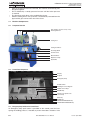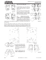
1
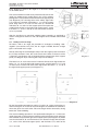
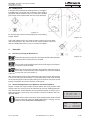
User’s Manual
Butt-welding Machine for Workshop Applications
CNC 2000 ECO-w
HÜRNER SCHWEISSTECHNIK GmbH
Nieder-Ohmener Str. 2
D - 35325 Mücke
Tel.
+49 (0)6401 91 27 0
Fax
+49 (0)6401 91 27 39
E-Mail [email protected]
Web
http://www.huerner-st.de
Version April 2005
HÜRNER Schweisstechnik GmbH
Nieder-Ohmener Str.
35325 Mücke, Germany
Contents
1
2
2.1
2.2
2.5
2.4
2.5
2.6
2.7
3
3.1
3.1.1
3.1.2
3.1.3
3.2
3.3
3.3.1
3.3.2
3.3.3
3.3.4
3.3.5
4
4.1
4.2
5.10
4.4
4.4.1
4.4.2
4.4.3
4.4.4
4.4.5
4.4.6
4.4.7
4.4.8
4.4.9
4.4.10
4.5
5
5.1
6
Introduction .......................................................................................................... 5
Safety Instructions................................................................................................ 5
The User’s Manual ............................................................................................... 5
Explaining Icons ................................................................................................... 5
Safety Messages.................................................................................................. 5
Warranty ............................................................................................................... 6
Service and Repair............................................................................................... 7
Transport / Storage / Shipment ............................................................................ 7
Identifying the Machine ........................................................................................ 7
Understanding the Machine ................................................................................. 7
Machine Components .......................................................................................... 8
Component Overview........................................................................................... 8
Control Panel Components .................................................................................. 8
Emergency Stop Switch on the Control Panel ..................................................... 8
Technical Specs ................................................................................................... 9
Preparing to Weld Pipes and Fittings ................................................................... 9
Welding Elbows from Pipe Segments .................................................................. 9
Welding Ys with 60° Angle ................................................................................. 10
Welding Ys with 45° Angle ................................................................................. 11
Welding right-angles Tees .................................................................................. 12
Welding Crosses ................................................................................................ 13
Operation............................................................................................................ 13
Check-out, Turning the Machine On ................................................................... 13
Default Configuration of the Machine and the Set-up Menu .............................. 13
Entering Applicable Welding Parameters ........................................................... 15
Welding Process ................................................................................................ 15
Facing the Pipe Ends ......................................................................................... 16
Checking Pipe Alignment ................................................................................... 16
Changing Welding Parameters........................................................................... 16
Inserting and Monitoring the Heating Element ................................................... 16
Bead Build-up Phase ......................................................................................... 17
Heat Soaking Phase .......................................................................................... 17
Change-over Phase ........................................................................................... 17
Joining Phase..................................................................................................... 17
Cooling Phase .................................................................................................... 17
End of Welding ................................................................................................... 17
Welding Aborted................................................................................................. 18
Printing Welding Reports.................................................................................... 18
Printing, the Print Menu...................................................................................... 19
Service and Repair Contact ............................................................................... 19
Version April 2005
CNC 2000 ECO-w User’s Manual
EN
3
HÜRNER Schweisstechnik GmbH
Nieder-Ohmener Str.
35325 Mücke, Germany
4 EN
CNC 2000 ECO-w User’s Manual
Version April 2005
HÜRNER Schweisstechnik GmbH
Nieder-Ohmener Str.
35325 Mücke, Germany
1
Introduction
Dear Customer:
Thank you very much for purchasing our product. We are confident that it will
meet your expectations and hope that it will contribute to your professional
success.
The development, manufacture, and check of the heating element butt-welding
machine has been guided by our concern to offer a device characterized by
superior operation safety and user-friendliness. The device was manufactured
and checked according to state-of-the-art technology and widely recognized
safety regulations.
To ensure maximum operation safety, please conform to the appropriate messages in this booklet and the regulations for the prevention of accidents.
This manual is applicable to the following machines:
CNC 2000 ECO-w
Thank you.
2
Safety Instructions
This User’s Manual contains important instructions for operating safely the heating element butt-welding machines Hürner CNC 2000 ECO-w. Every person
who operates the machines will first have to read this Manual.
2.1
The User’s Manual
The User’s Manual is presented according to sections, which explain the different functions of the machines. All rights, in particular the right to copy and
distribute as well as to translate, are reserved. The copy or reproduction (in
print or electronic form) is subject to the prior written authorization by HÜRNER
Schweisstechnik, Mücke, Germany.
2.2
Explaining Icons
The following expressions and icons are used in this User’s Manual to refer to
safety-related issues:
Caution
This icon indicates that non-compliance may result in a hazardous
situation that possibly causes bodily injury or material damage.
This icon indicates important messages related to the correct use
of the machine. Non-compliance may cause problems of operation
Important and damage to the machine.
This icon indicates tips and useful information for using the machine
more efficiently and more economically.
Info
2.5
Safety Messages
Protect the power supply cord and the pressure lines from cutting edges. Have
an authorized service shop replace damaged cables or lines immediately.
• The device may be operated and serviced exclusively by authorized staff
who have been trained on it.
Version April 2005
CNC 2000 ECO-w User’s Manual
EN
5
HÜRNER Schweisstechnik GmbH
Nieder-Ohmener Str.
35325 Mücke, Germany
•
•
The machine may be operated only when observed.
Before operating the machine, always check for damaged parts and have
them repair or replace by an authorized service shop as needed.
The protective caps on the interface and the pressure lines have to be in
place during transport so as to prevent contaminants and humidity from
entering the machine.
EVU wiring regulations, VDE provisions, DIN / CE regulations, and national
laws will have to be respected.
Without prior authorization by the manufacturer, no modifications may be
made to the device.
•
•
•
Parts Under Power
After opening the machine or removing the cover, parts of it are
accessible that may be under power. The device may be opened
Caution exclusively by an authorized service shop.
Pipe Facing Tool
Start the pipe facing tool only when it is in its working position; protect
the facing surfaces from dirt and damage.
Caution It is forbidden to remove shaving from the machine while the facing
process is still running. Make sure nobody is present in this danger
zone.
Heating Plate
When working with the machine, be extremely cautious while the
heating plate is used. Since the heating plate presents a temperaCaution ture of more than 200°C during the welding process, it is absolutely
necessary that operators wear suitable protective gloves. Please note
that the heating plate will remain hot for a while after it was turned
off.
Danger of Bruises and Injury
Do not remain in the danger zone while the machine opens or closes
and be sure not to have you arms or hands between the moving and
Caution the fixed trolley of the machine.
Acceptable Work Conditions
The work zone has to be clean and has to have proper lighting. It
is dangerous to operate in a humid environment or close to inflamCaution mable liquids. In regard of this, acceptable work conditions have to
be ensured (e.g., sufficient distance between the machine and other
functional areas of the workshop).
Info
2.4
User’s Manual
The User’s Manual has to be available at any time on the site where
the machine is used. If the User’s Manual should come to be incomplete or illegible replace it without delay. Feel free to contact us for
assistance.
Warranty
Warranty claims may be raised only if the conditions for warranty given in the
General Terms and Conditions of Sale and Shipment obtain. Furthermore, the
conditions contained in the User’s Manual have to obtain.
6 EN
CNC 2000 ECO-w User’s Manual
Version April 2005
HÜRNER Schweisstechnik GmbH
Nieder-Ohmener Str.
35325 Mücke, Germany
2.5
Service and Repair
As the machine is used in applications that are sensitive to safety considerations,
it may be serviced and repaired only on our premises or by subcontractors
and partners who have been specifically trained and authorized by us. Thus,
constantly high standards of operation quality and safety are maintained.
Info
2.6
Non-compliance with this provision will dispense the manufacturer
from any warranty and liability claims for the machine and any consequential damage.
Transport / Storage / Shipment
The machine is shipped on a palette. When loading or unloading the machine,
ensure it is not tipped excessively. During transport, the pipe facing tool and the
heating element have to be in the working position and to be secured properly
in order to prevent them from tilting up.
Stumpfschweißmaschine
2.7
Identifying the Machine
Each machine is identified by a name plate. It shows the machine model (“Typ”),
the serial number (“Maschinennr.”), and the manufacturer. The first two digits
of the serial number represent the year of manufacture.
3
Typ
CNC 2000 ECO-w
Maschinennr. 05441019
Hürner Schweisstechnik
Nieder-Ohmener Str.
D - 35325 Mücke
CE
Tel. +49 6401 9127 0
Understanding the Machine
The machine is a butt-welding machine for plastics, which has basically three
functions:
• Controlling the welding process;
• Monitoring all the relevant parameters during the welding process;
• Generating a report summarizing the welding process.
The machine can be used both as on-site and as in-shop installation. Upon
entering the type of plastic, the pipe diameter, and the wall thickness, the
machine calculates all the parameters that are critical for the welding process,
taking into account the applicable national welding standards (DVS, INSTA).
The entire welding process is automatically controlled, monitored, and saved
to a report. The saved welding data can subsequently be transferred directly
to a printer or to a PC with DataWork / DataWork GIS installed.
The pipe and traceability data needed can be entered using both the film-protected alphanumeric keypad and a barcode scanning wand.
For various applications, the machine can be specifically configured in the
Configuration Menu (see section 4.2 “Configuring the Machine”).
The welder performs the welding process in the following manner:
• Pipes are clamped into the frame; if welding elbows, Tees or Ys only after
cutting the pipes for construction.
• Pipe ends are worked using the pipe facing tool.
• Pipe alignment is checked following the information on the display.
• The heating element is inserted after cleaning it and checking the temperature.
• After the heating element was inserted, the pipes close in automatically
at the predefined build-up pressure.
• During the build-up phase the weld bead builds up.
• The machine then moves on automatically to the heat-soaking phase.
• After the heat-soaking phase, the machine automatically moves the trolleys
apart and the welder can remove the heating element.
Version April 2005
CNC 2000 ECO-w User’s Manual
EN
7
HÜRNER Schweisstechnik GmbH
Nieder-Ohmener Str.
35325 Mücke, Germany
•
•
•
•
3.1
After the heating element was removed, the machine automatically joins
the pipes together.
This is followed by a steady pressure increase until the fusion pressure
is reached.
The pipe then cools down at the predefined pressure.
After the cooling time is over, pressure is automatically removed from the
pipe and the pipe can be taken out of the frame.
Machine Components
3.1.1 Component Overview
Pipe clamps (standard clamps shown)
Heating Element
Facing Tool
Facing Tool Motor
Scanning Wand
Control Panel
Machine Base
Operation Lamp
Hydraulics
3.1.2 Control Panel Components
Display
Keypad
Emergency Stop
On/Off Switch
Welding Process Diagram
MENU / Arrow Keys
ENTER Key
Interface (for printer / PC
connection)
ESC Key
OPEN Key
REDUCE PRESSURE Key
INCREASE PRESSURE Key
3.1.3 Emergency Stop Switch on the Control Panel
An Emergency Stop push button is provided on the control panel for interrupting the welding process, if needed, to prevent hazardous situations. If the
8 EN
CNC 2000 ECO-w User’s Manual
Version April 2005
HÜRNER Schweisstechnik GmbH
Nieder-Ohmener Str.
35325 Mücke, Germany
Emergency Stop button is pressed, it disables the power supply to the facing
tool, the heating element, and the hydraulics. Power is further supplied to the
micro-controller board (the display screen keeps working).
When it was pressed, the Emergency Stop push button remains
locked. When the hazard is cleared, the button has to be unlocked
Important by turning it clockwise. It is also possible to move the trolley on the
frame manually.
3.2
Technical Specs
Hürner CNC 2000 ECO-w
Power Characteristics
Voltage
Frequency
Total Rated Power
Heating Element
Facing Tool
Hydraulics
230 V
50 Hz
5.5 kW, 30 A
3.7 kW
1.5 kW
0.74 kW
Protection
Heating Element
Facing Tool
Hydraulics
IP54
IP44
IP44
Operating Range
90 - 315 mm
Hydraulic Characteristics
Operating Pressure max.
Cylinder
Ambient Temperature
Hydraulic Oil
110 bar
6.47 m²
–5°C bis +50°C
HLP 32
Dimesions and Weight
Total Machine Dimensions
Weight
Maximum Trolley Stroke
3.3
1220 x 900 x 1500 mm
250 kg
210 mm
Preparing to Weld Pipes and Fittings
Depending on the type of welding operation, the standard clamps mounted
on the trolleys of the butt-welding machine may have to be replaced by Tee
elements or Y elements.
3.3.1 Welding Elbows from Pipe Segments
Using the standard pipe clamps, it is possible to weld elbows of up to 45° from
segments of pipe. The standard clamps are secured to the support panel on
the trolley of the machine using bolts G, D, and E (see Diagram 1).
To weld an elbow from segments, loosen bolts G, D, and E and tip the clamp
fronts toward each other around the pivoting point G. Bolts D and E will remain
in the slots prepared for this operation. To place the clamps in the correct poA
B
C
D
E
F
G
Fixation Bolts of the Support Panel
Fixation Bolts of the Support Panel
Support Panel
Fixation Bolts of the Pipe Clamp
Fixation Bolts of the Pipe Clamp
Angle Scale
Fixation Bolts of the Pipe Clamp
(pivoting point)
Diagram 1
Version April 2005
CNC 2000 ECO-w User’s Manual
EN
9
HÜRNER Schweisstechnik GmbH
Nieder-Ohmener Str.
35325 Mücke, Germany
sition for the intended angle, use the
angle scale F for orientation.
To weld elbows up to 30° place D
and E as shown in Diagram 2, to weld
elbows larger than 30°, as shown in
Diagram 3.
Diagram 2
After the machine was prepared, welding proper proceeds as explained in
section 4. Diagram 4 shows an elbow
welded from several segments of pipe
with several welding operations.
3.3.2
Welding Ys with a 60° Angle
To weld Ys, replace the standard pipe
clamps with the Y clamp elements.
Remove bolts G, D, and E and take the
standard clamps from the the machine
Diagram 3
trolleys. This allows free access to the
support panels (see Diagram 5). Welding a Y will require that two welds will
be performed.
Diagram 4
Start by welding the 60° angle in the Y. To do so, place Y element Z on the
left-hand support panel and Y element W on the right-hand support panel.
Make sure that for securing the Y clamp element to the trolley, holes A, F, and
H of the base (see Diagram 10) of element Z align with holes 6, 8, and 13 of
Diagram 5
the left-hand support panel.
Holes A, F, and H of the base
of element W have to align
with holes 4, 8, and 13 of the
right-hand support panel (see
Diagram 6).
After the machine was prepared, welding proper proceeds as explained in sec-
Diagram 6
Diagram 7
10 EN
CNC 2000 ECO-w User’s Manual
Version April 2005
HÜRNER Schweisstechnik GmbH
Nieder-Ohmener Str.
35325 Mücke, Germany
tion 4. Diagram 7 shows a 60° angle in a Y that was welded
as described above.
The second weld that needs to be performed will connect the
angle just welded to the straight pipe in the Y. This requires
placing both Y clamp elements onto the left-hand support panel
(see Digram 8). For securing them to the trolley, align holes
C, D, and G of Y element Z with holes 1, 17, 3 of the support
panel. Align holes C, D, and G of the base of Y element W
with holes 10, 14, and 11 of the support panel. Then place the
standard pipe clamp on the right-hand support panel, secure
it to holes 5, 7, and 11, and tip its front toward the centerline
as far as possible.
Diagram 8
After the machine was prepared, welding proper proceeds as explained in
section 4. Diagram 9 shows a Y with a 60° angle that was welded as described
above.
3.3.3 Welding Ys with a 45° Angle
To weld a Y with a 45° angle, the procedure is analogous to welding a 60°angled Y (see section 3.3.2): First, the 45° angle is welded, then the straight
pipe is connected to this angle.
Start by removing the standard pipe clamps from the support panel and mount
the Y clamp elements. Here, too, make sure that the holes in the base of the
Y elements (see Diagram 10) are aligned with the proper holes of the support
panel (see Diagram 5) for securing the clamps to the trolleys.
Diagram 9
The holes B, A, H, and I of the base of Y element Z have to be aligned with the
holes 4, 5, 12, 15 of the left-hand support panel, and the holes B, A, H, and
I of the base of Y element W have to be aligned with the holes 1, 2, 12, 10 of
the right-hand support panel (see Diagram 11).
Diagram 10
For the first welding operation for making a Y with a 45° angle, cut the pipes as
shown in Diagram 12. Leave 10 mm more length than needed at the centerline,
where the pipes face each other. This extra length will be removed by facing
before the second welding.
The second welding operation is also performed analogous to a Y with a 60°
angle: place both Y clamp elements onto the left-hand support panel and place
one standard clamp onto the right-hand support panel (see Diagram 13). Make
sure that the holes E, B, and A of the base of Y element Z align with the holes
4, 2, and 7 of the left-hand support panel, and the holes A, B, and E of the
Version April 2005
CNC 2000 ECO-w User’s Manual
EN
11
HÜRNER Schweisstechnik GmbH
Nieder-Ohmener Str.
35325 Mücke, Germany
base of Y elements W align with the holes 9, 6, and 12 of
the left-hand support panel. The standard pipe clamp for
welding elbows has to be placed onto the right-hand support panel in such a way that the angle scale shows 45°
(see Diagram 1).
After the machine was prepared in both cases, the welding
operations proper proceed as explained in section 4. Diagram 14 shows a Y with a 45° angle welded as described
above, after the first and after the second welding
operation.
Diagram 11
Diagram 12
3.3.4 Welding right-angles Tees
To weld Tees, replace the standard pipe clamps
with the Tee elements. Remove bolts G, D, and
E and take the standard clamps from the the
machine trolleys. This allows free access
to the support panels (see Diagram 5).
Welding a Tee will require that two welds
will be performed.
Diagram 13
Start the operation by welding the 90°
elbow. To do so, place the Tee element
intended for the left-hand side on the lefthand support panel and make sure that
for securing the Tee clamp element to the
trolley, holes A, B, C, and D of the base
of the Tee element (see Diagram 15) align
with holes 4, 5, 12, and 15 of the left-hand
support panel. Holes A, B, C, and D of the
base of the Tee element intended for the
right-hand side have to align with holes 1,
2, 10, and 12 of the right-hand support
panel.
After the machine was prepared, welding
proper proceeds as explained in section 4.
Diagram 17 shows a 90° elbow, first welding for a Tee, that was welded as described
above.
After the first welding operation, the 90° elbow is cut,
placed into the Tee clamp
element and connected to
the straight pipe by using
the same welding procedure. Diagram 18 shows a
Tee welded as described
above, after the second
welding operation.
Diagram 14
12 EN
Diagram 15
CNC 2000 ECO-w User’s Manual
Version April 2005
HÜRNER Schweisstechnik GmbH
Nieder-Ohmener Str.
35325 Mücke, Germany
3.3.5 Welding Crosses
In principle, the procedure for welding crosses is analogous
to welding Tees (see section 3.3.4). However, three welding
operations will be needed in this case. After the standard
pipe clamps were replaced with the Tee clamp elements,
Diagram 17
the first two steps of this kind of welding consist of welding
two 90° elbows.
Diagram 16
Then, both elbows will be cut along the outer angle to face each other
and will be placed in this state into the Tee clamp elements. The third
and last welding then forms a cross out of the two elbows.
4
Operation
4.1
Check-out, Turning the Machine On
Diagram 18
Important
Important
Before the control unit is turned on, check the oil level of the hydraulics
and fill up HLP 32 hydraulic oil as needed.
The surfaces of the heating plate have to be free of grease and clean,
or they have to be cleaned.
Make sure all connectors are tight in their sockets and make sure that
the machine is operated only if the conditions for safe and intended
Important use are met (see also section 2).
After connecting the power supply cable to the mains power supply, the machine
is turned on using the On/Off switch. It is possible that the main switch located
on the mounting box inside the right-hand leg of the machine has to be turned
into the On position to have the machine under power.
4.2
Default Configuration of the Machine and the Set-up Menu
Display 2 shows the report number number (before the slash) and the weld
number (after the slash) that will be attributed to the next welding operation.
The weld number, which identifies the incremented number of weld, e.g. of a
given commission, shows only if this function has been enabled in the Configuration Menu.
Info
To bring the machine in the open or the closed position (trolley moved
apart or closed in) when no welding procedure is running, use the
OPEN and the INCREASE PRESSURE keys.
xxxxxx HUERNER xxxxx
x CNC 2000 ECO-W x
x Version 1.05PD x
xxxxxxxxxxxxxxxxxxxx
Display 1
Next Welding
Time
: 10:32
Date
: 08.03.05
Prot. No. :0014/0005
Display 2
Version April 2005
CNC 2000 ECO-w User’s Manual
EN
13
HÜRNER Schweisstechnik GmbH
Nieder-Ohmener Str.
35325 Mücke, Germany
The Configuration Menu is accessible by pressing the MENU key when Display 2 shows on the screen.
When the operator presses the MENU key, the screen asks to enter a selection
code (see Display 3). This is an access code that authorizes the operator to
select and change machine parameters in the appropriate configuration menus.
The selection code can be entered using both the keypad and the scanning
wand to read the operator code.
Enter Select Code
++++++
Display 3
After entering an incorrect code three times, the machine returns CONFIGURATION SELECTION CODE:
automatically to the ready-to-weld screen (Display 2). If the access
415311
code for selecting and changing values that was entered is correct,
Important the Configuration Menu shows on the screen, as in Display 4.
In the Configuration Menu use the UP and DOWN arrow keys to select a specific configuration option. The option can then be set to On or Off using the
RIGHT arrow key. The –M– displayed for the Set Clock, Choose Language,
and Guideline options indicates that a sub-menu can be accessed by pressing
the MENU key.
REPORTS
>Commissions No. on
Welder Code
on
Memory Contr.
on
When you press the ENTER key, the settings will be saved and applied. Press ESC to quit the configuration menu without saving any
Important modifications.
Display 4
The Configuration Menu contains the options listed in the table below.
Description
Setting
Data to be entered
Commission Number
ON / OFF
To be entered before every welding, 32 alphanumeric
characters
Welder ID Code
ON / OFF
To be entered before every welding, ISO welder identification
code
Memory Control
ON / OFF
if ON: Machine stops when the memory is full
if OFF: Machine overwrites the oldest report when the memory
is full
Weld Number
ON / OFF
To be entered before the first welding, machine increments by 1
for each subsequent weld
Additional Data
ON / OFF
To be entered before every welding, 20 alphanumeric
characters
Monitor Ambient
Temperature
ON / OFF
if ON: Ambient temperature will be checked when machine is
turned on
if OFF: No check of ambient temperature
If the ambient temperature is below 0°C, no welding process
should be started, or suitable steps should be taken.
Manual Input
ON / OFF
if ON: It is possible to change the welding parameters manually;
if OFF: manual change of welding parameters impossible
Automode
ON / OFF
if ON: Build-up time included in the control software is used, the
build-up phase will be ended automatically;
if OFF: the build-up phase has to be ended manually by
pressing the ENTER key
Guideline
—M—
Selecting the welding standard (sub-menu)
Set Clock
—M—
Setting the time of day and date (sub-menu)
Choose Language
—M—
Setting the display/printer language (sub-menu)
14 EN
CNC 2000 ECO-w User’s Manual
Version April 2005
HÜRNER Schweisstechnik GmbH
Nieder-Ohmener Str.
35325 Mücke, Germany
5.10 Entering Applicable Welding Parameters
After having entered – if enabled – the traceability data, such as Commission
Number, Welder ID Code, etc., you can start entering the welding data proper,
or you can use the parameters from the preceding weld.
After it was turned on, the machine goes on from Display 2 to Display 5 when
you press the ENTER key. To keep the all displayed welding parameters for the
following welding, press the ENTER key, the welding will start immediately.
If data have to be changed for the next welding, press ESC. The first step
consists of selecting the appropriate pipe material using the UP/DOWN cursor
keys (see Display 6). Use the ENTER key to confirm you selection of the pipe
material. The machine goes on automatically to the next menu item, entering
the pipe dimesions.
This screen (see Display 7) asks the welder to enter the diameter, the wall
thickness or the standard dimension ratio (SDR) of the pipe that is going to
be welded. This is done moving the cursor character by character and into the
next line using the RIGHT arrow key. To be able to enter the SDR, first press
the DOWN arrow key when they cursor is in the Wall thickness line. To apply
the values entered, press the ENTER key.
Finally, the type of welding is also part of the welding parameters (see Display 9).
Here, too, use the UP and DOWN arrow keys to select the kind of welding that
is going to be performed, and confirm your selection by pressing the ENTER
key. The available options are Straight welding, Elbow welding, T Element,
Y 45° Element, Y 60° Element, and Cross.
If a Y element welding is selected in this menu, the welder has to specify
furthermore if the welding is the first or the second for making this Y (see
Display 10).
If a elbow welded from pipe segments is selected, the angle the elbow is going
to have has to be entered (see Display 11).
When entering the angle to be welded, enter the full angle in degrees
that the elbow should have; do not enter half the angle value. The
standard pipe clamps of the machine, too, have to be aligned with
Important the full angle value on the scale on the support panels rather than
with half the intended value.
Pipe material: PE80
Pipe diameter:0250mm
Wallthickness:22.7mm
Straight welding
Display 5
SELECT PIPE MATERIAL
>PE80
PE100
PP
Display 6
ENTER PIPE DIMENSION
Pipe diameter:0250mm
Wallthickness:22.7mm
Display 7
ENTER PIPE DIMENSION
Pipe diameter:0250mm
SDR
: 9.0
Display 8
SELECT WELDING TYPE
>Straight Welding
Elbow Welding
T Element
Display 9
Y 45° ELEMENT
>1. Welding
2. Welding
Display 10
ENTER ANGLE
Angle
See section 3.3 for a detailed overview on how to prepare the machine
for welding elbows, Tees, Ys and crosses.
: 30 °
Display 11
Info
Using the entered parameters on pipe material, pipe dimension, and type of
welding, the machine calculates the required pressures, welding phase duration, and the temperature of the heating element. After you have entered the
parameters, they are displayed once again for verification. The data shown can
still be changed by pressing the UP arrow key to go back one step at a time
and access the screen in question. Confirm these values by pressing ENTER
in order to go on to the welding process proper.
4.4
Welding Process
Before you start welding, the machine has to be prepared for the intended type
of welding. If necessary, the standard pipe clamps have to be adjusted to the
correct angle scale on the support panels, or they have to be replaced with the
Tee element or Y elements. See section 3.3 to learn how the special elements
are placed onto the support panels and adjusted.
Version April 2005
CNC 2000 ECO-w User’s Manual
EN
15
HÜRNER Schweisstechnik GmbH
Nieder-Ohmener Str.
35325 Mücke, Germany
After the machine was prepared, the welding parameters for the following weld
were entered (see section 4.3) and confirmed by pressing the ENTER key, the
machine starts the welding process by facing the pipe ends (see Display 12).
4.4.1 Facing the Pipe Ends
To ensure the pipe ends are level, insert the pipe facing tool into the machine.
Clicking its handle into place in its working position turns it on automatically. The
machine will then bring the pipes to the facing tool at the predefined pressure.
Use the INCREASE PRESSURE and REDUCE PRESSURE keys to adjust
the pressure during facing manually.
Facing pipe ends
Display 12
Pipe facing should continue until shaving forms a continuous blade that rolls
twice or three times around the pipe ends, so the butts are level. Facing is
stopped by pressing the ENTER key. The machine automatically retracts the
pipes.
If you discover after the facing process that the butts are still not level, start
over, open the machine completely, insert the facing tool, thereby launching
pipe facing automatically. When facing is properly done, pipe alignment has
to be checked.
4.4.2 Checking Pipe Alignment
Press the ENTER key to have the machine place the pipes together automatically. On the screen (Display 13), the maximum acceptable alignment gap between the pipes is shown. If the pipes align properly, this has to be confirmed
by pressing the ENTER key.
Check pipe alignment
Max. gap
: 2.5mm
Display 13
If the gap is too large, re-adjust the pipes in the clamps and start the facing
process again as needed. To do so, place the machine in the open position first
using the OPEN key. Then insert the facing tool, launching the facing process by
clicking the handle into place in its working position. You can abort the welding
process by pressing ESC.
4.4.3 Changing Welding Parameters
IWhen pipe alignment was checked, the machine moves on automatically to
Display 14 if the Manual Input option is enabled in the Configuration Menu. In
Display 14, the welder can keep the welding parameters from the last weld by
pressing the ENTER key or he can adjust them to his specific purposes by
pressing the ESC key (see Display 15).
Do you want to use
data of previous
welding?
ESC
<¬
Display 14
If the parameters for the next welding process are entered manually, the UP
and DOWN arrow keys are used to select the line the is to be changed, and the
new value is typed on the keypad. The parameters are saved and applied by
pressing the ENTER key; the machine moves on from Display 15 to Display 16
or from Display 16 back to the welding process.
Heating pr.:030.5bar
Heatsoakpr.:010.5bar
Heat soak :0120 s
Change-over:0005 s
The parameters set manually are kept in memory when the machine
is turned off. Only the pressure values are calculated individually for
each welding process. If the pipe dimensions change, all parameters
Important have to be set once again. The machine recognizes the change of
dimension and leads the operator directly to the menu that allows
changing the parameters.
Cool. time :0900 s
Pr. build-up:0010 s
Heat. temp. :0223 °C
4.4.4 Inserting and Monitoring the Heating Element
The machine controls and monitors constantly the temperature of the heating
element. If the temperature is not within the tolerance thresholds, the machine
shows an error message to this effect in the first line of the display. Furthermore,
the upper and lower thresholds of the tolerance range are indicated in the fourth
line along with the current actual temperature (see Display 17).
Display 15
Display 16
Plate temp. too low
222°C< 210 °C <232°C
Display 17
16 EN
CNC 2000 ECO-w User’s Manual
Version April 2005
HÜRNER Schweisstechnik GmbH
Nieder-Ohmener Str.
35325 Mücke, Germany
As soon as the nominal temperature is reached, Display 18 shows.
Put in heat. plate
By inserting the heating element, you make the machine move on to the Buildup Phase. At this time, the pipes are placed together automatically and the
calculated pressure during bead build-up is applied.
222°C
221°C
4.4.5 Bead Build-up Phase
IDuring the Build-up Phase LED 1 flashes to indicate the progress of the welding
process. As soon as the build-up pressure is achieved, as shown in Display 19,
the display indicates both the maximum bead height and the time so far used
for build-up. During this phase, the build-up pressure and the heating element
temperature are constantly monitored.
When the bead height indicated on the display is reached, the operator has
to press the ENTER key to terminate the Build-up Phase. The machine then
continues automatically to the Heat Soaking Phase.
NOM.
ACT.
16.5bar
0.5bar
Display 18
Bead height
:2.0mm
Bead buildtime:68 s
230°C NOM. 16.5bar
229°C ACT.
2.5bar
Display 19
As long as the nominal pressure of the Heat Soaking Phase is not reached
yet, LED 2 flashes while LED 1 is steadily lit. The machine reduces pressure
automatically.
If the Automode option is enabled in the Configuration Menu, the
Build-up Phase will be terminated automatically at the end of the
bead build-up time included in the control software. If this is not the
Important case, the end of the Build-up Phase has to confirmed manually.
4.4.6 Heat Soaking Phase
The time for soaking heat is displayed as a countdown showing the remaining
seconds (see Display 20). A signal is audible during the final 10 seconds of
heat soak immediately before the change-over. During the Heat Soaking Phase
LED 3 flashes; LED 1 and LED 2 are steadily lit.
During this phase, the pressure applied while the pipes soak the heat from the
plate and the plate temperature are constantly monitored and controlled.
4.4.7 Change-over Phase
After the full heat soaking time, the pipes retract automatically. The heating
element has to be removed as fast as possible (see Display 21). During the
Change-over Phase LED 4 flashes; all previous LEDs are steadily lit.
The machine then places the pipes automatically together again.
4.4.8 Joining Phase
In the Joining Phase the machine increases pressure in accordance with the
pressure ramp calculated for the weld (see Display 22). During this phase LED
5 flashes; all previous LEDs are steadily lit.
4.4.9 Cooling Phase
When the full joining pressure is reached, the machine moves on automatically
to the Cooling Phase (see Display 23). The cooling-down is displayed as a
countdown. During cooling, the joining pressure applied is constantly monitored.
During this phase, LED 6 flashes, all the previous LEDs are steadily lit
4.4.10 End of Welding
A double buzz indicates that the cooling time has ended. Furthermore, the
green LED is steadily lit to indicate a successful welding process. Confirm the
HEAT SOAK PHASE
Heatsoak time:168 s
230°C NOM. 16.2bar
229°C ACT.
3.2bar
Display 20
Remove plate
Change-over
: 8 s
230°C NOM. 16.5bar
229°C ACT.
3.5bar
Display 21
JOINING PHASE
230°C
229°C
NOM.
ACT.
16.5bar
3.5bar
Display 22
COOLING PHASE
Cooling time over
229°C
ACT.
0.0bar
Display 23
Version April 2005
CNC 2000 ECO-w User’s Manual
EN
17
HÜRNER Schweisstechnik GmbH
Nieder-Ohmener Str.
35325 Mücke, Germany
end of welding be pressing the ENTER key. Pressure will then be switched off
from the machine.
4.5
Welding Aborted
All welding-relevant data are constantly monitored while the welding process
is running. If one or more of the parameters are out of tolerance and cannot
be controlled to adjust, the welding process is aborted after a given period of
time.
WELDING STOPPED
Error Build-up pres.
229°C
ACT.
1.5bar
Display 24
In these cases the error that made the welding process abort is displayed (see
Display 25). In addition, the corresponding LED flashes. The error message
has to be confirmed by pressing the ENTER key.
The errors listed in the following table are recognized and displayed on the
screen.
Type of Error
Description
a. Data Input
Input Error
Erroneous parameter input
b. System
Clock Defective
Internal clock of the machine is defective; use the
Cnfiguration Menu to reset the clock
Pressure Sensor defective
Pressure sensor defective
Heating Sensor defective
Heating element not connected, check connector/socket
Temperature Sensor defective Ambient temperature sensor is defective
c. Welding Process
Temperature low
Heating element temperature will be increased automatically
Temperature high
Heating element temperature will be reduced automatically
Error Changeover
It took too long to retract the mirror and bring the pipes to
joining; welding will have to be repeated
Ambient Temperature high
Ambient temperature outside the range from 0°C to 50°C
Ambient Temperature low
Ambient temperature outside the range from 0°C to 50°C
Error Drag Pressure
Impossible to determine the drag pressure; maybe pipes will
have to be clamped once again
Error Build-up Pressure
Calculated maximum pressure too high; impossible to start
welding; maybe pipes will have to be clamped once again
Error Heat Soak Pressure
Heat soaking pressure too high; impossible to re-adjust
Error Joining Pressure
Joining pressure too high or too low; impossible to re-adjust
Cooling Stopped
Operator has stopped the cooling time by pressing the ESC
key
Power Supply Failure
In the course of the last welding a power supply failure
occurred; welding has to be repeated
Error Plate Temperature
Plate temperature is out of tolerance; impossible to re-adjust
the temperature; maybe the ambient temperature was too
low
5
Printing Welding Reports
The machine is equipped with a dual interface that gives you the opportunity
to connect a common PC printer directly to it or to export the data via a RS232
cable to a PC with DataWork or DataWork GIS installed.
18 EN
CNC 2000 ECO-w User’s Manual
Version April 2005
HÜRNER Schweisstechnik GmbH
Nieder-Ohmener Str.
35325 Mücke, Germany
Technical Specs of the Interface:
• Parallel + Centronics
• Serial
+ RS232
Baud Rate
Data Bits
Stop Bits
Transfer Protocol
5.1
19200 Baud
8
2
X_ON / X_OFF
Printing, the Print Menu
When a data communication cable (Centronics, Serial) is connected, the machine displays the Print Menu. Data will be sent according to the selection to
the a printer or to a PC.
Use the UP/DOWN arrow keys to switch between Print all Protocols and Print
Commission No. and press ENTER to confirm your selection of a print mode.
The Print all Protocols mode causes all the report protocols stored in system
memory to be printed off. The Print Commission No. mode leads the operator
automatically to the next screen where the commission number to be printed
is selected (see Display 26).
If the Print Commission No. mode is selected in the Print Menu, the first available commission number is displayed. Use the UP/DOWN arrow keys to display
one after the other the commission numbers stored in system memory. Select
one of them and press ENTER to send the data from this commission only to
the printer or PC.
If the machine displays a “Printer not Ready” error message after you pressed
ENTER, the printer has to be switched to on-line mode. Check for potentially
damaged connections from the machine to the printer or the PC.
xxx PRINT MENU xxx
>Print all protocols
Print commission no
Display 25
Print commission no
++++++++++++++++++++
++++++++++++
Display 26
If you transfer the data to a PC, make sure to select the correct baud rate and
interface type.
Info
6
Depending on the printer used, make sure Auto Carriage Return
and/or Auto Line Feed are enabled, if necessary, so as to print the
reporting protocol in the correct format.
Service and Repair Contact
Hürner Schweisstechnik
Nieder-Ohmener Str.
35325 Mücke, Germany
Tel.: +49 (0)6401 9127 0
Fax: +49 (0)6401 9127 39
Web: www.huerner-st.de
Mail: [email protected]
Version April 2005
CNC 2000 ECO-w User’s Manual
EN
19
KONFORMITÄTSERKLÄRUNG
Declaration of Conformity
Déclaration de conformité
Wir / We / Nous
HÜRNER Schweißtechnik
Nieder-Ohmener Str.
D-35325 Mücke-Atzenhain
erklären in alleiniger Verantwortung, dass das Produkt
declare under our sole responsibility that the product
déclarons sous notre seule responsabilité que le produit
CNC 2000 ECO-w
Heizelement-Stumpfschweißmaschine für die Verarbeitung von Kunststoffrohren und -formteilen
Heating element butt-welding machine for processing plastic pipes and fittings
Machine à souder bout-à-bout à élément chauffant pour l’assemblage des tubes et raccords en plastique,
auf die sich diese Erklärung bezieht, mit den folgenden Normen oder normativen Dokumenten
übereinstimmen
to which this declaration relates, are in conformity with the following standards or standardizing
documents
auxquels se réfère cette déclaration, sont conformes aux normes et documents de normalisation
suivants
CE-Konformität / CE Conformity / Conformité CE
EG Richtlinie 89/336 EWG
EG Niederspannungsrichtlinie 73/23 EWG
Andere Normen / Other Standards / Autres normes
EN 50081-1 Generic Emission Standard 03.93
EN 50082-1 Generic Immunity Standard 03.93
EN 60335-1 / IEC 335-1 1995
Bei einer nicht mit uns abgestimmten Änderung der Maschine oder einer Reparatur von Personen,
die nicht von uns im Hause geschult und autorisiert wurden, verliert diese Erklärung ihre Gültigkeit.
Any and all modifications of the device without our prior approval, and any repairs by persons who
were not trained and authorized by us, shall cause this declaration to become void.
En cas de modification apportée à l’appareil sans notre accord préable ainsi que de réparation
effectuée par des personnes non formées et agréées par non soins, cette déclaration deviendra
caduque.
Mücke-Atzenhain
den 01.04.2005
(Ort und Datum)
(Place and date)
(Lieu et date)
................................................................
(Hans Strasser)
Name und Unterschrift des Befugten / Leitung Fertigung
Name and signature of the authorized / Head of Manufacture
Nom et signature du responsable / Direction de Fabrication
.................................................................
(Dipl.Ing. Michael Lenz)
Name und Unterschrift des Befugten / Leitung Entwicklung
Name and signature of the authorized / Head of Development
Nom et signature du responsable / Direction de Développement