1
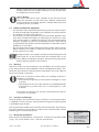
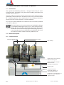
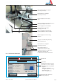
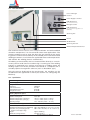
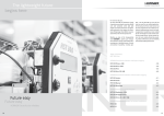
User’s Manual
Infrared Welding Machine
SP -S
P.O. Box 653 • 35 Green Street, Malden, MA 02148 • Tel: (800) 343-3618, (781) 321-5409
Fax: (800) 426-7058 • Website: www.asahi-america.com • Email: [email protected]
agru Kunststofftechnik GmbH
Ing.-Pesendorfer-Str. 31
4540 Bad Hall, Austria
Contents
1
2
2.1
2.2
2.3
2.4
2.5
2.6
2.7
3
3.1
3.2
3.2.1
3.2.2
3.2.3
3.2.4
3.3
4
4.1
4.2
4.3
4.4
4.5
4.6
4.6.1
4.6.2
4.6.3
4.6.4
4.6.5
4.6.6
4.6.7
4.6.8
4.7
5
5.1
5.2
5.3
6
6.1
6.2
7
8
Introduction........................................................................................................... 5
Safety Messages .................................................................................................. 5
The User's Manual ............................................................................................... 5
Explaining Icons ................................................................................................... 5
Safety Messages .................................................................................................. 6
Welder and Operator Obligations ......................................................................... 7
Warranty ............................................................................................................... 7
Transport and Storage .......................................................................................... 7
Identifying the Machine ........................................................................................ 7
Product Description and Principles of Operation ................................................. 8
Intended Use ........................................................................................................ 8
Machine Description ............................................................................................. 8
Component Overview ........................................................................................... 8
Touchscreen / Control Panel ................................................................................ 9
Ports and Switches............................................................................................. 10
Specifications ..................................................................................................... 10
Welding Process Overview ................................................................................ 11
Operation............................................................................................................ 12
Check-out, Turning on, Selecting the Display Language .................................... 12
Entering Traceability Data for the Joint ............................................................... 13
Configuring the Machine .................................................................................... 14
Changing Key Data of the Welding..................................................................... 15
Definition of Welding Parameters for Additional Materials.................................. 16
Welding Process ................................................................................................ 17
Facing the Pipe Butts ......................................................................................... 18
Checking Pipe Alignment ................................................................................... 19
Pre-heating the Pipe Butts and Inserting the Heating Element .......................... 19
Heat-Soaking Phase .......................................................................................... 20
Change-over Phase ........................................................................................... 20
Joining Phase ..................................................................................................... 20
Cooling Phase .................................................................................................... 20
End of Welding ................................................................................................... 20
Aborted Welding Process ................................................................................... 21
Printing and Transferring Welding Reports ......................................................... 22
The Print Menu and Printing/Transferring Reports ............................................. 22
Showing Reports in Memory, Reprinting Tags ................................................... 23
Deleting Reports from Memory .......................................................................... 23
System Data ....................................................................................................... 23
Setting the Date and the Time of Day ................................................................ 23
Enabling Automatic Heating ............................................................................... 24
Service and Repair............................................................................................. 24
Service and Repair Contact ............................................................................... 25
P.O. Box 653 • 35 Green Street, Malden, MA 02148 • Tel: (800) 343-3618, (781) 321-5409
Fax: (800) 426-7058 • Website: www.asahi-america.com • Email: [email protected]
Version June 2010
agru SP 250-S User’s Manual
EN
3
agru Kunststofftechnik GmbH
Ing.-Pesendorfer-Str. 31
4540 Bad Hall, Austria
The machine has to be operated exclusively with
a power supply line equipped with a protective
grounding conductor, as a power supply without
Caution this safety element may cause severe machine
damage. If the machine is operated through a
power supply without a grounding conductor,
this will void any and all warranty under which
the product may be.
4 EN
agru SP 250-S User’s Manual
Version June 2010
agru Kunststofftechnik GmbH
Ing.-Pesendorfer-Str. 31
4540 Bad Hall, Austria
1
Introduction
Dear Customer:
Thank you very much for purchasing our product. We are confident that
it will meet your expectations.
The development, manufacture, and check of the infrared welding machine
has been guided by our concern to offer a unit characterized by superior
operation safety and user-friendliness. The unit was manufactured and
checked according to state-of-the-art technology and widely recognized
safety regulations.
To ensure maximum operation safety, please conform to the appropriate
messages in this booklet and the regulations for the prevention of accidents. Carefully read the User’s Manual to avoid damage to the machine
or hardware in its environment as well as injury.
This manual is applicable to the following machines:
agru SP 250-S
Thank you.
2
Safety Messages
This User’s Manual contains important instructions for operating the infrared welding machine agru SP 250-S safely. Every person who operates
the machine will have to conform to the instructions of this manual.
The machine has been developed and checked with respect to welding
AGRU materials. For welding other makes, no experiential data are available and/or no liability or warranty can be assumed for the fitness and
the reliable operation of the machine.
2.1
The User's Manual
The User’s Manual is presented according to sections which explain the
different functions of the machine. All rights, in particular the right to
copy or reproduce (in print or electronic form) and distribute as well as
to translate, are reserved and subject to prior written authorization.
2.2
Explaining Icons
The following expressions and icons are used in this User’s Manual to
refer to safety-related issues:
Caution
This icon indicates that non-compliance may result in a hazardous situation that possibly causes bodily injury or material
damage.
This icon indicates important messages related to the correct
use of the machine. Non-compliance may cause problems of
Important operation and damage to the machine.
This icon indicates tips and useful information for using the
machine more efficiently and more economically.
Info
Version June 2010
agru SP 250-S User’s Manual
EN
5
agru Kunststofftechnik GmbH
Ing.-Pesendorfer-Str. 31
4540 Bad Hall, Austria
2.3
Safety Messages
Protect the power supply cord from cutting edges. Have an authorized
service shop replace damaged cables or lines immediately.
The machine has to be operated with a 400 V, 50/60 Hz power supply
with safety fuse or breaker of 32 A. If power is connected through a
power line manifold, the power supply has to feature an earth-leakage
circuit breaker.
The length of the power supply cord is 4 m (13 feet). The length of an
extension cable will preferably not exceed 10 m (30 feet).
Parts Under Power
After opening the machine or removing the cover, parts of it
are accessible that may be under power. The machine may be
Caution opened exclusively by an authorized service shop.
Pipe Facing Tool
Start the pipe facing tool only when it is in its working position.
When facing pipes, do not wear jewellery; if needed, wear a
Caution hair snood or net. It is forbidden to remove shaving from the
machine while the facing process is running. Make sure nobody
is present in this danger zone.
Heating Plate
When working with the machine, be extremely cautious while the
heating plate is operating. Since the heating plate and its guard
Caution present a very high temperature during the welding process,
it must not be operated if unobserved, and sufficient distance
has to be ensured to combustible materials in its surroundings.
Do not touch the heating plate or the heating plate guard.
Danger of Bruises and Injury
Do not remain in the danger zone while the machine opens or
closes and be sure not to have your hands between the moving
Caution and the fixed parts of the machine. The forces exercised by
the machine are so high that it will not be able to detect and
recognize parts of the body.
Acceptable Work Conditions
The work zone has to be clean and has to have proper lighting.
It is dangerous to operate in a humid environment or close to
Caution flammable liquids. In regard of this, acceptable work conditions have to be ensured (e.g., sufficient distance between the
machine and other functional areas of the workshop).
Power Supply Only through Line with Protective Grounding
Conductor
The machine has to be operated exclusively with a power supply
Important
line equipped with a protective grounding conductor, as a power
supply without this safety element may cause severe machine
damage. If the machine is operated through a power supply
without a grounding conductor, this will void any and all
warranty under which the product may be.
Power Only to Operational Machine
Power must never be applied to the machine before it is comImportant pletely installed and ready for operation.
No Foreign Bodies in Work Area
The machine must never be used if there are foreign bodies or
Important
6 EN
agru SP 250-S User’s Manual
Version June 2010
agru Kunststofftechnik GmbH
Ing.-Pesendorfer-Str. 31
4540 Bad Hall, Austria
objects in the work area; in particular, it must not be started if
anything obstructs the smooth movement of any movable part
or component of the machine.
Info
2.4
s
s
s
User’s Manual
The User’s Manual has to be available at any time on the site
where the machine is used. If the User’s Manual should come
to be incomplete or illegible replace it without delay. Feel free
to contact us for assistance.
Welder and Operator Obligations
4HEMACHINEMAYBEOPERATEDEXCLUSIVELYBYPERSONSWHOAREFAMILiar with the applicable regulations, the guidelines for the prevention
of accidents, and the User’s Manual.
4HEMACHINEMAYBEOPERATEDONLYWHENOBSERVED7ELDERSMUST
have been introduced properly to operating the machine or must
have participated in a dedicated training. The operating/owning
company engages to check at reasonable intervals if the machine
is operated by the welders with the intended use and under proper
guidelines of safe work.
4HEMACHINEMUSTNEVERBEOPERATEDIFNOTINPROPERSTATEOFREPAIR
Before welding, the welder is required to make sure that the state
of the machine is in order.
During transport, the support console of the heating plate and
facing tool has to be secured with the transport locks at all
Important times. When installing the machine, remove the transport locks
before applying power to the machine.
2.5
Warranty
Warranty claims may be raised only if the conditions for warranty given
in the General Terms and Conditions of Sale and Shipment obtain. Furthermore, the provisions and instructions contained in the User’s Manual
have to have been respected.
Info
The term of warranty under which the welding machine is
shipped is 12 months:— from the date of purchase, if the machine is bought as a new
— machine;
— from the date of first use, if the machine is used independently
— of purchase (e.g. when lent) or if it is not bought as a new
— machine.
At the date of shipment, the service and maintenance interval
is also set to 12 months.
2.6
Transport and Storage
During transport, the machine must be at all times in the transport box it
is shipped in. Ensure that the console with heating plate and facing tool
is locked during transport.
The transport box should also be used to store the machine. The machine
has to be stored in a dry location, be clean or has to be cleaned, and be
locked against unwanted operation.
Infrarot-Stumpfschweißmaschine
2.7
Identifying the Machine
Each machine is identified by a name plate. It shows the machine model
(“Typ”), the serial number (“Nr.”), and the manufacturer.
Typ
Nr.
Netz
Hersteller
CE
Version June 2010
agru SP 250-S User’s Manual
agru SP 250-S
25006011
230V IP54 50/60Hz 1700W
agru Kunststofftechnik
Ing.-Pesendorfer-Str. 31
A - 4540 Bad Hall
Tel. +43 7258 7900
EN
7
agru Kunststofftechnik GmbH
Ing.-Pesendorfer-Str. 31
4540 Bad Hall, Austria
3
Product Description and Principles of Operation
3.1
Intended Use
The agru SP 250-S Welding Machine is designed exclusively for welding plastic pipes and fittings using the infrared welding technique (butt
welding without contact).
Only the welding parameters shown on the touchscreen display (preprogrammed by the manufacturer or defined by the user) can be selected
for a welding operation. Any modification of the welding parameters
contained in the control software is strictly prohibited.
It is also part of the intended use to conform to the instructions provided
in the User’s Manual.
The manufacturer can in no circumstances be held liable for damage
or consequential damage that occurs as a result of the non-comImportant pliance with the procedures described in the User’s Manual, the
modification of the manufacturer-programmed welding parameters,
or non-intended use. Any such deviation or modification will cancel
any and all warranties under which the product may be.
3.2
Machine Description
3.2.1 Component Overview
Heating Plate and
Guard
Facing Tool
Pipe Clamps
Support Console for Heating
Plate and Facing Tool
Fixed and Mobile Carriage of
Machine Frame
Emergency Stop Switch
Scanning Pen
Touchscreen Panel
Confirmation Button for
Two-Hand Mode Steps
Set Screws for Compensation of
Small Horizontal or Vertical
Alignment Gaps
8 EN
agru SP 250-S User’s Manual
Version June 2010
agru Kunststofftechnik GmbH
Ing.-Pesendorfer-Str. 31
4540 Bad Hall, Austria
Ball Guide Bushing of Support
Console (4 in total)
Runner Blocks of Support
Console (6 in total)
Power Supply Cord to Facing
Tool
Rail for Transport Lock and Transverse
Guiding of Support Console
Power Supply Cord from Mains
Runner Blocks of Movable
Carriage (4 in total)
Door of Equipment and Storage
Cabinet (Reducers, Accessories)
Power Supply Cord to Heating
Element
Transport Lock Blocking Heating
Element Movement
Runner Blocks of Support
Console (6 in total)
Ball Guide Bushings of
Support Console (4 in total)
Installed Transport Lock Blocking
Transverse Console and
Longitudinal Facing Tool Movement
3.2.2 Touchscreen / Control Panel
AGRU SP 250-S
24.06.2010 14:23
+++++
+HDWLQJ3KDVH
200
Nom. Force [N]
197
Actual Force [N]
500
Nom. Temp [oC]
496
Actual Temp [oC]
29
Nom. Time [s]
18
Actual Time [s]
&DQFHO
Version June 2010
Status Bar
Title Band
Multifunctional Area (changes
Welding Progress
PVDF 250 14.2
2.
agru SP 250-S User’s Manual
depending on context of display)
- Display of/data on welding
progress
- Parameter menus to
configure operation settings
- Input keyboards
- Error messages/Notes
Navigation Bar with User
Interface Buttons
EN
9
agru Kunststofftechnik GmbH
Ing.-Pesendorfer-Str. 31
4540 Bad Hall, Austria
3.2.3 Ports and Switches
Fuse of Nitrogen
Control
Power Supply to Printer
USB B Interface
(for connection to PC)
Nitrogen Control
USB A Interface
(for connection to tag printer or a
USB stick)
Scanning Pen
Buzzer
On/Off Switch
Scanning Pen Port
Ambient Temperature Sensor
The machine can be used as an in-shop installation and with anodized
aluminum components, it is also suited for clean room applications. The
machine enables users to enter the data that are relevant for the welding process and for the traceability of the welded joint. From the entered
welding parameters, it calculates the applicable forces and temperatures
and controls the welding process automatically.
All welding and traceability data are entered either directly on a touchscreen panel or read from a bar code using a scanning pen. The welding
process in monitored in its entirety and saved to a welding report. All
welding reports can the be printed or transferred to a computer with a
suitable pipeline management software (such as DataWork agru).
Using the menus displayed on the touchscreen, the machine can be
customized to the application at hand (see section 4.3, Configuring the
Machine).
3.2.4 Specifications
agru SP 250-S
Power Supply Characteristics
Voltage
Frequency
Total Rated Power
Heating Element Power
Facing Tool Power
400 V AC ± 10%
50/60 Hz
9.3 kW
6.05 kW
0.75 kW
Welding Operation Specs
Welding Force
Speed of Facing Tool
Ambient Temperature (operation)
Ambient Temperature (storage)
Operating Range
3500 N
23.3 rpm
+0°C to +40°C (32°F to 104°F)
–5°C to +50°C (23°F to 122°F)
110 - 250 mm (4-3/4" - 12-1/2")
Dimensions and Weight
Dimensions (W x D x H)
Machine in transport box, w/o support legs
Machine only, excluding printer
bracket and support legs
Weight
Maximum Carriage Stroke
10 EN
940 x 1410 x 1400 mm (3' 1" x 4' 7-1/2" x 4' 7-1/8")
900 x 1370 x 1275 mm (2' 11-1/2" x 4' 8" x 4' 2")
approx. 6200 kg
244 mm (9-5/8")
agru SP 250-S User’s Manual
Version June 2010
agru Kunststofftechnik GmbH
Ing.-Pesendorfer-Str. 31
4540 Bad Hall, Austria
1.
2.
3.
4.
5.
CEE Power Outlet 32 A
CEE Power Plug 32 A with integrated phase inverter
Contact Socket for Phase 3 (L3)
Contact Socket for Neutral (not needed with SP 250-S)
Contact Socket for Earth Ground (PE); a little thicker
than the other sockets
6. Contact Socket for Phase 1 (L1)
7. Contact Socket for Phase 2 (L2)
8. Contact Pin for Phase 3 (L3)
9. Contact Pin for Neutral (not needed with SP 250-S)
10. Contact Pin for Earth Ground (PE); a little thicker than
the other pins
11. Contact Pin for Phase 1 (L1)
12. Contact Pin for Phase 2 (L2)
The power supply connection is designed as a 3-phase plus
earth ground connection. No neutral conductor is needed.
Important The power supply connection should be rated at 32 amps and
should be wired with an automatic safety switch of 32 amps
medium-slow blow. The conductor section of the power supply
connection should be minimum 4 sq. mm.
For the connection to mains power an approved CEE plus and
outlet have to be used and wired according to the specificaImportant tions quoted above. Compare also the photograph as well as
its legend and explanations below.
Prior to starting to first use the machine, the power supply connection
has to be verified. Across any two phases (L1-L2, L2-L3, L1-L3) a voltage of 400 V AC ± 10 % has to be found. If a neutral is wired to the same
power supply socket, across any of the three phases and the neutral, a
voltage of 230 V AC has to be found. These measurement can be take
with any common voltmeter for alternating current voltages.
If connected appliances are equipped with a motor requiring 3-phase
alternating current supply, as is the case with the SP 250-S, the rotating
field of the machine has to have the proper direction. The SP 250-S checks
this and if the rotation is incorrect, a “Power Supply Error” message is
displayed. To change the direction of the rotation of the field, the phase
inverter in the plug can be used. Two of its contact pins are placed on
a grey turning disk. A flathead scredriver can be used to turn this disk,
thereby inverting the positions of the two pins, which in turn inverts the
rotation of the field.
3.3
Welding Process Overview
The welding process is performed as follows:
s 0IPES ARE CLAMPED INTO THE FRAME DEPENDING ON THE FORM OF THE
component to be welded, this may mean that the outer clamps have
to be re-adjusted or that reducer inserts have to be inserted.
s 0IPEBUTTSAREWORKEDBYTHEFACINGTOOLWHICHISINSERTEDAUTOMATIcally, to obtain abutment along a fully parallel plane.
s 0IPEALIGNMENTISCHECKEDANDCONFIRMEDONTHETOUCHSCREEN
s !UTOMATIC INSERTION OF THE HEATING ELEMENT WHEN INSERTING IT THE
heating element has to be clean.
s !FTERTHEHEATINGELEMENTWASINSERTEDTHEPIPESCLOSEINAUTOMATIcally at the predefined force.
s 7HEN THE CARRIAGES CLOSE IN THEY ALSO ALIGN THE HEATING ELEMENT
exactly in-between the pipe butts.
s !TTHESAMETIMETHEPIPEBUTTSAREHEATEDTOTHEPREDEFINEDTEMperature.
s 7HEN THE HEATSOAKING PHASE IS OVER THE PIPES ARE MOVED APART
and the heating element is removed automatically.
s /NCETHEHEATINGELEMENTISREMOVEDTHEPIPESCLOSEINAGAINAUtomatically.
Version June 2010
agru SP 250-S User’s Manual
EN
11
agru Kunststofftechnik GmbH
Ing.-Pesendorfer-Str. 31
4540 Bad Hall, Austria
s
s
s
4
4HISISFOLLOWEDBYASTEADYFORCEINCREASEUNTILTHEFUSIONFORCEIS
reached.
4HEPIPETHENCOOLSDOWNATTHEPREDEFINEDFORCE
!FTER THE COOLING TIME IS OVER THE FORCE IS AUTOMATICALLY REMOVED
from the carriages and the pipe or fitting can be taken out of it.
Operation
Prior to the first use of the machine, the
transport locks that avoid longitudinal and
Important transverse movement of the console supporting the facing tool and the heating element have to be removed (see photographs
on page 9). An Allen wrench for removing
the transverse lock is included with the machine.
The control software of the machine monitors the transport lock status. When the
machine is turned on with the locks in place,
welding cannot be started and an error message shows (see
photograph on this page).
Whenever the machine is moved, the transport locks have first
to be installed. Damage due to the fact that the machine was
Important moved without installed transport locks is not eligible for warranty. The transport lock may be installed and removed only
when the machine is turned off. Damage due to non-compliance
with this provision will also disqualify from warranty.
4.1
Check-out, Turning on, Selecting the Display Language
Place the machine on a level surface and ensure it cannot slide. Sufficient distance has to be kept to other areas in the workshop, especially
to those in which combustible materials are used, in order for the heating
element temperature of up to 500°C (930°F) not to be hazardous.
Depending on the piece that is going to be welded, the outer clamps may
have to be repositioned or removed. To do so, loosen the locking bolts
and either remove the clamp or re-adjust it and secure it by tightening
the locking bolts again.
If the diameter of the pieces to be welded is smaller than the clamp, insert
the reducer inserts. This can be done with the enclosed Allen key.
Pipe clamps and reducer inserts have to be clean or must be
cleaned before welding starts. To insert or remove the inserts,
Important do not use heavy tools (hammer, wrench). They may damage
the inserts.
The surfaces of the heating plate have to be free of grease and
Important clean, or they have to be cleaned.
Make sure all connectors are tight in their sockets and make
sure that the machine is operated only if the conditions for safe
Important and intended use are met (see also section 2).
After preparing the machine for welding and connecting the power supply
cord to the mains power supply, the machine is turned on using the On/
Off switch. The welcome screen, as reproduced in Display 1, appears on
the touchscreen panel. Touch the appropriate button to select the display
language that the machine will use.
12 EN
agru SP 250-S User’s Manual
Version June 2010
agru Kunststofftechnik GmbH
Ing.-Pesendorfer-Str. 31
4540 Bad Hall, Austria
After the language was selected, the machine takes the user to the welder code entry
screen. Without a valid welder identification
code, it is impossible to start welding processes on the machine, since the machine
is unblocked for operation only after a valid
welder identification code was entered.
Enter the welder identification code by
typing it on the touchscreen and saving it
to memory by touching the “Ok” button. If a
bar code for the welder code is available,
you can also read it from the bar code using
the scanning pen.
Info
All inputs for which a bar code is
available can be entered from the bar code using a scanning
pen.
Entering data on the touchscreen
must always be performed with
the bare finger. Using objects
Important
(ballpoint pens, screwdrivers, etc.)
may cause unrecoverable damage
to the surface of the touchscreen.
4.2
AGRU SP 250-S
24.06.2010 14:23
+++++
(QWHU:HOGHU&RGH
++++++++++++++++++++++++++++++++++++
Entering Traceability Data for the
Joint
After the welder identification code was
entered, the traceability data for the joint
have to be entered.The machine displays
the traceability data for the last joint that
was welded (see Display 3), which can be
re-used for the next welding operation by
simply touching the “Ok” button.
Display 1
1
2
3
4
5
6
7
8
9
0
.
<-- Edit
-->
&DQFHO
2.
Display 2
If traceability data are not the same as for A G R U S P 2 5 0 - S
24.06.2010 14:23
the last joint, change the data that are different by touching the appropriate “Change”
/DVW7UDFHDELOLW\'DWD
button. Depending on the kind of data you
want to change, the machine displays either
a numeric keypad (see Display 2) or an Commission Number
alphanumeric keyboard (see Display 4). To ATH-0023 UL-776
confirm and save your data input to memory, Welder Code
188291281028
touch the “Ok” button.
+++++
Ah
C
na
dn
eg
re
n
Ah
C
na
dn
eg
re
n
Additional Data/Adresses
Info
Depending on the software version
installed in your machine, some
screens may differ slightly on your
machine from the reproductions in
this manual.
ASTNM+++++++++++++++
Ah
C
na
dn
eg
re
n
Installing Company
ABCD CORP.
When the traceability data were entered, the machine displays the
first input screen of the welding process proper (see Display 5). In this
display, it is possible to start the welding process and to customize the
configuration of the machine.
Ah
C
na
dn
eg
re
n
2.
Display 3
When going on from traceability data input to the welding process proper
or the input of characteristic welding parameters, the machine performs
a calibration of the points of reference for its movable parts. Make sure
this short process is not interrupted.
Version June 2010
agru SP 250-S User’s Manual
EN
13
agru Kunststofftechnik GmbH
Ing.-Pesendorfer-Str. 31
4540 Bad Hall, Austria
The welder will enter all settings and perform all control actions on the touchscreen A G R U S P 2 5 0 - S
panel.
24.06.2010 14:23
+++++
(QWHU&RPPLVVLRQ1XPEHU
4.3
Configuring the Machine
++++++++++++++++++++++++++++++++++++
In the first input screen of the welding process proper (Display 5), the key parameters ^
<--1
2
3
4
5
6
7
8
9
0
of the last welding are shown (material,
Edit Q
W
E
R
T
Z
U
I
O
P
diameter, and wall thickness of the welded
pipe). Furthermore, the status bar at the top CapsLock A S D F G H J K L Enter
of the screen shows the date, time of day,
?
Y
X
C
V
B
N
M
;
.
and also either the current ambient tem<--->
perature or the power supply voltage or the
welder’s name or code.
&DQFHO
2.
In Display 5, the welder has the possibility
Display 4
to:
s IMMEDIATELY START A WELDING PROCESS A G R U S P 2 5 0 - S
24.06.2010 14:23
+++++
that will be performed with the same
welding parameters as the previous
welding (touch the “Ok” button and move 8 V H 0 D W H U L D O 3 D U D P V R I / D V W 2 S H U D W L R Q "
on to section 4.6);
PVDF
s ENTERNEWPIPERELATEDDATAFORTHENEXT
welding (touch the “New” button and
move on to section 4.4);
PVDF
Material
14.2
s CHANGE THE MACHINE SETTINGS IN THE
250mm
Diameter
configuration menu (touch the “Menu”
14.2mm
Wall Thickness
button);
s TOREADANEWWELDER)$CODEUSINGTHE
250
scanning wand; or
s DISPLAYTHEDATEFORTHENEXTSCHEDULED
1HZ
0HQX
2.
maintenance on the screeen by touching “New” button for some time.
Display 5
When the confirmation pushbutton on the front is touched simultaneously, the three button in Display 5 have the following
functions:
Info
New Locking the machine, so it will only be able to use it again by
entering a valid welder identification code.
Menu Closing in the movable carriage of the machine toward the center
(“closing” the machine).
Ok Moving the movable carriage apart toward the edge (“opening” the
machine.
The first five options of the configuration
menu are immediately accessible, the other
options will be displayed only after an access
code for the machine, the so-called selection
code, was entered (see Display 6). The menu
has the items listed in the following table. To
toggle between various possible settings, or
to open a sub-menu for a given menu item,
touch the appropriate button.
Info
14 EN
AGRU SP 110-S
24.06.2010 14:23
6HOHFW&RGH
++++++
1
2
3
4
5
6
7
8
9
Some of the buttons next to menu
<-- Edit 0
option change their color when
they were pressed and are then
&DQFHO
displayed as though the button
is held down. In this case the
“held down” button mean that this menu option is the selected
option.
.
agru SP 250-S User’s Manual
+++++
-->
2.
Version June 2010
agru Kunststofftechnik GmbH
Ing.-Pesendorfer-Str. 31
4540 Bad Hall, Austria
Designation
Setting
Description / Data to be entered
Number of Tags
Menu
In a sub-menu, the number of tags to be printed for sticking them
onto the welded pipes, can be selected.
Show Reports
Menu
In a sub-menu, it is possible to select a job number in order to
display the welding reports of this commission. In report display
mode, it is also possible to print a label tag for this welding once
again (see section 5.2).
Unit of Length
(mm / inch)
Menu
In a sub-menu, the unit of length used for displaying and saving
welding data can be selected.
Temperature Unit
(°C / °F)
Menu
In a sub-menu, the temperature unit used for displaying and saving
welding data can be selected.
—— New Page in Menu ————————
Automatic Heating
Alarm Sound
Select Language
Menu
In a sub-menu, a time, for instance on the following morning, can be
pre-set when the heating element will start heating up automatically
(see sub-section 6.2).
On / Off
By touching this button, the alarm sound that the machine emits to
validate the execution of a given step in the process can be enabled
or disabled. Whatever this setting, the sound will be heard to indicate
the imminence of the change-over phase.
Menu
In a sub-menu, the language in which display texts and reports are
edited can be selected.
—— New Page in Menu ————————
Memory Control
ON / OFF
if ON: Machine stops when the memory is full;
if OFF: Machine overwrites the oldest report when the memory is
full.
Machine Parameters
Menu
In a sub-menu, the machine number can be entered and the
temperature of the heating mirror and the welding force can be
zeroed/calibrated.
Access to this sub-menu requires an additional access code that is
available from the manufacturer/distributor.
Date/Time
Menu
In a sub-menu, date and time can be set.
Delete Reports
Menu
In a sub-menu, it is possible to delete all welding reports currently in
memory.
To access this sub-menu, the so-called selection code is required
(see at the beginning of this sub-section); the reports will be deleted
only after another safety warning was confirmed.
—— New Page in Menu ————————
Additional Materials
4.4
Menu
In a sub-menu, the key data for welding can be defined for pipe
materials that are not available yet.
Changing Key Data of the Welding
In the welding-individual start screen (see Display 5), it is possible to
change the weld-specific key data for the
24.06.2010 14:23
+++++
joint to be welded. To do so, touch the “New” A G R U S P 2 5 0 - S
button. The screen that allows selecting
the material of the pipes that are going to
6HOHFW0DWHULDO
be welded, is then displayed on the touchscreen panel (see Display 7). To select a
material, touch the appropriate button on
Default Material
PVDF
PP
PP-n ECTFE
the screen.
PFA
Default Materials are those pipe materials
that are defined by default when the machine
is shipped. Additional Materials, if any, are
those pipe materials that were defined by the
user in the definition screens accessible from
the appropriate configuration menu option
(see section 4.5). The maximum number of
additional materials is three.
Version June 2010
Addit. Material
PVC
&DQFHO
agru SP 250-S User’s Manual
$GG'DWD
Display 7
EN
15
agru Kunststofftechnik GmbH
Ing.-Pesendorfer-Str. 31
4540 Bad Hall, Austria
When the appropriate button was touched to select a pipe material, the
screen changes and displays the selection of pipe diameters, with default
and additional diameters just as for the materials. Finally, a third, similar
screen allows selecting the appropriate wall thickness.
Note that a screen will not appear if it would not make sense to display it.
For instance, if only one wall thickness is defined for a given pipe diameter, the wall thickness selection screen will not show. Moreover, when
you select an additional material, this has to be confirmed by entering
the so-called selection code (see sub-section 4.3). Default materials can
be welded without entering this code.
The machine must never be used to weld pipe materials, diameters, and thicknesses other than those available in the welding
parameter screens. The manufacturer is in no circumstances
Important liable for damage or consequential damage that occurs as a
result of deviations from these pipe data or of modifications or
attempted modifications to the control software. Furthermore,
this will cancel any claims to warranty expressed for the machine. To make a material available in this screen, it has to be
entered previously with all its technical welding parameters in
the configuration menu.
Info
Welding PFA pipes is subject to a valid license for this pipe material. Therefore, when this material is selected (either from the
default materials or from the additional materials, if defined), a
message to this effect is displayed. The license key is disclosed
either by the manufacturer or the distributor of the machine or
when you purchase the PFA pipes and can then be entered in
the machine parameters.
In all screens that allow changing the key data for the welding operation,
by touching the “Additional Data” button, it is possible to access the additional traceability data and change them as needed.
4.5
Definition of Welding Parameters for Additional Materials
The configuration menu (see section 4.3) has an option “Additional
Materials,” which allows defining the key data the machine should use
when welding pipes of a material that is not currently available in the
machine.
If no additional, operator-defined pipe material has been saved to system
memory, the unit displays an input screen that allows entering the name
of the material for which the key data for welding it shall be defined. Enter
the name on the touchscreen keyboard (see Display 4) and confirm it
by touching the “Ok” button. The machine moves on to the next input
screen, in which a pipe diameter for this material has to be entered on
the numeric keypad (see Display 2). After having confirmed this input by
“Ok” once more, another screen allows entering the wall thickness for this
material and size. After the wall thickness, the pressure level per SDR
has to be entered in the next screen. After this, define the key welding
parameters for the material just entered, e.g. 250 mm PVDF pipe with a
wall 14.2 mm thick. To define them, the unit guides the operator through
a series of input screens in which the following can be entered: joining
force, heat-soaking time, cooling time, plate temperature, force ramp,
facing force. Confirm every entered value by touching “Ok.”
If parameters for welding additional, user-defined materials have already been entered and saved previously, the unit shows a screen that
resembles Display 8. Use the arrow keys in the upper area of the screen
to switch back and forth between the various additional pipe materials
16 EN
agru SP 250-S User’s Manual
Version June 2010
agru Kunststofftechnik GmbH
Ing.-Pesendorfer-Str. 31
4540 Bad Hall, Austria
currently in memory. For every pipe material, up to three pipe diameters
can be defined, and for each diameter, up to two wall thicknesses or
SDR values. By touching one of the “Input” buttons on this screen, the
parameters for welding this material can be edited. Touching the leftmost
“Input” button in Display 8 will allow entering, changing, or deleting the
welding parameters for 250 mm PVDF pipe with a 14.1 mm wall. Using the
second “Input” button from the left, the welding parameters for 250 mm
PDVF pipe with another wall thickness can
AGRU SP 250-S
24.06.2010 14:23
be entered, and all other “Input” buttons allow
entering the parameters for PVDF pipe with
0DWHULDO,QSXW
other diameters.
As soon as one of the “Input” buttons was
touched, Display 9 shows. From this screen,
it is possible to edit in various ways the
specific data “branch” of which the “Input”
button was used to access Display 9. The
button “New Parameters” allows entering
from scratch all welding parameters for the
branch in the data “tree” of which the “Input”
button was touched. Data input proceeds as
described at the beginning of section 4.5:
from the name of the pipe material through
to the facing force.
Material
d [mm]
<--
PVDF
+++++
-->
250
S [mm] 14.2
SDR
Input
Input
Input
&DQFHO
Input
Input
Input
2.
Display 8
Touch the “Edit Parameters” button to change the value of a single welding
parameter in the appropriate data “branch”. Touching this button will let
you access a screen in which the parameter
you want to change can be selected from all A G R U S P 2 5 0 - S
24.06.2010 14:23
+++++
the key data that need to be defined. From
that screen, an input screen is accessed
2SWLRQVIRU:HOGLQJ3DUDPHWHUV
in which the value can be changed; then
confirm the change by touching the “Ok”
1HZ3DUDPHWHUV
button.
(GLW3DUDPHWHUV
The “Delete Parameters” button can be used to
delete the “branch” of the data “tree,” of which
'HOHWH3DUDPHWHUV
the “Input” button was used to access Display 9.
Deleting has to be confirmed in another safety
'HOHWH3DUDPV&RPSOHWHO\
message, and then the key data for welding
the material, from joining force to plate temperature, are deleted along with the appropriate
&DQFHO
2.
wall thickness or SDR. If this wall thickness or
SDR is the only one left for the pipe diameter in
Display 9
question, then the diameter is deleted from the data “tree” too. And if the thus
deleted diameter is the only one left for this pipe material, the entire “tree,”
including the material itself, is deleted.
By touching the “Delete Parameters Completely” button, it is possible
to delete the parameter of all additional, user-defined pipe materials.
Here too, deleting is possible only after cofirming it in a safety message.
After deleting them, only the default materials with which the machine
is shipped, remain.
If the material that was used in the last welding operation is
deleted, then the next welding operation of necessity requires
a new material to be selected for welding.
Info
4.6
Welding Process
The welding machine operates in two-hand mode at any time.
For any step in the welding process that may put the operator’s
Important
Version June 2010
agru SP 250-S User’s Manual
EN
17
agru Kunststofftechnik GmbH
Ing.-Pesendorfer-Str. 31
4540 Bad Hall, Austria
hands at risk of injury because the carriage starts moving, the
operator must confirm the step on the touch screen and use
the second hand to keep pressed the green confirmation push
button on the machine front.
4.6.1 Facing the Pipe Butts
In the input screen reproduced in Display 5, when the “Ok” button was
touched, the welding process proper starts by the insertion of the pipe
facing tool. The machine alerts the welder to this next step.
Facing requires three steps:
s :EROINGTHEFACINGTOOLPOSITIONBEFORECLAMPINGTHEPIPES
s 3ECURINGTHEPIPESINTHECLAMPSUNDDETERMININGTHEFACINGROAD
s &ACINGTHEBUTTS
First, the machine asks the operator to insert the facing tool in Position 1.
This is the position for zeroing the facing tool in relation to the movable
carriage. Confirm this screen and simultaneously hold down the green
two-hand operation confirmation button on the machine front. This will
cause the machine to bring the facing tool to the zeroing position.
While the machine automatically performs a zeroing calibration of the carriage position when it is switched on (including
when power is re-applied after it was switched off using the
Important
emergency off button), it is critical to zero the facing tool prior
to the facing operation proper, failing what it is not possible to
ensure a joint of appropriate quality.
When the facing tool handle is located at A G R U S P 2 5 0 - S
24.06.2010 14:23
+++++
Position 1, the machine asks the operator to
close in the carriage (see Display 10). This is
&ORVHLQ0DFKLQH
done by touching the “Move on” button and
simultaneously holding down the green confirmation push button on the machine front. Then
follow the steps the machine indicates on the
screen:determine the facing road, clamp in the
pipes, and have the machine move the facing
tool to Position 2, the facing position. Remember that every action that makes the carriage
close in or pull away has to be confirmed in
two-hand mode: with the appropriate button
on the touchscreen panel and the confirmation
&DQFHO
0RYHRQ
push button on the machine front.
Before starting the facing process proper,
you can determine the facing road, i.e. the
AGRU SP 250-S
24.06.2010 14:23
distance that the carriage must travel during
facing. To change the value displayed on
the screen when the process reaches this
)DFLQJ&RUUHFW"
step, use the “+” and “–” buttons. The travel
length must be a minimum 4 mm. After you
changed the facing road, you have to clamp
in the pipes anew. During facing, the machine
displays nominal and actual force along with
the effective facing road so far achieved.
When the pipe butts are faced, the machine
shows an end-of-facing message (see Display 11). Visually check the pipe butts and,
if they are o.k., confirm by “Facing Ok”. The
machine moves the carriage apart to let you
18 EN
&DQFHO
agru SP 250-S User’s Manual
)DFH(QGV
Display 10
+++++
)DFLQJRN
Display 11
Version June 2010
agru Kunststofftechnik GmbH
Ing.-Pesendorfer-Str. 31
4540 Bad Hall, Austria
remove the facing tool. If the result of facing is poor, the process can be
repeated after touching the “Face Ends” button. To face the butts once
again, in most cases the pipes have to be re-adjusted in the clamps.
When pipe facing is successfully finished, it is recommended
not to touch the pipe butts with your bare hands. To avoid fatty
layers on the pipe, use special pipe handling towels.
Info
4.6.2 Checking Pipe Alignment
When the pipe butts are level to satisfaction, it has to be checked if the
pipes align properly to each other or if there is an offset. Similar to facing,
the touchscreen tells the welder that this is the next step, and the carriage can be closed in on the other pipe by the “Start” button. When the
pipe butts are next to each other, two additional buttons appear besides
“Cancel”: the “Face Ends” button and the “Alignment Ok” button.
If the pipes align properly, confirm by touching the “Alignment Ok” button,
and to start the welding process, the machine will tell you to move the
carriage apart and to close the pipe butts at the far end from the heating
element with caps; confirm this by “Ok.” Without end caps, the temperature difference between the welded and the open pipe butt may cause a
suction effect to form, which would then cool the bead, thereby negatively
affecting the quality of the welded joint.
A small offset between the pipes can be readjusted using the adjustment
set screws located at the front of the machine. If the alignment offset is
too large, or if there is too large or too uneven a distance between the
pipe butts, touch the “Face Ends” button to re-adjust the pipes in the
clamps and start the facing process again. In both cases, the machine
moves the carriages apart to allow inserting either the heating plate or
the facing tool.
4.6.3 Pre-heating the Pipe Butts and Inserting the Heating Element
When pipe alignment was checked, the machine tells the welder first to
reposition the facing tool and heating element assembly to the right. As all
actions before, this one has to be confirmed in two-hand mode: touching
the appropriate button on the touchscreen and holding down the confirmation push button on the front of the machine.
24.06.2010 14:23
When the facing/heating assembly is in the A G R U S P 2 5 0 - S
ready-to-heat position, the machine shows
the display asking the welder to insert the
,QVHUW+HDWLQJ(OHPHQW
heating plate (see Display 12).
Then, the welder can either start the standard welding process that will first launch
the heat-soaking phase, or – by pressing the
“Pre-Heat” button – can pre-heat the pipe
butts before the welding process proper. If
he touches the Pre-Heat button, he has to
decide on the next screen whether the lefthand side, the right-hand side, or both pipe
butts are pre-heated. Touching “Cancel” will
return the machine to the previous screen.
&DQFHO
3UH+HDW
+++++
6WDUW
Display 12
If in the control software, the pre-heating time is set to 0 seconds, the machine will skip to the heat-soaking phase of the
regular welding in all cases.
Info
Important
Using the pre-heating feature is acceptable only for welding fittings of traditional materials or fittings to fittings; pre-heating is
designed to be used only when the fitting is securely fastened.
Version June 2010
agru SP 250-S User’s Manual
EN
19
agru Kunststofftechnik GmbH
Ing.-Pesendorfer-Str. 31
4540 Bad Hall, Austria
While the welding procedure is starting, with
24.06.2010 14:23
+++++
or without pre-heating, the machine controls A G R U S P 2 5 0 - S
and monitors constantly the temperature of
the heating element and the welding force
6HOHFW&RPSRQHQWWR3UH+HDW
and time. Nominal values and tolerance
ranges are defined by the key data for the
welding operation previously entered or confirmed. If a value is not within the applicable
/ H I W
5 L J K W
tolerance thresholds, the machine shows an
6LGH
6LGH
error message to this effect and the welding
process is aborted.
4.6.4 Heat-Soaking Phase
In the first welding phase, the pipes close in
&DQFHO
%RWK6LGHV
on the heating element with the defined welding force and are thereby warmed. During the
entire duration of the heating phase, they
continue to soak heat from the heating plate A G R U S P 2 5 0 - S
24.06.2010 14:23
without touching it.
On the touchscreen, the welding progress
diagram indicates in which phase the welding currently is (green LED icon). In case
of malfunction, the welding process can be
aborted by touching the “Cancel” button. If
the machine detects a malfunction, the color
of the LED icon for the appopriate phase
changes from green to red.
Display 13
+++++
+HDWLQJ3KDVH
200
Nom. Force [N]
197
Actual Force [N]
500
Nom. Temp [oC]
496
Actual Temp [oC]
29
Welding Progress
Nom. Time [s]
PVDF 250 14.2
Actual Time [s]
18
4.6.5 Change-over Phase
At the end of the heat-soaking phase the
&DQFHO
2.
carriages are moved apart automatically. The
heating mirror is removed from in-between
Display 14
the pipes, and the carriages close in again; both actions occur automatically. The welding progress diagram on the touchscreen indicates
in which phase the welding currently is (see
AGRU SP 250-S
24.06.2010 14:23
+++++
Display 15).
The welder has to monitor the change-over
and must abort welding by touching “Cancel”,
in case a malfunction occurs.
4.6.6 Joining Phase
In the joining phase (or, fusion phase) the
machine increases the applied force in accordance with the force ramp calculated for
the weld. This phase is also indicated on the
touchscreen panel.
&KDQJHRYHU3KDVH
0
Nom. Force [N]
0
Actual Force [N]
500
Nom. Temp [oC]
500
Actual Temp [oC]
1
Nom. Time [s]
1
Actual Time [s]
&DQFHO
4.6.7 Cooling Phase
When the full joining force is reached, the
machine moves on automatically to the cooling phase (see Display 16).
The cooling-down is displayed as a countdown. During cooling, the applied joining force is constantly monitored.
Welding Progress
PVDF 250 14.2
2.
Display 15
4.6.8 End of Welding
After a successful welding operation, which can also be recognized in
the welding diagram, the applied force is removed from the pipes, and
they can be taken out of the clamps.
20 EN
agru SP 250-S User’s Manual
Version June 2010
agru Kunststofftechnik GmbH
Ing.-Pesendorfer-Str. 31
4540 Bad Hall, Austria
When the welding process is finished, the
24.06.2010 14:23
+++++
machine displays an overview with the weld- A G R U S P 2 5 0 - S
ing and traceability data that will be saved to
the report (the screen resembles the one in
&RROLQJ3KDVH
Display 20), and asks the welder to remove
the pipes and visually check the quality of
Nom. Force [N]
94
Welding Progress
the joint. In case he finds that the joint is
Actual Force [N]
95
of poor quality, although the machine did
500 Nom. Temp [oC]
not alert him to any welding error, he can
manually classify the welding result as poor
499 Actual Temp [oC]
by touching the “Error” button. This causes
150 Nom. Time [s]
the machine to mark the joint as poor rather
PVDF 250 14.2
Actual Time [s]
18
than good in the the welding report.
4.7
&DQFHO
Aborted Welding Process
2.
All welding-relevant data are constantly
monitored while the welding process is running. If one or more of the parameters are out A G R U S P 2 5 0 - S
24.06.2010 14:23
of tolerance and the machine cannot adjust
them, the welding process is aborted after
)DFLQJ3LSH(QGV
a given period of time.
Display 16
+++++
The error that made the welding abort is
displayed on the screen (see Display 17).
Additionally, the LED icon in the welding
diagram that belongs to the welding phase
with the malfunction turns red.
The errors listed in the following table can
be displayed on the screen.
Type of Error
Distance Error
&DQFHO
2.
Description
a. Data Input
Input Error
Error while entering data on the touchscreen.
Code Error
Error while reading data from a bar code.
b. System
Clock Error
The internal clock of the machine is defective; re-set the
clock in the configuration menu.
Transport Lock
The transport locks were not removed before switching
the machine on (see sections 3 and 4.1).
Power Supply Error
The rotating field of the power supply plug is incorrect.
Two phases have to be inverted (see section 3.3). It is
also possible that excessive or insufficient voltage was
detected before or during the welding process.
System Error
Malfunction in the control system of the machine; power
to the machine has to be turned off and the machine
unplugged immediately, and it has to be sent to the
manufacturer or an authorized service point for check
and repair.
Printer not Ready
The printer or PC connected to the machine is not
ready (no communication, faulty cable or – if serial
interface – bad interface configuration).
Unit Maintenance Due
The recommended service interval for the machine is
over. It should be sent to the manufacturer or an
authorized service point for scheduled maintenance and
service.
No Function Available
A control (touchscreen button, switch) was used for
which no function is defined.
Version June 2010
agru SP 250-S User’s Manual
EN
21
agru Kunststofftechnik GmbH
Ing.-Pesendorfer-Str. 31
4540 Bad Hall, Austria
Type of Error
Description (continued)
c. Welding Process
Ambient Temperature Error
The ambient temperature is out of the acceptable range
from 0°C through to 40°C; welding is not possible.
Distance Error
The stroke of the carriage (at facing, change-over, or
joining) does not correspond to the expected distance it
should travel; welding has to be repeated.
Force Error
The applied force is out of tolerance; welding has to be
repeated.
Power Supply Failure
In the course of the last welding operation, a power
supply failure occurred; welding has to be repeated.
Emergency Stop
The welder has turned the machine off using the
Emergency Stop switch. If this was done because of a
malfunction of the machine, it must not be turned on
again, unless it is beyond doubt that it works properly.
Mirror Temperature Low
The mirror (heating element) temperature is out of
tolerance and cannot be adjusted; as long as this error
is not cleared, welding or repeating a welding operation
is not possible.
5
Printing and Transferring Welding Reports
The machine is equipped with USB A interface that gives you the opportunity to connect the tag printer or, if permitted, a USB stick and a
USB B interface through which data can be
24.06.2010 14:23
transferred to a PC, e.g. with an installation A G R U S P 2 5 0 - S
of the DataWork agru software.
+++++
3ULQW0HQX
5.1
The Print Menu and Printing/
Transferring Reports
$OO5HSRUWV
When a data communication cable is connected while the standard data screen (see
Display 5) is showing, the machine displays
the print menu. According to the selection
made on this menu, data will be sent to the
connected device: to the a printer for printout or to a PC for further processing and
archiving.
%\&RPPLVVLRQ1XPEHU
%\'DWH
&DQFHO
2.
Touch the appropriate button to select printing “All Reports”, printing “By Commission Number”, or printing “By
Date”.
AGRU SP 250-S
The option “All Reports” causes all the welding reports stored in system memory to be
printed. While the machine transfers the
reports, a countdown indicates how many
of them remain to be printed or transferred.
The options “By Commission Number” and
“By Date” lead the operator to the next
screen in which arrow buttons can be used
to browse through the repor ts in system
memory to select the desired commission
or date from which reports should be printed
or transferred (see Display 19). The options
show the first available commission number
Display 18
24.06.2010 14:23
+++++
6HOHFW&RPPLVVLRQ1XPEHU
ATH778-5678-250CC
<--
&DQFHO
-->
2.
Display 19
22 EN
agru SP 250-S User’s Manual
Version June 2010
agru Kunststofftechnik GmbH
Ing.-Pesendorfer-Str. 31
4540 Bad Hall, Austria
or date, and once the desired one is found, the selection has to be confirmed by “Ok” to start the transfer to printer or PC.
If the machine displays a “Printer not Ready” error message after you
touched the “Ok” button, the printer has to be switched to on-line mode.
Check for potentially damaged connections from the machine to the
printer or the PC.
After successful printing, the machine displays a message telling the
welder that printing was o.k.
5.2
Showing Reports in Memory, Reprinting Tags
>
Using the appropriate option of the configuAGRU SP 250-S
24.06.2010 14:23
+++++
ration menu (see section 4.3), it is possible
to display on the screen the welding reports
saved to memory. A screen like the one in
5HSRUW,QIR
Display 20 appears. It is similar to the weldMaterial
Heat nominal
Date
ing and traceability data overview shown at
the end of each successful welding. opera0017/0056
Diameter
Heat actual
Time
tion. The “Error” field reads “Ok” if no error
00490S06.003
00490S06.004
occurred, and contains the acronym “PH”
00490S06.005
00490S06.006
Wall thickn. Ambient Temp. Welder
(for „Pre-Heat“) if the welding operation was
00490S06.007
0
0
4
9
0
S
0
6
.
0
0
8
performed with the pre-heating feature.
00490S06.009
>
00490S06.010
SDR
Distance
Error
Near the left edge of the Report Info screen,
you will find a list of all welding reports cur6HOHFW
7DJ
rently in memory. Above this list, the number
of the selected report is given (before the
slash), along with the total number of reports in memory (after the slash).
To move the selector bar through the list, touch the scrollbar arrows to
the right of the list. The longer you touch them, the faster the bar scrolls
through the list.
2.
Display 20
To display the welding and traceability data of the selected report, touch
the “Select” button after having selected it in the list. This will populate
the fields in the right-hand part of the screen with the values saved to the
selected welding report. To reprint an extra tag of this welding operation
for sticking it onto the pipe, touch the “Tag” button.
5.3
Deleting Reports from Memory
To delete the reports stored in memory, use the appropriate option in
the configuration menu (see sub-section 4.3). Upon touching this button,
a safety warning asking if you really want
to delete them appears on the screen and A G R U S P 2 5 0 - S
24.06.2010 14:23
has to be confirmed to effectively delete the
reports currently in memory.
+++++
6HW'DWH7LPH
Date
6
System Data
6.1
Setting the Date and the Time of Day
24.06.2010
W h e n t h e “ D a t e / T i m e ” s u b - m e n u wa s
selected in the configuration menu (see
sub-section 4.3), the screen shows what is
reproduced in Display 21.
&DQFHO
The time of day and the date can be set
using the keypad shown on the touchscreen
panel.
Version June 2010
1
2
3
4
5
6
7
8
9
0
.
<-- Edit
agru SP 250-S User’s Manual
14:23
Time
-->
2.
Display 21
EN
23
agru Kunststofftechnik GmbH
Ing.-Pesendorfer-Str. 31
4540 Bad Hall, Austria
6.2
Enabling Automatic Heating
When the “Automatic Heating” sub-menu was selected in the configuration menu (see sub-section 4.3), the screen shows what is reproduced
in Display 22.
This feature allows preprogramming a date A G R U S P 2 5 0 - S
24.06.2010 14:23
+++++
and time-of-day when the heating element
must start heating up. This gives you the
$XWRPDWLF+HDWLQJGLVDEOHG
possibility, e.g., to enter this evening a time
for the following morning and, then, to start
Time
24.06.2010
06:20
welding right after arriving at the worksite Date
instead of waiting for the heating element to
1
2
3
reach the appropriate temperature.
/DVW:HOGLQJ
For the automatic heating feature to work,
the welding machine has to be connected to
the power supply and be switched on all the
time from preprogramming a time-of-day to
the start of heating. Both power supply failure
and switching the machine off result in loss
of the preset time.
4
5
6
7
8
9
0
.
<-- Edit
&DQFHO
'LDVEOHG
-->
2.
Display 22
Enter the desired date and time-of-day on the keypad (after each input,
the machine moves on to the next field automatically), then touch the
“Disabled” button. This button shows the current status of the automatic
heating; when you touch it, it changes from “Disabled” to “Enabled” as
the automatic heating feature is now on.
Enabling the automatic heating feature should be the last action
before you leave the worksite. For it causes the power supply
to the heating element to be stopped, it cools down, and the
Important screen displays only the automatic heating data. An exception
to this is enabling the automatic heating feature using also the
“Last Welding” feature.
If after setting the date and time-of-day for the heating element to heat up
automatically, you touch the “Enabled”/“Disabled” button and additionally
the “Last Welding” button, the automatic heating feature is enabled and
one more welding can be performed (see sections 4.2 ff.). This means
that in this case enabling automatic heating need not be the last action
before leaving and the heating element does not cool down after automatic heating was enabled. In this way, the welder can leave the worksite
when the weld joint cools down after the last welding of the day. When
the appropriate cooling time is completed, force to the the joined pipe is
automatically canceled and the screen keeps the display that asks the
welder to remove the welded joint from between the clamps.
I f a u t o m a t i c h e a t i n g wa s e n a bl e d , n o m a t t e r w h e t h e r by t h e
“Enabled”/“Disabled” button alone or in combination with the “Last
Welding” button, it makes sure that the heating element starts heating
at the preset time-of-day and switches itself off after reaching the set
temperature.
7
Service and Repair
As the machine is used in applications that are sensitive to safety considerations, it may be serviced and repaired only on our premises or by
partners who were specifically trained and authorized by us, excepting
the maintenance steps given below. Thus, constantly high standards of
operation quality and safety are maintained.
24 EN
agru SP 250-S User’s Manual
Version June 2010
agru Kunststofftechnik GmbH
Ing.-Pesendorfer-Str. 31
4540 Bad Hall, Austria
Non-compliance with this provision will dispense the manufacturer from any warranty and liability claims for the unit and any
Important consequential damage.
All machines that are new or newly programmed during maintenance or
upon request are shipped with the most recent software version.
Lubrication of
s"ALL'UIDE"USHINGS
s2UNNER"LOCKS
s$RIVE3PINDLE
The 4 ball guide bushings of the support console of the facing tool and
heating element and the 2 runner blocks of the heating element and 4
runner blocks of the facing tool, as well as the 4 runner block of the movable carriage of the machine (see the photos and the machine description
in section 3) have to be lubricated regularly, every 12 months.
The same holds for the ball-bearing drive spindle ensuring longitudinal
movement of the support console, which is accessible in the equipment
and storage cabinet. However, this spindle must only be lubricated by
trained staff. Damage due to inadequate, improper, or lack of lubrication
are not eligible for warranty.
Lubricant and lubricant gun, which both are fully matched to the lubrication the machine needs, can be ordered with the manufacturer/distributor.
It is unacceptable to use other lubricants than the dedicated product
approved of by the manufacturer. The application of common grease
products or widely available general lubricants may cause serious damage
to the machine and make it unfit for further use.
In the equipment and storage cabinet you will also find the fuses and the
automatic safety switch for the heating element, facing tool, and facing
tool motor.
8
Service and Repair Contact
agru Kunststofftechnik
Ing.-Pesendorfer-Str.
4540 Bad Hall, Austria
Tel.: +43 (0)7258 7900
Fax: +43 (0)7258 3863
Web: www.agru.at
E-mail: [email protected]
We reserve the right to change technical specifications of the
unit without prior notice.
Info
P.O. Box 653 • 35 Green Street, Malden, MA 02148 • Tel: (800) 343-3618, (781) 321-5409
Fax: (800) 426-7058 • Website: www.asahi-america.com • Email: [email protected]
Version June 2010
agru SP 250-S User’s Manual
EN
25