1
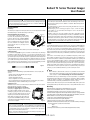
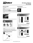
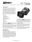
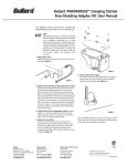
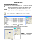
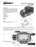
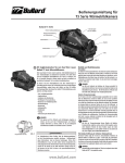
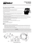
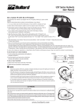
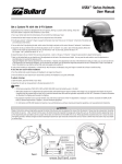
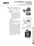
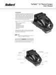
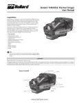
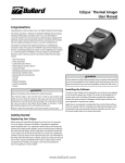
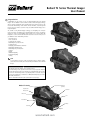
Bullard T3 Series Thermal Imager
User Manual
Congratulations
Congratulations on the purchase of your new advanced Bullard T3 Series Thermal
Imager. The new Bullard T3 Series combines advanced thermal imaging technology
with our expertise in high heat, impact resistant engineered polymers to bring you the
most durable thermal imager on the market. The T3’s innovative, compact design and
logical, easy-to-use interface presents a truly personalized thermal imaging tool to
today’s firefighters.
The benefits of using thermal imaging technology as a firefighting tool encompass
nearly every aspect of a firefighter’s job. Thermal imaging is not, however, a technology
designed to replace current firefighting tactics. Rather, it is a tool that allows the
firefighter to be more effective and make better decisions. Some of the many uses for
your Bullard T3 Series Thermal Imager include:
• Search and rescue
• Scene assessment
• Locating the seat of the fire
• Determining the spread of the fire
• Locating hot spots
• Identifying potential flashover situations
• Determining ventilation points
• Determining entry and exit points
• Overhaul
• Hazmat
• Wildland firefighting
• Incident investigating
• Training
Note
To ensure that we are able to reach you with any product or software updates,
please fill out the warranty card enclosed with your Bullard T3 Series Thermal
Imager.
Warning
Read all instructions and warnings before using this product.
Your thermal imager is like any other tool. It must be used properly and safely. All
users should be trained on the proper and safe use of thermal imaging prior to using
the T3 Series Thermal Imager. This is especially important for users who may use
the T3 Series Thermal Imager in hazardous or IDLH (immediately dangerous to life
and health) environments.
Failure to follow this information could result in death or serious injury.
Bullard T3 Series
Rear Boot
Electronic Thermal Throttle
(optional)
Polycarbonate
Display Cover
Lens Bezel
LCD Screen
Lens
Power Button
Battery
Side Strap
Figure 1
www.bullard.com
Use and Operation
Power
To turn on your Bullard T3 Series Thermal Imager, depress
and release the large, dark gray power button under the
LCD display (Figure 2). Upon pressing the power button
the thermal imager will display the Bullard logo and initiate
a calibration sequence. The thermal image will appear in
approximately 5 seconds. To turn off power, depress and Power Button
release the power button again.
Note
The Electronic Thermal Throttle takes approximately eight seconds to calibrate from the initial
startup of the thermal imager. During this short period, the ETT will not engage.
Figure 2
Note
You will periodically observe a momentary freeze in the image. This is normal and is a function of
the self calibration shutter. The shutter will activate every 30 seconds to three minutes, depending
on the environment.
Relative Heat Indicator (RHI)
The T3 Series is equipped with temperature measurement capability. The right side of the display will
show a bar graph or Relative Heat Indicator (RHI). The RHI will indicate the approximate temperature
of the object viewed within the “crosshairs” shown in the middle of the screen. The accuracy of the
indicators is dependent on numerous factors including the distance from the object being viewed and
its emissivity, which is the object’s ability to radiate heat. Units are calibrated with a preset emissivity
corresponding with normal construction materials. Objects with emissivities that vary greatly from this,
such as metals and shiny objects, will reduce the accuracy of the temperature indication. Additionally,
temperature measurement accuracy decreases as the distance from the object in the “crosshairs”
increases.
NOTE
The RHI provides a quick reference to compare objects of similar emissivities to serve as a guide
to pinpoint intense heat sources. Due to the inherent issues with accuracy, use this feature with
caution and verify indicated heat levels through traditional means whenever possible.
Super Red Hot Feature (optional)
The T3 Series features Super Red Hot high heat colorization. With the Super Red Hot feature, heat
levels are identified by various color hues. Starting at 250°Celsius , heated objects are tinted yellow and
gradually transition to orange and then solid red as heat levels rise. The Super Red Hot feature identifies
specific heat layers alerting firefighters to areas of intense heat. This feature provides an enhanced visual
awareness of the hottest objects in a scene.
NOTE
The T3MAX and T3MAX Plus cameras come standard with the Red Hot feature which colors in
red heated objects above 500° Celsius.
Electronic Thermal Throttle® (optional)
Figure 3
Your T3 Series Thermal Imager may be equipped with
Electronic Thermal Throttle (ETT), a highly useful and
unique feature available on Bullard firefighting Thermal
Imagers. The ETT is ideal for pinpointing hot spots during
overhaul, searching for overheated electrical equipment,
or clarifying objects in ambient temperature situations. To
activate the ETT option, locate the two black buttons on
top of the unit. Press the down button (the button closer to
the front of the imager) to activate the ETT (Figure 3).
The ETT will automatically sense the hottest area in the scene and color it blue. Continuing to press the
down button (or holding it down) will further engage ETT and will color more of the scene blue, eventually
coloring even the coolest objects blue.
Note
Using the Battery Charger
The battery should be charged in the battery charger using either the
AC or DC adapter provided (Figure 4).To charge a battery, insert it
into the charger so that the metal contacts on the battery are aligned
with the metal contacts in the charger. A red light will illuminate on the
charger to indicate that the battery is charging. When the light on the
charger turns to green, the battery is fully charged. You may leave the
battery in the charger indefinitely as the battery will not overcharge and
the charger will initiate a trickle charge to maintain the battery’s charge.
For maximum battery life and performance, you should remove the
battery from the charger and discharge it completely on a monthly basis.
Figure 4
Note
If you do not see the red LED illuminate when you place a battery into the charger, the battery is
not charging.
Loading/Unloading the Battery
Loading and unloading the battery on the Bullard T3 Series
is straightforward (Figure 5). To install a battery, slide
the battery into the groove on the bottom of the unit and
ensure that the battery is properly seated. To remove a
battery, depress both battery locking buttons simultaneously
and slide the battery out of the unit. Since it can only be
loaded one way, the battery is easily replaced in the dark.
Additionally, as with all batteries, your Bullard rechargeable
battery will experience a slow drain of its charge during
storage. The amount of drain varies widely based on storage
conditions. For best performance, charge each of your
batteries every two weeks.
Figure 5
Battery Locking Buttons
Warning
Do not allow the metal contacts on the label side of the battery to come in contact with a
conductive surface, such as a metal table or another battery. This can complete the battery
circuit and cause the battery to overheat or melt. Failure to observe this warning may result in
permanent battery damage, property damage and/or serious injury.
Note
Fully charged NiMH batteries will provide a run time of 2 1⁄2 hours. This run time will be less
in extreme heat or extreme cold conditions and/or if the transmitter is in use. To extend the
potential lifespan of your batteries, fully drain and recharge each battery monthly. To help extend
the life of the rechargeable batteries and prevent unexpected instances of uncharged batteries,
develop a clear formalized plan for maintaining, charging, and replacing your batteries.
B ullard provides an optional AA Alkaline battery case which can be used as an alternative to the standard
10 V NiMH rechargeable batteries. The AA alkaline battery case requires eight AA alkaline batteries.
Once the batteries are installed, the case loads into the unit in the same manner as the standard NiMH
battery. Due to the unique way that alkaline batteries disperse power to the unit, the LED indicators will
report battery levels that are not necessarily indicative of the battery’s actual remaining charge. Fully
charged AA Alkaline batteries will typically operate a Bullard T3 Series Thermal Imager for 2 hours.
Do not insert the AA Alkaline battery case into any Bullard T3 Series battery chargers, including the
Powerhouse.
As the throttle engages more of the scene, the blue will become lighter in hue to help differentiate
objects in the scene.
As you cycle through the scene, you’ll see the symbol “TT” and a corresponding number in the bottom left
hand corner of the display. The “TT” indicates “Thermal Throttle” mode. The number (0-100) is a point
of reference to indicate the level of Thermal Throttle engagement; by itself it has no specific meaning.
Most of the benefits of the ETT are accomplished with the first few presses of the button. To deactivate
the ETT or lessen the amount of blue in the scene, press (or hold) the right side of the cover, which is the
right button on the throttle. Alternatively, you can quickly deactivate the ETT, by pressing both buttons
simultaneously for one second or turning off the Eclipse and turning it back on.
www.bullard.com
Bullard T3 Series Thermal Imager
User Manual
Warning
Warning
The T3 Series thermal imagers are extremely sensitive to intense, radiant light. Never point
the T3 Series thermal imagers at the sun or any other source of extreme radiant light, as
this could severely damage the thermal imager.
Do not attempt to disassemble the Bullard T3 Series Thermal Imager. If the unit is
not functioning promptly return it to Bullard for evaluation. Disassembling the unit
voids all warranties.
Like all thermal imagers sold at the time of this printing, the Bullard T3 Series is not
certified as intrinsically safe.
Thermal Imaging is not a technology designed to replace current fire fighting
tactics. Rather, it is a tool that allows the firefighter to be more effective and to
make better decisions.
Firefighters cannot stop using basic firefighter safety tactics. All firefighters should
receive proper training on: how thermal imagers work; the uses and limitations of thermal
imagers; image interpretation; and the safety considerations for thermal imaging use. Do
not attempt to remove the lens gasket or the rear boot. These parts provide sealing and
removal will break the seal exposing the unit to potential water damage. Failure to follow
these instructions could result in death, serious injury and/or product damage.
Strap Assemblies
Side Straps
The side straps are designed to be field replaceable. Users can order replacements and install
them without having to return the thermal imager to the factory.
Removing/Installing the Side Straps
To remove either of the right or left side straps,
loosen the strap and pull it through the strap loop
located on either side of the LCD display (Figure
6). Remove the screw that holds the strap to the
imager. To install, fasten the strap to the unit using
the screw provided. Do not overtighten. Feed the
strap through the strap loop and adjust to the
desired length.
Strap Loop
Side Strap
Service
Figure 6
Adjusting the Side Straps
To adjust a side strap, loosen the hook and loop and set to the desired length.
Combination Strap
The combination strap (Figure 7) can be used either as a wrist strap to keep the imager
from falling if it should slip from your hand, or as a gear strap, hooked directly onto your
turnout gear or SCBA. As a wrist strap, the adjustable strap fits over the sleeve of your turnout
gear and can adjust to any size wrist. The strap can be easily attached to either D-ring located
on the thermal imager. As a gear strap, the strap can be attached to a D-ring on your turnout
gear or SCBA and to a D-ring on the thermal imager. A quick release buckle serves as a safety
release mechanism in case the thermal imager ever becomes lodged inhibiting movement.
Simply depress the buckle and the thermal imager releases from the strap.
Figure 7
Care Instructions
The Bullard T3 Series Thermal Imager requires little maintenance. For best results, after
each use:
• Clean the outside of the unit with mild soap or detergent.
• Wipe the lens with a soft cloth.
• Clean the display with a soft cloth.
• Check screw tightness on side straps and cover display
• Store your thermal imager in the optional truck mount or in the delivery case provided.
• All thermal imagers should be maintained using a proper program.
Cleaning the Lens
The Bullard T3 Series lens is recessed in an impact resistant bezel. The lens can be cleaned
with a soft cloth and soapy water as required.
Replacing the Video Display Cover Window
The display cover (Figure 8) has a scratch resistant
hard coating to minimize marring. However, if heavy
scratching or gouging does occur, the cover window can
be replaced. To do this, simply remove the four screws
along the top and bottom of the window. Remove the
plastic display cover window and replace with a new
one (part number T3WINDOW) making sure that the
countersink slots around the mounting holes are facing
Figure 8
outward. Do not overtighten.
CAUTION
Do not use solvents or paint thinners to clean your Bullard T3 Series Thermal Imager as
they could permanently mar the surface or degrade the protective properties of the casing.
Do not intentionally submerge the unit underwater or subject the unit to high pressure
water. Follow care instructions described above.
Failure to observe these instructions may result in product damage. Any damage caused
by improper care is not covered under warranty.
If your Bullard Thermal Imager is not performing properly, contact your local Bullard distributor
where you purchased the unit. Describe the problem to the Bullard dealer as completely as
possible. For your convenience, your local distributor will try to help you diagnose or correct
the problem over the phone. Before returning your Bullard Thermal Imager, you should verify
with your local distributor if the product should be returned to Bullard. Your local dealer and
Bullard Customer Service will provide you with written permission and a return authorization
number.
If the return is a non-warranty repair, your local distributor will provide you with a repair
invoice estimate. To authorize repair, you must provide a purchase order to your distributor for
the amount of the estimate. Once Bullard or a local distributor authorizes your repair, they will
issue you a return authorization number so that you can return the unit to the Bullard service
station. Bullard will repair the unit and ship it from our service station within 48 business hours.
If the cost of repairs exceeds the stated quote by more than 15% or by more than 100 Euro,
a Bullard representative will re-estimate your repair and your local distributor will contact you
for authorization to complete repairs. After repairs are completed and the goods have been
returned to you, the local distributor will invoice you for the actual repair amount.
NOTE
Do not attempt to disassemble the sealed case of your Bullard T3 Series Thermal
Imager. If the unit is not functioning properly, return it to Bullard (as described in the
Service section) for evaluation. Disassembling the unit voids all warranties.
Decontaminate and clean your Thermal Imager to remove any hazardous or contaminated
materials that may have settled on the product during use. Laws and/or shipping regulations
prohibit the shipment of hazardous or contaminated materials. Products suspected of
contamination will be professionally decontaminated at the customer’s expense.
Returned products will be inspected upon return to the Bullard facility. If the repair is under
warranty, Bullard will repair the unit and ship it from our factory within 48 business hours.
Warranty
Bullard warrants to the original purchaser that the Bullard T3 Series and all
features/accessories installed in the unit are free of defects in materials and
workmanship under intended use and service for a period of two (2) years from date of
manufacture. Bullard’s obligation under this warranty is limited to repairing or replacing, at Bullard’s
option, articles that are returned within the warranty period and that, after examination, are shown to
Bullard’s satisfaction to be defective, subject to the following limitations:
a) Article must be returned to Bullard with shipping charges prepaid.
b) Article must not be altered from its original configuration.
c) Article must not have been misused, abused, or damaged in transport.
d) Maintenance and field replaceable items, if defective, are covered under warranty for a ninety (90)
day period from the date of purchase. These items include:
• Straps
• Display covers
e) Warranty period for batteries is 1 year from manufacturing date indicated on battery
www.bullard.com
Bullard provides a limited lifetime warranty on the T3 Series outer shell. This warrants that the
outer shell is free of defects in materials and workmanship under intended use and service for the
original purchaser. Bullard’s obligation under this warranty is limited to repairing or replacing, at
Bullard’s option, articles that after examination are shown to Bullard’s satisfaction to be defective,
subject to the following limitations:
1. Article must not be altered from its original configuration.
2. Article must not have been misused, abused, or damaged in transport.
3. When the outer shell is obsolete and Bullard no longer stocks the part, the limited lifetime
warranty will be terminated.
In no event shall Bullard be responsible for damages, loss of use, or other indirect, incidental,
consequential or special costs, expenses or damages incurred by the purchaser, notwithstanding
that Bullard has been advised of the possibility of such damages.
Any implied warranties, including warranties of merchantability and fitness for
a particular purpose, are limited in duration to two (2) years from the date of
manufacture of this.
Some states do not allow the exclusion or limitation of incidental or consequential damages, or allow
limitations on how long an implied warranty lasts, so the above limitations or exclusions may not
apply to you. This warranty gives you specific legal rights, and you may have other rights which vary
from state to state.
For
accessories,
upgrades
replacement
visit
www.bullard.com,
Hiermit
erklärt E.D. Bullard Company,
daß diese and
Wärmebildkamera
TacSight SE35 parts,
den Vorschriften
der Direktive
1989/336/EC
entspricht.
or contact your local Bullard distributor.
Die Konformitätserklärung finden Sie hier.
Bullard
1898 Safety Way
Bullard GmbH
Lilienthalstrasse 12
Americas:
Europe:
Cynthiana, KY 41031-9303
53424 Remagen
Bullard
Bullard
GmbH
Toll free: 877-BULLARD
(285-5273)
Germany
Tel: 859-234-6616
1898 Safety Way
Lilienthalstrasse 12 phone: 0049-2642 999980
Fax: 859-234-8987
fax : 0049-2642 9999829
Cynthiana, KY 41031-9303 • USA
53424 Remagen • Germany
www.bullard.com
www.bullardextrem.com
Toll-free within USA: 877-BULLARD (285-5273)
Tel: +49-2642 999980
Tel: +1-859-234-6616
Fax: +49-2642 9999829
Fax: +1-859-234-8987
Bullard Asia Pacific Pte. Ltd.
Cisco Centre
Asia-Pacific:
20 Jalan Afifi, #08-03
Bullard
Pacific Pte. Ltd.
SingaporeAsia
409179
Tel: (65)
6745-0556
LHK
Building
Fax: (65) 6745-5176
701,
Sims Drive, #04-03
www.bullard.com
Singapore 387383
Tel: +65-6745-0556
Fax: +65-6745-5176
w w w.b u lla rd. c om
©2007 Bullard. All rights reserved.
ISO 9001
certified
Bullard is a registered trademark of Bullard.
ISO 9001
“It’s your life and you’re worth it”, Electronic
certified
Thermal Throttle, Super Red Hot, Relative Heat Indicator,
T3MAX and T3XT are trademarks of Bullard.
©20126050047353
Bullard. DE
All(0607)
rights reserved.
Electronic Thermal Throttle is a
registered trademark of Bullard.
6050047282C GMBH EN (0812)