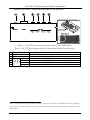
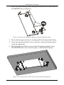
1
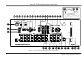
Kramer Electronics, Ltd.
USER MANUAL
Model:
VP-727T
Presentation Switcher Control Panel
Contents
Contents
1
1.1
2
2.1
3
4
5
6
7
7.1
7.2
7.3
8
8.1
8.2
Introduction
About the VP-727T Presentation Switcher Control Panel
Getting Started
Quick Start
Overview
Your VP-727T Presentation Switcher Control Panel
Installing in a Desktop
Installing on a Rack
Connecting the VP-727T
Connecting via RS-485
Connecting a PC (via RS-232)
Setting the Machine #
Operating the VP-727 using the VP-727T
Using the VP-727T WIPE DIRECTION Buttons
Making the Transition
1
1
1
1
2
3
7
9
10
11
12
12
13
13
14
8.2.1
8.2.2
Making a Transition Manually
Making a Transition Automatically
14
14
9
Technical Specifications
14
Figures
Figure 1: VP-727T Presentation Switcher Control Panel
Figure 2: VP-727T Presentation Switcher Control Panel (Side Panel)
Figure 3: Cut Out Dimensions
Figure 4: Inserting the VP-727T into the Prepared Cut Out Opening
Figure 5: Inserting the Mounting Brackets through the Bracket Slits
Figure 6: Securing the VP-727T into the Prepared Cut Out Opening
Figure 7: Connecting the VP-727T
Figure 8: Connecting the VP-727T RS-485 Ports
Figure 9: Connecting the PC
4
6
7
7
8
8
10
11
12
Tables
Table 1: VP-727T Presentation Switcher Control Panel Features
Table 2: VP-727T Presentation Switcher Control Panel (Side Panel) Features
Table 3: Defining the WIPE DIRECTIONS Buttons
Table 4: Technical Specifications of the VP-727T
5
6
13
14
i
Introduction
1
Introduction
Welcome to Kramer Electronics (since 1981): a world of unique, creative and
affordable solutions to the infinite range of problems that confront the video,
audio and presentation professional on a daily basis. In recent years, we have
redesigned and upgraded most of our line, making the best even better! Our
500-plus different models now appear in 8 Groups1, which are clearly defined
by function. Congratulations on purchasing your Kramer VP-727T Presentation
Switcher Control Panel, which is ideal for staging events, as well as:
Presentation applications that require a preview option
Projection systems in conference rooms, board rooms, auditoriums,
hotels, and churches
1.1 About the VP-727T Presentation Switcher Control Panel
The Kramer VP-727T Presentation Switcher Control Panel is used to control
the VP-727 Universal Presentation Matrix Switcher / Scaler2. The Kramer
VP-727T lets you remotely control switcher functions such as input selection,
transition effects (that include cut, fade, and wipes) and transition speed.
Note that the VP-727 needs firmware package Master FW 1.03 (Ver. 1.03)
(or higher) to work with the VP-727T.
The package includes: the VP-727T, gooseneck lamp, null-modem adapter,
power supply, rack ears kit3, table-top brackets, and this user manual4.
2
Getting Started
We recommend that you:
Unpack the equipment carefully and save the original box and packaging
materials for possible future shipment
Review the contents of this user manual
2.1 Quick Start
This Quick start chart summarizes the basic steps when connecting a VP-727T:
1 GROUP 1: Distribution Amplifiers; GROUP 2: Video and Audio Switchers, Matrix Switchers and Controllers; GROUP 3:
Video, Audio, VGA/XGA Processors; GROUP 4: Interfaces and Sync Processors; GROUP 5: Twisted Pair Interfaces;
GROUP 6: Accessories and Rack Adapters; GROUP 7: Scan Converters and Scalers; and GROUP 8: Cables and Connectors
2 A true multi-standard video to graphics scaler and seamless switcher with 8 universal inputs comprised of 5 BNC
connectors each of which can accommodate a composite video, s-Video (Y/C), component video (RGB/YUV), RGBS, or
RGBHV signal. It has dual scalers, one for the preview and the other for the program output. Dual scalers are required to do
"live" seamless transitions from one source to another
3 A pair of rack ears, two spacers and ten screws
4 Download up-to-date Kramer user manuals from the Internet at this URL: http://www.kramerelectronics.com
1
Overview
3
Overview
The VP-727T is a unique presentation switcher control panel dedicated
specifically to control the VP-727. It is ergonomically and aesthetically
designed in a rugged, professional 19" 4U rack-mountable metal enclosure
with the button layout in the style of the VP-727. In particular, the VP-727T:
2
KRAMER: SIMPLE CREATIVE TECHNOLOGY
Your VP-727T Presentation Switcher Control Panel
Enables special effect transitions between two sources via a robust T-bar
(used for manual control of transition speeds). Alternatively, the effect can be
implemented via a TAKE button, with a potentiometer to set the transition speed
Features single button access to all inputs1—both for the Preview and for the
Program output—and the buttons have removable transparent caps to allow labeling
Features dedicated single button actions for special effect selection,
immediate freezing and blanking, PIP display, and the choice of wipe direction
Has the user menu—conveniently located on the VP-727T panel—for
complete control of the VP-727 via its Preview OSD
Consol can be simultaneously connected to up to four VP-727 machines.
Control communication is via the RS-485 port, thus allowing the panel to be
located more than 1km from each VP-727
Has an RS-232 port for field upgrading of its firmware
With its angled faceplate, may be used freestanding on a table, or
mounted in a desktop or in a 19” rack (when your switcher is rack-mounted
near to the source devices, you can conveniently place the VP-727T on a table
or desk away from the equipment rack)
Has a gooseneck lamp (included) that can be plugged into the consol for
use in low lighting environments
Is powered by a 12V DC source
To achieve the best performance:
Connect only good quality connection cables
Avoid interference from neighboring electrical appliances, make sure not
to block the ventilation holes and position your VP-727T away from moisture,
excessive sunlight and dust. Be sure to position it straight in the correct
horizontal position on the table, desk or rack
Caution – No operator-serviceable parts inside unit.
Warning – Use only the Kramer Electronics input power
wall adapter that is provided with this unit2.
Warning – Disconnect power and unplug unit from wall
before installing or removing device or servicing unit.
4
Your VP-727T Presentation Switcher Control Panel
Figure 1 and Table 1 define the front panel of the VP-727T:
1 Has two sets of input buttons: one that routes the input to the "PROGRAM" output and the other that routes to the
"PREVIEW" output
2 For example: model number AD2512C, part number 2535-000251
3
Your VP-727T Presentation Switcher Control Panel
Figure 1: VP-727T Presentation Switcher Control Panel
4
KRAMER: SIMPLE CREATIVE TECHNOLOGY
Your VP-727T Presentation Switcher Control Panel
Table 1: VP-727T Presentation Switcher Control Panel Features
5
6
7
Feature
LAMP Button
MENU Button
ENTER Button
CONTROLLER ON
Button
Moves up one step (in the same level) in the OSD menu
Toggles within each level 2 command / increases the range by one step
14
15
16
17
TRANSITION Buttons
13
3,5
8
9 OSD Button
10 FADE 2 Button
11 CUT 2 Button
12
Function
Toggles the gooseneck lamp ON/OFF
Displays the OSD Menu screen (or moves to the previous level in the OSD menu)
Moves to the next level in the OSD menu
Toggles the VP-727T Presentation Switcher Control Panel ON/OFF
Toggles within each level 2 command / decreases the range by one step
OSD
NAVIGATION
Buttons
#
1
2
3
4
Moves down one step (in the same level) in the OSD menu
Activates/deactivates access to the OSD Menu1
Selects a dissolved transition from the PREVIEW to the PROGRAM output
Selects an instantaneous transition from the PREVIEW to the PROGRAM output
Selects a WIPE transition effect
Selects a DIAGONAL transition effect
Selects a CIRCLE transition effect
Selects a SQUARE transition effect
Selects a CORNER transition effect
Selects a CHESSBOARD transition effect
18 WIPE DIRECTION
Buttons
Choose the direction of the effect4: inwards, outwards, “left to right”, “right to
left”, “up” or “down” (see section 8.2)
19 SPEED Knob
Adjusts the TAKE button transition speed
20 TAKE Button5
Pressing TAKE causes the transition to occur automatically
21 PREVIEW LED
Lights when the T-bar Controller is directed upwards
Lights when the T-bar Controller is directed downwards
23 T-bar Control Lever6
Slide to manually implement the effect using the T-bar handle
24
25
PIP
BLANK
Toggles the picture-in-picture function on and off
Toggles between a blank screen and the selected input
FREEZE
Freezes the output video image (toggle)
INPUTS
Selects one of the sources: R/PR, G/Y/CV, B/PB/C, HS/CS, VS (from 1 to 8)
27
28
29
30
31
PREVIEW
Buttons
26
PROGRAM
Buttons
22 PREVIEW LED
PIP
Toggles the picture-in-picture function on and off
BLANK
Toggles between a blank screen and the selected input
FREEZE
Freezes the output video image (toggle)
INPUTS
Selects one of the sources: R/PR, G/Y/CV, B/PB/C, HS/CS, VS (from 1 to 8)
32 MACHINE # Button
Pressing selects which MACHINE # is controlled
33 7-segment LED Display
Shows the MACHINE #
34 Lamp Connector
Connects to the gooseneck lamp
1 The LCD is not affected by the OSD setting
2 Only for setting up the unit for the effect. The effect will only occur when the Take button is pressed, or the T-bar is moved
3 Select a specific effect for the transition from the PREVIEW output to the PROGRAM output
4 From where the effect starts
5 The effect is only seen in PROGRAM Mode. The PREVIEW screen will blank during the transition
6 An alternative to using the TAKE button
5
Your VP-727T Presentation Switcher Control Panel
Figure 2 and Table 2 define the side panel of the VP-727T:
Figure 2: VP-727T Presentation Switcher Control Panel (Side Panel)
Table 2: VP-727T Presentation Switcher Control Panel (Side Panel) Features
TO VP-727
3-PIN
Terminal
Block
# Feature
1 12V DC
2 RS-232 DB 9 Connector
3
MACH. # 4
4
MACH. # 3
5
MACH. # 2
6
MACH. # 1
Function
+12V DC connector for powering the unit
Connects to the PC for upgrading the firmware
Connects to the RS-485 port1 on the VP-727 which is recognized as machine # 4
Connects to the RS-485 port1 on the VP-727 which is recognized as machine # 3
Connects to the RS-485 port1 on the VP-727 which is recognized as machine # 2
Connects to the RS-485 port1 on the VP-727 which is recognized as machine # 1
1 Pin G is for the Ground connection, which is sometimes connected to the shield of the RS-485 cable. In most applications,
the ground is not connected; pins B (-) and A (+) are for RS-485. The RS-485 PINOUT: GBA may not be printed on some
VP-727T units
6
KRAMER: SIMPLE CREATIVE TECHNOLOGY
Installing in a Desktop
5
Installing in a Desktop
This section describes how to install the VP-727T in a desktop1.
To install the VP-727T in a desktop:
1. Cut an opening in the desktop—making the cut out on a wooden surface
using a sabre saw or a keyhole saw—at the location where you want to
insert the VP-727T. Figure 3 illustrates the cut out template (not to scale)
defining the surface that you have to cut out to install your VP-727T.
Figure 3: Cut Out Dimensions
2. Carefully insert the VP-727T unit into the prepared cut out opening, as
illustrated in Figure 4.
Figure 4: Inserting the VP-727T into the Prepared Cut Out Opening
1 Alternatively, you can use it freestanding on a table, or mounted in a 19” rack (see section 6)
7
Installing in a Desktop
3. Insert the two mounting brackets through the bracket slits on both sides of
the VP-727T unit (see Figure 5).
Figure 5: Inserting the Mounting Brackets through the Bracket Slits
4. Be sure that the upper outer rim is situated parallel to the edge of the desktop.
5. Screw the mounting butterfly screws until they reach the desktop surface
(from the underneath).
6. Tighten the locking butterfly screws to lock the mounting butterfly screws.
The VP-727T unit is now secured in place, as illustrated in Figure 6.
Figure 6: Securing the VP-727T into the Prepared Cut Out Opening
8
KRAMER: SIMPLE CREATIVE TECHNOLOGY
Installing on a Rack
6
Installing on a Rack
This section describes what to do before installing on a rack and how to rack
mount.
Before Installing on a Rack
Before installing on a rack, be sure that the environment is
within the recommended range:
Operating temperature range +5 to +45 Deg. Centigrade
Operating humidity range
5 to 65% RHL, non-condensing
Storage temperature range
-20 to +70 Deg. Centigrade
Storage humidity range
5 to 95% RHL, non-condensing
How to Rack Mount
To rack-mount the machine:
1
Attach both ear brackets to the
machine. To do so, fasten the 5
screws on each side of the
machine through the ear bracket
via the spacer, securing both ear
brackets to the machine.
CAUTION!!
When installing on a 19" rack, avoid hazards by taking care
that:
1
It is located within the recommended environmental
conditions, as the operating ambient temperature of a
closed or multi unit rack assembly may exceed the room
ambient temperature.
2
Once rack mounted, enough air will still flow around the
machine.
3
The machine is placed straight in the correct horizontal
position.
4
You do not overload the circuit(s). When connecting the
machine to the supply circuit, overloading the circuits
might have a detrimental effect on overcurrent protection
and supply wiring. Refer to the appropriate nameplate
ratings for information. For example, for fuse replacement,
see the value printed on the product label.
5
The machine is earthed (grounded) in a reliable way and
is connected only to an electricity socket with grounding.
Pay particular attention to supply connections other than
direct connections to the branch circuit (for example, the
use of power strips), and that you use only the power cord
that is supplied with the machine.
2
Place the ears of the machine
against the rack rails, and insert
the proper screws (not provided)
through each of the four holes in
the rack ears.
Note that:
In some models, the front panel
may feature built-in rack ears
Detachable rack ears can be
removed for desktop use
Always mount the machine in the
rack before you attach any cables or
connect the machine to the power
If you are using a Kramer rack
adapter kit (for a machine that is not
19"), see the Rack Adapters user
manual for installation instructions
(you can download it at:
http://www.kramerelectronics.com)
9
Connecting the VP-727T
7
Connecting the VP-727T
To connect the VP-727T to up to four VP-727 machines, as the example in
Figure 7 illustrates1, do the following2:
1. Connect the “TO VP-727” RS-485 3-PIN terminal block ports of the
VP-727T, as follows (see section 7.1):
MACH. # 1 to the RS-485 port of the VP-727 which will be recognized as
machine # 1
MACH. # 2 to the RS-485 port of the VP-727 which will be recognized as
machine # 2
MACH. # 3 to the RS-485 port of the VP-727 which will be recognized as
machine # 3
MACH. # 4 to the RS-485 port of the VP-727 which will be recognized as
machine # 4
2. Connect the 12V DC power adapter to the power socket and connect the
adapter to the mains electricity (not illustrated in Figure 7).
Figure 7: Connecting the VP-727T
1 The RS-232 port is for firmware upgrade only, see section 7.2
2 Switch OFF the power on each device before connecting it to your VP-727T. After connecting your VP-727T, switch on its
power and then switch on the power on each device
10
KRAMER: SIMPLE CREATIVE TECHNOLOGY
Connecting the VP-727T
7.1 Connecting via RS-485
When connecting the “TO VP-727” RS 485 3 PIN terminal block ports of the
VP-727T, to the respective VP-727 machine, connect the:
“A” (+) PIN of the VP-727T to the “A” (+) PIN of the VP-727
“B” (+) PIN of the VP-727T to the “B” (+) PIN of the VP-727
If shielded twisted pair cable is used, the shield may be connected to the
“G” (Ground) PIN on one of the units
Figure 8: Connecting the VP-727T RS-485 Ports
11
Connecting the VP-727T
7.2 Connecting a PC (via RS-232)
You can connect a PC (or other controller) to the VP-727T via the RS-232
port for upgrading the firmware.
To connect a PC to a VP-727T unit, using the Null-modem adapter provided
with the machine (recommended):
Connect the RS-232 DB9 rear panel port on the VP-727T unit to the
Null-modem adapter and connect the Null-modem adapter with a 9 wire flat
cable to the RS-232 DB9 port on your PC
To connect a PC to a VP-727T unit, without using a Null-modem adapter:
Connect the RS-232 DB9 port on your PC to the RS-232 DB9 rear panel
port on the VP-727T unit, forming a cross-connection1, as Figure 9 illustrates
DB9 (FromPC)
DB9 (To Presentation
Switcher / Scaler)
Figure 9: Connecting the PC
7.3 Setting the Machine #
The VP-727T automatically recognizes the MACHINE # of each VP-727 unit.
For example, the VP-727 unit that is connected to the “ TO VP-727” RS 485
port MACH. # 3 is recognized as the third VP-727 unit: MACHINE # 3.
To access this particular VP-727 unit from the VP-727T, press the MACHINE #
button2 until the number 3 is selected in the 7-segment LED display3.
1 Also known as a Null-modem connection
2 Item 32 in Figure 1 and Table 1
3 Item 33 in Figure 1 and Table 1
12
KRAMER: SIMPLE CREATIVE TECHNOLOGY
Operating the VP-727 using the VP-727T
8
Operating the VP-727 using the VP-727T
For details of how to operate the VP-727 via the OSD Menu, LCD Display,
ETHERNET, and/or RS-232, including using the TAKE button, refer to the
VP-727 user manual1. For details of how to:
Use the WIPE DIRECTION buttons, see section 8.1
Adjust the transition speed, see section 8.2
8.1 Using the VP-727T WIPE DIRECTION Buttons
To set the wipe direction, use the WIPE DIRECTION buttons2 (see Table 3):
Table 3: Defining the WIPE DIRECTIONS Buttons
EFFECTS
WIPE DIRECTIONS
Choice of four
directions (only
one button is
selected)
Wipe
Choice of four
directions (two
buttons are
selected
simultaneously)
Diagonal
Circle
In
Out
Square
In
Out
Corner
Chessboard In
Choice of four
directions (two
buttons are
selected
simultaneously)
Out
1 Download up-to-date Kramer user manuals from the Internet at this URL: http://www.kramerelectronics.com
2 Item 18 in Figure 1 and Table 1
13
Technical Specifications
8.2 Making the Transition
You can make the transition in two ways:
Manually, for each separate transition using the T-bar control lever1
Automatically, via the TAKE button, which implements the transition at
the pace set by the SPEED2 knob
8.2.1
Making a Transition Manually
To make the transition, manually:
Slide the T-bar handle upwards3 or downwards4
8.2.2
Making a Transition Automatically
To make the transition, automatically:
Rotate the SPEED knob2 to the right (increasing the transition speed) or
to the left (decreasing the transition speed). When the knob is turned to the
extreme counter-clockwise position (off), the switch will be engaged to turn
the knob off. In this position, the speed setting is controlled via the setting in
the VP-727 OSD menu
Pressing the TAKE button5 causes the transition to occur automatically
9
Technical Specifications
Table 4 includes the technical specifications:
6
Table 4: Technical Specifications of the VP-727T
PORTS:
CONTROLS:
POWER SOURCE:
DIMENSIONS:
WEIGHT:
ACCESSORIES:
4 sets of RS-485 3-PIN Terminal Block Ports
Front panel buttons, RS-232, and RS-485
12 VDC, 240mA
19” (W), 3.4” (D), 4RU (H) rack mountable7
1.58kg. (3.5 lbs.) approx.
Gooseneck lamp, null-modem adapter, power supply, rack ears
kit8, and table-top brackets
1 Item 23 in Figure 1 and Table 1
2 Item 19 in Figure 1 and Table 1
3 The PREVIEW LED lights (item 21 in Figure 1 and Table 1)
4 The PREVIEW LED lights (item 22 in Figure 1 and Table 1)
5 Item 20 in Figure 1 and Table 1
6 Specifications are subject to change without notice
7 48.2cm (W), 8.6cm (D), 17.7cm (H)
8 A pair of rack ears, two spacers and ten screws
14
KRAMER: SIMPLE CREATIVE TECHNOLOGY
LIMITED WARRANTY
Kramer Electronics (hereafter Kramer) warrants this product free from defects in material and workmanship under the
following terms.
HOW LONG IS THE WARRANTY
Labor and parts are warranted for seven years from the date of the first customer purchase.
WHO IS PROTECTED?
Only the first purchase customer may enforce this warranty.
WHAT IS COVERED AND WHAT IS NOT COVERED
Except as below, this warranty covers all defects in material or workmanship in this product. The following are not covered
by the warranty:
1.
2.
3.
Any product which is not distributed by Kramer, or which is not purchased from an authorized Kramer dealer. If you are
uncertain as to whether a dealer is authorized, please contact Kramer at one of the agents listed in the web site
www.kramerelectronics.com.
Any product, on which the serial number has been defaced, modified or removed.
Damage, deterioration or malfunction resulting from:
i)
Accident, misuse, abuse, neglect, fire, water, lightning or other acts of nature
ii)
Product modification, or failure to follow instructions supplied with the product
iii)
Repair or attempted repair by anyone not authorized by Kramer
iv)
Any shipment of the product (claims must be presented to the carrier)
v)
Removal or installation of the product
vi)
Any other cause, which does not relate to a product defect
vii)
Cartons, equipment enclosures, cables or accessories used in conjunction with the product
WHAT WE WILL PAY FOR AND WHAT WE WILL NOT PAY FOR
We will pay labor and material expenses for covered items. We will not pay for the following:
1.
2.
3.
Removal or installations charges.
Costs of initial technical adjustments (set-up), including adjustment of user controls or programming. These costs are the
responsibility of the Kramer dealer from whom the product was purchased.
Shipping charges.
HOW YOU CAN GET WARRANTY SERVICE
1.
2.
3.
To obtain service on you product, you must take or ship it prepaid to any authorized Kramer service center.
Whenever warranty service is required, the original dated invoice (or a copy) must be presented as proof of warranty coverage,
and should be included in any shipment of the product. Please also include in any mailing a contact name, company, address, and
a description of the problem(s).
For the name of the nearest Kramer authorized service center, consult your authorized dealer.
LIMITATION OF IMPLIED WARRANTIES
All implied warranties, including warranties of merchantability and fitness for a particular purpose, are limited in duration to
the length of this warranty.
EXCLUSION OF DAMAGES
The liability of Kramer for any effective products is limited to the repair or replacement of the product at our option. Kramer
shall not be liable for:
1.
2.
Damage to other property caused by defects in this product, damages based upon inconvenience, loss of use of the product, loss
of time, commercial loss; or:
Any other damages, whether incidental, consequential or otherwise. Some countries may not allow limitations on how long an
implied warranty lasts and/or do not allow the exclusion or limitation of incidental or consequential damages, so the above
limitations and exclusions may not apply to you.
This warranty gives you specific legal rights, and you may also have other rights, which vary from place to place.
NOTE: All products returned to Kramer for service must have prior approval. This may be obtained from your dealer.
This equipment has been tested to determine compliance with the requirements of:
EN-50081:
"Electromagnetic compatibility (EMC);
generic emission standard.
Part 1: Residential, commercial and light industry"
EN-50082:
"Electromagnetic compatibility (EMC) generic immunity standard.
Part 1: Residential, commercial and light industry environment".
CFR-47:
FCC Rules and Regulations:
Part 15: “ Radio frequency devices
Subpart B – Unintentional radiators”
CAUTION!
Servicing the machines can only be done by an authorized Kramer technician. Any user who makes changes or modifications to
the unit without the expressed approval of the manufacturer will void user authority to operate the equipment.
Use the supplied DC power supply to feed power to the machine.
Please use recommended interconnection cables to connect the machine to other components.
15
For the latest information on our products and a list of Kramer
distributors, visit our Web site: www.kramerelectronics.com,
where updates to this user manual may be found.
We welcome your questions, comments and feedback.
Safety Warning:
Disconnect the unit from the power supply before
opening/servicing.
Caution
Kramer Electronics, Ltd.
Web site: www.kramerelectronics.com
E-mail: [email protected]
P/N: 2900-000195 REV 1A