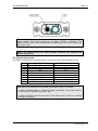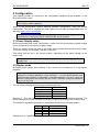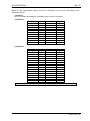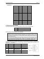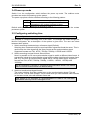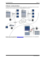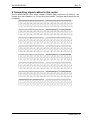
1
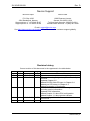
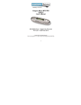
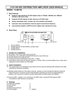
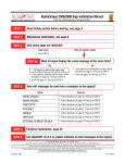
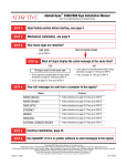
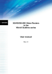
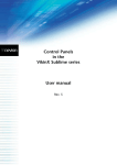
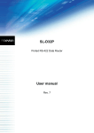
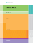
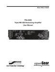
SL-3GHD128128 VikinX Sublime 128x128 3G/HD/SD-SDI Router User manual Rev. D Nevion Nordre Kullerød 1 3241 Sandefjord Norway Tel: +47 33 48 99 99 nevion.com SL-3GHD128128 Rev. D Nevion Support Nevion Europe Nevion USA P.O. Box 1020 3204 Sandefjord, Norway Support phone 1: +47 33 48 99 97 Support phone 2: +47 90 60 99 99 1600 Emerson Avenue Oxnard, CA 93033, USA Toll free North America: (866) 515-0811 Outside North America: +1 (805) 247-8560 E-mail: [email protected] See http://www.nevion.com/support/ for service hours for customer support globally. Revision history Current revision of this document is the uppermost in the table below. Rev. Repl. Date Sign Change description D 3 3 2 2013-07-18 2011-10-13 JGS NBS 2 1 2010-05-21 NBS 1 0 2010-02-26 NBS 0 - 2010-02-03 NBS Update to new template, no change in document Corrected housing and gender spec on D-sub 9-pin contacts. Updated Chapter 2.5. Added SD-SDI Cable EQ spec in Chapter 2.4. Added one LED status in Chapter 4.2. Added Declaration of Conformity, Added information about Nevion Configurator, including version information. Updated PSU information. Added Chapter 3.1 about PSU configuration. Added Chapter 1.1 about product variants. Corrected hyperlink to Multicon and other minor corrections. First release. nevion.com | 2 SL-3GHD128128 Rev. D Contents Revision history ........................................................................................................ 2 1 Product overview ................................................................................................... 4 1.1 Product variants ............................................................................................................ 5 2 Specifications ........................................................................................................ 7 2.1 Mechanics ..................................................................................................................... 7 2.2 Power supply ................................................................................................................ 7 2.3 Control .......................................................................................................................... 7 2.4 Video specifications ...................................................................................................... 7 2.5 Rear view ...................................................................................................................... 9 2.5.1 Power Supply pinout .................................................................................................. 9 2.5.2 Serial port pinout .......................................................................................................10 3 Configuration ....................................................................................................... 11 3.1 Power Supply setup .....................................................................................................11 3.2 Router mode ................................................................................................................11 3.3 External power alarm ...................................................................................................13 3.4 Power-up mode ............................................................................................................14 3.5 Configuring switching time ...........................................................................................14 4 LED status indication ........................................................................................... 15 4.1 Start-up ........................................................................................................................15 4.2 Alarm states .................................................................................................................15 4.3 Ethernet states .............................................................................................................15 5 Router communication......................................................................................... 16 6 Connecting signal cables to the router ................................................................ 17 General environmental requirements for Nevion equipment .................................. 18 Product Warranty.................................................................................................... 19 Important notes regarding Software in the VikinX Sublime router family range ...... 20 Appendix A Materials declaration and recycling information .................................. 21 A.1 Materials declaration ....................................................................................................21 A.2 Recycling information...................................................................................................21 nevion.com | 3 SL-3GHD128128 Rev. D 1 Product overview Nevion proudly presents Sublime SL-3GHD128128. With this router, Nevion continues a stable and proven product line including the most complete signal format and size offering available. With the ultra slim, multi format and flexible product range, Sublime fulfils the most demanding requirements from the professional broadcast market. This User Manual presents the features, installation and operation procedures of the SL-3GHD128128 router of the Sublime range. The key features of SL-3GHD128128 are: Multi rate support; 3G/HD/SD-SDI Supports DVB-ASI Supported bitrates: 143Mbps - 3Gbps Reclocking on standard 3G/HD/SD-SDI signals. Reclockers may be turned off, for support of E4/STM-1e Ethernet and RS-232 control interfaces Software based Configurator for easy system set-up Ultra Slim frame depth Low Power consumption (<150W); high reliability design Redundant power supply system with front indicators Interoperability with existing VikinX routers Possible to split the router into independent partitions on separate levels Multicon is embedded in the router All control features that come with Multicon (VX-SLC) are available as default Future proof and flexible product range VikinX Sublime provides many of the powerful control features that drove the VikinX Modular range to success. VikinX Sublime is ideal for general purpose facilities, on-air routing, mobile outside broadcast applications and sophisticated A/V applications. VikinX Sublime SL-3GHD128128 provides most important 3rd party control interfaces allowing the control of our routers through 3rd party management software. On top of that the embedded Multicon system controller allows control of the most common 3rd party routers. This enables you to utilize existing routers and management systems from other nevion.com | 4 SL-3GHD128128 Rev. D manufacturers and still draw the advantages of implementing VikinX Sublime in your routing application. 1.1 Product variants There are a number of variants for this product. They all share the same hardware, and are distinguished by FW keys. Item SL-3GHD128128 SL-3GHD96128 SL-3GHD96128 SL-3GHD64128 SL-3GHD12864 SL-3GHD32128 SL-3GHD12832 SL-3GHD9696 SL-3GHD6496 SL-3GHD9664 SL-3GHD3296 SL-3GHD9632 Description 128x128 HD-SDI Router (Multi rate, 270Mbps-2.970Gbps). Supports 3G-SDI, HD-SDI, SD-SDI, DVB-ASI, Ethernet/RS-232 control, router partitioning on separate levels, 19" 8RU depth 5cm. Multicon VX-SLC embedded controller. 96x128 HD-SDI Router (Multi rate, 270Mbps-2.970Gbps). Supports 3G-SDI, HD-SDI, SD-SDI, DVB-ASI. Upgradeable to 128x128. Ethernet/RS-232 control, router partitioning on separate levels, 19" 8RU depth 5cm. Multicon VX-SLC embedded controller. 128x96 HD-SDI Router (Multi rate, 270Mbps-2.970Gbps). Supports 3G-SDI, HD-SDI, SD-SDI, DVB-ASI. Upgradeable to 128x128. Ethernet/RS-232 control, router partitioning on separate levels, 19" 8RU depth 5cm. Multicon VX-SLC embedded controller. 64x128 HD-SDI Router (Multi rate, 270Mbps-2.970Gbps). Supports 3G-SDI, HD-SDI, SD-SDI, DVB-ASI. Upgradeable to 128x128. Ethernet/RS-232 control, router partitioning on separate levels, 19" 8RU depth 5cm. Multicon VX-SLC embedded controller. 128x64 HD-SDI Router (Multi rate, 270Mbps-2.970Gbps). Supports 3G-SDI, HD-SDI, SD-SDI, DVB-ASI. Upgradeable to 128x128. Ethernet/RS-232 control, router partitioning on separate levels, 19" 8RU depth 5cm. Multicon VX-SLC embedded controller. 32x128 HD-SDI Router (Multi rate, 270Mbps-2.970Gbps). Supports 3G-SDI, HD-SDI, SD-SDI, DVB-ASI. Upgradeable to 128x128. Ethernet/RS-232 control, router partitioning on separate levels, 19" 8RU depth 5cm. Multicon VX-SLC embedded controller. 128x32 HD-SDI Router (Multi rate, 270Mbps-2.970Gbps). Supports 3G-SDI, HD-SDI, SD-SDI, DVB-ASI. Upgradeable to 128x128. Ethernet/RS-232 control, router partitioning on separate levels, 19" 8RU depth 5cm. Multicon VX-SLC embedded controller. 96x96 HD-SDI Router (Multi rate, 270Mbps-2.970Gbps). Supports 3G-SDI, HD-SDI, SD-SDI, DVB-ASI. Upgradeable to 128x128. Ethernet/RS-232 control, router partitioning on separate levels, 19" 8RU depth 5cm. Multicon VX-SLC embedded controller. 64x96 HD-SDI Router (Multi rate, 270Mbps-2.970Gbps). Supports 3G-SDI, HD-SDI, SD-SDI, DVB-ASI. Upgradeable to 128x128. Ethernet/RS-232 control, router partitioning on separate levels, 19" 8RU depth 5cm. Multicon VX-SLC embedded controller. 96x64 HD-SDI Router (Multi rate, 270Mbps-2.970Gbps). Supports 3G-SDI, HD-SDI, SD-SDI, DVB-ASI. Upgradeable to 128x128. Ethernet/RS-232 control, router partitioning on separate levels, 19" 8RU depth 5cm. Multicon VX-SLC embedded controller. 32x96 HD-SDI Router (Multi rate, 270Mbps-2.970Gbps). Supports 3G-SDI, HD-SDI, SD-SDI, DVB-ASI. Upgradeable to 128x128. Ethernet/RS-232 control, router partitioning on separate levels, 19" 8RU depth 5cm. Multicon VX-SLC embedded controller. 96x32 HD-SDI Router (Multi rate, 270Mbps-2.970Gbps). Supports 3G-SDI, HD-SDI, SD-SDI, DVB-ASI. Upgradeable to 128x128. nevion.com | 5 SL-3GHD128128 Rev. D Item Description Ethernet/RS-232 control, router partitioning on separate levels, 19" 8RU depth 5cm. Multicon VX-SLC embedded controller. SL-3GHD64+ 64x64 HD-SDI Router (Multi rate, 270Mbps-2.970Gbps). Supports 3G-SDI, HD-SDI, SD-SDI, DVB-ASI. Upgradeable to 128x128. Ethernet/RS-232 control, router partitioning on separate levels, 19" 8RU depth 5cm. Multicon VX-SLC embedded controller. SL-3GHD3264+ 32x64 HD-SDI Router (Multi rate, 270Mbps-2.970Gbps). Supports 3G-SDI, HD-SDI, SD-SDI, DVB-ASI. Upgradeable to 128x128. Ethernet/RS-232 control, router partitioning on separate levels, 19" 8RU depth 5cm. Multicon VX-SLC embedded controller. SL-3GHD6432+ 64x32 HD-SDI Router (Multi rate, 270Mbps-2.970Gbps). Supports 3G-SDI, HD-SDI, SD-SDI, DVB-ASI. Upgradeable to 128x128. Ethernet/RS-232 control, router partitioning on separate levels, 19" 8RU depth 5cm. Multicon VX-SLC embedded controller. SL-3GHD32+ 32x32 HD-SDI Router (Multi rate, 270Mbps-2.970Gbps). Supports 3G-SDI, HD-SDI, SD-SDI, DVB-ASI. Upgradeable to 128x128. Ethernet/RS-232 control, router partitioning on separate levels, 19" 8RU depth 5cm. Multicon VX-SLC embedded controller. SL-UPG-32IN Upgrade to add 32x Inputs to your partly configured SL3GHD128128 router. SL-UPG-32OUT Upgrade to add 32x Outputs to your partly configured SL3GHD128128 router. SL-UPG-32IN+OUT Upgrade to add 32x Inputs and Outputs to your partly configured SL3GHD128128 router. Power Supply Unit SL-PWR-300 300W AC Power Supply Unit for Sublime 128 range. 48VDC output. nevion.com | 6 SL-3GHD128128 Rev. D 2 Specifications 2.1 Mechanics Dimensions: Router weight: Max. Power consumption: Safety/Emission standards: HxWxD = 355x483x50mm, (19”, 8RU). 7.75 kg, including 1x PSU module (1.15 kg). +48V, 2.8A; 135W. Compliant with CE EN55103-1 and 2. 2.2 Power supply SL-PWR-300: AC Supply voltage range: AC Mains connector: DC output: DC connector: Alarms: Alarms connector: Safety standards: 300 W Power supply Unit. 90-130VAC / 180-254VAC, switchable, 50-60Hz, 300W. IEC 320. +48V, max. 6.25A. Maximum 300 W. DSUB 2V2P. Power failure alarm on LED in front and GPI output from MULTICON. RJ45. Compliant with CE EN60950, UL-1950/CSA22.2. 2.3 Control Standard Features: Serial port: Connector(s): Ethernet port: Connector: Reclocker option: Input Equalizer option: Synchronization handled by Multicon: RS-232 for protocol conversion, to VikinX compact control protocol, or to third party protocols. DE9, D-sub 9-pin female. 10/100BaseT Ethernet bus for external router control. RJ45. Bypass of reclocking (from system controller). Bypass of input equalization (from system controller). Analog Black&Burst, looped. Both PAL and NTSC supported. Tri-Level, Looped. For HD signal formats only. Distribution of synchronization signals between several routers. BNC. Connector(s): Other features: SNMP agent, included with Multicon. 2.4 Video specifications Supported formats: Telecom: Broadcast: Supported standards: SD-SDI, 270Mbps: HD-SDI, 1.485Gbps: 3G-SDI, 2.97Gbps: DVB-ASI: Electrical signal inputs: Connectors: Impedance: STM-1e and E4. 143Mbps – 2.97Gbps. DVB-ASI, SMPTE 259M, SMPTE 292M, SMPTE 310M, SMPTE 424M. 2K, 2048x1556/23.98 and 24. SMPTE 259M. SMPTE 292-2008. SMPTE 424M. EN50083-9. BNC, IEC 61169-8. 75 Ohm. nevion.com | 7 SL-3GHD128128 Return loss: Cable equalization: Rev. D - Electrical signal outputs: Connector: Impedance: Return loss: Signal level: Rise/fall time: Amplitude overshoot: Signal polarity: Signal transition: Timing jitter: Alignment jitter: Reference inputs: Number of inputs: Connector: Return loss: Signal format: Signal level: Field selectivity: Timing range: > 15dB (5 MHz – 1.485 GHz); > 10dB (1.5 – 3 GHz). Automatic up to 70m @ 2.97Gbps, typical Belden 1694A; Automatic up to 100m @ 1.485Gbps, typical Belden 1694A; Automatic up to 300m @ 270Mbps, typical Belden 8281. BNC, IEC 61169-8. 75 Ohm. > 15dB (5 MHz – 1.485 GHz); > 10dB (1.5 – 3 GHz). 800mVp-p ±10%. 20% - 80% SD limit: 0.4ns – 1.5ns, < 0.5ns rise/fall variation; HD limit: < 270ps, < 100ps rise/fall variation; 3G limit: < 135ps, < 50ps rise/fall variation. < 10%. Non-inverting electrical with respect to inputs. - SD: < 0.2 UI; 3G / HD: < 1 UI. SD: < 0.2 UI; 3G / HD: < 0.2 UI. 1. 75 ohm BNC female, loop-thru. >40dB (100 kHz – 5 MHz); >35dB (5-10 MHz). NTSC or PAL Black&Burst or HD Tri-Level according to SMPTE 274M, SMPTE 276M. Nominal 1.0Vp-p. Field 1. HD Tri-Level: 1280x720: within clock-intervals (148.5 MHz) 455 – 780 line 7; HD Tri-Level: 1920x1080: within clock-intervals (148.5 MHz) 625 – 1070 line 7. nevion.com | 8 SL-3GHD128128 Rev. D 2.5 Rear view The following service connectors can be found on the rear of the SL-3GHD128128 router: Power A (48 VDC): Power B (48 VDC): Serial 1 and 2: Ethernet: GPI: Sync/Loop: Configuration: +48 VDC power connector1. +48 VDC power connector (if redundant supply is installed)2. RS-232 (or RS-422) ports for external control protocols. 10/100Base-T Ethernet bus for external router control. Power fail alarm relay contact. Contact closes if any of the connected power supplies fail, or the internal power level is below limit. LED status on the power supplies indicate which one has failed. See Chapters 2.2 and 3.3 for further description. Synchronization signal (in/out). Black&Burst/composite/tri-level sync reference input with passive loop-through for vertical interval switching. Configurations switch. See Chapter 3 for further descriptions. 2.5.1 Power Supply pinout The DSUB 2V2P power pinout for Sublime routers and Control Panels are as follows; Pin # Description Socket +48VDC Pin GND 1 Note that any VDC supplies with output voltage between +36VDC and +72 VDC, with sufficient power, may be applied to the router. 2 The router is supplied with inverse diodes. This means that in a redundant power supply application the router will pull its entire load from the PSU with the highest output voltage. nevion.com | 9 SL-3GHD128128 Rev. D There is a switch on the right hand side of the power supply module that selects mains voltage. The mains voltage can be either 110VAC or 230VAC. This switch must be set in the correct position, depending on the mains voltage on the router’s site. Failing to select correct AC mains voltage properly may damage the Power Supply Unit. 2.5.2 Serial port pinout The DB9F connectors for the serial port(s) of the router have the following pin-out: Pin # 1 2 3 4 5 6 7 8 9 RS-232 mode Not in use Tx Rx Not in use GND GND RTS CTS Do Not Connect! RS-422 mode Not in use Tx Rx + Not in use GND GND Tx + Rx Do Not Connect! Note that if the standard RS-232 cable specification (DCE) is followed: - a cable with Male+Male or Female+Female connectors at the cable ends is used for Rx/Tx crossed connection, and - a cable with Male+Female connectors at the cable ends is used for a straight through connection. nevion.com | 10 SL-3GHD128128 Rev. D 3 Configuration This chapter provides an overview of the configuration options that are available on the SL-3GHD128128 router. Switches 1 - 4 on the configuration switch are not in use and must be kept in the OFF position (factory default). Some of the configuration options demand software configuration, using the Nevion Configurator. This tool is supplied with each router, but can also be downloaded from our web site: www.nevion.com/support It is important that users apply Nevion Configurator v4.1.1 (or a higher version number) when configuring the SL-3GHD128128 and its variants. 3.1 Power Supply setup Before proceeding with router configuration, make sure the accompanying power supply unit is configured for the right AC supply voltage. There is a switch on the rear side of the power supply module that selects mains voltage. The mains voltage can be either 110VAC or 230VAC. This switch must be set in the correct position, depending on the mains voltage on the router’s site. Failing to select correct AC mains voltage properly may damage the Power Supply Unit. 3.2 Router mode SL-3GHD128128 allows easy splitting of the router into a maximum of 4 pre-defined partitions. You may not control these pre-defined partitions individually if you use the DIP switches to configure partitions. Leave switches 5 – 6 in the default position and configure the number of individually controlled partitions you like, using the Nevion Configurator that comes with the router. Software configured partitions may be of any size. You can choose among the following pre-defined partitions: Router partitions Partition sizes 1 partition 128x128 2 partitions 64x64 3 partitions 42x42 4 partitions 32x32 Switches 5 - 6 on the configuration switch set the number of pre-defined partitions. The Router Management System software must be configured according to the chosen setup. The number of pre-defined partitions is selected according to the following pattern: SW 5 OFF OFF ON ON SW 6 OFF ON OFF ON Router partitions 1 partition 2 partitions 3 partitions 4 partitions Default mode is 1 partition. nevion.com | 11 SL-3GHD128128 Rev. D Based on the configuration above, the I/O is connected to the router according to the following scheme: 1 partition: I/O is connected according to information on the rear of the router. 2 partitions: Partition 1 Input Partition 1 Output 1 1 1 1 2 2 2 2 3 3 3 3 … … … … 64 64 64 64 Partition 2 Input Partition 2 Output 1 65 1 65 2 66 2 66 3 67 3 67 … … … … 64 128 64 128 3 partitions: Partition 1 1 2 3 … 42 Partition 2 1 2 3 … 42 Partition 3 1 2 3 … 42 Input 1 2 3 … 42 Input 43 44 45 … 84 Input 85 86 87 … 126 Partition 1 1 2 3 … 42 Partition 2 1 2 3 … 42 Partition 3 1 2 3 … 42 Output 1 2 3 … 42 Output 43 44 45 … 84 Output 85 86 87 … 126 In-/Outputs 127 and 128 are not in use in this router setup (3 partitions). nevion.com | 12 SL-3GHD128128 Rev. D 4 partitions: Partition 1 1 2 … 32 Partition 2 1 2 … 32 Partition 3 1 2 … 32 Partition 4 1 2 … 32 Input 1 2 … 32 Input 33 34 … 64 Input 65 66 … 96 Input 97 98 … 128 Partition 1 1 2 … 32 Partition 2 1 2 … 32 Partition 3 1 2 … 32 Partition 4 1 2 … 32 Output 1 2 … 32 Output 33 34 … 64 Output 65 66 … 96 Output 97 98 … 128 3.3 External power alarm The external power alarm can be switched according to the following pattern: SW 7 OFF ON Power alarm Disables External Power Alarm Enables External Power Alarm Default setting is External Power Alarm disabled. The Power Alarm GPI output will generate a contact closure if the internal voltage is below a certain threshold, regardless of the position of DIP #7. This DIP switch only determines if a faulty external power supply shall generate an alarm/contact closure. This means that enabling this power alarm should only be considered if you have connected both external power supplies, for redundant supply. Then, a contact closure will be generated if any of the connected power supplies fail. The associated power fail alarm relay contact, on the rear side of the frame, is described in Chapter 2.5. The relay contact is normally open, and the contact closes according to the description in this chapter. Pin # 1 2 3 4 5 6 7 8 Signal PSU Alarm +5V GND Name Not in use Not in use Not in use Not in use Power alarm as described above Not in use +5V pin 0V / Ground Mode Input Input Input Input Open Collector +5V GND nevion.com | 13 SL-3GHD128128 Rev. D 3.4 Power-up mode Switch 8 on the configuration switch defines the power up mode. The sublime router provides two modes for powering up the system. The power up options can be switched according to the following pattern: SW 8 OFF Power Up mode Switches all outputs according to the buffered information in the routers processor system. ON Switches all outputs to input 1. Default setting switches all outputs according to the buffered information in the routers processor system. 3.5 Configuring switching time This configuration is done in the Nevion Configurator. It is possible to configure switching time in the router. The settings are made through the Nevion Configurator, but a description of the options is given here. The user can select between three options; 1. Switch according to detected sync reference signal (Default). Switching time is determined by the synchronization signal that feeds the router. This is useful when the video signal has the same format as the synchronization signal. Supported formats are: PAL, NTSC, 750/50p, 750/60p, 1125/50i and 1125/60i. 2. Switch according to signal format: Select format. Here it is possible to use one synchronization signal to switch a different video format. A prerequisite is that the synchronization signal and the video signal have the same frame rate. E.g. Use PAL as synchronization signal with a 750/50p video signal. Supported formats are: PAL, NTSC, 750/50p, 750/60p, 1125/50i, 1125/60i, 1125/50p and 1125/60p. We do not support 1125/50p or 1125/60p as synchronization signal. This means that our 3G-HD routers cannot use default setting. 3. Switch to handle mixed signal formats. The router switches 12us after vertical sync on the synchronization signal. This will occur in line 1 on all video formats. This is useful when you have different video formats on the same router, also with different frame rate. This setting is not according to recommendations in SMPTE RP 168-2002. Embedded data may become damaged or lost. nevion.com | 14 SL-3GHD128128 Rev. D 4 LED status indication 4.1 Start-up The LED located at the front of the router indicates the status of the router. At start-up, the LED will alternate between red (R) and green (G) every 500ms for about two seconds. After the start-up sequence the LED will indicate the Alarm state of the router. There are two LEDs located at the Ethernet bus. At start-up the boot loader is searching for update commands on the serial port for about two seconds. During this sequence both Ethernet LEDs will be blinking. After the start-up sequence the LEDs will indicate the Ethernet state. 4.2 Alarm states The LED can either be red (R), green (G), yellow (Y) or have no light (N). The LED state is here described with twenty letters, each representing 100ms, which totals to an alarm sequence of two seconds. The X indicates that the LED keeps the color it has the moment the alarm sequence begins (green, yellow or no light). Description Continuous green light Continuous yellow light LED state GGGGG GGGGG GGGGG GGGGG YYYYY YYYYY YYYYY YYYYY Long red blinks One short red blink Two short red blinks Red with one short yellow blink RRRRR NNNNN RRRRR NNNNN RXXXX XXXXX XXXXX XXXXX XXXXX XXXXX RXRXX XXXXX YRRRR RRRRR RRRRR RRRRR Alarm No alarm. Status is OK. Unable to connect to controller over Ethernet. Power is too low. Power A failed Power B failed No valid product key. Comment This alarm will be overwritten by other alarms Only active if power alarm dip is set. Only active if power alarm dip is set. 4.3 Ethernet states The LEDs that are located at the Ethernet bus will after the Start-up sequence indicate the Ethernet states: Green Yellow On Valid link No data Off / Blinking No link Data is transmitted or received nevion.com | 15 SL-3GHD128128 Rev. D 5 Router communication You gain access to router for communication purposes by connecting either the router’s serial port to your computer and/or by using an Ethernet connection. Please refer to the manual for Multicon VX-SLC for a detailed description of the applicable communication interfaces for your modular router. nevion.com | 16 SL-3GHD128128 Rev. D 6 Connecting signal cables to the router The SL-3GHD128128 router offers standard 75Ohms BNC connectors for video in- and outputs. See also Chapters 2.4, 2.5 and 0 for more details. The figure below shows the I/O numbering. nevion.com | 17 SL-3GHD128128 Rev. D General environmental requirements for Nevion equipment 1. 2. - The equipment will meet the guaranteed performance specification under the following environmental conditions: Operating room temperature range: 0°C to 45°C Operating relative humidity range: <95% (non-condensing) The equipment will operate without damage under the following environmental conditions: Temperature range: -10°C to 55°C Relative humidity range: <95% (non-condensing) nevion.com | 18 SL-3GHD128128 Rev. D Product Warranty The warranty terms and conditions for the product(s) covered by this manual follow the General Sales Conditions by Nevion, which are available on the company web site: www.nevion.com nevion.com | 19 SL-3GHD128128 Rev. D Important notes regarding Software in the VikinX Sublime router family range This product utilizes software components that are licensed with open source licenses. The source code for these components and our modifications are available from: http://labs.nevion.com/open-source/ OpenTCP includes software developed by Viola systems (http://www.violasystems.com/). nevion.com | 20 SL-3GHD128128 Rev. D Appendix A Materials declaration and recycling information A.1 Materials declaration For product sold into China after 1st March 2007, we comply with the “Administrative Measure on the Control of Pollution by Electronic Information Products”. In the first stage of this legislation, content of six hazardous materials has to be declared. The table below shows the required information. Toxic or hazardous substances and elements 組成名稱 Part Name 鉛 汞 镉 六价铬 多溴联苯 Lead Mercury Cadmium Hexavalent Polybrominated (Pb) (Hg) (Cd) Chromium biphenyls (Cr(VI)) (PBB) 多溴二苯醚 Polybrominated diphenyl ethers (PBDE) SL-3GHD128128 O O O O O O Multicon O O O O O O SL-PWR-300 O O O O O O O: Indicates that this toxic or hazardous substance contained in all of the homogeneous materials for this part is below the limit requirement in SJ/T11363-2006. X: Indicates that this toxic or hazardous substance contained in at least one of the homogeneous materials used for this part is above the limit requirement in SJ/T11363-2006. This is indicated by the product marking: A.2 Recycling information Nevion provides assistance to customers and recyclers through our web site http://www.nevion.com/. Please contact Nevion’s Customer Support for assistance with recycling if this site does not show the information you require. Where it is not possible to return the product to Nevion or its agents for recycling, the following general information may be of assistance: Before attempting disassembly, ensure the product is completely disconnected from power and signal connections. All major parts are marked or labeled to show their material content. Depending on the date of manufacture, this product may contain lead in solder. Some circuit boards may contain battery-backed memory devices. nevion.com | 21