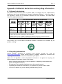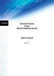
1
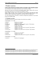
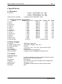
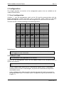
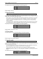
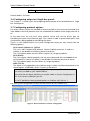
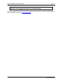
Control Panels
in the
VikinX Sublime series
User manual
Rev. 5
Nevion Europe AS
P.O. Box 1020, 3204 Sandefjord, Norway – Tel: +47 33 48 99 99 – Fax: +47 33 48 99 98
www.nevion.com
VikinX Sublime Control Panels
Rev. 5
Nevion Support
Nevion Europe
1600 Emerson Avenue
Oxnard, CA 93033, USA
P.O. Box 1020
3204 Sandefjord, Norway
Support phone 1: +47 33 48 99 97
Support phone 2: +47 90 60 99 99
Toll free North America: (866) 515-0811
Outside North America: +1 (805) 2478560
Nevion USA
E-mail: [email protected]
See http://www.nevion.com/support/ for service hours for customer support globally.
Revision history
Current revision of this document is the uppermost in the table below.
Rev.
Repl.
Date
Sign
Change description
5
4
2009-10-07
NBS
4
3
3
2
2008-12-05
2008-11-05
NBS
NBS
2
1
0
1
0
-
2008-02-13
2008-01-25
2008-01-03
NBS
NBS
NBS
Added Chapter 2.1.1.
Updated Chapter 5.2 with new information about
Ethernet connectivity.
Added extra information about “A/V Toggle” button
in Chapter 7.
Remover PSU alarm (GPI) information.
Added/corrected GPI (wiring) information.
Added protocol configuration information.
Added description of power pinout.
Added footnotes on extra buttons in Chapter 1.1.
Updated with GPI I/O information.
First release.
nevion.com | 2
VikinX Sublime Control Panels
Rev. 5
Contents
1 Product overview .................................................................................................. 4
1.1 Product versions .............................................................................................................. 4
2 Specifications........................................................................................................ 5
2.1 Mechanics ....................................................................................................................... 5
2.1.1 Weight and power consumption .................................................................................. 5
2.2 Power Supply .................................................................................................................. 5
2.3 Control ............................................................................................................................ 5
2.4 Connection details........................................................................................................... 6
2.4.1 Power Supply pinout .................................................................................................... 6
3 Configuration ....................................................................................................... 7
3.1 Level configuration .......................................................................................................... 7
3.2 Fallback mode ................................................................................................................. 7
3.3 Joystick priority ................................................................................................................ 8
3.4 Power alarm .................................................................................................................... 8
3.5 Joystick mode .................................................................................................................. 8
3.6 Configuring output on Single bus panels ........................................................................ 9
3.7 Configuring protocol options .......................................................................................... 9
4 LED status indication .......................................................................................... 11
4.1 Start-up ......................................................................................................................... 11
4.2 Alarm states ................................................................................................................... 11
4.3 Ethernet states ............................................................................................................... 11
5 Router communication ....................................................................................... 12
5.1 Serial connection ........................................................................................................... 12
5.1.1 Maximum cable length (RS-232) ................................................................................ 12
5.2 Ethernet connection ...................................................................................................... 13
5.2.1 HW limitations ............................................................................................................ 13
5.3 NCB connection ............................................................................................................ 14
5.3.1 Connecting control panels ......................................................................................... 14
5.3.2 Pin-out and cable type ............................................................................................... 14
5.3.3 Termination plug ........................................................................................................ 15
5.3.4 Control bus structure .................................................................................................. 15
5.3.5 Maximum distance between NCB devices .................................................................. 15
6 GPI connections ................................................................................................. 16
7 Control Panel operation ...................................................................................... 17
7.1 Button description ......................................................................................................... 17
General environmental requirements for Nevion equipment .................................. 20
Product Warranty .................................................................................................. 21
Important notes regarding Software in the VikinX Sublime router family range....... 22
Appendix A Materials declaration and recycling information .................................. 23
nevion.com | 3
VikinX Sublime Control Panels
Rev. 5
1 Product overview
Nevion are proud to present the 2nd generation of the compact small and medium routing
switcher family, Sublime. With Sublime, Nevion now provide a stable and proven product
line including the most complete signal format and size offering available.
With the new ultra slim, multi format and flexible product range, Sublime fulfils the most
demanding requirements from the professional broadcast market.
VikinX Sublime provides many of the powerful control features that drove the VikinX
Modular range to success. VikinX Sublime is ideal for general purpose facilities, on-air
routing, mobile outside broadcast applications and sophisticated A/V applications.
This user manual presents the features, installation and operation procedures of the control
panels of the Sublime range.
1.1 Product versions
The following versions of the VikinX Sublime Control Panels are available:
Control Panels – 19” – 1RU:
SL-8XY-CP
SL-8S-CP
SL-8S-CP-GPI
SL-16XY-CP
SL-16D-CP
SL-16S-CP
SL-16S-CP-GPI
SL-32S-CP
SL-32S-CP-GPI
Multi bus X-Y 8x8 panel.
Single bus 8x1 panel.
Single bus 8x1 panel with GPI / Joystick / Tally interface.
Multi bus X-Y 16x16 panel.
Dual bus 16x2 panel.
Single bus 16x1 panel.
Single bus 16x1 panel with GPI / Joystick / Tally interface.
Single bus 32x1 panel.
Single bus 32x1 panel with GPI / Joystick / Tally interface.
Control Panels – 19” – 2RU 1:
SL-32XY-CP
SL-64S-CP
SL-64S-CP-GPI
Multi bus X-Y 32x32 panel.
Single bus 64x1 panel.
Single bus 64x1 panel with GPI / Joystick / Tally interface.
Control Panels – 19” – 4RU 2:
SL-64XY-CP
Multi bus X-Y 64x64 panel.
1
Sublime 2RU Control Panels come with 2 additional, programmable buttons on the bottom left side.
These buttons may be programmed in the same way as any of the other programmable buttons.
2
Sublime 4RU Control Panels come with 6 additional, programmable buttons on the bottom left side.
These buttons may be programmed in the same way as any of the other programmable buttons.
nevion.com | 4
VikinX Sublime Control Panels
Rev. 5
2 Specifications
2.1 Mechanics
Dimensions:
Safety/Emission standards:
HxWxD = 44x483x50mm, (19”, 1RU);
HxWxD = 88x483x50mm, (19”, 2RU);
HxWxD = 176x483x50mm, (19”, 4RU).
Compliant with CE EN55103-1 and 2.
2.1.1 Weight and power consumption
Device
SL-8XY-CP
SL-8S-CP
SL-8S-CP-GPI
SL-16XY-CP
SL-16D-CP
SL-16S-CP
SL-16S-CP-GPI
SL-32XY-CP
SL-32S-CP
SL-32S-CP-GPI
SL-64XY-CP
SL-64S-CP
SL-64S-CP-GPI
SL-PWR-40 (PSU)
Weight, incl. 1x PSU
1.0 kg
1.0 kg
1.2 kg
1.0 kg
1.0 kg
1.0 kg
1.2 kg
1.4 kg
1.0 kg
1.3 kg
2.1 kg
1.4 kg
1.6 kg
0.35 kg
Current +15V Current -15V
300 mA
3 mA
300 mA
3 mA
400 mA
3 mA
300 mA
3 mA
300 mA
3 mA
250 mA
3 mA
400 mA
3 mA
300 mA
3 mA
300 mA
3 mA
400 mA
3 mA
300 mA
3 mA
300 mA
3 mA
400 mA
3 mA
N/A (AC Mains)
Power
5W
5W
6W
5W
5W
4W
6W
5W
5W
6W
5W
5W
6W
2.2 Power Supply
SL-PWR-40
AC Supply voltage range:
AC Mains connector:
DC output:
DC connector:
Status monitoring:
Safety standards:
40W Power Supply Unit.
100-240VAC, 50-60Hz, Max 1.6A.
IEC 320.
+15V, max. 2.2A / -15V, max 1.35A. Maximum 43W.
DB9, female.
Via LED in front of the router/CP.
Compliant with CE EN60950, UL-1950/CSA22.2.
2.3 Control
Standard Features:
Serial port:
Connector(s):
NCB ports:
Connectors (2):
Ethernet port:
Connector:
RS-232 for protocol conversion, to VikinX compact control
protocol, or to third party protocols.
DB9, female.
For integration with VikinX compact router configuration.
RJ45 (1 In / 1 Out)
10/100BaseT Ethernet bus for external router control.
RJ45.
nevion.com | 5
VikinX Sublime Control Panels
Rev. 5
2.4 Connection details
The Sublime routers and control panels have the following service connections on the rear of
each product:
Figure 1: Sublime service connectors.
SYNC:
LOOP:
NCB IN:
NCB OUT:
ETHERNET:
RS 232:
POWER A:
POWER B:
CONFIGURATION:
Not in use on Control Panels.
Not in use on Control Panels.
Network Control Bus Input. The protocol of this bus is described in a
separate manual.
Network Control Bus Output.
10/100Base-T Ethernet bus for external router control.
RS-232 for external control protocols.
±15VDC power connector.
±15VDC power connector, redundant supply.
Configurations switch. See Chapter 3 for further descriptions.
2.4.1 Power Supply pinout
The DB9 power pinout for Sublime routers and Control Panels are as follows;
Pin #
1
2
3
4
5
6
7
8
9
Description
GND
Not connected
Not connected
+15VDC
Not connected
Not connected
Not connected
-15VDC
Not connected
nevion.com | 6
VikinX Sublime Control Panels
Rev. 5
3 Configuration
This chapter provides an overview of the configuration options that are available on the
Sublime Control Panels.
3.1 Level configuration
Switches 1 - 4 on the configuration switch set the CP’s level for communication with the
Router Management System and other units in the NCB system. Panels on the NCB
dedicated to operate with the router must be configured to the same level as that router.
The levels can be switched according to the following pattern:
SW 1
OFF
OFF
OFF
OFF
OFF
OFF
OFF
OFF
ON
ON
ON
ON
ON
ON
ON
ON
SW 2
OFF
OFF
OFF
OFF
ON
ON
ON
ON
OFF
OFF
OFF
OFF
ON
ON
ON
ON
SW 3
OFF
OFF
ON
ON
OFF
OFF
ON
ON
OFF
OFF
ON
ON
OFF
OFF
ON
ON
SW 4
OFF
ON
OFF
ON
OFF
ON
OFF
ON
OFF
ON
OFF
ON
OFF
ON
OFF
ON
Level
1
2
3
4
5
6
7
8
9
10
11
12
13
14
15
16
NCB Address
0
1
2
3
4
5
6
7
8
9
10
11
12
13
14
15
Default level is 1.
It is possible to control more than 1 level with Sublime panel. See Chapter 7.1
(A/V Toggle) for more information.
3.2 Fallback mode
This information is only applicable on GPI versions.
Switch 5 on the configuration switch sets the fallback mode of the GPI panel, either to
dynamic or to hard-set.
This is only useful when the GPI panel is in Joystick release mode, see Chapter
3.5.
−
Dynamic fallback mode. When the GPI is activated the X-point status is saved before
switching. When the GPI is released again, the panel will switch back to the previous
saved X-point status.
−
Hard-set fallback mode. When the GPI is released, the panel will switch to a previously
configured fallback input. The fallback input is configured using the input buttons, see
Chapter 7.1.
nevion.com | 7
VikinX Sublime Control Panels
Rev. 5
The modes can be switched according to the following pattern:
SW 5
OFF
ON
Fallback mode
Hard-set
Dynamic
Default mode is Hard-set.
3.3 Joystick priority
This information is only applicable on GPI versions.
Switch 6 on the configuration switch set the Joystick priority of the GPI panel, either to
release before switch or to switch before release.
−
Release before switch. Used in both GPI and Joystick mode. The activation of a new input
line will have no effect until the previous line is released. If more lines are activated in
sequence, the latest activated one will result in a switching as soon as the previously
active is released.
−
Switch before release. Used in both GPI and Joystick mode. The activation of a new input
line will generate a switching, regardless of how many other lines that are already set.
The priority can be switched according to the following pattern:
SW 6
OFF
ON
Joystick priority
Switch before release
Release before switch
Default mode is Switch before release.
3.4 Power alarm
The power alarm can be switched according to the following pattern:
SW 7
OFF
ON
Power alarm
Disables Power Alarm
Enables Power Alarm
Default setting is Power alarm disabled.
3.5 Joystick mode
This information is only applicable on GPI versions.
Switch 8 on the configuration switch set the Joystick mode of the GPI panel, either to GPI
mode or to Joystick release mode.
−
GPI mode. Releasing the input lines will keep the previous status. Operation of the front
panel is allowed with any number of active GPI-lines simultaneously.
−
Joystick release mode. When all the input lines are released, a default input (either
dynamically chosen or static) is set. The front panel is locked if any of the input lines are
active.
The modes can be switched according to the following pattern:
SW 8
OFF
Joystick mode
GPI mode
nevion.com | 8
VikinX Sublime Control Panels
ON
Rev. 5
Joystick release mode
Default mode is GPI mode.
3.6 Configuring output on Single bus panels
See Chapter 7.1, section Input for configuring default output to be controlled from a Single
bus control panel.
3.7 Configuring protocol options
For various reasons, Nevion has decided to make it possible to turn the extra commands that
were added to the NCB protocol when we introduced the Sublime router range either off or
on.
At the same time, the user must select whether he/she shall use the RS-232 port for
controlling the router or the Ethernet port. This is done in order to prevent both ports from
simultaneously being applied for controlling the router.
There is a new Protocol field in the System Configurator where you may choose from the
following options;
−
NCB without Sublime ext. (RS232)
This is the “old” Compact NCB protocol, without Sublime extensions. If used on a
Sublime, it also disables the Ethernet port of that device.
This is the default option for the Sublime Compact (SC) range of products.
−
NCB (RS232)
This is the regular Sublime protocol, with the extra commands that were added to the
NCB protocol. If used on a Sublime, it also disables the Ethernet port of that device.
This is the default option for the Sublime (SL) range of products.
−
MRP (TCP/IP)
This option is only applicable to the Sublime range. It selects the Ethernet protocol as the
control option, and disables the RS-232 port of that device.
Note that the above selection is only possible if you have Sublime FW rel. 2.1.1
(or newer) installed on your Sublime device.
Note also that the above selection can only be made via System Configurator rel.
3.3.5 (or newer) installed on your PC.
It is NOT possible to select protocol options on Sublimes with HW rev. 1.
Use your System Configurator to verify the HW revision of your Sublime unit:
Figure 2: HW verification in Nevion Configurator.
nevion.com | 9
VikinX Sublime Control Panels
Rev. 5
Right-click the column headers and select the appropriate column to be shown, if
you don’t see the appropriate column in your default display.
For further information about FW releases, please go to the Nevion web site to download, or
check available FW releases: www.nevion.com.
nevion.com | 10
VikinX Sublime Control Panels
Rev. 5
4 LED status indication
4.1 Start-up
The LED located at the front of the control panel indicates the status of the panel. At startup, the LED will alternate between red (R) and green (G) every 500ms for about two
seconds. After the start-up sequence the LED will indicate the Alarm state of the panel.
There are two LEDs located at the Ethernet bus. At start-up the boot loader is searching for
update commands on the serial port for about two seconds. During this sequence both
Ethernet LEDs will be blinking. After the start-up sequence the LEDs will indicate the Ethernet
state.
4.2 Alarm states
The LED can either be red (R), green (G), yellow (Y) or have no light (N).
The LED state is here described with twenty letters, each representing 100ms, which totals to
an alarm sequence of two seconds. The X indicates that the LED keeps the color it has the
moment the alarm sequence begins (green, yellow or no light).
Description
Continuous
green light
Continuous
yellow light
Long red
blinks
One short
red blink
Two short
red blinks
LED state
GGGGG GGGGG GGGGG GGGGG
RXXXX XXXXX XXXXX XXXXX
Alarm
No alarm.
Status is OK.
Unable to
connect to
controller over
Ethernet.
Power is too
low.
Power A failed
XXXXX XXXXX RXRXX XXXXX
Power B failed
YYYYY YYYYY YYYYY YYYYY
RRRRR NNNNN RRRRR NNNNN
Comment
This alarm will be
overwritten by other
alarms
Only active if power
alarm dip is set.
Only active if power
alarm dip is set.
4.3 Ethernet states
The LEDs that are located at the Ethernet bus will after the Start-up sequence indicate the
Ethernet states:
Green
Yellow
On
Valid link
No data
Off / Blinking
No link
Data is transmitted or received
nevion.com | 11
VikinX Sublime Control Panels
Rev. 5
5 Router communication
You gain access to router for communication purposes by connecting either the router’s
serial port to your computer or by using an Ethernet connection.
Do not use both the router’s Ethernet port and RS-232 serial port, or NCB ports,
at the same time. Doing so may cause loss of important communication and
control data.
5.1 Serial connection
Connection can by made trough the serial port(s) of the router; see also Chapter 0 for
connection details.
The communication parameters are configurable. Please refer to the protocol documentation
of the appropriate communication/control protocol.
Example: The protocol parameters of the VikinX Compact routers are as follows:
−
Bit rate 19200 bit/s
−
Data bits 8 bits
−
Stop bits 1
− Parity: No parity
For further details concerning this protocol, please refer to the following manual:
NCB Protocol.pdf.
The DB9 female connector for the serial port(s) of the router has the following pin-out:
Pin #
1
2
3
4
5
6
7
8
9
RS-232 mode
Not in use
Tx
Rx
Not in use
GND
GND
RTS
CTS
Do Not Connect!
Note that if the standard RS-232 cable specification (DCE) is followed:
A cable with Male+Male or Female+Female connectors at the cable ends is used
for Rx/Tx crossed connection, and
A cable with Male+Female connectors at the cable ends is used for a straight
through connection.
5.1.1 Maximum cable length (RS-232)
IEEE has specified the maximum cable length for an RS-232 connection to 15m. Longer
distances can be installed depending on the environmental conditions of the installation site.
It is the responsibility of the installer / user to secure a proper installation of the
RS-232 connection.
nevion.com | 12
VikinX Sublime Control Panels
Rev. 5
5.2 Ethernet connection
The connections follow the standard set by the IEEE 802.3 100BaseTX specification. The
cables that are to be applied should be CAT-5 / CAT-5E standard, or better. It is the
responsibility of the installer / user to secure a proper installation of the Ethernet connection.
All VikinX Sublime routers and IP-based Control Panels are connected together through an
Ethernet Switch.
A VikinX Sublime device has only one physical Ethernet connection. If redundant control is
required, this limitation has to be solved by the control system.
For Ethernet protocol details concerning this router, please refer to the following manual:
Modular Router Control Protocol. This manual can be found on our web site:
http://www.nevion.com.
5.2.1 HW limitations
With the introduction of Sublime controller HW Rev.2, the user has the option of connecting
more than two devices together, without having a Multicon to control the network. See
Chapter 3.7 for verification of the HW revision of your device.
Unless you apply a Multicon as a system controller, the limitations that apply are:
1. One Sublime control panel may connect to a maximum of 4 Sublime routers.
2. One Sublime router may be controlled by a maximum of 4 Sublime control panels.
Exceptions to the above limitations:
A router with a local CP (e.g. SL-V6464-CP) may only connect to 1 other router.
Both routers must be configured with the same address and be of different type
(A+V).
Example: 1x SL-V6464-CP may only control itself + 1x Audio router (AA or AES).
Both routers must be configured with the same address.
16x2 routers that are expanded to NNx2 are using the NCB bus for this purpose.
The total NNx2 router is therefore counted as 1 router in the limitations 1 and 2
above.
From limitations 1 and 2 above, the resulting Ethernet configuration may consist of
maximum 8 devices; 4 routers and 4 control panels, with the exceptions mentioned above.
An example is illustrated in the figure below.
Figure 3: Ethernet connections and configuration.
nevion.com | 13
VikinX Sublime Control Panels
Rev. 5
Refer to the System Configurator User Manual for further information about the
above described configuration/connection options.
It is NOT possible to connect more than 2x Sublimes with HW rev. 1 together via
Ethernet, unless a Multicon is applied as system controller.
5.3 NCB connection
Via the Network Control Bus system several routers and control panels can be
interconnected.
Up to 16 levels of routers, or combinations of routers, can be controlled. The NCB system
and all RS 232 ports interchange the system status. This means that any control system,
either from Nevion, or from a third party manufacturer, connected to any RS 232 port in the
NCB loop, will have access to all communication data on the bus.
5.3.1 Connecting control panels
To get a control panel working with a specific router, configure the control panel to the
same level as the router. Several panels can be configured to control the same router. Panels
can also be connected to a router via the RS-232 interface. Please refer to your control panel
manual for installation.
5.3.2 Pin-out and cable type
VikinX Sublime routers and Control Panels use RJ45 connectors for the Network Control Bus
ports. The following pin-out is used:
Pin #1
Pin #2
Pin #3
Pin #4
Pin #5
Pin #6
Pin #7
Pin #8
Not Connected
Not Connected
Data (retour)
Data
Data
Data (retour)
Not Connected
Not Connected
The following connection example shows connection of 4 VikinX devices with RJ45
connectors and bus termination:
Figure 4: NCB loop configuration.
Note that each device at the end of the chain has a termination plug, indicated
with the letter “T”. This termination plug must be inserted in the correct
connection port. If not, no NCB communication is possible.
nevion.com | 14
VikinX Sublime Control Panels
Rev. 5
5.3.3 Termination plug
The termination plug that is mentioned in the previous chapter is necessary when you want
to avoid closing the loop be a (long) cable.
The termination plug is a standard RJ45 plug with the following internal wiring:
Figure 5: NCB loop termination plug.
As seen in the figure above, Pin 3 is connected to Pin 4, and Pin 5 is connected to Pin 6.
5.3.4 Control bus structure
The Network Control Bus structure follows the standard MIDI bus definition. The NCB is
defined as a closed chain of units. This means that the NCB OUT of the last unit must be
connected to the NCB IN of the first unit in the NCB chain. To avoid problems with the
control of VikinX units the installer/user has to assure that the bus structure is installed
according to this definition.
The total number of VikinX devices in an NCB chain is limited to 50.
5.3.5 Maximum distance between NCB devices
The standard MIDI definition allows a maximum cable length of 200-250 meters between
two devices. Longer distances can be made with MIDI repeater units. To avoid grounding
problems all NCB ports have opto-coupled inputs.
nevion.com | 15
VikinX Sublime Control Panels
Rev. 5
6 GPI connections
This information is only applicable on GPI versions.
The GPI / Joystick / Tally signals are connected to the Sublime Control Panel with GPI options
using DB25 male connectors. Each Sublime CP with GPI I/O has 32 GPI inputs and 32 GPI
outputs available, independent of panel size.
The GPI connectors on the CP are DB25 females.
The following pinout applies:
GPI I/O Channel #
1 and 17
2 and 18
3 and 19
4 and 20
5 and 21
6 and 22
7 and 23
8 and 24
9 and 25
10 and 26
11 and 27
12 and 28
13 and 29
14 and 30
15 and 31
16 and 32
Connector pin #
12
24
23
10
09
21
20
07
06
18
17
04
03
15
14
01
−
Inputs are internally connected to +5V via a pull-up resistor. The inputs will be activated
when pulling them to ground. Ground is available on the following pins: 2, 5, 8, 11, 13,
16, 19, 22, 25 and on the connector chassis.
−
Outputs are of open collector type. An output can switch a maximum load of 100mA at
30V. Any device to be controlled by the GPI outputs (lamp, LED or similar) needs to be
connected to an external supply voltage on one end and to the GPI output on the other
end.
Warning! Do not connect external supply voltages higher than 30V DC.
nevion.com | 16
VikinX Sublime Control Panels
Rev. 5
7 Control Panel operation
All local control panels are completely configurable with the System Configurator, which is
downloadable from the Support pages at http://www.nevion.com/
All local control panels are given a default configuration, which includes the buttons “A/V
Toggle”, “Panel Enable”, “Take on/off” and “Take”. In addition input and output buttons are
preconfigured.
The extra buttons on the 2RU and 4RU panels are not preconfigured. They may
be configured by the user.
Note that GPI functions are not programmable on Sublime GPI CP’s. They have a
fixed, preconfigured function, described earlier in Chapter 3.
7.1 Button description
A/V Toggle
The A/V Toggle button enables/disables audio and video on a specified address. The address
can either be read from the dip switches, or be fixed. The button toggles between three
states.
The user may program more than one A/V Toggle buttons; one button for each
router level that the user wants to control. See Chapter 5.2.1 and the Nevion
Configurator User Manual for further details.
If the button is pressed for more than 1 second, it will go into a fourth state
where both audio and video are disabled.
In this state the button will be dimmed. If the button is pressed for more than 1 second
again, it will enable both audio and video if present.
Button Color
Video Enabled
Audio Enabled
Yellow
Yes
Yes
Green
Yes
No
Red
No
Yes
Dimmed
No
No
If neither audio nor video is present, it will be marked as disabled and the toggle state will
not be used.
Toggle status changes will be stored in flash and used when the panel is powered up later.
When a panel is powered on it will search for connected routers. If no routers are
found the A/V Toggle button will be disabled (no light in the button).
This can happen if the panel is powered up before any routers are connected or if
there is something wrong with the cabling.
To re-enable the A/V Toggle do the following:
1. Activate the Panel Enable button (Green light).
2. Push & Hold the A/V Toggle-button for 2 seconds.
nevion.com | 17
VikinX Sublime Control Panels
Rev. 5
The A/V Toggle-button should now be activated and the light turned on.
Panel Enable
If a Panel Enable button is present, the panel will start up not enabled. In this state the
button will be red and all the other buttons will be disabled. When pressing the button the
panel will be enabled and the color will change to green. A status request will also be sent to
get information on active levels.
If no Panel Enable button is present, the panel will start up enabled.
Take on/off
The Take on/off button enables or disables the Take button. If no take button is defined,
Take on/off is always off. On first start-up the take button is enabled. Later it will read the last
status from the flash memory.
Activating a GPI I/O will not influence the Take on/off function, nor will a Take
on/off function influence the activation of a GPI I/O function.
Take
The Take buttons LED is normally off. If the Take on/off button is set to “on”, no commands
will be sent from the panel until the Take button is pressed. The last selected buttons and the
take button will blink, until the Take button is pressed and the command is sent from the
panel.
Activating a GPI I/O will not influence the Take function, nor will a Take function
influence the activation of a GPI I/O function.
Output
An Output button is used for selecting an output. Selecting an output activates it, so that it is
switched to the next input that is selected.
Input
An Input button switches the active output to the selected input. If the Take button is
enabled, the switch will not be executed until the Take button is pressed.
When switching using the Input button, all enabled audio- and video-levels will be switched
from the selected input to the active output.
The Input button can also be used to select the active output. This is useful on
single bus panels. It requires that a Panel Enable button is present. When the
panel is enabled, press the Panel Enable button and hold it while selecting the
active output by pressing an Input button. Then release the Panel Enable button.
The panel will now be disabled. Press the Panel Enable button again to enable it.
Note that, unlike the buttons on the front of the panel, GPI inputs 1-32 cannot
be reconfigured to represent other inputs, i.e. they are fixed inputs (1-32),
operating on the selected output.
XY
An Input to Output (XY) button switches a preset input to a preset output on all enabled
audio- and video-levels. If the Take button is enabled, the switch will not be executed until
the Take button is pressed.
nevion.com | 18
VikinX Sublime Control Panels
Rev. 5
The maximum router size(s) that may be controlled without Multicon is formed
by IN#1-128 and OUT#1-64 (router size: 128x64). This size limitation is
regardless of the number of routers the control panel(s) is/are controlling.
See also the limitations 1 and 2 in Chapter 5.2.1.
Salvo
A Salvo button switches a sequence of cross points. This is done even if the specified audioor video-level is disabled.
Maximum Salvo size that may be configured without Multicon is limited to 128
X-points.
Lock
A Lock Toggle button toggles the lock-status on the active output on all enabled audio- and
video-levels. If the active output on any of the enabled levels is locked before pressing the
button, they will be unlocked. If not the active output on all enabled levels will be locked. A
locked output can’t be switched.
nevion.com | 19
VikinX Sublime Control Panels
Rev. 5
General environmental requirements for Nevion equipment
1.
2.
-
The equipment will meet the guaranteed performance specification under the
following environmental conditions:
Operating room temperature range: 0°C to 45°C
Operating relative humidity range:
<95% (non-condensing)
The equipment will operate without damage under the following environmental
conditions:
Temperature range:
-10°C to 55°C
Relative humidity range:
<95% (non-condensing)
nevion.com | 20
VikinX Sublime Control Panels
Rev. 5
Product Warranty
The warranty terms and conditions for the product(s) covered by this manual follow the
General Sales Conditions by Nevion, which are available on the company web site:
www.nevion.com
nevion.com | 21
VikinX Sublime Control Panels
Rev. 5
Important notes regarding Software in the VikinX Sublime router
family range
This product utilizes software components that are licensed with open source licenses. The
source code for these components and our modifications are available from:
http://labs.nevion.com/open-source/
OpenTCP includes software developed by Viola systems (http://www.violasystems.com/).
nevion.com | 22
VikinX Sublime Control Panels
Rev. 5
Appendix A Materials declaration and recycling information
A.1 Materials declaration
For product sold into China after 1st March 2007, we comply with the “Administrative
Measure on the Control of Pollution by Electronic Information Products”. In the first stage of
this legislation, content of six hazardous materials has to be declared. The table below
shows the required information.
Toxic or hazardous substances and elements
組成名稱
Part Name
鉛
汞
镉
六价铬
多溴联苯
多溴二苯醚
Lead Mercury Cadmium Hexavalent Polybrominated Polybrominated
(Hg)
biphenyls
diphenyl ethers
(Pb)
(Cd)
Chromium
(PBB)
(PBDE)
(Cr(VI))
All products
referred to in
Chapter 1.1
O
O
O
O
O
O
SL-PWR-40
O
O
O
O
O
O
O: Indicates that this toxic or hazardous substance contained in all of the homogeneous materials for
this part is below the limit requirement in SJ/T11363-2006.
X: Indicates that this toxic or hazardous substance contained in at least one of the homogeneous
materials used for this part is above the limit requirement in SJ/T11363-2006.
Parts without any of the above mentioned hazardous substances are indicated by the
product marking:
A.2 Recycling information
Nevion provides assistance to customers and recyclers through our web site
http://www.nevion.com/. Please contact Nevion’s Customer Support for assistance with
recycling if this site does not show the information you require.
Where it is not possible to return the product to Nevion or its agents for recycling, the
following general information may be of assistance:
−
Before attempting disassembly, ensure the product is completely disconnected from
power and signal connections.
−
All major parts are marked or labeled to show their material content.
−
Depending on the date of manufacture, this product may contain lead in solder.
−
Some circuit boards may contain battery-backed memory device.
nevion.com | 23