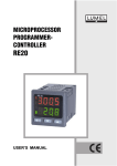
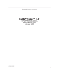
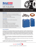
1
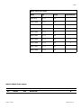
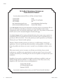
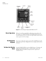
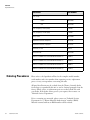
Class “100” Clean Room Ovens
Operating Manual and Parts List LT1476X7 Rev. 0
Visit us online to register your warranty
www.thermoscientific.com/warranty
Preface
Models covered in this manual
Models
Size
Voltage
With HEPA Filter
3490M (6879)
2.6 cu ft
120V
3490M-1 (6880)
2.6 cu ft
240V
3492M (6881)
2.6 cu ft
120V
3492M-1 (6882)
2.6 cu ft
240V
3494M-1 (6883)
2.6 cu ft
240V
3495M-1 (6884)
3.6 cu ft
240V
3496M-1 (6885)
2.8 cu ft
240V
X
3497M-1 (6886)
2.8 cu ft
240V
X
3498M-1 (6887)
4.6 cu ft
240V
3499M-1 (6888)
4.6 cu ft
240V
MANUAL NUMBER LT1476X7 (7006879)
0
--
6/4/10
Transfer to Marietta (was LT1476X7 5/30/08)
ccs
REV
ECR/ECN
DATE
DESCRIPTION
By
Thermo Scientific
Clean Room Oven
i
Preface
Important Read this instruction manual. Failure to read, understand and follow the instructions in this manual
may result in damage to the unit, injury to operating personnel, and poor equipment performance. ▲
Caution All internal adjustments and maintenance must be performed by qualified service personnel. ▲
Material in this manual is for information purposes only. The contents and the product it describes are subject to
change without notice. Thermo Fisher Scientific makes no representations or warranties with respect to this
manual. In no event shall Thermo be held liable for any damages, direct or incidental, arising out of or related to
the use of this manual.
©2010 Thermo Scientific. All rights reserved.
ii
Clean Room Oven
Thermo Scientific
Preface
Important operating and/or maintenance instructions. Read the accompanying text carefully.
Potential electrical hazards. Only qualified persons should perform procedures associated with this
symbol.
Equipment being maintained or serviced must be turned off and locked off to prevent possible injury.
Hot surface(s) present which may cause burns to unprotected skin, or to materials which may be
damaged by elevated temperatures.
Marking of electrical and electronic equipment, which applies to electrical and electronic equipment
falling under the Directive 2002/96/EC (WEEE) and the equipment that has been put on the market
after 13 August 2005.
This product is required to comply with the European Union’s Waste Electrical & Electronic
Equipment (WEEE) Directive 2002/96/EC. It is marked with the WEEE symbol. Thermo Fisher
Scientific has contracted with one or more recycling/disposal companies in each EU Member State
European Country, and this product should be disposed of or recycled through them. Further
information on Thermo’s compliance with this directive, the recyclers in your country and
information on Thermo products will be available at www.thermofisher.com.
✔
Always use the proper protective equipment (clothing, gloves, goggles, etc.)
✔ Always dissipate extreme cold or heat and wear protective clothing.
✔ Always follow good hygiene practices.
✔ Each individual is responsible for his or her own safety.
Thermo Scientific
Clean Room Oven
iii
Preface
Do You Need Information or Assistance on
Thermo Scientific Products?
If you do, please contact us 8:00 a.m. to 6:00 p.m. (Eastern Time) at:
1-740-373-4763
1-800-438-4851
1-877-213-8051
http://www.thermoscientific.com
[email protected]
Direct
Toll Free, U.S. and Canada
FAX
Internet Worldwide Web Home Page
Service E-Mail Address
Our Sales Support staff can provide information on pricing and give you quotations. We can
take your order and provide delivery information on major equipment items or make
arrangements to have your local sales representative contact you. Our products are listed on the
Internet and we can be contacted through our Internet home page.
Our Service Support staff can supply technical information about proper setup, operation or
troubleshooting of your equipment. We can fill your needs for spare or replacement parts or
provide you with on-site service. We can also provide you with a quotation on our Extended
Warranty for your Thermo Scientific products.
Whatever Thermo Scientific products you need or use, we will be happy to discuss your
applications. If you are experiencing technical problems, working together, we will help you
locate the problem and, chances are, correct it yourself...over the telephone without a service
call.
When more extensive service is necessary, we will assist you with direct factory trained
technicians or a qualified service organization for on-the-spot repair. If your service need is
covered by the warranty, we will arrange for the unit to be repaired at our expense and to your
satisfaction.
Regardless of your needs, our professional telephone technicians are available to assist you
Monday through Friday from 8:00 a.m. to 6:00 p.m. Eastern Time. Please contact us by
telephone or fax. If you wish to write, our mailing address is:
Thermo Fisher Scientific
401 Millcreek Road, Box 649
Marietta, OH 45750
International customers, please contact your local Thermo Scientific distributor.
iv
Clean Room Oven
Thermo Scientific
Table of Contents
Thermo Scientific
Section 1
Description . . . . . . . . . . . . . . . . . . . . . . . . . . . . . . . . . . . . . . . . . . . . . . . . . .1-1
Section 2
Safety Information . . . . . . . . . . . . . . . . . . . . . . . . . . . . . . . . . . . . . . . . . . . .2-1
Section 3
Specifications . . . . . . . . . . . . . . . . . . . . . . . . . . . . . . . . . . . . . . . . . . . . . . .3-1
Section 4
Unpacking and Installation . . . . . . . . . . . . . . . . . . . . . . . . . . . . . . . . . . . .4-1
Location . . . . . . . . . . . . . . . . . . . . . . . . . . . . . . . . . . . . . . . . . . . . . . .4-1
Stacking Units . . . . . . . . . . . . . . . . . . . . . . . . . . . . . . . . . . . . . . . . . .4-1
Electrical Power . . . . . . . . . . . . . . . . . . . . . . . . . . . . . . . . . . . . . . . . .4-2
Baking-Out the Oven . . . . . . . . . . . . . . . . . . . . . . . . . . . . . . . . . . . .4-2
Cleaning . . . . . . . . . . . . . . . . . . . . . . . . . . . . . . . . . . . . . . . . . . . . . . .4-2
Shelf Installation . . . . . . . . . . . . . . . . . . . . . . . . . . . . . . . . . . . . . . . .4-2
Leveling . . . . . . . . . . . . . . . . . . . . . . . . . . . . . . . . . . . . . . . . . . . . . . .4-2
Door Adjustment . . . . . . . . . . . . . . . . . . . . . . . . . . . . . . . . . . . . . . . .4-3
Gas Connection . . . . . . . . . . . . . . . . . . . . . . . . . . . . . . . . . . . . . . . . .4-3
Latch Adjustment -Door Hard to Open . . . . . . . . . . . . . . . . . . . . . .4-4
Latch Adjustment -Door Against Gasket . . . . . . . . . . . . . . . . . . . . . .4-4
Latch Adjustment -Heating Door Opens . . . . . . . . . . . . . . . . . . . . .4-5
Section 5
Features . . . . . . . . . . . . . . . . . . . . . . . . . . . . . . . . . . . . . . . . . . . . . . . . . . . . .5-1
Control Panel . . . . . . . . . . . . . . . . . . . . . . . . . . . . . . . . . . . . . . . . . . .5-1
Clean Room Oven
v
Table of Contents
vi
Clean Room Oven
Section 6
8 Segment & 4x16 Segment Programmable Models . . . . . . . . . . . . . .6-1
To View the Display Units . . . . . . . . . . . . . . . . . . . . . . . . . . . . . . . . .6-2
To Change the Setpoint . . . . . . . . . . . . . . . . . . . . . . . . . . . . . . . . . . .6-2
Basic Operation . . . . . . . . . . . . . . . . . . . . . . . . . . . . . . . . . . . . . . . . .6-2
To View the % Output Power . . . . . . . . . . . . . . . . . . . . . . . . . . . . . .6-3
Buttons and Indicators . . . . . . . . . . . . . . . . . . . . . . . . . . . . . . . . . . . .6-3
Controller Parameters . . . . . . . . . . . . . . . . . . . . . . . . . . . . . . . . . . . . .6-4
Alarms . . . . . . . . . . . . . . . . . . . . . . . . . . . . . . . . . . . . . . . . . . . . . . . .6-6
Single Setpoint Controller Operation . . . . . . . . . . . . . . . . . . . . . . . . .6-7
Sensor Break Protection . . . . . . . . . . . . . . . . . . . . . . . . . . . . . . . . . . .6-7
Programming the Controller . . . . . . . . . . . . . . . . . . . . . . . . . . . . . . .6-7
Creating a New or Editing an Existing Program . . . . . . . . . . . . . . .6-7
Hb: Holdback . . . . . . . . . . . . . . . . . . . . . . . . . . . . . . . . . . . . . . . . .6-8
CYC.n: Setting the Number of Cycles . . . . . . . . . . . . . . . . . . . . . .6-9
dwL.U: Setting Dwell Units . . . . . . . . . . . . . . . . . . . . . . . . . . . . . .6-9
rmP.U: Setting Ramp Units . . . . . . . . . . . . . . . . . . . . . . . . . . . . . . .6-9
Setting the Segment Type . . . . . . . . . . . . . . . . . . . . . . . . . . . . . . .6-10
Setting the Target Setpoint . . . . . . . . . . . . . . . . . . . . . . . . . . . . . .6-13
Cancelling a Program . . . . . . . . . . . . . . . . . . . . . . . . . . . . . . . . . . . .6-13
Holding a Program . . . . . . . . . . . . . . . . . . . . . . . . . . . . . . . . . . . . . .6-13
Running a Program . . . . . . . . . . . . . . . . . . . . . . . . . . . . . . . . . . . . .6-13
Tuning Your Oven . . . . . . . . . . . . . . . . . . . . . . . . . . . . . . . . . . . . . .6-14
Tuning Error . . . . . . . . . . . . . . . . . . . . . . . . . . . . . . . . . . . . . . . . .6-14
Gain Scheduling . . . . . . . . . . . . . . . . . . . . . . . . . . . . . . . . . . . . . . . .6-14
Autotuning . . . . . . . . . . . . . . . . . . . . . . . . . . . . . . . . . . . . . . . . . .6-15
Adaptive Tuning . . . . . . . . . . . . . . . . . . . . . . . . . . . . . . . . . . . . . .6-16
Section 7
Maintenance . . . . . . . . . . . . . . . . . . . . . . . . . . . . . . . . . . . . . . . . . . . . . . . .7-1
Door Gasket Repair . . . . . . . . . . . . . . . . . . . . . . . . . . . . . . . . . . . . . .7-1
Complete Gasket Replacement . . . . . . . . . . . . . . . . . . . . . . . . . . . . .7-2
Filter Replacement . . . . . . . . . . . . . . . . . . . . . . . . . . . . . . . . . . . . . . .7-2
Parts Replacement/General . . . . . . . . . . . . . . . . . . . . . . . . . . . . . . . .7-2
Section 8
Replacement Parts . . . . . . . . . . . . . . . . . . . . . . . . . . . . . . . . . . . . . . . . . . .8-1
Ordering Procedures . . . . . . . . . . . . . . . . . . . . . . . . . . . . . . . . . . . . .8-2
Thermo Scientific
Section 1
Description
This advanced series of Ultra-Clean 100 ovens incorporates programmercontroller which can be conveniently and easily operated by the user from
a front panel keyboard. Mnemonics in the display area of the programmercontroller keeps the user informed of the parameters which are being acted
upon. An additional option allows the unit to be operated in either
automatic or manual mode.
Mechanical air circulation provides optimum temperature uniformity and
rapid recovery after door openings.
Two systems protect oven contents against overheating. An alarm setpoint
programmed in the controller initiates a visual signal in the event the
actual temperature exceeds the limit. In addition, a second system is an
independent hydraulic thermostat set by the operator to a temperature
slightly higher than the maximum operating temperature. This thermostat
is a mechanical backup to protect contents in the unlikely event the
programmer-controller experiences a failure. A red status lamp warns of
the overtemperature condition.
Thermo Scientific
Clean Room Oven
1-1
Section 2
Safety Information
Your Thermo Scientific Class “100” Clean Room Oven has been designed
with function, reliability, and safety in mind. It is your responsibility to
install it in conformance with local electrical codes. It is most important
that the user follow installation instructions exactly as written. Failure to
do so is likely to lead to improper operation, erroneous calibrations and
possible damage to the equipment. Do not attempt operation without this
information.
Thermo Scientific
Clean Room Oven
2-1
Section 3
Specifications
Power Requirements
All models accept 50 Hz or 60 Hz current.
Model
Volts AC
Watts
Amps
Heaters
3490M, 3492M
120
1900
15.8
2
3490M-1, 3492M-1
220/240
1900
7.9
2
3494M-1, 3495M-1
220/240
3100
12.9
2
3496M-1, 3497M-1
220/240
3100
12.9
2
3498M-1, 3499M-1
220/240
3100
12.9
2
Temperature Range
Slightly above ambient to +250°C.
Temperature Control
Model . . . . . . . . . . . . . . . . . . . . . . . . . . . . .@100°C
3490M, -1, 3492M-1 . . . . . . . . . . . . . . . . . . .±0.1°C
3494M-1, 3495M-1 . . . . . . . . . . . . . . . . . . . .±0.1°C
3496M-1, 3497M-1 . . . . . . . . . . . . .±0.2°C (@90°C)
3498M-1, 3499M-1 . . . . . . . . . . . . . . . . . . . .±0.1°C
Temperature Uniformity
Model . . . . . . . . . . . . . . . . . . . . . . . . . . . . .@100°C
3490M, -1, 3492M-1 . . . . . . . . . . . . . . . . . .±1.0°C
3494M-1, 3495M-1 . . . . . . . . . . . . . . . . . . .±1.0°C
3496M-1, 3497M-1 . . . . . . . . . . . .±1.5°C (@90°C)
3498M-1, 3499M-1 . . . . . . . . . . . . . . . . . . .±1.0°C
Thermo Scientific
@200°C
±0.2°C
±0.2°C
±0.2°C
@200°C
±2.0°C
±2.0°C
±2.0°C
Clean Room Oven
3-1
Section 3
Specifications
Temperature Rise Times
3490M, -1, 3492M-1 . . . . . . . . . . . . . .22.0 minutes
3494M-1, 3495M-1 . . . . . . . . . . . . . . .18.0 minutes
3496M-1, 3497M-1 .1.0 minutes (ambient to 90°C)
3498M-1, 3499M-1 . . . . . . . . . . . . . . .20.5 minutes
Temperature Recovery Time of Load
3490M, -1, 3492M-1 . . . . . . . . . . . . . . . . .8 minutes
3494M-1, 3495M-1 . . . . . . . . . . . . . . . . . .4 minutes
3496M-1, 3497M-1 . . . . . . . . . . . . . . . . .11 minutes
(@90°C: after 1 min., door opening of 90 degrees)
3498M-1, 3499M-1 . . . . . . . . . . . . . . . . . .7 minutes
Method
Door open 90° for 1 minute. Oven loaded with 9, 4" wafer boats filled
with wafers and evenly distributed in the oven. A thermocouple measured
wafer temperature in the center wafer boat. Time recorded equals elapsed
time for wafer temperature to reach 90% of setpoint (150°C).
Note Performance measured under controlled laboratory conditions. Your
oven's performance may be slightly different, depending on application. ▲
Dimensions
3490M, -1, 3492M-1
Interior: 13"W x 18"D x 19-1/2"H (33 x 46 x 50 cm)
Exterior : 21-5/8"W x 24-1/4"D x 35"H (55 x 62 x 89 cm)
Capacity: 2.6 cubic feet
3494M-1, 3495M-1
Interior: 18"W x 18"D x 19-1/2"H (46 x 46 x 50 cm)
Exterior: 26-5/8"W x 24-1/4"D x 35"H (68 x 62 x 89 cm)
Capacity: 3.6 cubic feet
3-2
Clean Room Oven
Thermo Scientific
Section 3
Specifications
Dimensions (continued)
3496M-1, 3497M-1
Interior: 14"W x 18"D x 19-1/2"H (36 x 46 x 50 cm)
Exterior: 26-5/8"W x 24-1/4"D x 35"H (68 x 62 x 89 cm)
Capacity: 2.8 cubic feet
3498M-1, 3499M-1
Interior: 23"W x 18"D x 19-1/2"H (58 x 46 x 50 cm)
Exterior: 31-5/8"W x 24-1/4"D x 35"H (80 x 62 x 89 cm)
Capacity: 4.6 cubic feet
Weight (net)
3490M, -1, 3492M-1: 180 lbs. ( 81.8 kg)
3494M-1, 3495M-1: 220 lbs. (100.0 kg)
3496M-1, 3497M-1: 202 lbs. ( 91.8 kg)
3498M-1, 3499M-1: 234 lbs. (106.4 kg)
Environmental Conditions
Pollution Degree: 2
Installation Category: II
Altitude: 2000 meters MSL (mean sea level)
Humidity: 80% maximum, non-condensing
Electrical supply: 120VAC or 240VAC
Voltage tolerance: ±10% of normal rated line
Temperature: 15°C to 40°C
Product usage: This product is intended for use indoors only.
Thermo Scientific
Clean Room Oven
3-3
Section 4
Unpacking and Installation
The shipping carton should be inspected upon delivery. When received,
carefully examine for any shipping damage before unpacking. If damage is
discovered, the delivering carrier should both specify and sign for the
damage on your copy of the delivery receipt.
Open the carton carefully making certain that all parts are accounted for
before packaging materials are discarded. After unpacking, if damage is
found, promptly report it to the carrier and request a damage inspection
promptly.
Important Failure to request an inspection of damage within a few days
after receipt of shipment absolves the carrier from any liability for damage.
Call for a damage inspection promptly.
BE ADVISED: Ovens must be cleaned and baked-out prior to use in clean
rooms.
Note Disconnect unit from the power source when not in use. ▲
Location
Stacking Units
Place the oven where it is to be operated, in an area away from drafts.
Provide enough clearance to allow free air movement around the oven.
Leave clearance at the rear for gas connection and adjustment of air vent.
Position the unit with room for 90° of door opening to the right. The oven
must not be placed on a combustible surface.
Warning These ovens should not be placed one on top of the other
because:
1) There is danger of the oven on top being accidentally knocked over
with possibility of serious injury and property damage;
2) Heat from oven below can damage control panel components of
oven above with possible resulting electrical short and fire.
To arrange ovens vertically, order optional space saver stacking rack (Model
3480-2). ▲
Thermo Scientific
Clean Room Oven
4-1
Section 4
Unpacking and Installation
Leveling
Shelf Installation
Cleaning
The oven should be level, though its operation does not depend on this.
Do not remove the oven’s rubber feet - they are necessary for proper
ventilation; removing the rubber feet may also cause erratic temperature
control and damage to the electronic components.
Install shelf guides in desired locations along the inside sides of the oven.
Make sure the pair of guides for each shelf are at the same level. Each guide
has 2 sets of tabs. Insert the top tabs first, then the bottom tabs. Slide
shelves into place.
The following procedure is based on test information and a survey of
methods currently used by microchip manufacturers.
•
The person cleaning the oven prior to clean room use should wear
disposable polyethylene gloves to prevent skin oils from contaminating
the oven surfaces.
•
Use a lint-free soft paper manufactured for clean room maintenance.
•
Remove shelves, floor and inside side walls from oven and clean
thoroughly. Clean interior chamber, including heaters, blower wheel
and, very gently, the sensor tube.
•
Move the oven into the clean room and follow installation procedures,
noting that it must be cleaned AGAIN before use.
Baking-Out the Oven
After installing the shelves, bake the empty oven with a steady air exchange
until particle count is reduced to an acceptable level. For working
temperatures about 200°C, bake 2 to 3 hours at 200°C.
Electrical Power
Turn the power switch (on the left side of the front panel) to OFF-the
bottom half of the rocker pushed in. Plug the oven into an electrical outlet
providing the power that is specified on the oven nameplate.
4-2
Clean Room Oven
Thermo Scientific
Section 4
Unpacking and Installation
Gas Connection
Inert gas, such as nitrogen, can be injected into the chamber to flush out
impurities. The gas inlet, on the back of the oven, is a 1/8-inch NPT pipe.
Connect Tygon® R-3603 tubing to this pipe and to the dual regulator on
the gas source. Leave the gas turned off until the oven is being operated.
If the oven is to be operated without gas, keep the inlet capped-DO NOT
USE THE PLASTIC SHIPPING CAP.
Warning Inject only an inert gas into the oven. The use of any other type
gas may lead to fire or explosion and serious injury or death and property
damage. ▲
Door Adjustment
During shipping, the oven door may have been knocked out of line. The
following procedure will correct door-to-body and door-to-gasket
misalignment.
1. Lay the unit on its back. If exhaust and purging ports are fitted,
support the unit on 2' x 4's to protect these components.
2. Remove the pivot bolt and flat washer from the top door hinge.
3. Unlatch the door handle to release the door, then slide the door out
and off the bottom hinge pivot bolt to gain access to hinge screws.
4. Slightly loosen hinge screws on top and bottom hinges, so hinges
require firm hand pressure to reposition. DO NOT REMOVE
HINGE SCREWS - complete removal of screws will make it extremely
difficult to reassemble the hinge.
5. Replace the door on the bottom hinge pin and fit the door in place.
Loosen the bottom hinge pivot bolt with an open-end wrench. Replace
the top hinge pivot bolt and set it to be finger-tight.
6. Align the door to the body-top, bottom and sides.
7. Remove the top hinge pivot-bolt again, noting the position of properly
aligned hinges. Remove the door carefully without moving the hinges
out of position.
8. Tighten all hinge screws VERY securely.
9. Replace door on bottom hinge pivot bolt. Replace the top pivot bolt
and washer. Tighten top and bottom hinge pivot bolts VERY securely
to maintain proper alignment.
Thermo Scientific
Clean Room Oven
4-3
Section 4
Unpacking and Installation
Latch Adjustment Door Against Gasket
If the door does not fit snug against the gasket, follow the procedure below
to adjust latch.
1. Open the door. Use a 5/64" Allen wrench to remove the Allen setscrew
from the door strike assembly.
2. Rotate the catch mechanism clockwise to shorten length and thereby
bring door closer to body of oven. The number of turns will have to be
estimated.
3. Re-insert and tighten the Allen setscrew securely.
4. Repeat this procedure as necessary to achieve a tight seal.
Latch Adjustment Door Hard to Open
If the door is too hard to open, follow the procedure below to adjust the
latch.
1. Open the door. Use 5/64" Allen wrench to remove the Allen setscrew
from the door strike assembly.
2. Rotate catch mechanism counterclockwise to increase length and,
thereby, position door a little farther away from the body of the oven.
The number of turns will have to be estimated. Reinsert and tighten
Allen setscrew securely.
3. Repeat if necessary to achieve satisfactory operation.
Allen Setscrew
Figure 4-1. Door Strike Mechanism
4-4
Clean Room Oven
Thermo Scientific
Section 4
Unpacking and Installation
Latch Adjustment Heating Door Opens
If the door opens while oven is heating, follow the procedure below to
adjust the latch. The door will have to be adjusted to close more easily to
allow for the expansion occurring during heating.
1. Open the door. Use 5/64" Allen wrench to remove the Allen setscrew
from the door strike assembly.
2. Rotate catch mechanism counterclockwise to increase length and,
thereby, position door a little farther away from the body of the oven.
The number of turns will have to be estimated. Re-insert and tighten
Allen setscrew securely.
3. Repeat if necessary to achieve satisfactory operation.
Depending on operating temperature, the procedure may have to be
repeated to ensure proper door operation.
Thermo Scientific
Clean Room Oven
4-5
Section 5
Features
AL1
Power
AL2
REM
MAN
A-T
Hi-Limit
SP
OP
TIME
On
RAMP
DWELL
HOLD
Off
RUN
HOLD
1
2
3
4
REM
P
5
Figure 5-1. Control Panel
Control Panel
1. Power Switch: Turns all power to the unit on or off.
2. Power Switch Status Lamp: When power is on, this green lamp is lit.
3. Hi-Limit Thermostat: This hydraulic type thermostat provides
mechanical overtemperature back-up control if the temperature
programmer-controller should fail.
4. Hi-Limit Thermostat Status Lamp: When lit, this red lamp signals that
the temperature is exceeding the hi-limit setpoint established by the
user.
5. Programmer-Controller: 4-button operation controller allows user to
set and control operating temperature and program ramp-to-setpoint
procedures (operating details follow in the upcoming OPERATION
section).
Thermo Scientific
Clean Room Oven
5-1
8 Segment & 4x16 Segment
Programmable Models
Section 6
The 8 segment programmable controller consists of a microprocessor
based three-mode PID (Proportional, Integral, Derivative), programmable
temperature controller with over-temperature protection and appropriate
output switching devices to control the oven. The digital readout
continuously displays chamber (upper display) and setpoint (lower display)
temperatures unless the SCROLL or PAGE button is depressed. The
programmable controller can be used as a single setpoint controller or as a
programmable controller. The 8 segment digital model enables eight
segments of programming.
The 4x16 segment programmable controller consists of a microprocessor
based three-mode PID (Proportional, Integral, Derivative), programmable
temperature controller with over-temperature protection and appropriate
output switching devices to control the oven. The digital readout
continuously displays chamber (upper display) and setpoint (lower display)
temperatures unless the SCROLL or PAGE button is depressed. The
programmable controller can be used as a single setpoint controller or as a
programmable controller. The 4 program controller has four 16 segment
programs.
Note The controller will return to the HOME DISPLAY if left idle for
more than a few seconds. ▲
Note Once the desired parameter has been selected, depressing either the
UP or DOWN button will change the parameter value. In all cases, the
value shown on display is the current working value of that parameter. ▲
Thermo Scientific
Clean Room Oven
6-1
Section 6
Programmable Models
AUTO/MAN
Button
Output 1
Display
Window
Upper
Display
Lower
Display
RUN/HOLD
Button
UP ARROW
Button
PAGE
Button
SCROLL
Button
DOWN ARROW
Button
Figure 6-1. 4x16 & 8 Segment Programmable Models with OTP
Basic Operation
When the controller is turned ON, it will perform a short self-test and
then change to the HOME DISPLAY. The HOME DISPLAY shows the
measured temperature (process value) in the upper display and the desired
value (setpoint) in the lower display.
To Change the
Setpoint
If you want to change the setpoint, press the UP or DOWN button until
the desired setpoint value is displayed in the lower display and then release
the button.
To View the Display
Units
6-2
Clean Room Oven
From the HOME DISPLAY, press the SCROLL button. The display will
briefly show the temperature units in °C/F/K and then return to the
HOME DISPLAY (if a different temperature unit is required, call
Technical Services).
Thermo Scientific
Section 6
Programmable Models
To View the % Output
Power
From the HOME DISPLAY, press the SCROLL button twice. This value
is a read-only value and cannot be changed.
Buttons and
Indicators
OP1 (Output 1): illuminates when the heating output of the temperature
controller is on.
AUTO/MAN: (Auto/Manual Mode): when the controller is in the
automatic mode the output automatically adjusts to keep the temperature
or process value at the setpoint. The “AUTO” light will illuminate. The
manual mode has been disabled through factory configuration. Call
Technical Services for further information.
RUN/HOLD (Run/Hold button):
•
Starts a program when pressed once—RUN light illuminates.
•
Holds a program when pressed again—HOLD light illuminates.
•
Cancels hold and continues running when pressed again—HOLD
light is off and RUN light illuminates.
•
Exits a program when the button is held down for two seconds—
RUN and HOLD lights are off.
•
At the end of a program the RUN light will flash.
•
During holdback the HOLD light will flash.
PAGE button: allows you to choose a parameter from a list of parameters.
SCROLL button: allows you to choose a parameter within a list of
parameters.
UP button: allows you to increase the value in the lower display.
DOWN button: allows you to decrease the value in the lower display.
Thermo Scientific
Clean Room Oven
6-3
Section 6
Programmable Models
Controller Parameters
Home Display
°C: measured temperature in Celsius. Temperature units can not be
changed without entering the configuration. Contact Technical
Services if a different temperature unit is required.
OP: % output power demand; displayed in lower display (cannot be
changed).
C.id: Controller identification number.
PrG: Program number (displayed when a program is running; 4x16
programmable models only.)
IdHi: Deviation High Alarm
tunE: One-shot autotune enable.
run LiSt (Program Run List)
PrG: Currently running program (only used on 4x16 programmable
models)
StAt: Displays the program status [OFF, run (running active program),
hoLd (program on hold), HbAc (waiting for process to catch up),
End (program completed)] in the lower display. The controller will
default to “OFF.”
FASt: Fast run through program (no/YES). The controller will default
to “no.”
SEG.d: Flash active segment type in the lower display of the home
display (no/YES). The controller will default to “no.”
ProG LiSt (Program Edit List)
PrG.n: Press the UP or DOWN ARROW to select the program
number (program number will be displayed in lower display on
4x16 programmable models only.)
Hb: Press the UP or DOWN ARROW to select the holdback type
[OFF (disables holdback), Lo (deviation low holdback), Hi
(deviation high holdback) or bAnd (deviation band holdback)] for
the entire program. The controller will default to “OFF.”
6-4
Clean Room Oven
Thermo Scientific
Section 6
Programmable Models
Controller Parameters
(continued)
Hb.U: Press the UP or DOWN ARROW to select the holdback value
(in display units).
rmP.U: Press the UP or DOWN ARROW to toggle between ramp
units (SEc, min or Hour). Controller will default to “SEc.”
dwL.U: Press the UP or DOWN ARROW to toggle between dwell
units (SEc, min or Hour). Controller will default to “SEc.”
Cyc.n: Press the UP or DOWN ARROW to set the number of
program cycles (1 to 999 or cont). The controller will default to
“cont.”
SEG.n: Press the UP or DOWN ARROW to select the segment
number (1-8 in 8 segment models, 1-16 in 4x16 models).
tYPE: Press the UP or DOWN ARROW to select the segment type
[End (end of program), rmP.r = ramp rate (ramp to a specified
setpoint at a set rate), rmp.t = ramp time (ramp to a specified
temperature in a set time), dwEll (to maintain a constant
temperature for a set time), StEP (climb instantaneously from
current to specified temperature), cALL (to call a program as a
subroutine, available only on 4x16 programmable models)]. The
controller will default to “End.” Other parameters used with tYPE
include; tGt target setpoint), Rate (rate of temperature increase)
and dur (time to target setpoint or time to dwell).
End.t: End segment type: dwELL (dwell continuous), rSEt (reset) and
S OP (End Segment Output power level.
AL LiSt (Alarm List)
IdHi: Deviation High Alarm.
Atun LiSt: (Autotune List)
tunE: One-shot autotune enable.
drA: Adaptive tune enable.
drA.t: Adaptive tune trigger level in display units. Range = 1 9999.
Thermo Scientific
Clean Room Oven
6-5
Section 6
Programmable Models
Controller Parameters
(continued)
Pid LiSt
G.SP (Gain Setpoint): Is the temperature at which the controller
switches from the (SEt1) PID values to the (SEt 2) PID values.
Pb: Proportional band in display units. (SEt 1)
ti: Integral time in seconds. (SEt 1)
td: Derivative time in seconds. (SEt 1)
Pb2: Proportional band. (SEt 2)
ti2: Integral time in seconds. (SEt 2)
td2: Derivative time in seconds. (SEt 2)
ACCS LiSt (Access List)
Access Code (Code needed to enter or change the other configuration
parameters which are not normally accessible). Not accessible.
Alarms
The controller will flash an alarm message in the home display if an alarm
condition is detected.
Note The following alarm messages are factory default settings and may
vary if you have changed the configuration of your controller:
IDHi: = 0°C
2FSH = 250°C
IdHi: PV deviation high alarm.
2FSH: PV full scale high alarm.
LCr: load current low alarm.
HCr: load current high alarm.
S.br: Sensor break: check that sensor is connected correctly.
L.br: Loop Break: Check that the heating circuits are working properly.
Ld.F: Heater Circuit Fault: indication of either an open or short solid sate
relay, a blown fuse, missing supply or open circuit heater.
SSr.F: Solid state relay failure indications in a solid state relay: indicates
either an open or short circuit in the SSR.
Htr.F: Heater failure: Indication that there is a fault in the heating circuit:
indicates either a blown fuse, missing supply or open circuit heater.
6-6
Clean Room Oven
Thermo Scientific
Section 6
Programmable Models
Sensor Break
Protection
Single Setpoint
Controller Operation
This controller provides sensor break protection in the event the
thermocouple opens. If an open thermocouple condition occurs, the
digital display will blink “S.br” and the power to the heating element will
be shut OFF (cycle light will extinguish).
1. Switch the circuit breaker to the “ON” position. The setpoint
temperature presently set in the controller will appear in the lower
display. The upper display indicates the actual chamber temperature.
2. To change the setpoint, press the UP or DOWN button until the
desired setpoint value is displayed, then release the button.
3. The oven will begin to heat if the new setpoint temperature is higher
than the present chamber temperature.
Programming the
Controller
Creating a New or Editing
an Existing Program
The controller is capable of varying temperature or process value with time
through programming. A program is stored as a series of segments and can
be run once, repeated a set number of times or run continuously. To create
a customized program using the controller parameters listed under
“Controller Parameters” at the beginning of this section, follow the
procedures outlined in the proceeding sections of this manual.
This procedure is for 4x16 Segment Programmable Models only.
The same steps are used when creating a new program and editing an
existing program with the exception being that a new program starts with
all its segments set to End in the tYPE parameter. Temporary changes can
be made to these parameters when the program is in the Hold state but
permanent changes must be made in the Reset state.
Follow the steps below to create or edit a program.
1. Press the PAGE button until you reach the program list (ProG LiSt).
2. Press the SCROLL button until display reads, “PrG.n.”
3. Press the UP or DOWN button to select a number for a new program
or to edit an existing program.
Thermo Scientific
Clean Room Oven
6-7
Section 6
Programmable Models
Hb: Holdback
Holdback consists of a value and a type. If the measured value lags behind
the setpoint by an undesirable amount during a ramp or dwell, the
holdback feature can be used to freeze the program at its current state (the
HOLD light will flash). The program will resume when the error comes
within the holdback value.
OFF: holdback is disabled.
Lo (Deviation Low Holdback): holds the program back when process
variable deviates below the setpoint by more than the holdback value.
Hi (Deviation High Holdback): holds the program back when process
variable deviates above the setpoint by more than the holdback value.
bAnd (Deviation Band Holdback): combines the features of the high and
low deviation holdback in that it holds the program back when the process
variable deviates above or below the setpoint by more than the holdback
value.
To set the holdback type:
1. Press the PAGE button until you reach the program list (ProG LiSt).
2. Press the SCROLL button until display reads, “Hb.”
3. Press the UP or DOWN button to toggle between “bAnd, Hi, Lo and
OFF.”
Hb U: Holdback Value
Note The value set in this parameter is always for the entire program. ▲
To set the holdback value:
1. Press the PAGE button until you reach the program list (ProG LiSt).
2. Press the SCROLL button until display reads, “Hb.U.”
3. Press the UP or DOWN button to enter a holdback value.
6-8
Clean Room Oven
Thermo Scientific
Section 6
Programmable Models
rmP.U: Setting Ramp Units
Ramp units are time units which are used in “rmP.r” segments (ramp to a
setpoint at degrees per second, minute or hour) and “rmP.t” segments
(ramp to setpoint in a specific amount of time). See “Setting the Segment
Type” for an explanation on how to set a ramp segment.
1. Press the PAGE button until you reach the program list (ProG LiSt).
2. Press the SCROLL button until display reads, “rmP.U.”
3. Press the UP or DOWN button to toggle between seconds, minutes
and hours.
dwL.U: Setting Dwell
Units
Dwell units are time units which are used in “dwELL” segments (amount
of time to remain at a specific temperature ). See “Setting the Segment
Type” for an explanation on how to set a dwell segment.
1. Press the PAGE button until you reach the program list (ProG LiSt).
2. Press the SCROLL button until display reads, “dwL.U.”
3. Press the UP or DOWN button to toggle between seconds, minutes
and hours.
CYC.n: Setting the Number
of Cycles
Set the number of times a group of segments or programs are to be
repeated by following the steps listed below.
1. Press the PAGE button until you reach the program list (ProG LiSt).
2. Press the SCROLL button until display reads,”CYC.n.”
3. Press the UP or DOWN button to select the number of cycles you
want to run or, press the DOWN button to select “cont.” so the
program will run continuously.
Note The program ramp rate is designed to reduce the heatup rate or
cooling rate that the furnace normally exhibits. When not using this
feature, the oven will operate at its maximum heating and cooling
capability. ▲
Thermo Scientific
Clean Room Oven
6-9
Section 6
Programmable Models
Setting the Segment Type
There are five segment types. Proceed with the following steps according to
the type of segment you have selected.
rmP.r (Ramp)
To ramp linearly at a set rate to a specified temperature:
1. Press the PAGE button until you reach the program list (ProG LiSt).
2. Press the SCROLL button until display reads,”tYPE.”
3. Press the UP or DOWN button until display reads, “rmP.r.”
Note When the program ramp has ended or has been reset, the oven will
continue to maintain setpoint temperature. It will not cool to ambient
temperature unless the setpoint is set to ambient temperature by the
program or by the operator. ▲
Steps 4 and 5 are used in the 4 x16 segment program model only. If using
an 8 segment program, skip to Step 6.
4. Press the SCROLL button until display reads “Hb.”
5. Press the UP or DOWN button to toggle between “bAnd, Hi, Lo and
OFF.”
6. Press the SCROLL button until display reads, “tGt.”
7. Press the UP or DOWN button to set a target setpoint.
8. Press the SCROLL button until display reads, ”rAtE.”
9. Press the UP or DOWN button to select a value in ramp units
(seconds, minutes or hours; set in the “rmP.U” parameter).
rmP.t
To ramp to a specified temperature at a set time:
1. Press the PAGE button until you reach the program list (ProG LiSt).
2. Press the SCROLL button until display reads, “tYPE.”
3. Press the UP or DOWN button until display reads, “rmP.t.”
6-10
Clean Room Oven
Thermo Scientific
Section 6
Programmable Models
Setting the Segment Type
(continued)
4. Press the SCROLL button until display reads, “tGt.”
5. Press the UP or DOWN button to set a target setpoint.
6. Press the SCROLL button until display reads, “dur.”
7. Press the UP or DOWN button to select a time in ramp units
(seconds, minutes or hours; set in the “rmP.U” parameter.
dwEll
To maintain a constant temperature for a specified time:
1. Press the PAGE button until you reach the program list (ProG LiSt).
2. Press the SCROLL button until display reads, “tYPE.”
3. Press the UP or DOWN button until display reads, “dwEll.”
4. Press the SCROLL button until display reads, “dur.”
5. Press the UP or DOWN button to select a time in dwell units
(seconds, minutes or hours; set in the “dwL.U” parameter).
StEP
To climb instantaneously from the current temperature to a specified
temperature.
1. Press the PAGE button until you reach the program list (ProG LiSt).
2. Press the SCROLL button until display reads, tYPE.”
3. Press the UP or DOWN button until the display reads, “StEP.”
4. Press the SCROLL button until display reads, “tGt.”
5. Press the UP or DOWN button to set a target setpoint.
Thermo Scientific
Clean Room Oven
6-11
Section 6
Programmable Models
Setting the Segment Type
(continued)
cALL (Running Multiple Programs; 4x16 Segment Programmable
Models Only)
To call a program as a subroutine:
If you want to run multiple programs, you can program the controller to
“call” or link one program to another. This makes it possible to run one
program at any time during another program and also return to the
original program if desired.
1. Press the PAGE button until you reach the program list (ProG LiSt).
2. Press the SCROLL button until display reads, “tYPE.”
3. Press the UP or DOWN button until display reads, “cALL.”
4. Press the SCROLL button until display reads, “PrG.n.”
5. Press the UP or DOWN button to select a program number to be
linked.
6. Press the SCROLL button until display reads, “CYC.n.”
7. Press the UP or DOWN button to select the number of cycles the
linked program is to be run.
End
To end or repeat a program:
1. Press the PAGE button until you reach the program list (ProG LiSt).
2. Press the SCROLL button until display reads, “tYPE.”
3. Press the UP or DOWN button until display reads, “End.”
4. Press the SCROLL button until display reads, “End.t.”
5. Press the UP or DOWN button to toggle between “dwEll” (an
indefinite dwell), “S OP” (End Segment Output Power) and “rSET”
(reset).
6-12
Clean Room Oven
Thermo Scientific
Section 6
Programmable Models
Setting the Target
Setpoint
This procedure is for 4x16 Segment Programmable Models only.
1. Press the PAGE button until you reach the program list (ProG LiSt).
2. Press the SCROLL button until display reads, “tGt.”
3. Press the UP or DOWN button to set the target setpoint temperature.
Running a Program
8 Segment Programmable Models only
To run a program, press the RUN/HOLD button (the RUN light will
illuminate).
4x16 Segment Programmable Models only
To run a program, press the RUN/HOLD button (the RUN light will
illuminate).
or:
1. Press the PAGE button until you reach the run list (run LiSt).
2. Press the SCROLL button until display reads, “PrG.”
3. Press the UP or DOWN button to select the program number you
want to run.
4. Press the RUN/HOLD button once to start the program. (The RUN
light will illuminate.)
Holding a Program
To put a running program on hold, press the RUN/HOLD button. (The
HOLD light will illuminate.)
Cancelling a Program
To cancel a program, hold the RUN/HOLD button down until the RUN
and HOLD lights go off.
Thermo Scientific
Clean Room Oven
6-13
Section 6
Programmable Models
Tuning Your Oven
The purpose of tuning your oven is to match the characteristics of your
controller to the characteristics of the process being controlled. Good
control is evidenced by: stable, straight-line control of the setpoint
temperature with no fluctuations; No overshoot or undershoot of the
setpoint temperature; rapid restoration of the setpoint temperature when
external disturbances cause deviations from the setpoint.
This controller has automatic tuning features which install optimum
tuning parameters to give the best temperature accuracy. No manual
loading of tuning parameters is needed. We recommend that you tune the
oven to your specific application to obtain the best results. To provide the
best temperature accuracy possible, use these features when you install your
oven and whenever you change your application or procedure.
Note Display will flash “tu.ER” if an error occurs during tuning. To clear
the error and restart tuning, simultaneously press the PAGE and SCROLL
buttons and follow the steps outlined in “Autotuning.” ▲
Note To stop the tuning function, simultaneously press the PAGE and
SCROLL buttons. ▲
Tuning Error
Gain Scheduling
The display will flash “tu.ER” if an error occurs during tuning. To clear the
error and restart tuning, simultaneously press the PAGE and SCROLL
buttons and follow the steps outlined in “Autotuning.”
G.SP: Gain Scheduling
Gain scheduling is the automatic transfer of control between two sets of
PID values. The 2416 controller does this at a presettable process value.
Gain scheduling is used for difficult control processes which show large
changes in their response time or sensitivity at high or low temperatures, or
when heating or cooling.
The G.SP gain schedule setpoint is factory set at 700°C. The G.SP must be
adjusted to 200°C from the desired setpoint temperature when tuning.
6-14
Clean Room Oven
Thermo Scientific
Section 6
Programmable Models
Setting the Transfer Point
Tuning
Autotuning
If gain scheduling has been enabled, “G.SP will appear at the top of the
PID list. This sets the value at which the transfer will occur. When the
process value is below this level, PID1 will be active and when it is above,
Pid2 will be active. Set a value between the control regions that show the
greatest change to achieve the best point of transfer.
The two sets of PID values can be manually set or automatically tuned. To
tune automatically, you must tune above and below the transfer point
G.SP. If the process value is below the transfer point G.SP, the calculated
values will automatically be inserted into the (SEt 1) set and if the process
value is above G.SP, the calculated values will automatically be inserted
into the (SEt 2).
The Autotune feature automatically sets up the PID values in the control
parameters to suit new process conditions. To tune your oven using
autotuning:
1. Load your oven with a load similar to your normal load and close the
door.
2. Set the setpoint temperature.
3. Press the PAGE button until the display reads, “Atun LiSt.”
4. Press the SCROLL button until “tunE OFF” is displayed.
5. Press the UP or DOWN button to select “on.”
6. Simultaneously press the PAGE and SCROLL buttons to return to the
HOME DISPLAY. The display will flash “tunE” while tuning is in
progress.
Thermo Scientific
Clean Room Oven
6-15
Section 6
Programmable Models
Adaptive Tuning
Adaptive tuning continuously evaluates tuning parameters. Adaptive tuning
automatically installs new values if better accuracy is possible. Adaptive
tuning should be used when the characteristics of a process change due to
load or setpoint changes or, in a process that can not handle the oscillation
caused by a one-shot tune.
To tune your oven using adaptive tuning:
1. Load your furnace with a load characteristic of those you intend to
heat in it.
2. Press the PAGE button until display reads, “Atun LiSt.”
3. Press the SCROLL button until “drA OFF” is displayed.
4. Press the UP or DOWN button to select “on.”
5. Press the SCROLL button until “drA.t” is displayed.
6. Press the UP or DOWN button until the desired trigger value is
achieved.
6-16
Clean Room Oven
Thermo Scientific
Section 7
Maintenance
The Ultra-Clean Class 100 Oven should be cleaned with lint-free wipes
and thoroughly vacuumed.
Caution Disconnect plug from electrical outlet before attempting any
maintenance or repair of this unit.
Note Make no attempt to service or repair a Thermo Scientific product
under warranty before consulting your Thermo Scientific dealer. After the
warranty period, such consultation is still advised, especially when the
repair may be technically sophisticated or difficult.
If assistance is needed beyond what the distributor can provide, call the
Technical Services Department. No merchandise, however, should be
returned directly to the manufacturer without prior approval.
Door Gasket Repair
Remove oven from clean-room area.
If the door gasket is nicked or has a small tear, the gasket may be repaired
with RTV Sealant 3145 (part #120-053-00). Form the sealant to the
proper shape in the case of a nick. Use the sealant to reattach a small torn
piece to the rest of the gasket. Allow 12 hours for the sealant to dry fully.
Bake the gasket for several hours until the RTV has hardened completely.
Then return oven to the clean-room area.
Thermo Scientific
Clean Room Oven
7-1
Section 7
Maintenance
Complete Gasket
Replacement
1. Unplug oven from outlet before servicing.
2. Remove shelves, floor and side walls.
3. Lay the oven on its back side. Be sure to support the oven back above
the surface to protect the vent port. Loosen all the Phillips screws from
the trim strips holding the gasket.
4. Pull the gasket out from under the trim strips.
5. Starting at the seam on the hinge side, slide the double lip under the
trim strip and work the gasket around the door opening. Smooth out
any bows in the gasket and trim off any excess.
6. Tighten screws holding trim strips.
7. Clean oven's inner body; replace floor, side walls and shelves.
Filter Replacement
1. Disconnect unit from electrical outlet.
2. In the event unit has been in use, be certain that it has cooled before
doing any work in the interior.
3. Filter cover is on the right hand side of interior of cabinet.
4. Remove shelves.
5. Locate and remove 2 screws on front of filter cover - one at top and the
other at the bottom.
6. Note flange of filter cover which is secured to back wall by nuts.
Remove nuts and washers.
7. Remove filter cover assembly from cabinet.
8. Replace existing filter with new one.
9. Reverse procedure to reassemble.
Parts
Replacement/General
In the event that access is required to replace heaters, RTD sensor or safety
thermostat, extreme care is necessary when removing Teflon bladder.
After completing repairs, it is recommended that bladder and sealant (Dow
Corning Sealant #736) be replaced.
7-2
Clean Room Oven
Thermo Scientific
Section 8
Replacement Parts
DESCRIPTION
PART NUMBER
Bladder, Teflon®:
720-457-00
Blower Wheel:
160-125-01
Fuse, 1 Amp:
FZX8
Cordsets
3490M
CR1476X2
3490M-1, 3495M-1, 3499M-1, 3497M-1
CR1476X1
Door Handle
600-002-00
Fan Blade, Heat Relief
160-124-00
Fan Motor, 120 V
MT1476X4
Fan Motor, 240V
MT1476X3
Fan Motor Blower
370-264-00
Filter, HEPA (3497M-1)
525-036-00
Filter, Inline (3497M-1)
525-034-00
Fuses
3490M-1:
330-298-00
All Other Models:
330-299-00
Fuse Holder
330-297-00
Gasket (order length by model number)
530-180-00
Heaters:
3490M, 3490M-1
340-244-00
3495M-1, 3497M-1, 3499M-1
340-231-00
Rubber Feet (4)
790-078-00
Sealant (Dow Corning 736)
120-080-00
Sensor Assembly
014-186-00
Shelves*
3490M -1
587-843-00
3495M-1
587-844-00
3497M-1
588-806-00
3499M-1
587-845-00
Shelf Support Bracket
171-346-00
Solid State Relay
400-233-00
Teflon® is a registered trademark of DuPont
Thermo Scientific
Clean Room Oven
8-1
Section 8
Replacement Parts
DESCRIPTION
PART NUMBER
Status Lamps
Ordering Procedures
Green
360-238-00
Red
360-234-00
Status Lamp Base, Power (Green)
PL1476X1
Status Lamp Base, Hi-Limit (Red)
PL1448X1
Switch, Power
440-226-00
Temperature Controller, 8 segment
CN71X146
Temperature Controller, 4 program
CN71X145
Thermostat, Hi-Limit
CNX175
Thermostat Knob
560-225-00
*Shelves for 3490M units can be ordered with brackets as
3490M-8
*Shelves for 3495M units can be ordered with brackets as
3495M-8
*Shelves for 3499M units can be ordered with brackets as
3499M-8
*Shelves for 3497M units can be ordered with brackets as
3497M-8
Please refer to the Specification Plate for the complete model number,
serial number, and series number when requesting service, replacement
parts or in any correspondence concerning this unit.
All parts listed herein may be ordered from the Thermo Scientific dealer
from whom you purchased this unit or can be obtained promptly from the
factory. When service or replacement parts are needed, check first with
your dealer. If the dealer cannot process your request, then contact our
Technical Services Department.
Prior to returning any materials, please contact our Technical Services
Department for a “Return Materials Authorization” number (RMA).
Material returned without an RMA number will be refused.
8-2
Clean Room Oven
Thermo Scientific
Thermo Fisher Scientific
401 Millcreek Road
Marietta, Ohio 45750
United States
www.thermofisher.com


![TSD Series -40C ULT User Manual [EN]](http://vs1.manualzilla.com/store/data/005634658_1-66c9db561a67486106446026c707a26c-150x150.png)