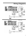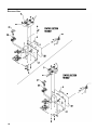
1
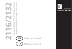
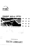
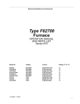
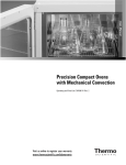
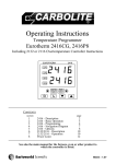
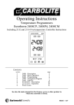
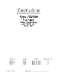
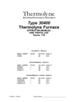
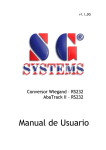
BARNSTEAD|THERMOLYNE CORPORATION
Type FB1300 & FB1400
Furnaces
OPERATION AND REPAIR MANUAL
AND PARTS LIST
SERIES 1256 & 1257
Model Numbers
FB1310M, FB1310M-26, FB1314M, FB1315M, FB1318M,FB1310M-33
FB1410M, FB1410M-26, FB1414M, FB1415M, FB1418M, FB1410M-33
LT1256X1 • 8/27/01
Serial Number
Table of Contents
Safety Information ..............................................................................................................................................3
Important Information....................................................................................................................................3
Warnings ......................................................................................................................................................4
Introduction..........................................................................................................................................................5
Intended Use ................................................................................................................................................5
General Usage..............................................................................................................................................5
Principles of Operation ................................................................................................................................5
General Specifications ........................................................................................................................................6
Declaration of Conformity ............................................................................................................................7
Unpacking ..........................................................................................................................................................8
Installation ..........................................................................................................................................................9
Site Selection................................................................................................................................................9
Electrical Connections..................................................................................................................................9
Operation ..........................................................................................................................................................10
Power Switch..............................................................................................................................................10
Cycle Light..................................................................................................................................................10
Door Safety Switch ....................................................................................................................................10
Single Setpoint Controller ................................................................................................................................10
Basic Operation ..........................................................................................................................................11
Buttons and Indicators................................................................................................................................11
To View or Change the Setpoint ................................................................................................................12
To View the Display Units ..........................................................................................................................12
To View the % Output Power......................................................................................................................12
Controller Parameters ................................................................................................................................12
Alarms ........................................................................................................................................................13
Sensor Break Protection ............................................................................................................................14
Overt Temperature Protection (OTP)..........................................................................................................14
Tuning ........................................................................................................................................................15
Furnace Loading ..............................................................................................................................................16
Preventive Maintenance....................................................................................................................................17
Troubleshooting ................................................................................................................................................18
Maintenance and Servicing ..............................................................................................................................19
To Replace Heating Element......................................................................................................................19
To Replace Thermocouple..........................................................................................................................22
To Replace Insulation ................................................................................................................................24
To Replace Door Switches ........................................................................................................................25
To Replace Solid State Relay ....................................................................................................................26
To Replace PC Board (Controller)..............................................................................................................26
Wiring Diagram..................................................................................................................................................27
Exploded View ................................................................................................................................................28
2
Safety Information
Alert Signals
Warning
Warnings alert you to a
possibility of personal injury.
Caution
Cautions alert you to a
possibility of damage to the
equipment.
Note
Notes alert you to pertinent facts
and conditions.
Hot Surface
Hot surfaces alert you to a
possibility of personal injury if
you come in contact with a
surface during use or for a
period of time after use.
Important Information
This manual contains important operating and
safety information. You must carefully read and
understand the contents of this manual prior to
the use of this equipment.
Your Thermolyne FB1300 Model or FB1400
Model Furnace has been designed with function,
reliability, and safety in mind. It is your responsibility to install it in conformance with local electrical codes. For safe operation, please pay
attention to the alert signals throughout the manual.
Warnings
To avoid electrical shock, this furnace must:
1. Use a properly grounded electrical outlet
of correct voltage and current handling
capacity.
2.
Be disconnected from the power supply
before servicing.
3.
Have the door switch operating properly.
To avoid burns:
1. “Caution: Hot Surface. Avoid Contact.”
Do not touch the exterior or interior surfaces of the furnace during use or for a
period of time after use.
To avoid personal injury:
1. Do not use in the presence of flammable
or combustible materials — fire or explosion may result. This device contains
components which may ignite such
material.
2.
Refer servicing to qualified personnel.
3
SAFETY INFORMATION
Please note the following WARNINGS:
WARNING
This warning is presented for compliance with California Proposition 65 and other regulatory agencies and only applies to the insulation in this product. This product contains refractory ceramic, refractory ceramic fiber or fiberglass insulation, which can produce respirable
dust or fibers during disassembly. Dust or fibers can cause irritation and can aggravate
preexisting respiratory diseases. Refractory ceramic and refractory ceramic fibers (after
reaching 1000°C) contain crystalline silica, which can cause lung damage (silicosis). The
International Agency for Research on Cancer (IARC) has classified refractory ceramic fiber
and fiberglass as possibly carcinogenic (Group 2B), and crystalline silica as carcinogenic to
humans (Group 1).
The insulating materials can be located in the door, the hearth collar, in the chamber of the
product or under the hot plate top. Tests performed by the manufacturer indicate that there
is no risk of exposure to dust or respirable fibers resulting from operation of this product
under normal conditions. However, there may be a risk of exposure to respirable dust or
fibers when repairing or maintaining the insulating materials, or when otherwise disturbing
them in a manner which causes release of dust or fibers. By using proper handling procedures and protective equipment you can work safely with these insulating materials and
minimize any exposure. Refer to the appropriate Material Safety Data Sheets (MSDS) for
information regarding proper handling and recommended protective equipment. For additional MSDS copies, or additional information concerning the handling of refractory ceramic
products, please contact the Customer Service Department at Barnstead|Thermolyne
Corporation at 1-800-553-0039.
4
Introduction
Intended Use
The FB1300 Model and FB1400 Model furnaces are general purpose laboratory and heat
treating furnaces. For optimum element life,
observe the following temperature ranges:
100°C (212°F) to 982°C (1800°F) for continuous
use, or from 982°C (1800°F) to 1100°C
(2012°F) for intermittent use. Continuous use is
operating the furnace for more than three
straight hours, and intermittent use is operating
the furnace for less than three hours.
The unit consists of a heating chamber and a
digital controller. See Figure 1 for the overall
shape and general features of the unit.
General Usage
Do not use this product for anything other than
its intended usage.
Principles of Operation
The furnace chamber is heated by a single
three section resistant heater which is embedded in a refractory material. The chamber is
insulated with a ceramic fiber insulation. The
temperature is controlled by an electronic control. The temperature is measured by a thermocouple and is registered on a digital display. For
safety, door switches are incorporated to
remove power from the heating elements when
the door is opened. The furnace is supported by
the control section which also houses the electrical connections.
5
General Specifications
FB1300 Models
Dimensions: (handle not included)
Chamber: 4” W x 3.75” H x 4.5” D (10.2 x 9.5 x 11.4 cm)
Overall : 7.9” W x 13.8” H x 8.5” D (20.0 x 34.9 x 21.6 cm)
Weight: 15.7 lb. (7.1 kg)
Electrical Ratings:
Model #
Volts
Amps
Watts
Phase
Frequency
FB1310M
220-240
4.4
1060
1
50/60
FB1310M-26
220-240
4.4
1060
1
50/60
FB1310M-33
220-240
4.4
1060
1
50/60
FB1314M
100
10.6
1060
1
50/60
FB1315M
120
8.9
1060
1
50/60
FB1318M
208
5.1
1060
1
50/60
Temperature: Operating Range (continuous): 982°C; (intermittent): 1100°C.
Environmental Conditions:
Operating: 17°C - 27°C; 20% - 80% relative humidity, non-condensing. Installation
Category II (over-voltage) in accordance with IEC 664. Pollution Degree 2 in
accordance with IEC 664. Altitude limit: 2,000 meters.
Storage: -25°C - 65°C; 20% - 80% relative humidity.
FB1400 Models
Dimensions: (handle not included)
Chamber: 5.00” W x 4.25” H x 6.00” D (12.7 x 10.8 x 15.2 cm)
Overall: 9.7” W x 15.8” H x 11.1” D (24.6 x 39.0 x 28.3 cm)
Weight: 23 lb. (10.4 kg)
Electrical Ratings:
Model #
Volts
Amps
Watts
Phase
Frequency
FB1410M
220-240
6.3
1520
1
50/60
FB1410M-26
220-240
6.3
1520
1
50/60
FB1410M-33
220-240
6.3
1520
1
50/60
FB1414M
100
14.5
1520
1
50/60
FB1415M
120
12
1450
1
50/60
FB1418M
208
7.3
1520
1
50/60
Temperature: Operating Range (continuous): 982°C; (intermittent): 1100°C.
Environmental Conditions:
Operating: 17°C - 27°C; 20% - 80% relative humidity, non-condensing. Installation
Category II (over-voltage) in accordance with IEC 664. Pollution Degree 2 in
accordance with IEC 664. Altitude limit: 2,000 meters.
Storage: -25°C - 65°C; 20% - 80% relative humidity.
6
GENERAL SPECIFICATIONS
Declaration of Conformity
Barnstead|Thermolyne hereby declares under its sole
responsibility that this product conforms with the technical requirements of the following standards (-33 models
only):
EMC:
EN 50081-1
Generic Emission Standard;
EN 50082-1
Generic Immunity Standard.
Safety: EN 1010-1-92 Safety requirements for
electrical equipment for
measurement,control and
laboratory use; Part I:
General Requirements
EN 1010-2-010 Part II: Particular requirements
for laboratory equipment for the
heating of materials
per the provisions of the Electromagnetic Compatibility
Directive 89/336/EEC, as amended by 92/31/EEC and
93/68/EEC, and per the provisions of the Low Voltage
Directive 73/23/EEC, as amended by 93/68/EEC.
The authorized representative located within the
European Community is:
Electrothermal Engineering, Ltd.
419 Sutton Road
Southend On Sea
Essex SS2 5PH
United Kingdom
Copies of the Declaration of Conformity are available
upon request.
7
Unpacking
8
1.
Visually check for any physical
damage to the shipping container.
2.
Inspect the equipment surfaces that
are adjacent to any damaged area.
3.
Open the furnace door and remove
the packing material from inside the
furnace chamber.
4.
Vacuum the chamber prior to use to
remove the insulation dust due to
shipment.
5.
Retain the original packaging material if reshipment is foreseen or
required.
Installation
Site Selection
Caution
Install furnace on a sturdy surface and allow
Be sure ambient temperature does adequate space for ventilation.
not exceed 40°C (104°F). The recommended ambient temperature is
17°C - 27°C. Ambients above this
Electrical Connections
level may result in damage to the
The electrical ratings are located on the speccontroller.
ification plate on the back of the furnace.
Consult Barnstead/Thermolyne if your electrical service is different than those listed on the
Caution
specification plate. Be sure the front power
Allow at least six inches of space switch is in the OFF position before connectbetween the furnace and any com- ing the furnace to your electrical supply.
bustible surface. This permits the
heat from the furnace case to
escape so as not to create a possible fire hazard.
Warning
To avoid electrical shock, this furnace must always use a properly
grounded outlet of correct voltage
and current handling capacity.
9
Operation, All Modes
Warning
To avoid personal injury do not use
in the presence of flammable or
combustible chemicals; fire or
explosion may result. This device
contains components which may
ignite such materials.
Hot Surface
Caution: Avoid Contact. To avoid
burns, this furnace must not be
touched on the exterior or interior
surfaces during use or for a period
of time after use.
Power Switch
Both the ON/OFF power switch and the digital
display will illuminate when power is switched
ON. The furnace will begin to heat to the controller's current setpoint. (See the instructions
for your type of controller for information on
checking and setting the setpoint.)
Cycle Light
The amber cycle light will illuminate whenever
the power is being applied to the heating elements. The cycle light will turn on and off as
the furnace reaches the setpoint.
Door Safety Switch
Warning
Always wear safety glasses or a
safety shield and high temperature
gloves when loading or unloading
the furnace. Long sleeved, fire
retardant clothing and a fire retardant apron is also recommended.
Warning
To avoid electrical shock, the door
safety switch must be
operating properly.
10
The door safety switch removes power from
the heating elements when the door is
opened. Open and close the door a few
times; note that the amber CYCLE light will
switch off when the door is opened. If this
condition is not true, consult the
Troubleshooting section before proceeding.
This check must be done when the furnace is
heating and the cycle light is illuminated.
Single Setpoint Controller
Output 1
Output 2
Temperature
Display
The single setpoint model furnace controller
is a single setpoint controller which provides a
single digital display to indicate the current
chamber temperature or setpoint temperature.
This temperature controller features sensor
break protection and self-tuning capability.
Display
Window
Basic Operation
When the controller is turned ON it will perform a short self-test and then display the
measured value (process value) in the HOME
DISPLAY.
PAGE
Button
SCROLL
Button
DOWN ARROW
Button
UP ARROW
Button
Buttons and Indicators
OP1 (Output 1): Illuminates when the logic
output is ON.
OP2 (Output 2): Illuminates when the relay
output is ON (will go out during an alarm situation).
Single Setpoint Models
PAGE button: Allows you to select a new list
of parameters.
Note
If at any time you want to return to
the HOME DISPLAY, simultaneously press the PAGE and
SCROLL buttons.
SCROLL button: Allows you to select a parameter within a list of parameters.
DOWN button: Allows you to decrease a
value.
UP button: Allows you to increase a value.
To View or Change the
Setpoint
To view the setpoint, press and release the
UP or DOWN buttons. If you want to change
the setpoint, continue pressing until the
11
SINGLE SETPOINT
CONTROLLER
desired setpoint value is displayed and then
release the button. A few seconds after the button
is released, the controller will accept the new
value and revert to the HOME DISPLAY.
To View the Display Units
From the HOME DISPLAY press the SCROLL
button. The display will show the temperature
units in °C/F/K and then return to the HOME DISPLAY. (Call Customer Service if you require a different temperature unit.)
To View the % Output Power
From the HOME DISPLAY press the SCROLL
button twice. Press and release the UP or DOWN
button to view the % output power. This value is a
read-only value and cannot be changed.
Controller Parameters
Home display
°C: Temperature units in Celsius. Temperature
units can not be changed without entering the
configuration. Contact Customer Service if a different temperature unit is required.
OP: % output power demand.
IdHi: Deviation high alarm.
Al List
IdHi: Deviation high alarm.
12
SINGLE SETPOINT CONTROLLER
Atun List
tunE: One-shot autotune enable.
Pid List
Pb: Proportional band (in display units).
ti: Integral time in seconds.
td: Derivative time in seconds.
ACCS List Code: Access code (Code needed to enter or change the other configuration
parameters which are not normally accessible.) Not accessable.
Alarms
The controller will flash an alarm message in
the home display if an alarm condition is
detected.
2FSH: Measured value full scale high alarm.
IdHi: Measured value deviation high alarm.
S.br: Sensor break: check that sensor is connected correctly.
Note
The following alarm messages
are factory default settings and
may vary if you have changed
the configuration of your
controller:
L.br: Loop break: check that the heating circuits are working properly.
Ld.F: Heater Circuit fault: indication of either
an open or short solid sate relay, a blown
fuse, missing supply or open circuit heater.
IDHi: = 50°C
2FSH = 1125°C
13
SINGLE SETPOINT CONTROLLER
Sensor Break Protection
This controller provides sensor break protection in
the event the thermocouple opens. If an open thermocouple condition occurs, the digital display will
blink “S.br” and the power to the heating element
will be shut OFF (Cycle light will extinguish).
Over-Temperature Protection
(OTP)
The OTP will be in effect during any alarm condition when the temperature of the furnace has deviated beyond the limit. The “Deviation High” alarm is
the only alarm value which can be changed. To
change it, press the SCROLL button until “IdHi”
appears on the display. Press the UP or DOWN
button to select the OTP value you desire. We recommend a value of 20° above your working temperature to provide protection for your workload.
Tuning
Note
Furnace must be at ambient
temperature before starting a tune.
14
This controller incorporates a self-tuning feature
which determines the optimum control parameters
for the best temperature accuracy with your load
and setpoint. Use this feature the first time you use
your furnace and each time you change either your
setpoint or the type of load you are heating.
Barnstead|Thermolyne recommends you use this
feature to provide the best temperature accuracy
the controller can attain. To use the tuning feature:
1. Adjust the setpoint to your desired value.
2.
Press the PAGE button until display reads,
“Atun.”
SINGLE SETPOINT CONTROLLER
Note
Tune has completed when “tunE”
stops flashing on display.
3.
Press the SCROLL button. Display
will read, “tunE.”
4.
Press the UP or DOWN button to
select, “on.”
5.
Simultaneously press the PAGE and
SCROLL buttons to return to the
HOME DISPLAY. The display will
alternately flash between “tunE” and
the HOME DISPLAY while tuning is in
progress.
6.
The controller will then turn the heating on and off to induce an oscillation.
When the measured value reaches
the required setpoint the first cycle will
end.
7.
Tuning will be complete after two
oscillation cycles and then the tuner
will turn itself off.
8.
Normal control function will resume
after the controller calculates tuning
parameters.
15
Furnace Loading
Caution
Do not overload your furnace
chamber or allow the load to
touch the thermocouple. If the
load is to be heated uniformly, it
should not occupy more than
two-thirds of any dimension of
the chamber. Failure to observe
these cautions could result in
damage to furnace components
and/or load.
16
•
For best results of furnace loading, use
less than two-thirds of any dimension of
the chamber. Maintain a 3/4" clearance
between the load and the sides of the
chamber.
•
If you are heating a number of small
parts, spread them throughout the middle two thirds of the chamber.
•
Keep objects away from thermocouple.
•
Raise your load up off the furnace floor
with small pieces of ceramic or a hearth
plate to promote even heating.
•
Use insulated tongs and mittens when
loading and unloading furnace.
•
Always wear safety glasses.
Preventive Maintenance
Warning
Before using any cleaning or
decontamination method
except those recommended
by Barnstead|Thermolyne,
users should check with
Barnstead|Thermolyne that
the proposed method will not
damage the equipment.
Warning
Disconnect the furnace from
power supply before cleaning.
Warning
Opening the door for an
extended period of time will
cause the painted surfaces
above the door to be discolored or burnt.
Contamination is a major cause of element failure,
therefore, when possible, remove the fume forming
material before heating (e.g., cleaning cutting oil
from tool steel).
The resistance wire is high-grade nickel-chromium.
Some chemicals, notably sulphur, halogens, and
cyanides, attack this wire at high temperatures, so
avoid spilling these chemicals in the furnace or
heating them any hotter than necessary. The
refractory cement helps to protect the wire, but will
not completely immunize it from damage.
All heating elements must be considered expendable, and replacement is expected; however, reasonable care in their use will greatly extend the service they will give. As the manufacturer has no control over the use or care of the elements, no specific service guarantee can be made.
Housekeeping is vital to your electric furnace—
KEEP IT CLEAN! Run your furnace up to 871°C
(1600°F) empty occasionally to burn off the contamination that may exist on the insulation and elements. Run for approximately two hours with the
door slightly open. See warning.
Element life is reduced somewhat by repeated
heating and cooling. If the furnace is to be used
again within a few hours, it is best to keep it at the
operating temperature or at a reduced level such
as 260°C (500°F).
During normal use, the thermocouple in your furnace can become oxidized and cause inaccurate
readings; therefore, we suggest that if you regularly
use your furnace you should change your thermocouple once every six months to assure the accuracy of your controller readings.
Clean by wiping the outside case of the unit with a
damp cloth and mild soap solution.
17
Troubleshooting
Problem
Possible Causes
Corrective Action
The furnace does not heat
(CYCLE light does not illuminate).
No power.
Check power source and fuses or
breakers.
Repair electrical hookup.
Defective electrical hookup.
Thermocouple has oxidized and
opened the circuit. (Open thermocouple
is indicated on the display as a
temperature of 0-5 degrees).
Replace thermocouple.
Fuse(s) blown
Replace fuse(s).
Controller malfunction.
Replace controller.
Door switches malfunction.
Re-align or replace door safety switches.
Defective solid state relay.
Replace output relay.
Power is not cut to heating elements
when the door is open.
Door switches are not functioning
Re-align or replace door switches.
Slow heatup.
Low line voltage.
Install line of sufficient size and proper
voltage. (Isolate furnace from other
electrical loads.)
Heavy load in chamber.
Lighten load in chamber.
Wrong heating element.
Install proper element.
Overheating furnace.
Keep furnace under maximum
temperature.
Heating harmful materials.
Enclose material in container. Clean up
spills in and on chamber. Ventilate
chamber by opening door slightly when
heating known harmful reagents.
Contamination present from
pervious burnout.
Replace insulation material.
Oxidized or contaminated
thermocouple.
Replace thermocouple.
Poor thermocouple connection.
Tighten connections.
Improper loading procedures.
Use proper loading procedures.
Poor ventilation of base.
Clear area around furnace base.
Thermocouple connections
reversed. (Indicated by
downscaling of temperature on
display.)
Reconnect thermocouple correctly.
Controller malfunction.
Replace controller.
Repeated element burnout.
Inaccurate temperature
readout.
18
Maintenance and Servicing
Warning
Disconnect the furnace from the
power supply before servicing.
Refer servicing to qualified
personnel.
Note
Perform only maintenance
described in this manual.
Contact an authorized dealer or
our factory for parts and
assistance.
Note
It is seldom necessary to disconnect the thermocouple from
the controller if the thermocouple is in good condition.
To Replace Heating Element
1.
Set the furnace on its top. (See Figure 3).
Remove thermocouple cover. (If
equipped.)
2.
Remove screw and clamp holding thermocouple, then grasp the thermocouple
at the bend where it enters the furnace
chamber and pull straight back. Retain
porcelain insulator.
3.
When the thermocouple tip is clear of the
furnace back, bend it out of the way.
4.
Remove the screws holding the steel
back plate to the case.
5.
Remove the steel back plate.
Thermocouple cover
Porcelin
insulation
Step 1(if equipped)
Step 3
Step 2
Heating element
with rough side up
Bend up
Straight edge
(or board)
Step 4
Step 5
Step 6
Figure 3: Replacement of a Heating Element
19
MAINTENANCE AND SERVICING
Note
The hearth plate contains no
heating coil, and may be saved
for re-installation if it is in good
condition. The hearth plate is
replaceable independent of the
heating element.
6.
Remove the back insulation block by opening the door and gently pushing it out.
Support this insulation block while removing
it, as it is quite soft and easily crumbled at
the edges.
7.
Remove bottom cover to obtain access to
terminals.
These steps will expose the heating element leads
and insulating bushings in the bottom plate of the
furnace.
8. Cut the element leads between the element
and the terminal block. (There are two
leads.) The element and hearth plate unit
may now be removed by pushing it straight
back out of the furnace. Use care not to
damage the chamber insulation when
removing the hearth plate and element as it
can be reused if it has not been contaminated.
9.
Remove the old element lead wire and
power wires from the terminal block, and
save the sleeving for re-installation on the
new element leads. Sleeving must be
replaced if cracked or brittle!
10. New elements are shipped flat to protect
them from damage in shipment, and to save
space in storage. They must be formed
before installation.
11. Place the element on a flat surface with the
rough side up. Place a board or other
straight edge along one row of notches.
12. Gently bend the element along the straight
edge. The refractory cement will break
along the row of notches.
20
MAINTENANCE AND SERVICING
Make the bend 90°, avoiding excessive bending. (The element wires will be exposed at the
corner thus formed. This will not affect its life
or performance.)
13. Bend the other side of the element.
14. Place the hearth plate across the open end of
the ‘’U” shaped element.
Note
Nicking or damaging the element leads will cause premature element failure.
15. Slide the element and hearth plate unit into
the chamber, pushing it firmly against the
hearth collar. Use care not to damage the soft
insulation. Remove any crumbs of insulation
that may get between the unit and the hearth
collar.
16. Thread the element leads through the ceramic bushings. Bend the leads so they lie close
to the refractory plate and the bottom insulation block. (The easiest and safest way to do
this is to press the wire flat with a stick or
blunt pusher. Do not use a sharp object or
nick the wire.)
17. Replace the sleeving and bend the lead 3/4
turn around the terminal screw. Cut off the
excess wire. Replace power wires on top of
element lead wires and tighten screw. Do not
cross the wire over itself around the terminal;
this makes it difficult to keep the connection
tight and prevents good electrical contact. If
you have excess wire, cut it off. Make sure
element lead wires are not touching any other
wires.
18. Replace the back insulation block and back
plate.
19. Examine the thermocouple, and, if it is good,
reinsert it into the chamber. It should extend
21
MAINTENANCE AND SERVICING
about 1-1/2" into the chamber. Make sure
porcelain insulator is in place for the thermocouple to pass through on the steel
back plate. Replace clamp and screw.
(Excessive scaling, pitting, or cracks are
some indications that the thermocouple
may need to be replaced.)
20. Replace bottom cover of control unit.
21. Replace thermocouple cover.
22. If replacement of back insulation is necessary, carefully redrill hole for thermocouple, using back cover as guide.
23. Reconnect furnace to power supply.
24. Test operation of furnace.
To Replace Thermocouple
Warning
Disconnect the furnace from the
power supply before servicing.
Note
If the thermocouple touches metal,
this could short out the signal,
causing the control to display room
temperature. This could cause the
furnace temperature to run away,
possibly damaging furnace components.
22
1.
Set furnace on its top.
2.
Remove thermocouple cover. (If equipped.)
3.
Remove screw and clamp holding the thermocouple, then grasp the thermocouple at
the bend where it enters the chamber and
pull it straight back from the furnace. Retain
porcelain insulator.
4.
Remove bottom cover.
5.
Disconnect the thermocouple from the terminal block by removing the screws on the
terminals. Pull the thermocouple through
the hole in the furnace base and discard.
6.
Insert the new thermocouple into the back
of the furnace chamber. Make sure the
porcelain insulator extends through the
steel back plate to prevent the lead wires
from touching metal.
MAINTENANCE AND SERVICING
Note
If the control temperature display
moves downward, the thermocouple leads are reversed.
7.
Thread the thermocouple through the hole
in the base which has a nylon insulator,
replace clamp and screw.
8.
Bend the thermocouple sharply toward terminal block.
9.
Secure the two yellow wires marked “+”
together on the terminal block. Secure the
two red wires “-” together on the adjacent
terminal. Make sure connections are secure
to terminal block.
A polarity test of the thermocouple and lead wire is
easily made with the use of a magnet. On chromel
alumel thermocouples and lead wire, the non-magnetic wire is positive ( + ) and the magnetic wire is
negative ( - ).
10. Replace bottom plate.
11. Replace thermocouple cover. (If equipped.)
12. Reconnect furnace to power supply.
13. Test operation of furnace.
To Replace Insulation
Warning
Disconnect furnace from power
supply before servicing.
1.
Remove thermocouple cover. (If equipped.)
2.
Set furnace on its top and remove screw
and clamp securing thermocouple, then
grasp thermocouple and remove by pulling
it straight back. Retain porcelain insulator.
3.
Remove back plate.
4.
Remove bottom cover.
5.
Disconnect the element leads from terminal
block.
23
MAINTENANCE AND SERVICING
6. Disconnect thermocouple leads from terminal
block.
Note
Identify or mark wires disconnected to ensure proper placement and connection when reinstalling.
7.
Remove four nuts holding control section to
furnace chamber.
8.
Remove the ground nut.
9.
Remove the control section from the furnace
chamber. Remove plates, screws, spacers
and nuts. Be sure to note how plates are
assembled together for reassembly.
10. Remove back piece of insulation by opening
door and pushing it out gently.
11. Remove bottom piece of insulation by lifting it
out.
12. Remove element and hearth plate by pulling
it straight back out of the furnace chamber.
(Be careful not to damage elements.)
13. Remove side insulating pieces.
14. To remove top insulating piece and hearth
collar, position the furnace on its side.
Remove both objects from furnace.
15. Reposition furnace on its top. Reinsert new
hearth collar and the new top piece of insulation. Insert the new side pieces of insulation last.
16. Reinsert element and hearth plate unit into
the chamber, pushing it firmly against the
hearth collar. (Be careful not to damage
insulation.)
17. Reinsert new bottom piece of insulation over
hearth plate. (Element leads and ceramic
bushings should be exposed above insulation bottom piece.)
24
MAINTENANCE AND SERVICING
18. Thread the element leads and ceramic
bushings through the bottom plate. Bend
the leads so they lie close to the refractory
plate and the bottom insulation block. (The
easiest and safest way to do this is to press
the wire flat with a stick or blunt pusher. Do
not use a sharp object or nick the wire.)
Secure plate to furnace chamber.
19. Reverse steps 1-9 to reassemble furnace.
To Replace Door Switches
Warning
Disconnect furnace from power
supply before servicing.
1.
Place furnace upside down and remove bottom cover.
2.
Disconnect wires from door switches. Identify
or mark wires disconnected from door switches to ensure proper placement and connection when reinstalling.
3.
Remove two screws and nuts from door
switches and slide door switches out.
4.
Install new door switches to bracket. Place
furnace in an upright position. Adjust door
switches until a click is heard from the
switches, when furnace door is approximately 2" from being completely closed. Secure
door switches to bracket.
5.
Place furnace upside down. Reconnect the
wires to new door switches.
6.
Replace bottom cover and place furnace
upright.
7.
Reconnect furnace to power supply.
8.
Test operation of door switches as
described in step 4.
25
MAINTENANCE AND SERVICING
Warning
Disconnect furnace from power
supply before servicing.
Warning
Disconnect furnace from power
supply before servicing.
26
To Replace Solid State Relay
1.
Place furnace upside down and remove the
bottom cover.
2.
Disconnect the wires from the solid state
relay. Identify or mark the wires disconnected to ensure proper placement and connection when re-installing.
3.
Remove solid state relay from bottom cover.
Note placement of solid state relay.
4.
Install new solid state relay and reconnect
wires.
5.
Replace bottom cover and place furnace
upright.
6.
Reconnect furnace to power supply.
To Replace Controller
1.
Place furnace upside down and remove
bottom cover.
2.
Disconnect wires from the controller.
Identify or mark wires disconnected to
ensure proper placement and connection
when re-installing.
3.
Remove the controller from bottom cover.
4.
Install new controller and secure.
5.
Reconnect wires identified in step 3 to new
controller.
6.
Replace bottom cover and place furnace
upright.
7.
Reconnect furnace to power supply.
Wiring Diagrams
FB 1400 models
FB1300 models
27
EXPLODED VIEW
28
EXPLODED VIEW
29
Replacement Parts List
Quantity
Key#
1
1
1
1
1
1
1
1
2
2
3
4
5
5
6
6
7
7
8
8
9
9
10
10
11
11
12
13
14
14
15
15
16
17
18
18
19
20
21
21
21
22
22
30
Description
Required
Heating element (100V - FB1314M)
1
Heating element (120V - FB1315M)
1
Heating element (208V - FB1318M)
1
Heating element (240V - FB1310M, -33)
1
Heating element (100V - FB1414M)
1
Heating element (120V - FB1415M)
1
Heating element (208V - FB1418M)
1
Heating element (208V - FB1410M, -33)
1
Thermocouple (FB1300 models)
1
Thermocouple (FB1400 models)
1
Solid State Relay (all models)
1
Door Switches (all models)
2
Control (FB1300M & FB1400M models except FB1410M-33) 1
Control (FB1400M-33 model only)
1
Insulation Btm (all FB1300 models)
1
Insulation Btm (all FB1400 models)
1
Insulation Back (all FB1300 models)
1
Insulation Back (all FB1400 models)
1
Insulation Top (all FB1300)
1
Insulation Top (all FB1400)
1
Insulation Hearth Collar (FB1300)
1
Insulation Hearth Collar (FB1400)
1
Insulation Sides (FB1300)
2
Insulation Sides (FB1400)
2
Cycle Light (amber) (all 100V & 120V)
1
Cycle Light (amber) (all 208V & 240V)
1
Terminal Block
1
Terminal Block
1
Power Switch (100 & 120V models)
1
Power Switch (208 & 240V models)
1
Door Assembly (FB1300 all models)
1
Door Assembly (FB1400 all models)
1
Element Sleeving (all models)
1
Element Sleeving (all FB1300 models)
1
Hearth Plate (all FB1300 models)
1
Hearth Plate (all FB1400 models)
1
Filter (all -33 models)
1
Fuse Holder (all models)
1
Fuse 10 amp .25 x 1.25 - (Buss™ Type ABC,
2
240V & 208V models)
Fuse 15 amp .25 x 1.25 (Buss™ Type ABC,
2
120V models)
Fuse 20 amp .25 x 1.25 (Buss™ Type ABC,
2
100V models)
Dial Plate Label (FB1300)
1
Dial Plate Label (FB1400)
1
Part Number
EL140X2
EL44X1
EL44X3
EL44X2
EL186X2
EL48X1
EL48X3
EL48X2
TC1256X1
TC746X1A
RYX34
SWX163
CN71X81
CN71X101
JC44X1
JC48X2
JC44X4
JC48X1
JC44X3
JC48X3
HC44X1
HC48X1
JC460X2
JC48X4
PLX76
PLX82
TRX136
TRX96
SWX143
SWX144
DR347X1A
DR348X1A
SL745X1
SL59X2
PH44X1
PH48X1
CAX98
FZX26
FZX30
2-58147
FZX29
DLX248
DLX249
31
One Year Limited Warranty
BARNSTEAD|THERMOLYNE CORPORATION (“BARNSTEAD”) warrants that if a product manufactured by
Barnstead shall be free of defects in materials and workmanship for one (1) year from the first to occur of (i)
the date the product is sold by BARNSTEAD or (ii) the date the product is purchased by the original retail customer (the “Commencement Date”). Except as expressly stated above, BARNSTEAD MAKES NO OTHER
WARRANTY, EXPRESSED OR IMPLIED, WITH RESPECT TO THE PRODUCTS AND EXPRESSLY DISCLAIMS ANY AND ALL WARRANTIES, INCLUDING BUT NOT LIMITED TO, WARRANTIES OF DESIGN,
MERCHANT ABILITY AND FITNESS FOR A PARTICULAR PURPOSE.
An authorized representative of BARNSTEAD must perform all warranty inspections. In the event of a defect
covered by BARNSTEAD’s warranty, BARNSTEAD shall, as its sole obligation and exclusive remedy, provide
free replacement parts to remedy the defective product. In addition, for products sold by BARNSTEAD within
the continental United States or Canada, BARNSTEAD shall provide provide free labor to repair the products
with the replacement parts, but only for a period of ninety (90) days from the Commencement Date.
BARNSTEAD’s warranty provided hereunder shall be null and void and without further force or effect if there
is any (i) repair made to the product by a party other than BARNSTEAD or its duly authorized service representative, (ii) misuse (including use inconsistent with written operating instructions for the product), mishandling, contamination, overheating, modification or alteration of the product by any customer or third party or
(iii) use of replacement parts that are obtained from a party who is not an authorized dealer of BARNSTEAD.
Heating elements, because of their susceptibility to overheating and contamination, must be returned to the
BARNSTEAD factory and if, upon inspection, it is concluded that failure is due to factors other than excessive
high temperature or contamination, BARNSTEAD will provide warranty replacement. As a condition to the
return of any product, or any constituent part thereof, to BARNSTEAD’s factory, it shall be sent prepaid and a
prior written authorization from BARNSTEAD assigning a Return Goods Number to the product or part shall
be obtained.
IN NO EVENT SHALL BARNSTEAD BE LIABLE TO ANY PARTY FOR ANY DIRECT, INDIRECT, SPECIAL,
INCIDENTAL, OR CONSEQUENTIAL DAMAGES, OR FOR ANY DAMAGES RESULTING FROM LOSS OF
USE OR PROFITS, ANTICIPATED OR OTHERWISE, ARISING OUT OF OR IN CONNECTION WITH THE
SALE, USE OR PERFORMANCE OF ANY PRODUCTS, WHETHER SUCH CLAIM IS BASED ON CONTRACT, TORT (INCLUDING NEGLIGENCE), ANY THEORY OF STRICT LIABILITY OR REGULATORY
ACTION.
32