1
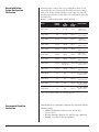
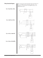
Installation,Operation
and Maintenance Manual
PN 750-0100-001
JSP JSP J
JSP JSP JSP
™
®
JSP™ Installation, Operation and Maintenance Manual
Surge
Protective
Devices
Table of Contents
Installation Assistance
3
Importance of Correct Installation
3
Warnings
3
Before Installation
4
System Configuration Verification
4
Environmental Condition Verification
4
Wiring Connection Diagram
5-6
Single Phase 2-Wire
5
Split-Phase, 3-Wire
5
3-Phase, 4-Wire WYE
5
3-Phase, 3-Wire DELTA
5
3-Phase, 4-Wire High-Leg DELTA
6
Conductor Routing
6
Upstream Over-Current Protection Device
6
Conductor Sizing
7
Mounting
7
Conduit Openings and Enclosure / Mounting Dimensions
2
7-8
Electrical Connections
8
Connecting Form C Dry Contacts
9
Verification and Power Up
10
Troubleshooting
11
Technical Assistance
11
Return and Warranty Procedures
11
Warranty Statement
12
JSP™ Installation, Operation and Maintenance Manual
Installation Assistance
Thank you for choosing the Joslyn® JSP™ series Surge Protective
Device (SPD). We look forward to fulfilling your facility-wide
surge protection needs.
Monday through Friday, 8:00 a.m. to 5:00 p.m. (EST) at
800.238.5000.
The Importance of
Correct Installation
This manual provides guidelines for the proper installation of the
JSP family of devices. Proper product selection and compliance
with these guidelines will help your new suppression system
provide years of reliable service. If installers are unsure about the
facility electrical configuration or have other installation-related
questions, it is recommended they consult with a master electrician or other qualified electrical professional.
When shortcuts are taken or installation procedures are not followed, the JSP system may be damaged or may not provide adequate protection. It is extremely important to follow these installation procedures carefully.
WARNINGS!
!
!
WARNING! The JSP™ warranty is voided if the unit is damaged as a result of improper installation or the installer’s failure to verify the following conditions prior to installation.
WARNING! HAZARDOUS VOLTAGES PRESENT Improper
installation or misapplication may result in serious personnel injury/or damage to the electrical system. Read the complete installation instructions before proceeding with installation. Remove all power to the electrical panel before
installing or servicing the surge protective device (SPD).
IMPORTANT SAFETY INSTRUCTIONS All work must be performed by licensed and qualified personnel. The electrical system
must be properly grounded in accordance with the U.S. National
Electrical Code, state and local codes or other applicable codes for
this SPD to function properly. This device is suitable for installation
where the available short circuit current is 200,000 rms symmetrical
amperes up to 600VAC or less. For countries outside of the US follow
applicable electrical specifications for the electrical specifications for
the country the unit is being used in.
!
JSP™ Installation, Operation and Maintenance Manual
This Statement is only applicable for TNCS grounded systems.
WARNING! Check to ensure that a proper bond is installed
between neutral and ground at the transformer upstream
from all 3-phase WYE, 3-phase high leg DELTA or split-phase
JSP device (See NEC Article 250). If the transformer is not
accessible, check the main service disconnect/panel for the NG bond. Lack of a proper bond will damage JSP and void the
warranty.
3
Before Installation:
System Configuration
Verification
Confirm that the voltage(s) and service configuration shown on the
JSP product label are consistent with the voltage and service configuration of the facility. A model number is on the right side of the JSP
unit. Each model number corresponds to the configurations printed in
the table below:
Example of a SPD model number: JSP160-3Y208-F
MODEL
NOMINAL
VOLTAGE
L-N
VOLTAGE
RANGE
L-L
VOLTAGE
RANGE
CONFIGURATION
JSPxxx-1P120*
120
90-132
90-132
Single Phase
2-wire+ground
JSPxxx-1P240*
240
180-264
180-264
Single Phase
2-wire+ground
JSPxxx-1S240*
120/240
90-132
180-280
Split-Phase
3-wire+ground
JSPxxx-3Y208*
120/208
312-382
540-660
Three-Phase
4-wire+ground
JSPxxx-3Y380*
220/380
198-253
342-440
Three-Phase
4-wire+ground
JSPxxx-3Y415*
240/415
216-264
373-457
Three-Phase
4-wire+ground
JSPxxx-3Y480*
277/480
249/305
432-528
Three-Phase
4-wire+ground
JSPxxx-3H240*
120/240
108-132(A, C)
187-229 (B)
JSPxxx-3Y600
347/600
313-394
540-660
Three-Phase WYE
4-wire+ground
JSPxxx-3D240*
240
N/A
216-264
Three-Phase DELTA
3-wire+ground
JSPxxx-3D380
380
N/A
342-418
Three-Phase DELTA
3-wire+ground
JSPxxx-3D480
480
N/A
432-528
Three-Phase DELTA
3-wire+ground
JSPxxx-3D600
600
N/A
540-660
Three-Phase DELTA
3-wire+ground
216-264 Three-Phase High-Leg
4-wire+ground
xxx denotes surge rating per phase (60, 80, 100, 120, 160, 200, 240, 300, 400)
* These are the only voltages available on the 60, 80, and 100kA systems
Environmental Condition
Verification
4
Confirm that the environmental conditions are consistent with the
following ranges:
• Ambient Temperatures: Between -40° and +158°F
(-4.5 to 70º C).
• Relative Humidity: Between 5% and 95% non-condensing.
• Altitude: Less than 13,000 feet (4000m).
JSP™ Installation, Operation and Maintenance Manual
Wiring Connection Diagrams
Figures 1-4 show the electrical relationship between JSP and these five
basic service TNCS grounded configurations: Single phase, 2-wire;
Split-phase, 3-wire; Three-phase, 4-wire WYE; Three-phase, 3-wire
DELTA and Three-phase,
Fig. 1: Single Phase, 2-Wire
TVSS
Fig. 2: Split-Phase, 3-Wire
TVSS
Fig. 3: 3-Phase, 4-Wire WYE
Fig. 4: 3-Phase, 3-Wire DELTA
TVSS
TVSS
JSP™ Installation, Operation and Maintenance Manual
5
Fig.5: 3-Phase, 4-Wire High-Leg DELTA
TVSS
Conductor Routing
!
CAUTION: JSP’s performance will be limited severely if the
conductors are (a) too long, (b) are of too small a wire gauge,
(c) have too many bends or (d) have sharp bends. For optimum performance never exceed 10’.
The factors listed above should be addressed during the design of an
installation to reserve a suitable place for JSP next to its point of connection to the electrical system. The selected mounting location
should allow for the shortest possible conductor runs and a direct
route with a minimum of bends. If bends are required, they should be
sweeping bends (12” radius). Do not make sharp 90° bends for appearance purposes because they will severely decrease the effectiveness of
JSP.
Binding or twisting conductors together using tie-wraps or electrical
tape increases the protection performance of the device.
Upstream Over-Current
Protection Device
The JSP has been listed to UL1449 as a Type 1 SPD. Type 1 SPDs can
be used in Type 1 or Type 2 SPD applications, which means that the
JSP does not need to be connected behind an upstream over current
protection device and can be connected on either the line or load side
of the main service disconnect. The JSP must be connnected in parallel with the electrical system. All JSP units come standard with component-level over-current fusing rated at 200,000 rms symmetrical
amperes at 600VAC and can be connected directly to the electrical
distribution system bus without an upstream over-current protection
device (OCPD). If installing as a Type 2 SPD the use of an external
OCPD is recommended.
If the SPD is connected to a dedicated OCPD, a 60A breaker is
recommended (30A minimum, 200A maximum). The advantage of
using a dedicated over-current device for the SPD (even if the upstream
breaker is 200A or less) is that it allows the SPD to be de-energized
during service without disturbing the electrical service to the rest of
the facility.
6
JSP™ Installation, Operation and Maintenance Manual
Conductor Sizing
Joslyn recommends installing JSP by using the following conductor
size for phase, ground and neutral connections. The conductor length
should be as short as possible to ensure the maximum level of protection. Use a larger conductor (not to exceed the maximum allowed per
a given model) where space and bending radii permit.
Example of a SPD model number: JSP160-3Y208-FB
PRODUCT
LABEL
DESIGNATION
SURGE
CURRENT
CAPABILITY
JSP60
60kA/phase1
#10AWG
#10AWG
#10AWG
JSP80
80kA/phase1
#10AWG
#10AWG
#10AWG
JSP100
100kA/phase1
#10AWG
#10AWG
#10AWG
JSP120
120kA/phase1
#10AWG
#3AWG
#10AWG
JSP160
160kA/phase
#10AWG
#3AWG
#10AWG
JSP200
200kA/phase2
#3AWG
#3AWG
#10AWG
JSP240
240kA/phase2
#3AWG
#3AWG
#10AWG
JSP300
300kA/phase2
#3AWG
#3AWG
#10AWG
CONDUCTOR SIZE
RECOMMENDED MAXIMUM
MINIMUM
1
JSP400
400kA/phase
#3AWG
#3AWG
#10AWG
60through 100kA units are shipped with #10AWG leads. Leads should be shortened
during installation in order to minimize conductor length.
120 through 400kA units are shipped with compression box lugs.
2
1
2
Mounting
Mount the JSP to the building structure using construction methods
and hardware appropriate for your site. Install the conduit and pull
the conductors as specified above or according to the engineer’s
design.
Conduit Openings
If desired, punch holes at this time for the conduit or nipple or
wait until the JSP is mounted to the building structure. Punch holes
only in the designated areas as shown in the following illustration.
!
CAUTION: Careful consideration must be made when selecting an area for conduit entry. There are several components
inside the enclosure that may interfere with the conduit
entry path, therefore, ensure the path is clear of all objects
before drilling. Damages caused by installation errors are
not covered under the product warranty.
See Fig. 5 for conduit openings and enclosure dimensions.
JSP™ Installation, Operation and Maintenance Manual
7
Fig. 5:
Conduit Openings and
Enclosure/Mounting
Dimensions
(W1)
2"0
3. .8mm)
(D)
(W2)
3
(8
3"6
1.4.5mm)
ø0.31
(3
(7.87)
(H1)
A
(H2)
(H3)
(W1)
2"0
3.3.8mm)
(D)
3"6
1.4.5mm)
(W2)
(8
ø0.31
(3
(7.87)
C
ALLOWA BLEAREA FOR COND UITENTRY
(H1)
(H2)
(H3)
B
ALLOWA BLEAREA FOR COND UITENTRY
A
B
C
Dim
JSP60, 80, 100
JSP120, 160
JSP200, 240, 300, 400
H1
6.00
(152.4)
10.00
(254.0)
14.00
(355.6)
H2
6.75
(171.5)
10.75
(273.1)
14.75
(374.7)
H3
7.50
(190.5)
11.50
(292.1)
15.50
(393.7)
W1
6.00
(152.4)
8.00
(203.2)
12.00
(304.8)
W2
4.00
(101.6)
6.00
(152.4)
10.00
(254.0)
D
4.16
(105.7)
6.20
(157.5)
6.20
(157.5)
Weight
12.0
(5.4)
27.0
(12.2)
40.0
(18.2)
All measurements in inches (mm) and pounds (kg)
Electrical Connections
!
CAUTION: Prior to installation ensure the system configuration and voltage is equivalent to the JSP unit being
installed.
Following all applicable National Electrical Code standards as well as
state and local codes, connect phase, neutral* and ground to JSP. The
60kA, 80kA and 100kA units come with 36 inches of #10 AWG conductors. Each phase conductor is labeled (Phase A, B or C). The 120kA,
160kA, 200kA, 240kA, 300kA and 400kA units come with compression
box lugs. The installer must provide the appropiate conductors.
Ensure that the conductor lengths are kept as short and straight as
possible. On all high-leg delta systems, the high-leg (208V L-N) must
be connected to the Phase B of the SPD. (color-coded orange according to NEC).
* The 3-wire plus ground Delta JSP does not have a neutral conductor.
8
JSP™ Installation, Operation and Maintenance Manual
Connecting Form C
Dry Contacts
All JSP units (option -M for 60kA, 80ka, and 100kA) come standard
with one set of Form "C" dry relay contacts for the surge protective
device status. These contacts are for connection to a user-provided
remote alarm and monitoring circuit. The relay contacts are rated
150VDC/125VAC with maximum switching power of 30WDC/60VA AC.
See Figure 6 for the form C contact configuration and terminal location on the monitor board. The annotations on the diagram match the
markings on the terminal block.
When input power is present on all phases, terminals “NO” and “COM”
are an open circuit and terminals “NC” and “COM” are a closed circuit.
The contacts change state when the unit has encountered failure to
one or more phases.
The installer must provide the appropriate raceway and wiring for the
monitoring circuit, observing the restrictions and conduit openings
illustrated in an earlier section of this manual. The installer must
route the monitoring conductors to the terminal blocks on the doormounted main monitoring board. Route the wires to allow the door
to be opened and closed properly. Tighten screws on terminals to
3.5 in-lbs (0.4 Nm). This terminal block will accept wire sizes #28AWG
to #16AWG. #18 – #20 AWG is recommended.
Fig. 6 Remote Monitoring
Terminal Block
Contacts shown in energized normal state
(no fault condition).
COVER EAR VIEW
JSP™ Installation, Operation and Maintenance Manual
9
Verification and Power Up
!
Fig. 7 JSP Diagnostics
WARNING: It is recommended that the cover of the JSP
unit along with its associated cabling be installed prior to
applying power. The monitoring harness, which exits the
epoxy and connects to J2 on the monitor board, contains
line voltage when power is applied to the unit.
Apply power to JSP by closing the over-current protection device or
switch feeding the suppressor.
For Compact JSP Units (60, 80, and 100kA units)
Verify that all “Protection Available” indicating lights are illuminated.
The “Protection Available” indicating light extingush only upon
failure of one or more phases (indicating an alarm condition).
R
For Standard JSP Units (120, 160, 200, 240, 300, and 400) or
-M (60, 80 and 100kA)
Verify that all “Protection Available” indicating lights are illuminated.
The “Protection Available” lights extingush only upon failure of one or
more phases (indicating an alarm condition).
Audible alarm should not operate under normal conditions. The audible alarm can be “muted” by pressing the “ALARM SILENCE” button,
which subsequently will illuminate the “ALARM SILENCED” light.
Pressing the “ALARM SILENCE” button again will enable the audible
alarm.
R
CAUTION: Pressing the “ALARM SILENCE” button when the alarm
has not triggered will prevent the audible alarm from sounding during
a failure.
Fig. 8 JSP with Counter Option
Diagnostics
For JSP Units with surge counter option
(Not available on 60, 80 and 100kA)
The number of surges detected by the SPD is displayed on an eightdigit LCD display on the front of the JSP door. The LCD counter is
battery backed to maintain the number of surges even during a power
loss. Press the reset button on the counter to reset the surge count.
R
10
JSP™ Installation, Operation and Maintenance Manual
Troubleshooting
Your JSP system does not require scheduled maintenance. The unit’s heavyduty construction is designed to provide years of uninterrupted service. The
unit contains no serviceable parts.
INDICATION
One or more phase protection status indicating
lights are off, service required indicating light
is on, or form C alarm contacts have changed
state
PROCEDURE
Verify that the input power feeding
JSP is energized using a voltage tester. If
power is present, contact factory for assistance: 800-238-5000
Technical Assistance
Our staff is ready to support you and answer any questions.
Monday through Friday, 8:00 a.m. to 5:00 p.m. (EST) at 800-238-5000
Returns and Warranty
Procedures
JSP units are warranted for a period of 10 years from date of purchase. In
the event that any module or subassembly within the SPD fails to perform
as specified during the warranty period, call our Technical Support at
800-238-5000.
A Return Material Authorization (RMA) number must be obtained from the
company’s Customer Service department before replacement products can be
shipped. Go to www.joslynsurge.com to complete an online return material
authorization request form. We will immediately ship a replacement for the
defective parts free of charge (installation labor and site preparation excluded). Return the defective parts to Joslyn within 30 days of receiving the
replacement. Failure to return the defective parts will result in billing for the
replacement parts. To help expedite the return procedures, please have the
following information at hand when you contact Joslyn:
INFORMATION
JSP™ Installation, Operation and Maintenance Manual
EXAMPLE
Model Number
JSP120-277/480-3GY
Serial Number
15478-0105-001
Date of Purchase
January 2, 2005 (1st week)
Description of Failure
“Service Required” indicating light
illuminated
Desired Action from Joslyn
Replace
11
Warranty Statement
Joslyn warrants that your Joslyn surge protective device (the
"Product"), shall meet applicable industry standards and specifications
and be free from defects in materials and/or workmanship. Should
any failure of the Product to conform to this warranty appear within
the standard warranty period, Joslyn shall either repair or replace the
defective Product, or part thereof, upon return to Joslyn manufacturing facility in Richmond, Virginia with transportation charges prepaid.
The applicable warranty period as outlined herein.
Joslyn shall have no liability under this warranty for any problems
or defects directly or indirectly caused by misuse of the Product,
alteration of the Product (including removal of any warning labels),
accidents, or improper installation, application, operation, or repair of
the Product.
THIS WARRANTY REPRESENTS THE ENTIRE WARRANTY OF
JOSLYN. ALL OTHER WARRANTIES, EXPRESS OR IMPLIED, ORAL
OR WRITTEN, INCLUDING, BUT NOT LIMITED TO, THE
WARRANTIES OF MERCHANTABILITY AND FITNESS FOR A
PARTICULAR PURPOSE ARE HEREBY DISCLAIMED.
The liability of Joslyn under this warranty is expressly limited to the
replacement or repair of the defective part thereof, at Joslyn sole
option.
IN NO EVENT SHALL JOSLYN BE LIABLE FOR SPECIAL,
INCIDENTAL, OR CONSEQUENTIAL DAMAGES OF ANY KIND OR
CHARACTER, NOR SHALL JOSLYN’ LIABILTY EVER EXCEED THE
PURCHASE PRICE PAID FOR SUCH DEFECTIVE PRODUCT.
This warranty is not transferable and may only be enforced by the sole
purchaser. Claims under this warranty must be submitted to Joslyn
within thirty (30) days of discovery of any Joslyn product defect.
®
©2009 Joslyn and JSP™.
12
Joslyn
5900 Eastport Boulevard
Richmond, VA 23231-4453
Tel: 804.236.3300
800.238.5000
Printed in U.S.A. All Rights Reserved. PN 750-0100-001
JSP™ Installation, Operation and Maintenance Manual