1
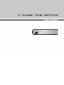
One-Channel Video Receiver WARNING RISK OF ELECTRIC SHOCK DO NOT OPEN WARNING: TO REDUCE THE RISK OF ELECTRIC SHOCK, DO NOT REMOVE COVER (OR BACK). NO USER-SERVICEABLE PARTS INSIDE. REFER SERVICING TO QUALIFIED SERVICE PERSONNEL. COMPLIANCE NOTICE OF FCC: THIS EQUIPMENT HAS BEEN TESTED AND FOUND TO COMPLY WITH THE LIMITS FOR A CLASS A DIGITAL DEVICE, PURSUANT TO PART 15 OF THE FCC RULES. THESE LIMITS ARE DESIGNED TO PROVIDE REASONABLE PROTECTION AGAINST HARMFUL INTERFERENCE WHEN THE EQUIPMENT IS OPERATED IN A COMMERCIAL ENVIRONMENT. THIS EQUIPMENT GENERATES, USES, AND CAN RADIATE RADIO FREQUENCY ENERGY AND IF NOT INSTALLED AND USED IN ACCORDANCE WITH THE INSTRUCTION MANUAL, MAY CAUSE HARMFUL INTERFERENCE TO RADIO COMMUNICATIONS. OPERATION OF THIS EQUIPMENT IN A RESIDENTIAL AREA IS LIKELY TO CAUSE HARMFUL INTERFERENCE, IN WHICH CASE USERS WILL BE REQUIRED TO CORRECT THE INTERFERENCE AT THEIR OWN EXPENSE. WARNING: CHANGES OR MODIFICATIONS NOT EXPRESSLY APPROVED BY THE PARTY RESPONSIBLE FOR COMPLIANCE COULD VOID THE USER’S AUTHORITY TO OPERATE THE EQUIPMENT. THIS CLASS OF DIGITAL APPARATUS MEETS ALL REQUIREMENTS OF THE CANADIAN INTERFERENCECAUSING EQUIPMENT REGULATIONS. The information in this manual is believed to be accurate as of the date of publication. We are not responsible for any problems resulting from the use thereof. The information contained herein is subject to change without notice. Revisions or new editions to this publication may be issued to incorporate such changes. The software included in this product contains some Open Sources. You may obtain the complete corresponding source code from us. See the Open Source Guide on the software CD (OpenSourceGuide\OpenSourceGuide.pdf) or as a printed document included along with the User's Manual. WEEE (Waste Electrical & Electronic Equipment) Correct Disposal of This Product (Applicable in the European Union and other European countries with separate collection systems) This marking shown on the product or its literature, indicates that it should not be disposed with other household wastes at the end of its working life. To prevent possible harm to the environment or human health from uncontrolled waste disposal, please separate this from other types of wastes and recycle it responsibly to promote the sustainable reuse of material resources. Household users should contact either the retailer where they purchased this product, or their local government office, for details of where and how they can take this item for environmentally safe recycling. Business users should contact their supplier and check the terms and conditions of the purchase contract. This product should not be mixed with other commercial wastes for disposal. i User’s Manual Important Safeguards 1. Read Instructions All the safety and operating instructions should be read before the appliance is operated. 13. Damage requiring Service Unplug this equipment from the wall outlet and refer servicing to qualified service personnel under the following conditions: 2. Retain Instructions The safety and operating instructions should be retained for future reference. A. B. C. D. 3. Cleaning Unplug this equipment from the wall outlet before cleaning it. Do not use liquid aerosol cleaners. Use a damp soft cloth for cleaning. 4. Attachments Never add any attachments and/or equipment without the approval of the manufacturer as such additions may result in the risk of fire, electric shock or other personal injury. 5. Water and/or Moisture Do not use this equipment near water or in contact with water. 6. Placing and Accessories Do not place this equipment on an unstable cart, stand or table. The equipment may fall, causing serious injury to a child or adult, and serious damage to the equipment. Wall or shelf mounting should follow the manufacturer's instructions, and should use a mounting kit approved by the manufacturer. When the power-supply cord or the plug has been damaged. If liquid is spilled, or objects have fallen into the equipment. If the equipment has been exposed to rain or water. If the equipment does not operate normally by following the operating instructions, adjust only those controls that are covered by the operating instructions as an improper adjustment of other controls may result in damage and will often require extensive work by a qualified technician to restore the equipment to its normal operation. E. If the equipment has been dropped, or the cabinet damaged. F. When the equipment exhibits a distinct change in performance — this indicates a need for service. 14. Replacement Parts When replacement parts are required, be sure the service technician has used replacement parts specified by the manufacturer or that have the same characteristics as the original part. Unauthorized substitutions may result in fire, electric shock or other hazards. 15. Safety Check Upon completion of any service or repairs to this equipment, ask the service technician to perform safety checks to determine that the equipment is in proper operating condition. 16. Field Installation This installation should be made by a qualified service person and should conform to all local codes. This equipment and cart combination should be moved with care. Quick stops, excessive force, and uneven surfaces may cause the equipment and cart combination to overturn. 7. Power Sources This equipment should be operated only from the type of power source indicated on the marking label. If you are not sure of the type of power, please consult your equipment dealer or local power company. 8. Power Cord Operator or installer must remove power and TNT connections before handling the equipment. 9. Lightning For added protection for this equipment during a lightning storm, or when it is left unattended and unused for long periods of time, unplug it from the wall outlet and disconnect the antenna or cable system. This will prevent damage to the equipment due to lightning and power-line surges. 10. Overloading Do not overload wall outlets and extension cords as this can result in the risk of fire or electric shock. 11. Objects and Liquids Never push objects of any kind through openings of this equipment as they may touch dangerous voltage points or short out parts that could result in a fire or electric shock. Never spill liquid of any kind on the equipment. 12. Servicing Do not attempt to service this equipment yourself. Refer all servicing to qualified service personnel. ii 17. Correct Batteries Warning: Risk of explosion if battery is replaced by an incorrect type. Dispose of used batteries according to the instructions. 18. Tmra A manufacturer’s maximum recommended ambient temperature (Tmra) for the equipment must be specified so that the customer and installer may determine a suitable maximum operating environment for the equipment. 19. Elevated Operating Ambient Temperature If installed in a closed or multi-unit rack assembly, the operating ambient temperature of the rack environment may be greater than room ambient. Therefore, consideration should be given to installing the equipment in an environment compatible with the manufacturer’s maximum rated ambient temperature (Tmra). 20. Reduced Air Flow Installation of the equipment in the rack should be such that the amount of airflow required for safe operation of the equipment is not compromised. 21. Mechanical Loading Mounting of the equipment in the rack should be such that a hazardous condition is not caused by uneven mechanical loading. 22. Circuit Overloading Consideration should be given to connection of the equipment to supply circuit and the effect that overloading of circuits might have on over current protection and supply wiring. Appropriate consideration of equipment nameplate ratings should be used when addressing this concern. 23. Reliable Earthing (Grounding) Reliable grounding of rack mounted equipment should be maintained. Particular attention should be given to supply connections other than direct connections to the branch circuit (e.g., use of power strips). One-Channel Video Receiver Table of Contents Chapter 1 — Introduction ................................................................................. 1 1.1 In This Manual ....................................................................................... 1 1.2 Features ................................................................................................ 1 1.3 Typical Applications ............................................................................... 2 Chapter 2 — Installation ................................................................................... 3 2.1 Package Contents ................................................................................. 3 2.2 Front Panel ............................................................................................ 3 Factory Reset ........................................................................................ 3 2.3 Rear Panel ............................................................................................ 4 Chapter 3 — Remote Setup ............................................................................. 5 3.1 Quick Setup ........................................................................................... 5 3.2 System .................................................................................................. 6 General .................................................................................................. 6 Date/Time .............................................................................................. 6 3.3 Network ................................................................................................. 7 IP Address ............................................................................................. 7 DVRNS .................................................................................................. 7 Port ........................................................................................................ 8 Security ................................................................................................. 8 3.4 Video ..................................................................................................... 9 Camera List ........................................................................................... 9 Display ................................................................................................. 10 3.5 Device ................................................................................................. 10 Audio ................................................................................................... 10 RS485 ................................................................................................. 11 3.6 XUI ...................................................................................................... 11 Setting ................................................................................................. 11 Chapter 4 — Live Monitoring.......................................................................... 13 4.1 Video Monitoring.................................................................................. 13 4.2 Audio Communication ......................................................................... 13 4.3 Setup ................................................................................................... 14 4.4 PTZ Control ......................................................................................... 14 Appendix ........................................................................................................ 15 RS485 Connection Example ..................................................................... 15 LED Indicators ........................................................................................... 15 RS485 Connector Pin Outs ....................................................................... 15 Troubleshooting ......................................................................................... 16 Map of Screens (Remote Setup) ............................................................... 16 Specifications ............................................................................................ 17 iii User’s Manual iv One-Channel Video Receiver Chapter 1 — Introduction 1.1 In This Manual This manual is intended for users of the one-channel network video receiver and includes instructions for using and managing the receiver on a network. 1.2 Features This network video receiver receives compressed video from a video input device (network video transmitter, DVR) over Ethernet connections and decompresses the video to display it on a monitor. The receiver can be accessed, configured and managed by using the INIT (Integrated Network Installation Tool) program. This receiver offers the following features: BNC composite or VGA video output (automatic detection for VGA monitor) Decompression algorithm for H.264, MPEG-4 and M-JPEG Two-way audio communication Convenient firmware upgrades via either the USB port or the network Firmware duplication and autorecovery functions to enhance system stability Managing multiple receivers via Ethernet connections XUI function to control multiple network video receivers with a single mouse PTZ control of remote cameras connected to video input devices Remote control using a network keyboard NOTE: If the video input device is a DVR, connection to the DVR and PTZ control of the camera may not be supported, depending on the specifications and version of the DVR. 1 User’s Manual 1.3 Typical Applications 2 One-Channel Video Receiver Chapter 2 — Installation 2.1 Package Contents Network Video Receiver DC Adapter (5V) Power Cord Installation CD (INIT) User’s Manual (Receiver, INIT) Wall-mount Kits Audio Y-Connector USB Mouse 2.2 Front Panel USB Port Factory Reset Switch Network LED Power LED USB Port: Connect a USB mouse to control video monitoring on a connected monitor or a USB flash drive to upgrade the software. Disconnect power from the receiver and connect a USB flash drive containing the upgrade package file (.rui and autorun.txt) to the receiver. Connect power to the receiver, and the software will be upgraded automatically. You can upgrade the software remotely by running the INIT program. Refer to the INIT User’s Manual for details on remote software upgrade. Factory Reset Switch: Use to return all settings to the original factory settings. See below for details. Network LED: Displays network connection status. Refer to Appendix A – LED Indicators for details. Power LED: Displays system operating status. Refer to Appendix A – LED Indicators for details. Factory Reset This switch will only be used on the rare occasions that you want to return all the settings to the original factory settings. CAUTION: When performing a Factory Reset, you will lose any settings you have saved. Disconnect the power adapter from the receiver → Poke a straightened paperclip into the factory reset switch hole → Connect the power while holding the reset switch. → Release the switch when the Network and Power LEDs blink together → The receiver resets to factory defaults and restarts after completing the factory reset. You can perform a factory reset while the receiver is turned on by poking a straightened paperclip into the factory reset switch hole and releasing the reset switch. A factory reset also can be performed remotely by running the INIT program. The receiver restarts after completing the factory reset. Refer to the INIT User’s Manual for details on remote factory resetting. 3 User’s Manual 2.3 Rear Panel Network Port Audio In/Out RS485 Port Video Out (BNC) Video Out (VGA) Power In Network Port: Connect a Cat5 cable with an RJ-45 jack. Refer to the INIT User’s Manual for details on network connection setup. Audio In/Out: Connect to an audio source (line-in or microphone) and an amplifier (line-out) by using a Y-connector (red: audio out, white: audio in) provided with the receiver. The receiver does not have amplified audio output, so you will need a speaker with an amplifier. RS485 Port: Connect to a device for RS485 communication. Connect TX+/RX+ and TX-/RX- of the device to the + and – (respectively) of the receiver. Refer to the device’s manufacturer’s manual for the RS485 connection configuration. Video Out (BNC): Connect a monitor. Video Out (VGA): Connect a VGA monitor. Power In: Connect the power adapter (5 VDC, 0.8A). The receiver starts booting as soon as power is applied. NOTES: It is possible that the receiver will not detect a VGA monitor automatically if the connected VGA monitor does not support the auto detect function. In this situation, switch the video output to VGA out. See Chapter 3 – Remote Setup; 3.4 Video, Display for details on switching video output. Camera and audio surveillance may be prohibited by laws that vary by region. Check the laws in your area before using this product for surveillance purposes. CAUTION: The network connector is not designed to be connected directly with cable or wire intended for outdoor use. WARNING: ROUTE POWER CORDS SO THAT THEY ARE NOT A TRIPPING HAZARD. MAKE CERTAIN THE POWER CORD WILL NOT BE PINCHED OR ABRADED BY FURNITURE. DO NOT INSTALL POWER CORDS UNDER RUGS OR CARPET. THE POWER CORD HAS A GROUNDING PIN. IF YOUR POWER OUTLET DOES NOT HAVE A GROUNDING PIN RECEPTACLE, DO NOT MODIFY THE PLUG. DO NOT OVERLOAD THE CIRCUIT BY PLUGGING TOO MANY DEVICES INTO ONE CIRCUIT. 4 One-Channel Video Receiver Chapter 3 — Remote Setup Remote Setup allows you to change all settings of the receiver. Run the INIT program, select a receiver and click the Setup icon on the Main screen. Select Remote Setup from the Setup menu and the Remote Setup screen appears. You can also display the Remote Setup screen by selecting a receiver, clicking the right mouse button and selecting Remote Setup on the Main screen. Clicking a menu in the left of the Remote Setup screen displays the current settings for that menu on the right side of the screen. Clicking submenus under each menu allows you to change the settings. Clicking the OK button closes the Remote Setup screen and applies the changes. 3.1 Quick Setup The Quick Setup allows you to change a receiver’s basic system, network, video and audio settings. 5 User’s Manual 3.2 System You can change the receiver’s system information, and import or export all settings. General Name: Enter the receiver’s name (up to 31 characters including spaces). System ID: Assign a system ID to distinguish the receiver from others. Language: Choose the language to be used during remote setup and monitoring. HW Version, SW Version: These fields display the receiver’s hardware and software versions. Password: Click the Setup… button to set up a password for the remote connection to the receiver. Setup − Load Default Setup…: Click to return all except network related settings to the original factory settings. You can select whether or not network settings will be included when the default setup is applied. Refer to the Network menu for details about the network settings. − Import Setup…: Click to apply the settings saved as a .dat file format to the receiver. A setup screen appears allowing you to select the setup file. You can select whether or not network settings (except the DVRNS setting) will be included when the setup is applied. Refer to the Network menu for details about the network settings. − Export Setup…: Click to save the current receiver settings as a .dat file format. A setup screen appears allowing you to name the setup file. NOTE: Do NOT check the Include Network Setup box when the network settings of the setup file are used in another receiver. Otherwise, the connection to the receiver might not be made properly. Date/Time Date/Time: Change the system date/time, date/time format and the time zone. Turn daylight saving time on or off by checking the box. Clicking the Apply button applies the changes immediately. Time Sync − Automatic Sync: Check the box to automatically synchronize the time with a time server. Enter the IP address or the domain name of the time server and set the time interval for synchronization. − Run as Server: Check the box to run the receiver as a time server. NOTE: You can use the domain name instead of the IP address of the time server during the Time Sync setting if you set up the DNS Server when setting up network. 6 One-Channel Video Receiver 3.3 Network You can change the network settings and set up DVRNS and SSL function. IP Address Type: Select the type of network configuration. − Manual: Select when the receiver is using a static IP address for network connection, and set up LAN parameters manually. − DHCP: Select when the receiver is networked via DHCP (Dynamic Host Configuration Protocol). Click the OK button, and a temporary IP address is automatically assigned to the receiver. The receiver periodically will be issued a new IP address automatically. − ADSL: Select when the receiver is networked via ADSL. Enter the ID and password for ADSL connection, and click the OK button. A temporary IP address is automatically assigned to the receiver. The receiver periodically will be issued a new IP address automatically. DNS Server: Enter the IP address of the DNS server. If you set up the DNS server, the domain name of the server can be used instead of the IP address when the DVRNS, time server and SMTP servers are set up. Ask your Internet service provider for the IP Address of the DNS Server. NOTES: Ask your network provider for details about the network connection type and connection information for the receiver. If the receiver is configured for a DHCP or ADSL network, it is best to use the DVRNS function because the receiver’s IP address might change frequently. Ask your Internet service provider for information about the IP Address of the DNS Server. DVRNS DVRNS Server / Port: Enter the IP address or domain name and port number of the DVRNS server on which the video input device to connect is registered. DVR Name Service: Check the box to use the DVR Name Service function. The receiver will be registered automatically on the DVRNS server entered in the DVRNS Server / Port fields above. − Use NAT: Check the box when using NAT (Network Address Translation). − DVR Name: Enter the receiver’s name to be registered on the DVRNS server. Check whether or not the name is available by clicking the Check button. 7 User’s Manual − Help Desk: Choosing the OK button registers the receiver on the DVRNS server. Proper DVRNS settings will display the help desk information for the DVRNS server. NOTES: The DVRNS (DVR Name Service) function allows the receiver to use dynamic IP addresses for remote connection. When using this function, you can access the receiver remotely by using the receiver’s name instead of its IP address. For the DVRNS function to work properly, the receiver should be registered on the DVRNS server, and the DVRNS server settings in the INIT program for the receiver should match the settings registered on the DVRNS server. Any changes on the DVRNS server might cause improper operation. When LAN settings have been changed, set up the DVRNS settings after saving your LAN changes by clicking the OK button. You will need to get the IP address or domain name of the DVRNS server from your network administrator. You can use the domain name instead of IP address if you set up the DNS server during the IP Address setup. When using a NAT (Network Address Translation) device, refer to the NAT manufacturer’s instructions for the proper network settings. The receiver’s name you entered in the DVR Name field should be checked by clicking the Check button, otherwise the DVRNS changes will not be saved. When entering no name or a name already registered on the DVRNS server, an error message displays. Port Admin: Set up the admin port number for remote connection to the receiver. Control: Set up the port number for remote control using a network keyboard. NOTE: The receiver restarts automatically after changing the port setting. Security SSL: Check the box to use the SSL function. You can enhance the security of outgoing data from the receiver by using the SSL (Secure Sockets Layer) protocol. When using the SSL function, the receiver cannot be connected with a program or a system that does not support the SSL function. NOTES: Using the SSL function might cause system congestion in the system that receives data from the receiver depending on the security level. This product includes software developed by the OpenSSL Project for use in the OpenSSL Toolkit (http://www.openssl.org/) 8 One-Channel Video Receiver 3.4 Video You can register a camera to monitor, and set up OSD information. Camera List You should register a camera connected to video input devices for monitoring. Scan…: Click to find and create a list of cameras connected to video input devices (except DVRs) that are networked. Selecting a camera to monitor from the list and clicking the Add button registers the selected camera. Enter the User ID and Password for remote connection. – Auto Scan: Click to reload the camera list. – Manual Scan…: When the video input device is networked via WAN or temporarily disconnected from the network, click the button and register the camera manually by entering the IP address of the video input device. Add…: Click to register a camera manually by entering the IP address of a video input device if the device is a DVR or when the device is not networked. – Camera Setup: Enter a camera name and the IP address, and select a desired camera number (ID). If the device supports more than one audio input, select an audio-in channel. Click the Port… button to set up the port number for the camera connection. Selecting the Use DVRNS box allows you to enter a name instead of the IP address of the device. – Login Setup: Enter a User ID and Password for the camera connection. Edit…: Select a camera from the list and click the button to edit the setting. Remove…: Select a camera from the list and click the Remove… button to delete it. 9 User’s Manual NOTE: Ask the administrator of the video input device for the camera connection information (User ID/Password and IP Address/Port). Display Video Format: Choose the video format. Video Output: Choose the video output mode (Automatic or VGA). Selecting Automatic detects a connected monitor automatically. When the VGA monitor does not support the auto detect function, select VGA to change the video output mode manually. OSD − Status / Camera: Select OSD items to display on a monitor. − OSD Transparency / Margin: Adjust the transparency and margins of OSD information to display on a monitor. NOTE: The OSD information that can be set up includes: – – – – Network: The icon is displayed when the unit is connected to a network via Ethernet. Freeze & Sequence: The icon is displayed while in the freeze mode. No. / Title: The number and title of the connected camera are displayed. Event: Event icons are displayed when the events are detected. ( : Motion detection, : Alarm-in, NO VIDEO: Video loss, BLIND VIDEO: Video blind) icon is displayed when the connected camera is a PTZ camera. – PTZ: The – Audio: The (speaker) or (microphone) icon is displayed when audio out or audio in is enabled. – Date / Time: Date and time of the connected camera are displayed. 3.5 Device You can set up audio in/out and RS485 port information. Audio Audio In: Check the box to enable audio in and select the proper audio-in type. You can also adjust the volume. Audio Out: Check the box to enable audio out. You can also adjust the volume. NOTE: The receiver does not have amplified audio output, so you need to use a speaker with an amplifier. 10 One-Channel Video Receiver RS485 Remote Device Connection: Check the box and set up the RS485 port information of the receiver. You can transfer data received to the receiver through the RS485 port to the connected video input device via network connection. Refer to Appendix – RS485 Connection Example for details. 3.6 XUI You can set up the XUI function enabling many receivers to share one mouse. Setting Check the Enable box to enable the XUI function. Group ID: Designate a group ID of the receivers to share a mouse. Master Mode: Check the box to set up the receiver as a master receiver. The other receivers with the same group ID will be controlled by a USB mouse connected to the master receiver. − Table: Arrange the table layout of the monitor connected to the receiver. − Master: Selecting a monitor from the monitor table and clicking the button sets up the monitor as a master monitor. − Merge / Divide: Click to change the table layout by merging or dividing monitors. Dragging and dropping the mouse cursor to other monitors after selecting a monitor from the monitor table and clicking the Merge button merges the selected monitors. Selecting a merged monitor from the monitor table and clicking the Divide button divides the selected monitor. − IP Address…: Click to register the receivers to share a mouse. No. in the right box displays the number in the monitor table (except the IP address of a master receiver). 11 User’s Manual Clicking Auto Scan lists receivers networked via LAN. To register a receiver, select the receiver from the receiver list in the left box, and drag and drop it to the IP Address field in the right box. You can enter the IP address manually if a receiver is not displayed in the list. NOTES: A receiver cannot share a mouse when the receiver is not set up to enable the XUI function though registered on a master receiver. You should set up as a master receiver only the receiver that a USB mouse is connected to. Otherwise, the mouse will not work properly. 12 One-Channel Video Receiver Chapter 4 — Live Monitoring You can remotely monitor live video from a camera connected to a video input devices. Connect a monitor and USB mouse to the video receiver. Clicking the right mouse button on the screen displays the monitoring menu. 4.1 Video Monitoring Selecting Camera in the monitoring menu displays the Camera Setup screen. Enter a camera name and the IP address, and select desired camera numbers(IDs). Click the Port… button to set up the port number for the camera connection. Selecting the Use DVRNS box allows you to enter a name instead of IP address of the video input devices. NOTES: The receiver connects to a camera automatically if you have registered the camera during the Remote Setup → Video, Camera List setup. You cannot connect to a camera when the video input device to which the camera is connected is not networked. Freeze Mode: Selecting Freeze from the monitoring menu freezes the current image on the screen. Click the left mouse button on the screen or select Freeze again from the monitoring menu to release the Freeze mode. While in the Freeze mode, the icon is displayed in the bottom-left corner of the screen if Freeze is selected during the Remote Setup → Video, Display setup. 4.2 Audio Communication You can enable two-way audio communication (one to one) with the video input device to which the camera is connected. Select Audio from the monitoring menu. Selecting Speaker from the menu allows you to monitor live audio from the video input device through a connected speaker, and selecting Microphone from the menu allows you to send live audio to the video input device through a connected microphone. NOTE: Audio communication does NOT work when the audio in or out of the connected video input device is not enabled. 13 User’s Manual 4.3 Setup Network: Selecting Network Setup… from the monitoring menu allows you to set up network settings of the connected receiver. Refer to Chapter 3 – Remote setup → 3.3 Network, IP Address for details. OSD: Selecting OSD… from the monitoring menu allows you to select options to display on the screen. Refer to Chapter 3 – Remote setup → 3.4 Video, Display for details. 4.4 PTZ Control Selecting PTZ… from the monitoring menu displays a PTZ control panel and allows you to control the PTZ camera remotely. Clicking the empty space on the left side of the PTZ control panel and dragging it allows you to change the PTZ control panel’s location. NOTE: The PTZ… option is not available if the connected camera is not a PTZ camera. Exit Control Panel Zoom In / Out Iris Open / Close Pan / Tilt Focus Near / Far Set / Move to Preset Set Preset: Move the PTZ camera to the desired location by using the Pan / Tilt buttons on the PTZ control panel → Click the button, and the Set Preset dialog box appears → Click the desired preset number to assign to the current location and a virtual keyboard appears → Enter the name of the selected preset number → Click the OK button to save the preset. Move to Preset: Click the button on the PTZ control panel, and the Move to Preset dialog box appears → Click the desired preset number → The PTZ camera moves to the selected preset location. 14 One-Channel Video Receiver Appendix RS485 Connection Example The receiver receives data from a DVR via RS485 connection and transmits the data to a transmitter via network connection. It allows you to control the PTZ camera connected to the transmitter while monitoring video from the PTZ camera on the DVR. NOTES: The RS485 setting must be configured properly. Refer to the Chapter 3 – Remote Setup, Device – RS485 section. The PTZ camera connected to the transmitter must be configured in the DVR. Refer to the DVR User’s Manual for details on the PTZ camera setup in the DVR. The RS485 connection might not be supported depending on the software version of the transmitter. LED Indicators LED Status Power LED Network LED Power LED & Network LED Unlit Flicker Lit Lit Flicker sequentially Flicker simultaneously Description No power connected to the unit. The unit is booting. The unit is operating. The unit is connected to a network. The unit is upgrading the software. The unit is recovering NAND flash memory. RS485 Connector Pin Outs Master Unit + → To → – → To → Slave Unit TX+/RX+ TX-/RX- 15 User’s Manual Troubleshooting Problem No Power Possible Solution Check power cord connections. Confirm that there is power at the outlet. Check network connections on the receiver and the video input device to connect. No Live Video The mouse controlling multiple receivers does not work properly. Check that video output mode is set to Automatic if the BNC monitor is connected. Switch the video output mode to VGA if the connected VGA monitor does not support the auto detect function. Refer to Chapter 3 – Remote Setup → 3.4 Video, Display for details on video output mode setup. Check XUI settings of each receiver that shares a mouse. The XUI function must be enabled, and the XUI group ID of all receivers must be the same. Master mode must be set up only in one receiver that a mouse is connected to. Map of Screens (Remote Setup) 16 One-Channel Video Receiver Specifications Frame Rate (images per second) VIDEO NTSC or PAL Composite or VGA Composite: 720x480 (NTSC), 720x576 (PAL) H.264, MPEG-4, M-JPEG NTSC: 704x480, 704x240, 352x240 PAL: 704x480, 704x240, 352x240 NTSC: 30 ips @ 4CIF PAL: 25 ips @ 4CIF Network Connectivity Audio Input* Audio Output* INPUTS/OUTPUTS 10/100 Mbps Ethernet 1 line in or Microphone 1 line out Signal Format Output Output Resolution Decompression Algorithm Decompression Resolution * Use a Y-connector to connect audio in (white) and out (red). CONNECTORS BNC or VGA RCA (Y-connector) RJ-45 Terminal block 2.0 (1 on front panel) Video Output Audio In/Out Ethernet Port RS485 Serial Port USB Port Dimensions (W x H x D) Shipping Dimensions (W x H x D) Unit Weight Shipping Weight Operating Temperature Operating Humidity Power Power Consumption Approval GENERAL 4.7" x 1.1" x 4.3" (119mm x 29mm x 108mm) 10.4" x 4.1" x 7.5" (265mm x 105mm x 190mm) 0.64 lbs. (0.29Kg) 3 lbs. (1.36Kg) 32°F to 122°F (0°C to 50°C) 0% to 90% 5 VDC, 0.8A Max. 10W FCC, CE Specifications are subject to change without notice. V2.1 17