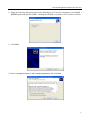
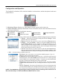
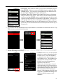
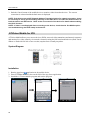
1
Remote Management Software (ATVision Pro) Table of Contents Chapter 1 ─ Overview................................................................................... 1 1.1 In This Manual ................................................................................... 1 1.2 ATVision Pro Features ....................................................................... 1 1.3 Product Information ........................................................................... 1 Chapter 2 ─ Installation ................................................................................ 3 Chapter 3 ─ Configuration ............................................................................ 7 3.1 3.2 3.3 3.4 Screen ............................................................................................... 7 Panel ................................................................................................. 8 Menu ................................................................................................ 14 Toolbar ............................................................................................ 29 Chapter 4 ─ Operation ................................................................................ 31 4.1 4.2 4.3 4.4 4.5 Live Monitoring ................................................................................ 31 Playback and Search ....................................................................... 33 Additional Functions ........................................................................ 40 Panic Recording .............................................................................. 41 Status View ...................................................................................... 42 Appendix A ─ Reviewing Video Clips ......................................................... 45 Appendix B ─ DVR Name Service (DVRNS) .............................................. 49 Appendix C ─ Map Editor ........................................................................... 50 Appendix D ─ Monitoring Using Mobile Devices ......................................... 55 i User’s Manual ii Remote Management Software (ATVision Pro) Chapter 1 ─ Overview 1.1 In This Manual This manual describes installation and operation of ATVision Pro (Remote Management Software) software, which is designed to be used with remote digital video recorders (DVRs, network video transmitters and network cameras included). 1.2 ATVision Pro Features ATVision Pro program is an integrated software program that controls system management, video monitoring, video recording and image playback of multiple remote sites. ATVision Pro offers the following features: Checks and reports status of remote DVRs Notification of events detected at remote sites Remote monitoring of live camera images Panic recording of monitored images Time-lapse and event search of recorded images Remote software upgrades and system programming View system and event log information of remote DVRs Remote monitoring of multiple remote sites using maps Connect up to 64 remote sites (up to 16 remote sites for remote search) at a time NOTE: This product includes software developed by the OpenSSL Project for use in the OpenSSL Toolkit (http://www.openssl.org/). NOTE: The software included in this product contains some Open Sources. You may obtain the complete corresponding source code from us. See the Open Source Guide on the software CD (OpenSourceGuide\OpenSourceGuide.pdf) or as a printed document included along with the User's Manual. 1.3 Product Information Package Components User’s Manual (this document) Installation CD System Requirements Operating System: Microsoft® Windows® XP x86 (32 Bit) (Service Pack 3), Microsoft® Windows® Vista x86 (32 Bit) (Service Pack 1), Microsoft® Windows® 7 or Microsoft® Windows® 8 CPU: Intel Pentium IV (Celeron) 2.4GHz or faster RAM: 512MB or higher VGA: AGP, Video RAM 8MB or higher (1024x768, 24bpp or higher) 1 User’s Manual 2 Remote Management Software (ATVision Pro) Chapter 2 ─ Installation CAUTION: If an older version of ATVision Pro software is installed in your computer, you should uninstall the older version first. NOTE: In the Windows Start menu, go to Control Panel. Double click the Power Options to open the Management Properties dialog box. Under the Power Schemes tab, set both Turn off monitor and Turn off hard disks to Never. 1. Insert the installation CD. 2. Run the Setup.exe file. NOTE: Run the file as the administrator user, otherwise the installation will fail. If you have logged on as other user, you will be asked to enter the administrator user name and password when running the file. NOTE: The User Account Control window might appear when using Microsoft Windows Vista or later operating system. Click Allow and install ATVision Pro software following the instructions. 3. The .NET Framework and the Visual C++ Runtime Libraries are installed automatically. NOTE: Installing the .NET Framework and the Visual C++ Runtime Libraries is required for ATVision Pro to operate properly. This installation step will be skipped if they are already installed on your computer. 4. Designate the folder path to install ATVision Pro and select the user(s) who can use ATVision Pro. Then click Next. 3 User’s Manual 5. When the following dialog box appears, click Next. 6. Click Next. 7. Select whether or not to run ATVision Pro automatically when logging onto Windows, and then click Next. 4 Remote Management Software (ATVision Pro) 8. When the following dialog box appears after finishing the ATVision Pro installation, select Install MSXML application and click Finish. Installing the MSXML is required for ATVision Pro to initiate. 9. Click Next. 10. Select I accept the terms in the License Agreement, and click Next. 5 User’s Manual 11. Enter User Name and Organization, and click Next. 12. Select Install Now and install MSXML following the instructions. 13. Click Close to complete the installation. 6 Remote Management Software (ATVision Pro) Chapter 3 ─ Configuration After installing the ATVision Pro software, you will find the ATVision Pro shortcut icon on the desktop. Run the ATVision Pro program by double clicking the icon. The ATVision Pro program consists of the screen, 12 docking panels, menu and toolbar. NOTE: Some panels will not be displayed on the screen in the default frame layout. To display those panels, open the View menu at the top of the screen and select each panel from the menu. 3.1 Screen The Screen displays images from selected cameras in the live monitoring or playback modes. ATVision Pro provides various multi-screen layouts; single-screen, quad, 1+7, 3x3, 4x4, 5x5, 1+32, 6x6, 7x7, 8x8 and full-screen. 7 User’s Manual NOTE: There might be a problem with screen display or screen update due to low image transmission speed when using Microsoft Windows Vista or later operating system. In this situation, it is recommended that you disable the Auto Tuning capability of your computer. Run the Command Prompt with elevated administrator permissions (Go to the Start Menu → All Programs → Accessories → Command Prompt → Click the right mouse button and select the Run as administrator option). Then enter “netsh int tcp set global autotuninglevel=disable” and click the OK button. Restart your computer to apply the changes. If you want to enable the Auto Tuning capability again, enter “netsh int tcp set global autotuninglevel= normal” after running the Command Prompt with elevated administrator permissions. Restart your computer to apply the changes. 3.2 Panel ATVision Pro has many powerful tools that can be used to streamline your work. Most of the tools are located on 12 docking panels that can be placed on the screen where they are most convenient. You can keep your screen free of clutter by displaying only the panels you use most frequently. Clicking the icon at the upper right corner of a panel enables the auto-hide feature. Tabs for auto-hidden panels are displayed on the edge of the screen. Scrolling over an auto-hidden panel tab will cause the panel to "fly" out. You can cause the panel to lock back into its original display position by clicking the icon. Clicking the icon hides the panel without a tab. Hidden panels can be displayed by selecting them from the drop-down menus. Panels can be resized, moved and combined with other panels creating a workspace that fits your needs. To resize a panel, scroll the cursor over the edge of the panel until the cursor changes to or . Then click the left mouse button and drag the panel border to enlarge or reduce its size. To move a panel to a different position on the screen, scroll the cursor over the title bar of a panel that has not been auto-hidden until it changes to . Once you click and drag, position arrows will display on the screen. The four position arrows along the outer edges allow you to place the panel along the given edge independent of the other panels. When you drag the panel over a position arrow, a transparent blue box will display showing the new panel position. If you are satisfied with the position, release the left mouse button and the panel will move to its new position. You can also move a panel so that it is associated with another panel. To do this, drag the panel over the panel you want it associated with, and the icon with four position arrows will center over that panel. Scrolling the cursor over the icon arrows will cause a transparent blue box to display where the panel will be located. If you are satisfied with the position, release the left mouse button and the panel moves to its new position. It is possible to combine panels so that they take up less space on the screen. Combined panels have a row of tabs across the bottom. Clicking a tab brings that panel to the foreground. To combine panels, move the cursor to the title bar of the panel you want to move. Click and drag the panel onto the panel you want to combine it with. If the panels can be combined, the four-position arrow icon will have a tab symbol in the center. Drag the cursor over the tab symbol , and a new tab appears on the panel. Release the mouse button and the panels will now be combined. The layout possibilities are virtually unlimited. With a little experimentation you will be able to lay out the screen so that it best meets your workflow. 8 Remote Management Software (ATVision Pro) Remote Sites Panel The Remote Sites Panel displays a list of remote sites registered during ATVision Pro System setup and a list of installed cameras at the remote sites. : Entering the site name in the query box and clicking the icon allows you to find the remote site easily in the Remote Sites list. : Clicking the icon allows you to register a remote site. : Clicking the icon removes the selected remote site from the list. : Clicking the icon allows you to edit the site information of the selected remote site from the list. To connect to a remote site, select the site or camera you want to connect to from the list and then drag and drop it in the desired position on the screen or the Status View panel. The screen displays images from selected cameras, and the Status View panel displays the system status information of the connected remote site. Selecting a site from the list and clicking the right mouse button displays a popup menu. Connect Status View: Displays the remote site status information in the Status View panel. Refer to 4.5 Status View for more details. Remote Setup: Allows you to change the setup of the remote DVR. Refer to 3.3 Menu – System Menu, Setup for more details. Remote System Log, Remote Event log: Displays the system log and event log information of the remote DVR. Refer to 3.3 Menu – Remote Menu for more details. Remote Desktop: Allows you to connect to the remote site using the VNC function. For this function to work, the VNC function must be enabled in the remote DVR and a port number and password for the VNC remote connection should be registered during the remote site registration at ATVision Pro. Refer to the user manual of the remote DVR for details about the VNC function. This function may not be supported, depending on the specifications and version of the remote DVR. Favorite Sites Panel The Favorite Sites panel displays the list of Favorite sites registered during ATVision Pro System setup. Selecting the Favorite site you want to connect to from the list and then dragging and dropping it in the desired position on the screen connects all remote sites registered in the Favorite site automatically. 9 User’s Manual Map Panel The Map panel allows efficient monitoring of the remote sites by displaying a map of the selectable site. Click the right mouse button on the map panel to select the map image file (.rmp) you want to monitor from the list. The selected map image displays in the Map panel and the sites registered on the map image file will be connected. When the selected map is linked with sub-maps, clicking the linked image moves to the sub-map. NOTE: Refer to Appendix C – Map Editor for details on editing maps. The Map panel pops up another screen when alarm-in, motion or video loss events are detected or when you click the device icon according to the Map Editor settings. Change the popup screen location by clicking the left mouse button on the screen and dragging it to where you want it located. Clicking the right mouse button on the popup screen displays the following popup menu. x0.25 to x2: Sets the desired size of the Map popup screen. Draw Motion Block: Displays the area that detects motions on the screen. (Network Video Transmitter connection only) Full Screen: Enters the full-screen mode of the Map popup screen. Transparency…: Adjusts the transparency of the popup screen. PTZ Set…: Controls pan, tilt and zoom of the selected PTZ camera. Disable Time Out: Continues displaying the popup screen when events are detected by disabling the dwell time out. Original Ratio: Displays the Map popup screen by matching its original aspect ratio. Anti-Aliasing Screen: Enhances image display quality on the popup screen by smoothing stair stepping (aliasing) effects in the enlarged image. User Set…: Sets the mode of the current popup screens displayed on the monitor. For example, the monitor displays the current popup screen with enough frames for 16 cameras when you select 4x4. NOTE: Refer to Appendix C – Map Editor, Device Setting section for more details about the popup function. To connect to the remote site, select the device you want to connect to from the Map panel and then drag and drop it in the desired position on the screen or the Status View panel. Also, placing the mouse cursor on the device on the map displays the device status. When the device detects any event or the device is not working properly, the following status icons appear (maximum of 4). Unplugged Video Blind Alarm In Trip-Zone Event Off Motion Alarm Out Tampering Irregular Object Detection Video Analytics Detection Video Loss Audio Detection NOTE: The device status is displayed as Irregular based on to the system check settings and as each event according to the event detection settings on the remote DVR. NOTE: Some status icons may not be supported, depending on the specifications and version of the remote DVR. 10 Remote Management Software (ATVision Pro) Clicking the right mouse button on the Map panel causes a text menu screen to display. Selecting Watch Event View from the menu displays the event information of the connected remote sites. Selecting Close disconnects the current connection on the Map panel. PTZ, Color and Alarm Out Control Panels Three panels allow PTZ control, color control, and alarm out control while live monitoring a remote site. NOTE: Refer to 4.1 Live Monitoring for more details. Image Processing Panel The Image Processing panel allows enhancing played back images. NOTE: Refer to 4.2 Playback and Search for more details. Watch Event View Panel The Watch Event View panel displays events detected at individual remote sites while ATVision Pro is in the live monitoring mode. The description of event icons is as follows: 11 User’s Manual Alarm-In On Object Detection Text-In Disk S.M.A.R.T. Disk Almost Full Panic Recording On Fan Error Off System Restart Audio Detection Alarm-In Off Video Loss Alarm-In Bad Disk Bad Disk Config Change Panic Recording Off System Boot Up System Shut Down Trip-Zone Motion Detection Video Blind Recorder Bad Disk Full Disk Temperature Fan Error On System Alive Video Analytics Detection Tampering NOTE: Some event icons may not be supported, depending on the specifications and version of the remote DVR. Emergency Event View Panel The Emergency Event View panel displays a list of events (preset for notification at the remote site) that were called from individual remote sites (LAN connection only). Selecting an event from the list and then dragging and dropping it in the desired position on the Watch or Search screen connects to the remote site, and a checkmark is placed in the box at the left. Selecting an event or site from the list and then clicking the right mouse button causes a tooltip to appear, which contains the emergency event instruction from the remote site. NOTE: The Emergency Event View function is available only for the remote sites that were set to notify the ATVision Pro system when configuring each event setup. Report View Panel 12 Remote Management Software (ATVision Pro) The Report View panel displays the system status information of remote sites. ATVision Pro checks the remote site and reports system status. Clicking the icon on the panel reloads the data and clicking the icon prints the report out. Report Setup must be configured during ATVision Pro System setup for this feature to function. Refer to 3.3 Menu – System Menu for more details. NOTE: Some report options may not be supported, depending on the specifications of the remote DVR. Search View Panel The Search View panel allows time-lapse or event searching of recoded data on the remote DVR. NOTE: Refer to 4.2 Playback and Search for more details. Status View Panel ATVision Pro provides a status display, remote setup, system log and event log view of the connected remote site in real-time. To display a status of the remote site, select a camera or a site from the Remote Site list and drag it to the Status View panel. You can also select Connect Status from the popup menu displayed by clicking the right mouse button after selecting the site from the Remote Site list. NOTE: Refer to 4.5 Status View for more details. 13 User’s Manual 3.3 Menu System Menu Setup: Allows setting up the system operation and remote site configuration. System 1: Set up the date/time format for ATVision Pro, display option, and panic recording function. Date/Time Format: Set the date/time format. Display Option: Set up the screen display, drag & drop popup option, display acceleration and OSD. 14 Remote Management Software (ATVision Pro) – Screen Option: Select Watch Screen to use the screen for live monitoring only, Search Screen to use the screen for search only, or Watch and Search Screen to use the screen for both live monitoring and searching. Selecting Hide the Message Box hides the message box that displays the status information about ATVision Pro and remote site connections. – Drag & Drop Popup Option: Select which mouse button will be used when displaying popup menu screens from Use Left Mouse Button, Use Right Mouse Button or both (Watch and Search Screen mode only). – Drawing Mode Setup…: Set up the display options for the screen. Normal Drawing: Depends on your PC’s CPU performance and displays images in low speed (DIB Draw Mode). Fast Drawing (Default): Displays image in normal speed (Direct Draw Mode). Fast Drawing (YUV420/RGB32): Depends on your PC’s video card performance and displays images in high speed (Direct Draw Mode). Overlay (YUV420/RGB32/RGB565): Displays image in high speed (Direct Draw Overlay Mode). Deinterlacing: Set up the deinterlace filter. Using a deinterlace filter for interlaced video enhances image display quality by eliminating horizontal scan lines and noise in areas with motion. Aspect Ratio: Set up the image aspect ratio displayed on the screen. Selecting Fit to Screen displays images by fitting them to the screen size, and selecting Original Ratio displays images by fitting them within the screen size while maintaining their original ratio. Anti-Aliasing Screen: When using the option, the image display quality on the screen will be enhanced by eliminating stair-stepping (aliasing) effects in the enlarged image. Use Slow Connection Draw Mode: When using the option in slow network environments such as ADSL and connecting to a remote site in the live monitoring mode, the time taken to display the first image on the screen will be reduced. NOTE: If the image cannot be displayed properly because of your PC’s specifications, lower the drawing mode level. NOTE: While in the Fast Drawing mode, the drawing speed might decrease when the ATVision Pro screen is not located on the primary monitor. NOTE: Overlay drawing mode may not be supported, depending on the type of video card installed in your PC. Video cards with an ATI chipset are recommended. NOTE: When using dual monitors, selecting Overlay drawing will display the image only on the primary monitor. NOTE: When using a low-end computer, image drawing speed might decrease while using a deinterlace filter depending on the type of deinterlace filter. NOTE: When using a low-end computer, image drawing speed might decrease when the Anti-Aliasing Screen option is selected. – OSD Setup…: Select options to display on the screen. – Load Default Map at Startup: Select whether or not the user-defined map file is loaded automatically when ATVision Pro starts, and designate the path of the map file (.rmp) to load. 15 User’s Manual Recording Setup: Set up the Use (On or Off) of the panic recording function and overwriting option of the recording folder (On or Off). When using the panic recording function and overwriting option, ATVision Pro continues recording when the hard disk drive is full by overwriting the oldest video. Designate a recording folder path and set the recording folder size from 640MB to 2,048MB. Capacity shows the remaining space of the recording folder. NOTE: The recording folder size cannot be changed once it has been set. Designate another recording folder path if you want to expand the recording space. – Recording Mode Setup…: Set up the panic recording mode. Visible Watch Camera: Records camera channels currently displayed on the Watch screen. User Assignment Setup: Records camera channels assigned by the user on the Watch screen. Camera Range Setup: Records camera channels within preset channel range. Select the boxes beside Camera and adjust camera range up to 16 channels. NOTE: Panic recoding will NOT be made for the cameras currently not displayed on the Watch screen even though they are set up to be recorded. NOTE: When selecting the User Assignment Setup mode, the user can assign camera channels to record manually on the Watch screen. Select a camera on the Watch screen and click the right mouse button then select Set Record Camera in the text menu screen. The gray icon displays on the selected camera screen. 16 Remote Management Software (ATVision Pro) System 2: Set up the modem connection information for remote access, system password, network option, report function and DVRNS server. Security Options: Designate whether password confirmation is required Before setup, Before startup, or Before shutdown of ATVision Pro. Click the Change button to change the password. Network Option: Set up the IP port number that is used for network connection when receiving a callback message from a remote site, and the upgrade port number that is used for upgrading the PC-based DVR. Select Use modem if you want to use a modem for remote access. NOTE: The IP port and upgrade port numbers you enter should match the values set during the network setup of the remote DVR. – Event Setup…: Enter the number of emergency events displayed in the Emergency Event panel. Set up ATVision Pro to sound when events are detected by selecting events from the list and designating the sound file (.wave) path. You can set up a different sound for each type of event. Report Setup: Set up the Use (On or Off) and check intervals (from 1 to 24 hours) of the report function. When using the report function, ATVision Pro checks on the remote site based on the user-defined interval and reports system status. DVR Name Service: Set up the IP address and port number of the DVRNS (DVR Name Service) server. The IP address and port number you enter should match the values set during the DVRNS setup of the remote DVR you want to connect to. NOTE: The DVRNS server cannot be configured when using modem connections. Refer to Appendix B for more details on DVR Name Service. Remote Desktop Option: Select Use the default password for remote desktop connection and enter the password to use the same password for every remote site when connecting to remote sites using the VNC function. In this case, the password registered in the Remote Desktop Setup setting during the remote site registration will not be used. This setting will be used when every remote site uses the same password for the VNC remote connection. 17 User’s Manual Remote Site: Configures the connection list for remote access. Add: Click the Add button and enter the information about the remote site you want to add. – Reference Group: The site should be assigned to a Reference Group for effective management of multiple remote sites. Click the Add button to create a new reference group. – Device Setup: Select the system of the remote site to register. When registering an IP camera, select IP Camera. – Remote Site Setup: Select PC Based DVR when registering a DVR at the remote site that is PC based. Enter a site name and the IP address of the remote site (modem telephone number for dial-up connections), acquired from your network administrator. Click the Port… button to set up the IP port number of each program. The IP port number should match the value set during the network setup of the remote DVR. If the remote system version does not allow you to set the IP port numbers, use the following values: “8200” for Admin, “8016” for Watch, “10019” for Search, and “8116” (“8115” for a PC-based DVR) for Audio. Select the number of cameras at the remote site. For example, selecting “8” from the list when registering a 16-channel DVR displays video of the first 8 channels on the screen. 18 Remote Management Software (ATVision Pro) NOTE: If the DVR uses the DVRNS function, place a checkmark in the Use DVRNS box. The IP Address field will be changed to DVR Name, and you can enter the name of remote site registered on the DVRNS server. The DVR name you enter should match the name set during the DVRNS setup on the remote DVR. – Login Setup: Enter the user ID and password. The user ID and password you enter should match the user ID and password used to log on to the DVR. If you have entered a user ID and a password, the site will be connected automatically without a dialog box requesting a password. Select No Password for remote systems that do not require a password (e.g., guest login). NOTE: Up to 32 characters may be used for the site names. – Remote Desktop Setup: Enter the port number and password set in the remote DVR for the VNC remote connection. Refer to 3.2 Panel – Remote Sites Panel for details about the VNC remote connection. If it is set up to use the same password for every remote site, you cannot enter the password here. Refer to System 2 – Remote Desktop Option for details about using the same password. – Emergency Event Instruction: Enter the message to display when emergency events are called in from the remote site. The Emergency Event Instruction can be checked by clicking the right mouse button after selecting the event or the site from the list in the Emergency Event panel. Change: Select the group or site you want to change and click the Change button, or double click the group or the site to change. Then, edit the site information. Remove: Select the group or site you want to remove and click the Remove button. List All: Displays all registered remote sites. Find: Enter the group name or site name to search for and click the Find button to display the matching groups or sites in the list. 19 User’s Manual Favorite Site: The Favorite Site is a user-defined connection list that combines more than one remote site, so multiple sites can be monitored at the same time with a single connection. Add a new Favorite Site and define it by dragging and dropping sites and/or cameras to the Favorites map. Up to 64 cameras can be monitored at a time when each camera is assigned to its own position on the Favorites map. Favorites – Site Name: Select a registered Favorite site from the drop-down list. – ADD: Adds a new Favorite site. Clicking the button displays the Favorites dialog box. Enter the name of the Favorite site to add, and Select the desired screen layout used when the Favorite site is connected. – Change: Select the Favorite site to change from the Site Name list and click the Change button. Then change the site name or screen layout. – Remove: Select the Favorite site to remove from the Site Name list and click the Remove button. Connect Favorite Site at startup: Select whether or not your favorite site is automatically connected when ATVision Pro starts. Remove Selected Camera: Removes selected cameras from the Favorites map. Cameras can also be removed by clicking the right mouse button after selecting the camera. Remove All Cameras: Removes all cameras from the Favorites map. NOTE: Cameras can be selected by clicking the left mouse button on the camera in the Favorites map. Selected cameras will be outlined in red. Clicking the left mouse button on the camera while holding the Ctrl key toggles camera selection On and Off. Multiple cameras can be selected by clicking the left mouse button while holding the Shift key. NOTE: “[W]” (Watch Screen) and “[S]” (Search Screen) displayed to the left of the camera number indicates the display option of each camera. The display option can be selected when registering a Favorite site. Selecting the remote site from the Group List and dragging and dropping it to the Favorites map using the right or left mouse buttons (This is user-defined and must be set during System setup) displays the text menu screen. Select the desired display option between Watch Screen and Search screen. If you do not select the display option, Watch Screen display will be assigned to all cameras of the registered Favorite site by default. button on the toolbar will save the current screen layout of the Watch screen NOTE: Clicking the or Search screen directly to the Favorite site. NOTE: The Favorite Site list does not work with modem connections. 20 Remote Management Software (ATVision Pro) Sequence Site: Configure the sequence site. ATVision Pro connects to the registered sites sequentially allowing connection to more than one remote site. Register an Auto Sequencing group and add desired sites in the Group List to the Auto Sequencing group. Video from the sites added to the Auto Sequencing group is displayed on the screen in the preset sequence interval during the sequence monitoring. Sequence Dwell Time: Displays the preset sequence intervals (from 5 seconds to 1 hour) for each connection to the sites registered in the Auto Sequencing group. You also can change the preset sequence interval. Auto Sequencing: Displays the list of registered Auto Sequencing groups. You can add a new group (max. 20), change the Auto Sequencing settings of a group or delete the group by using the popup menu displayed by selecting the Auto Sequencing group and clicking the right mouse button. Add: Select the site to add from the Group List and click the Add button. Select an Auto Sequencing group to add the site from the popup menu displayed by clicking the button. Add All: Adds all sites in the Group List to the Auto Sequencing list. Select an Auto Sequencing group to add all sites from the popup menu displayed by clicking the button. Remove: Select the site to remove from the Auto Sequencing list and click the Remove button. Remove All: Removes all sites in the Auto Sequencing list. NOTE: The Auto Sequencing list is not valid with modem connections. Load Setup File: Allows applying the settings of the System – Setup menu saved as an .xml file format to the ATVision Pro system. Loading the setup file can also be performed by clicking the button on the toolbar. 21 User’s Manual Save Setup File: Allows saving the current settings of the System – Setup menu as an .xml file format. If you select specific remote sites, it only saves the settings for the selected remote sites. Saving the setup file can also be performed by clicking the button on the toolbar. Batch Job Setup: Allows upgrading or setting up multiple remote DVRs using the Batch Job Setup screen. Upgrade: Sets up the remote upgrade job for remote sites. First, select the remote sites to upgrade from the Group List, and add them to the Upgrade Sites list by clicking the Add button. Then, click the Upgrade Now button to initiate the remote upgrade job for listed Upgrade Sites. Add: Select the site to add from the Group List and click the Add button. Add All: Adds all sites in the Group List to the Upgrade Sites list. Remove: Select the site to remove from the Upgrade Sites list and click the Remove button. Remove All: Removes all sites in the Upgrade Sites list. Upgrade Now: Upgrades the software on the Upgrade Sites. NOTE: When upgrading a PC-based DVR, select PC Based DVR and then select the desired upgrade folder. 22 Remote Management Software (ATVision Pro) Setup: Imports saved settings from a remote DVR to the remote DVR. First, select a remote site to set up from the Group List, and add it to the Setup Sites list by clicking the Add button. Then, click the Setup Now button. Add: Select the site to add from the Group List and click the Add button. Add All: Adds all sites in the Group List to the Setup Sites list. Remove: Select the site to remove from the Setup Sites list and click the Remove button. Remove All: Removes the site from the Setup Sites list. Setup Now: Clicking the button and selecting a setup file applies the settings to the remote DVR in the Setup Sites list. NOTE: When importing saved settings to more than one remote DVR, network settings will not be imported; this feature may not be supported, depending on the specifications and version of the remote DVR. NOTE: This feature is NOT supported for PC-based DVRs. Disconnect: Disconnects all current connections. Disconnection can also be performed by clicking button on the toolbar. the View Log: Displays log information saved in the ATVision Pro system. NOTE: You can also display the Log Viewer screen by selecting Log Viewer from the ATVision Pro options under the Start menu in Windows. 23 User’s Manual View Log: Displays the type of log and the number of log entries of ATVision Pro. Selecting a log type from the list displays all entries of the selected log type, and you can search for the desired log by setting up a search filter. Filter: Set up the search condition. – Search Time: Set up the time range to search within. Selecting Current Time and the desired period searches for logs from the current time and as far back as the selected time span. Selecting Detail Time allows you to set up a specific starting and ending time to search within. – Detail Condition: Set up the desired search parameters. Select a filter target from the second list, and select a filter from the third list (enter a filter in the text box). Then select a comparison operator from the last list; Equal to search for logs that satisfy the condition (case sensitive), Not Equal to search for logs excluding logs that satisfy the condition, Like to search for logs that include the entered keyword or Not Like to search for logs that do not include the entered keyword. Clicking the Add Condition button allows you to add more search conditions. Selecting AND searches for logs satisfying all conditions. Selecting OR searches for logs satisfying at least one of the conditions. Search: Displays log entries satisfying the preset search filter. Reset: Resets the search filter. File 24 Log File Open: Opens a log file (.db). Delete Log: Deletes logs older than a certain age. Save As…: Saves the log information in the list as a text (.txt) or CSV (.csv) file. Print: Prints the log information. Close: Closes the Log Viewer screen. Remote Management Software (ATVision Pro) Exit: Disconnects all current connections and exits ATVision Pro program. View Menu Displays or closes the toolbar and panels. Remote Menu NOTE: The Remote menu can also be activated by clicking the right mouse button after selecting the remote site on the Remote Sites panel. Remote Setup: Allows you to change the setup of a remote DVR. Select the remote site on the Remote Sites panel, initiate the Remote Setup menu, and the setup screen displays. NOTE: Refer to the user manual for the remote DVR for more details on system setup. Remote System Log/Remote Event Log: Displays the system log and event log information of a remote DVR. Set the time range of interest and click the Find button. The log entries within the time range displays in the list. 100 results can be displayed in a single page. Click the Move buttons to display additional results. 25 User’s Manual From: Adjust the search starting date and time. When First is selected, it will search from the first logged item. To: Adjust the search ending date and time. When Last is selected, it will search to the last log. Find: Displays remote log entries within the selected period. Print...: Prints the log information. Save...: Saves the log information as a text or CSV file (UTF-8 encoded). Move Buttons: Moves to the first page ( ), previous page ( ), next page ( ) or last page ( ). You can go directly to a log page by clicking the page number button. Close: Closes the Log dialog box. Favorite Menu NOTE: The Favorite menu can also be accessed using the toolbar controls. Saves the current screen layout directly to the Favorite site. Sequence Menu NOTE: The Sequence menu can also be accessed using the toolbar controls. Starts or ends auto sequencing (Watch Screen Only). Clicking Auto Sequencing On allows you to select a desired Auto Sequencing group. 26 Remote Management Software (ATVision Pro) Record Menu NOTE: The Record menu can also be accessed using the toolbar controls. Starts or ends panic recording. Selecting Record Play initiates the RecordPlayer program and plays recorded video. Refer to 4.4 Panic Recording for more details. Image Menu NOTE: The Image menu can also be accessed using the toolbar controls. Save: Saves the current image as a bitmap (.bmp) or JPEG (.jpg) file. Print: Prints the current image. NOTE: Refer to 4.3 Additional Functions for more details. Layout Menu NOTE: The Layout menu can also be accessed using the toolbar controls. Screen Layout 27 User’s Manual Select the desired screen layout using the layout toolbar. When changing the screen layout, the selected camera on the current screen will be located in the first cell of the new layout. When in one of the multiview formats, selecting Previous Cameras or Next Cameras will move to the previous or next page. In other words, when viewing Cameras 1 to 4 in the quad format, selecting Previous Cameras will display Cameras 61 to 64 and selecting Next Cameras will display Cameras 5 to 8. Selecting Full Screen enters the full-screen mode. To return to the previous screen mode, press the Esc key on the keyboard or select FullScreen Close (x) from the popup menu displayed by clicking the right mouse button. Frame Layout – Layout Load: Select the desired frame layout and click the Load button to apply the selected frame layout to ATVision Pro. Default Layout: Displays the panels that are used most frequently in the Watch and Search screen modes. Admin Layout: Displays only the panels that are used most frequently in the Admin screen mode. Full Layout: Displays all the panels. Hide Layout: Hides all panels and displays only the screen. User Defined Layout: Displays the user-defined layout. – Layout Setup: The user can configure the frame layout by displaying panels on the screen where they are most convenient. Set up the user-defined frame layout. Always Load Layout at ATVision Pro Startup: Select whether or not the selected frame layout loads automatically when ATVision Pro starts. Save: Enter a layout name and click the Save button to save the current frame layout as a new user-defined layout. Rename: Select the layout to change from the Layout List and click the Rename button. Then change the layout name. Delete: Select the layout to delete from the Layout List and click the Delete button. NOTE: Up to 10 user-defined layouts can be saved. 28 Remote Management Software (ATVision Pro) Help Menu Displays ATVision Pro version information. 3.4 Toolbar The Toolbar allows convenient access to desired functions. The controls on the toolbar perform functions as described below: Disconnect Batch Job Setup Save ATVision Pro Setup Log Print Load Setup File Save Favorite Sites Panic Recording Save Setup File Auto Sequence Play Select the desired screen layout using the layout toolbar. When changing the screen layout, the selected camera on the current screen will be located in the first cell of the new layout. When in one of the multi-view formats, clicking the or button will move to the previous or next page. Clicking (Layout Load) will apply the selected frame layout to ATVision Pro, and clicking Setup) allows you to set up the user-defined frame layout. (Layout 29 User’s Manual 30 Remote Management Software (ATVision Pro) Chapter 4 ─ Operation 4.1 Live Monitoring ATVision Pro provides remote monitoring functions for viewing video images in real time from either a single site or multiple sites. In addition, when events are detected at a remote site while in the live monitoring mode, ATVision Pro displays the event information on the Watch Event View panel. In order to perform live monitoring, the display option must be set to Watch Screen or Watch and Search Screen during System setup. To connect a remote site on the Watch screen, select the site or camera you want to connect to in the Remote Site, Favorite Sites or Map panel and then drag and drop it in the desired position on the screen. The icon will be displayed on each Watch screen. To disconnect the current connection, select the site or camera you want to disconnect to in the Remote Sites, Favorite Sites or Map panel or on the screen and then click the button on the toolbar or select Disconnect from the System drop-down menu. NOTE: Some DVR models will only transmit images to the ATVision Pro system while recording video. NOTE: When selecting the display option of Watch and Search Screen during System setup, the remote site can also be set to connect using the right or left mouse buttons (This is user-defined and must be set during System setup). Select Watch Screen to connect to the selected site on the Watch screen when the text menu screen appears. Screen Layout and Frame Layout ATVision Pro provides multiple screen layout options. The formats available are single-screen, quad, 1+7, 3x3, 4x4, 5x5, 1+32, 6x6, 7x7, 8x8 and full-screen. When in one of the multi-view formats, clicking the or button will move to the previous or next page. To view a specific image in the single-screen mode, move the cursor to that image and double click the left mouse button. To return to the previous screen mode from the single-screen mode, double click the left mouse button in the monitoring window. Clicking (Layout Load) will apply the selected frame layout to ATVision Pro, and clicking Setup) allows you to set up the user-defined frame layout. (Layout Audio Communication ATVision Pro supports audio communication between the ATVision Pro system and the remote site equipped with two-way audio. If you want to enable audio communication with the remote site, select any camera of the remote site on the screen and click the right mouse button. Selecting Enable Audio from the menu displays the following audio control panel. NOTE: The icon will display on each camera screen when audio communication is available between the ATVision Pro system and the remote site. 31 User’s Manual If you want to send audio to the selected remote site, click the button and talk into the microphone. If you want to monitor live audio from the selected remote site through the attached speaker, click the button. Clicking both button and button allows two-way communication. Clicking the button disables audio communication. If the remote DVR allows you to select an audio channel to monitor from the ATVision Pro system, clicking the button displays the Select Audio Channel dialog box. Select a camera channel associated with an audio channel to monitor and click the OK button. Sequence Monitoring Clicking the button on the toolbar and selecting a desired Auto Sequencing group connects to the registered sites sequentially allowing connection to more than one remote site and displays images from selected cameras. Clicking the button during sequence monitoring releases sequence monitoring and maintains the current connection. For sequence monitoring to function, the sequence sites should be registered during System setup. Refer to 3.3 Menu – System Menu for details on configuring the sequence site. NOTE: While in the sequence monitoring mode, you cannot manually connect to sites by dragging and dropping with the mouse. Color Control ① Brightness ② Contrast ③ Saturation ④ Hue ⑤ Undo Adjust the brightness, contrast, saturation and hue of live video for each camera by clicking the target icons on the Color Control panel. Clicking the icon cancels the image processing operation and reloads the original image. Only the users authorized for color control can adjust the image at ATVision Pro. NOTE: It is important that cameras are properly adjusted. These adjustments cannot make up for improperly adjusted cameras when the images are recorded. NOTE: Not all DVRs support the color control at ATVision Pro. Refer to the user manual of the DVR. PTZ Control ① ③ ⑤ ⑦ Move buttons Focus Near/Far View Preset/Set Preset Advanced Menu ② Zoom Out/In ④ Iris Close/Open ⑥ Auto Focus Select a PTZ camera at the remote site, and control pan, tilt and zoom. Only the users authorized for PTZ control can control PTZ at ATVision Pro. The icon will display on each camera screen when PTZ can be controlled remotely. 32 Remote Management Software (ATVision Pro) NOTE: Control features of the Advanced menu will be enabled when a camera connected to a DVR supports PTZ features such as Speed, Auto Pan, Tour, etc. and the DVR supports remote PTZ control. Depending on the specifications of the PTZ camera, some features of the Advanced menu may not be active. NOTE: Clicking the (Device Menu) button functions the same as when selecting the Device menu feature of the Advanced menu. NOTE: When live video is out of focus after the camera is moved or video is zoomed in or out, clicking the (Auto Focus) button adjusts the focus automatically (some models of Network Camera connection only). NOTE: Using the mouse for PTZ control is supported. Click the left mouse button on the image and move that image in the direction you want to by dragging the mouse. Use the mouse wheel to zoom in and out. NOTE: Not all DVRs support the PTZ control at ATVision Pro. Refer to the user manual of the DVR. Alarm Out Control Control alarm out devices or beep on the remote DVRs by clicking the ON or OFF buttons. Only the users authorized for alarm out control can control an alarm out at ATVision Pro. NOTE: Not all DVRs support the alarm out control at ATVision Pro. Refer to the user manual of the DVR. 4.2 Playback and Search ATVision Pro allows you to play back and search recorded images on remote DVRs. It also provides additional functions including zoom, various image enhancements, image saving and image printing. To use remote playback and search functions, the display option must be set to of Search Screen or Watch and Search Screen during System setup. To connect a remote site on the Search screen, select the site or camera you want to connect to in the Remote Site or Favorite Sites panel and then drag and drop it in the desired position on the screen. The icon will be displayed on each Search screen. The remote site connection on the Search screen will automatically be disconnected if there is no activity for a specified amount of time. Click the button on the toolbar or select Disconnect from the System drop-down menu to disconnect the current connection manually. NOTE: Connecting to a Favorite site will be available if the Search Screen display option was set up to connect to selected Favorite sites. Refer to 3.3 Menu – System Menu for more details on Favorite Site setup. NOTE: When selecting the display option of Watch and Search Screen during System setup, the remote site can be also be set to connect using the right or left mouse buttons (This is user-defined and must be set during System setup). Select Search Screen to connect to the selected site on the Search screen when the text menu screen appears. It is possible to display cameras in both the Watch Screen mode (live view) and Search Screen mode at the same time. For example, you can connect to a remote DVR site with nine cameras. Drag and drop the site into the first frame on the viewing screen and select Watch Screen. Live video will display in the first nine frames on the screen. Then, drag and drop the site into the 10th frame on the viewing screen and select Search Screen. You will be able to view any video recorded on the remote DVR in frames 10 through 18. 33 User’s Manual Search View Panel The Search View panel consists of playback and search controls, time-lapse search table, and event search table. The playback buttons on the Search View panel perform the following functions as described below: Go to the First Image Stop Fast Forward Play Fast Backward Play Play Go to the Last Image Go to the Previous Image Go to the Next Image NOTE: The speed of fast forward depends on network bandwidth and the number of images per second recorded. You can control the playback speed of images that are currently being played back by using the control slider. You can control the fast forward or fast backward playback speed of images that are currently being played back fast forward or fast backward by using the control slider. You can display the selected image on the screen in its original size by clicking the button. Clicking the button again displays the image in the preset aspect ratio. You can enlarge a specific part of the image up to five times using the control slider. The user can electronically pan and tilt within the enlarged image by dragging the image using the mouse. Click the left mouse button on the enlarged image and drag to move its position. Clicking the button cancels the enlargement and resets the image. You can change the brightness of the current image using the control slider. Clicking the button cancels the brightness changes and resets the image. NOTE: Zoom in/out and brightness control work only while in the pause mode. Search Mode ATVision Pro supports two search modes: time-lapse mode and event mode. The time-lapse search mode searches for recorded data by time and then plays back images found within the time parameters. The event search mode searches for event log entries using specific conditions and plays back the images associated with those event entries. These two modes have different panel configurations and search methods. NOTE: Using both search modes at the same time is NOT possible. 34 Remote Management Software (ATVision Pro) Time-Lapse Search Click the button on the Search View panel to enter the time-lapse search mode. Selecting a date from the calendar initiates the time-lapse search. The dates for which recorded images are available are enabled. When first entering the time-lapse search, the latest date with recorded images will be selected (highlighted) in the calendar. Click the (Reload) button to reload the date information. Recorded information available from the selected date will be displayed on the timetable. The recorded data are displayed by time and bar-shaped segments indicate there are recorded data during that time. Select a specific hour by clicking the mouse on the desired hour segment. NOTE: The timetable of the time-lapse search panel will differ depending on the model of remote DVR that is connected to ATVision Pro. The recorded data of all camera channels are displayed by time in one-hour segments and a yellow-highlighted segment indicates the selected time that will be played back. Select a specific hour by clicking the mouse on the desired hour segment, and video images will be played back starting with the first image captured within the one-hour segment. If the remote DVR’s time and date have been reset to a time that is earlier than some recorded video, it is possible for the DVR to have more than one video segment in the same time range. Click the (Segment) button and select the video segment you want to search. The active segment will be highlighted with pink, and the inactive segment will be highlighted with gray on the timetable. The recorded data of each camera channel are displayed by time in one-minute segments and a red vertical line indicates the selected time that will be played back. The color of the bar indicates different types of recording: Yellow for Pre-event, Purple for Event, Red for Panic, Orange for Irregular recording caused by temporary disconnection from the device, and Blue for Time-lapse. The supported types of recording are different depending on the specifications and version of the remote DVR. If the DVR has more than one video segment in the same time range, each segment will be separated by a yellow vertical line. 35 User’s Manual When searching video recorded on a PC-based DVR, the recorded data of each camera channel are displayed by time in one-minute segments. The color of the bar indicates different types of recording: Yellow for Pre-event, Cyan for Motion Detection, Lime for Object Detection, Purple for Video Loss, Brown for Video On, Red for Sensor, Gray for Text-in, and Blue for Time-lapse. To view an image from a specific time, click the (Go To) button and set up the date and time to search. Event Search button on the Search View panel to enter the event search mode. First, click the Click the and set up the search condition in the following Event Search dialog box. button, NOTE: The Event Search dialog box will differ depending on the specifications of the remote DVR. NOTE: The Text-In (Event Search – Text-In tab) search may not be supported, depending on the specifications and version of the remote DVR. Refer to the user manual of the remote DVR for details on the search criteria for the text-in search. 36 Remote Management Software (ATVision Pro) Set up the search criteria for the event search in the Event Search dialog box, and click the Find button. The results will be displayed in the event list. A total of 100 results can be displayed at a time. Click the (Query Next) button to display the next results. If you select an event in the list, the recorded data associated with that event will be displayed on the screen. The images may be played back using the playback buttons. When searching video recorded on a PC-based DVR, you can adjust the event dwell time from 1 second to 10 minutes. If you adjust the event dwell time, ATVision Pro will display the images of first queried event and ignore remaining events occurring during the preset period. NOTE: When First is selected for the search starting time, the search will be from the first recorded data. When Last is selected for the search ending time, the search will be to the last recorded data. Additional Functions Searching Data Source Click the button on the Search View panel to set up the data source to be searched. Search on Local: Searches recorded data on primary storage installed in the remote DVR. Search on Archive: Searches archived data on backup storage installed in the remote DVR. Search on Other: Searches recorded or archived data on storage used for another DVR then installed in the selected remote DVR. NOTE: The Search on Other option may not be supported, depending on the specifications and version of the remote DVR. Screen Layout and Frame Layout ATVision Pro provides multiple screen layout for playback. The available formats are single-screen, quad, 1+7, 3x3, 4x4, 5x5, 1+32, 6x6, 7x7 and 8x8 and full-screen. When in one of the multi-view formats, clicking the or button will move to the previous or next page. To view a specific image in the single-screen mode, move the cursor to that image and double click the left mouse button. To return to the previous screen mode from the single-screen mode, double click the left mouse button in the playback window. Clicking (Layout Load) will apply the selected frame layout to ATVision Pro, and clicking Setup) allows you to set up the user-defined frame layout. (Layout Image Processing The Image Processing panel allows enhancing played back images using processing controls. Blurs the image. Sharpens the image. Equalizes the image. Reduces the alias effect that occurs when using the zoom function. Reloads the original image. 37 User’s Manual Playing Recorded Audio ATVision Pro will play audio when it is in the single-screen layout while playing back recorded video that has recorded audio. Audio playback can be On or Off by selecting Enable Audio from the menu displayed by clicking the right mouse button on the screen. NOTE: Audio might be interrupted during playback because of network conditions and your PC’s performance. NOTE: Playing recorded audio may not be supported, depending on the specifications of the remote DVR. Save Clicking the button on the Search View panel saves recorded video. Save As Self-Player…: Saves any video clip of recorded data as an executable file. Set up the save parameters in the following dialog box. Click the Start button, and select Save in. Enter a File name and then select Save as type (.exe) for the video you are saving. Then click the Save button. NOTE: When more than one video segment exists in the same time range due to time overlap, a segment selection dialog box will appear and ask you to select the video segment you want to save from the segment list. Refer to the user manual of the remote DVR for details on time overlap. NOTE: When the data file reaches 2GB, you will be asked to continue saving by creating multiple files in 2GB units. If you do not want to be asked, select Don’t ask about file limit. NOTE: If you want to save the recorded data without including the Self-Player program, select Exclude Player. If you select this option, the file size will be smaller, and it will take less time to save, but you will need to run the Self-Player program which is included on the ATVision Pro installation CD to play the saved file. This feature may not be supported, depending on the specifications and version of the remote DVR. NOTE: The Save As Self-Player dialog box will differ depending on the specifications of the remote DVR. Save As Self-Player can be performed by using the button on the Search View panel. Selecting the desired time on the timetable and clicking the button sets the starting date (From), and selecting another time and clicking the button again sets the ending time (To). Save As Video…: Saves any video clip of recorded data in an AVI (Audio Video Interleaved) file format. Set up the save parameters in the following dialog box. Click the Start button and then set the file name. Clicking the Save button starts saving video. 38 Remote Management Software (ATVision Pro) NOTE: Selecting Include Audio Data includes audio data when saving video with recorded audio. This option is not available when more than one camera is selected. NOTE: When the data file reaches 2GB, saving stops. Selecting Limit File Size and adjusting the maximum file size causes saving to stop once the data file reaches the maximum file size setting. Selecting Save Split File saves video by creating multiple files in 2GB units or in the Max File Size units. NOTE: Selecting View Proceeding Frames displays a popup screen showing the video currently being saved. Motion Search Click the button on the Search View panel to search for motion in the recorded images on remote DVRs. NOTE: Motion Search is supported only in the single-screen mode. Record Period: Sets up the record period of images to search. Find Method: Selects a search method. – Motion Search: Searches for images with changes in the Detection Area between two consecutive images (for example, when there was movement). – Museum Search: Searches for images with changes which last for the Activation Time in the Detection Area when compared to the image displayed currently on the Search Screen (for example, when an object disappears). 39 User’s Manual Sensitivity: Sets the sensitivity of the change detection. The higher the number is, the more sensitive it is. Num of diff. block: Sets the minimum number of blocks that must be activated to be considered as a change (Motion Search only). Diff. % to ref. image: Sets the minimum proportion (%) of blocks that must be activated to be considered as a change (Museum Search only). Activation Time: Sets the duration that the change must last to be considered as a change (Museum Search only). If a change is detected but does not last as long as the Activation Time, the change is not considered as a change. (Detection Area Select/Clear): Sets the detection area on the Search Screen by selecting or clearing blocks. Search/Stop: Starts or stops searching. The last recorded image is displayed on the Search Screen. Next: Searching stops when the search results reach 100. Clicking the button continues searching. Reset: Resets the search condition. 4.3 Additional Functions Save Clicking the button on the toolbar saves the image currently displayed on the screen as a bitmap or JPEG file. By placing a checkmark in the box beside Include Image Info, text information about the site will be included when saving the image. Print Clicking the button on the toolbar prints the image currently displayed on the screen on a printer connected to your computer. By placing a checkmark in the box beside Include Image Info, text information about the site will be included when printing the image. Screen Menu Selecting a camera on the Watch or Search screen and clicking the right mouse button display the popup menu. Change Camera Title: Changes the camera name displayed on the screen. Leaving the Camera Title blank causes the camera name set up on the remote site to display. Changing the camera title does not affect the camera name set up on the remote site. Enable Audio: Enables audio communication with the remote site on the Watch screen (Two-way audio equipped remote sites only). Plays audio while playing back recorded video that has recorded audio on the Search screen. Refer to 4.1 Live Monitoring and 4.2 Playback and Search for more details. Aspect Ratio: Changes the image aspect ratio displayed on each camera screen. 40 Remote Management Software (ATVision Pro) – Fit to Screen: Displays images by fitting them to the screen size. – Original Ratio: Displays images by fitting them within the screen size while maintaining their original ratio. – Half Size (x0.5) to Quadruple Size (x4): Select the desired image size. Options are enabled when the selected camera screen can display images in that size. Draw Motion Block: Displays the area that detects motions with red blocks on the screen. (Network Video Transmitter connection only) Trim The Black(noise) Edges: Trims the black line (noise) displayed at the edge of the image. (Network Video Transmitter and some models of Network Camera connection only) MultiStream: Allows you to choose the desired stream if the remote DVR is in the multistream mode for live monitoring. Set Record Camera: Sets the selected camera channel to be recorded during panic recording. Refer to 3.3 Menu – System Menu for details on configuring camera channels for panic recording. Deinterlacing: Enhances image display quality of interlaced video on the screen by eliminating horizontal scan lines or noise in areas with motion. Anti-Aliasing Screen: Enhances image display quality for all cameras on the screen by eliminating stair-stepping (aliasing) effects in the enlarged image. Disconnect Camera: Disconnects a camera on the screen. NOTE: When using a low-end computer, image drawing speed might decrease while using a deinterlace filter depending on the type of deinterlace filter. NOTE: When using a low-end computer, image drawing speed might decrease when the Anti-Aliasing Screen option is selected. 4.4 Panic Recording Clicking the button on the toolbar starts panic recording of cameras currently displayed on the Watch screen. Clicking the button again stops panic recording. Up to 16 channels can be recorded at a time, and you can select which cameras are to be recorded during the System setup. Clicking the button on the toolbar initiates the Record Player program and plays video saved in the recording folder designated during the System setup. The Record Player GUI and its controls are almost identical to the Clip Player. Refer to Appendix A – Reviewing Video Clips, Clip Player. If you want to play back video saved in another recording folder, run the Record Player program first. Move to the Start menu in Windows. Then, select RecordPlayer from the ATVision Pro options and select the recoding folder path you want. Recorded video can be saved as a bitmap or as an executable file using the save function of the Record Player. NOTE: Panic recording will be available only if you select Use Recording and it is set up in the recording options during the System setup. NOTE: The date and time displayed on the Record Player indicates when the recording was made on ATVision Pro. NOTE: The icon will display on each screen when panic recording starts. NOTE: Audio recording is not supported. 41 User’s Manual 4.5 Status View ATVision Pro provides a status display, remote setup, system log and event log view of the connected remote site in real-time. To display a status of the remote site, select a camera or a site from the Remote Site list and drag it to the Status View panel. You can also select Connect Status from the popup menu displayed by clicking the right mouse button after selecting the site from the Remote Site list. Function Buttons Disconnect: Disconnects the current connection on the Status View panel. NOTE: If you want to connect to another site, disconnect from the currently connected system on the Status View panel first by clicking the button. Remote Setup: Allows changing the setup of the remote DVR connected to the Status View panel. NOTE: Refer to the manual for each applicable remote DVR for more details on system setup. Remote System Log: Displays the system log information of the remote DVR connected to the Status View panel. Remote Event Log: Displays the event log information of the remote DVR connected to the Status panel. NOTE: Refer to 3.3 Menu – Remote Menu for more details on the Remote System Log and Remote Event Log. NOTE: When the remote site is not connected to the Status View panel, Remote Setup, Remote System Log and Remote Event Log menus can be accessed by clicking the right mouse button after selecting the remote site on the Remote Sites panel. Remote Panic Control: Controls the panic recording of the remote DVR connected to the Status View panel. The (On) button indicates that the remote DVR is not in the panic recording mode and you can start panic recording by clicking the button. The (Off) button indicates that the remote DVR is in the panic recording mode and you can stop panic recording by clicking the button. NOTE: Remote Panic Control may not be supported, depending on the specifications and version of the remote DVR. Status Display Window The Status Display Window displays the event, alarm out, system check and recording status information of the remote system connected to the Status View panel in real-time. NOTE: Depending on the specifications of the remote DVR, status display may not be supported. Event: Displays event (Motion Detection, Alarm In, Object Detection, Video Blind, Audio Detection, Trip-Zone, Tampering). The status display of event detection will continue during the preset dwell time of the event-driven recording. 42 Remote Management Software (ATVision Pro) Event Detection No Event Detection Event Off Alarm Out: Displays status of the alarm-out signals. Alarm-Out No Alarm-Out Alarm-Out Off System Check: Displays the function status of the camera, alarm, and recording. Normal Irregular System Check Off Record From/To: Displays the record period. Status: Displays the recording, playback, archiving, clip-copy status. On Off Version: Displays the system version information. 43 User’s Manual 44 Remote Management Software (ATVision Pro) Appendix A ─ Reviewing Video Clips You do not need to install any special software on you personal computer to review video saved as Self-Player files. The file contains a Player program. Double-clicking the target file starts the Player program. NOTE: The Player GUI will differ depending on the model of the remote DVR that is connected to ATVision Pro when reviewing the video saved as a Self-Player file. MiniBank Player NOTE: It is suggested that the computer used for the MiniBank Player program has at least an 800MHz Pentium III. If your CPU is slower than this, video clips recorded at maximum speed with very high image quality will be played back slowly. The Monitoring Screen displays the backed up images. Click the right mouse button on the image to zoom in and click the right mouse button while holding the Ctrl key to zoom out. Scrolling the mouse wheel up or down on the image also zooms in or out. Clicking the right mouse button on the image while holding the Shift key switches the screen size. Click and hold the left mouse button and drag the image to move its position. Clicking the Quit button exits the Player program. Click the Save button to save the current image in a bitmap file format on the local hard disk drive or floppy disk. Click the Print button to print the current image on the printer connected to your computer. The Backup File Information window displays information regarding the backup file. Location displays the site description of the DVR where the backup was made. Record displays the time span of the video backup file. Encryption displays whether the backup file has been tampered with. Normal means the file has not been tampered with, Wrong means the system has detected tampering, and no mark means the user cancelled the encryption check. 45 User’s Manual The Current Image Information window displays information about the current image. Camera Title displays the camera name of the current image, and Time displays the date and time the image was recorded. The Image Search Slide Bar displays the current playback position. The user can move to another image by clicking the mouse and dragging along the slide bar. The Playback Function Buttons include fast backward, backward, play, pause, fast forward, go to the first image, go to the previous image, go to the next image, and go to the last image buttons. The Brightness Revert Button reloads to the original image. Clicking the Mute Button mutes the recorded audio. The Brightness Control Slide Bar adjusts the brightness of the backup images by clicking the mouse and dragging along the slider bar. Minute brightness changes can be made using the arrow buttons located at each end of the bar. Clicking the OSD (On-Screen Display) Button switches the OSD option. The OSD information includes camera location and date/time. Double clicking the Player logo at the top right corner while holding the Shift key switches video formats when you are experiencing improper image display. Clip Player NOTE: It is suggested that the computer used for the Clip Player program has at least an 800MHz Pentium III (Intel Pentium Dual Core 2.2GHz recommended). If your CPU is slower than this, video clips recorded at maximum speed with very high image quality will be played back slowly. Also DirectX 9.0 or higher is required to install, and the VGA card with 16MB or higher video RAM is recommended for proper operation. NOTE: If you selected the Save Password option when saving recorded video, you will be asked to enter the password to initiate the Clip Player program. NOTE: If you selected the Exclude Player option when saving recorded video, you must run the Self-Player program which is included on the ATVision Pro installation CD to play the saved file. The ClipPlayer Screen displays the clip images. 46 Remote Management Software (ATVision Pro) NOTE: Proper image display depends on the display settings of your PC. If you are experiencing display problems, click the right mouse button on the background screen and select Properties → Settings then set the Color quality to “32 bit”. Then select Advanced → Troubleshoot, and then set the Hardware Acceleration to “Full”. Please make sure that DirectX version 9.0 or higher has been installed if the display problem continues. To check the version of DirectX, click Start → RUN and type “dxdiag” then hit the enter key which will display DirectX Diagnostic Tool dialog box. Then move to the Display tab and make sure DirectDraw Acceleration is set to “Enabled”. Test DirectDraw by selecting ® ® the DirectDraw Test button when using the Microsoft Windows XP operating system. Please check the driver version of the video card and update it to the latest version available. If you still have display problems after changing all display settings as described above, try replacing the video card. Video cards with an ATI chipset are recommended. Clicking exits the Player program. Click to go to the beginning of the video clip. Click to play the video clip in fast reverse. Click to go back one frame of the video clip. Click to play the video clip. Click to go forward one frame of the video clip. Click to play the video clip in fast forward. Click to go to the end of the video clip. Click to show the previous camera group if there is recorded video in the previous camera group in the current screen mode. Click to cycle through the screen layouts. It cycles through 2x2, 1+7, 3x3, 4x4, 4x5, 5x5 and 1+32. NOTE: 4x5, 5x5 and 1+32 screen modes might not be supported depending on the number of saved camera channels. Click to show the next camera group if there is recorded video in the next camera group in the current screen mode. Click the icon to set up the Clip Player properties. Print: Prints the current image. Frame Info.: Displays Channel, Title, Time, Type, Size and Resolution information about the image. Image Processing: Controls brightness, blur and sharpness of playback images. (SingleScreen Layout and Pause Mode Only) Play Speed Control: Changes the playback speed (Play) or fast forward/backward playback speed (FF/RW). Drawing Mode: Selects the draw mode level. If you are not sure about the best draw mode level for your system, try each level until the image displays properly. Screen Size: Changes the Clip Player screen size. Aspect Ratio: Changes the image aspect ratio displayed on each camera screen. OSD Setup…: Selects options to display on the screen. Enable Audio: Plays audio while playing back recorded video that has recorded audio. (Single-Screen Layout Only) Anti-Aliasing Screen: Enhances image display quality on the screen by smoothing stairstepping (aliasing) effects in the enlarged image. If video plays slow because of your CPU’s slow speed, releasing the Anti-Aliasing Screen option might improve playback speed. Show Text-In: Displays text-in data if the video was recorded with text-in data. In the single-screen layout, text-in data is displayed with images on the screen. In multi-screen layouts, click the right mouse button on a camera screen and then a text-in menu. 47 User’s Manual Click the icon to save clip images. Save as Image: Saves the current image as a bitmap or JPEG file. Save as Image (Actual Size): Saves the current video frame as a bitmap or JPEG file in its actual size. (Single-Screen Layout Only) Save as Clip-Copy: Saves video of desired time range as an executable file. Save as Video: Saves video of desired time range as an AVI file. Clip-Copy Log: Saves the clip copy log information as a text file. The user information about Save As Clip Copy will be logged as “Internal-Copy”. Click the icon to enlarge the image or display the image in its actual size (Single-Screen Layout Only). You can move the enlarged image by clicking the left mouse button and dragging. Click the icon to display the image full screen. Click the icon and set up the date and time of a saved image to view the image from the specific time. Encryption icons display at the bottom-right corner. displays when the clip file has not been tampered with, and displays and playback stops when the system has detected tampering. NOTE: If the VGA card or monitor does not support 800x600 video resolution, Full Screen might not display properly. If this happens, press the ESC key on your PC keyboard to return to the normal screen mode. Click the slider bar and move it left or right to move through the video clip. Placing the mouse cursor on an image and clicking will cause that image to display full frame NOTE: Some options may not be available, depending on the specifications and version of the remote DVR. 48 Remote Management Software (ATVision Pro) Appendix B ─ DVR Name Service (DVRNS) Overview Using Static IP addresses in LAN/WAN networks requires high management overhead and increases the cost burden to users. Therefore, it has become essential for DVRs to support Dynamic IP addresses in ADSL/VDSL networks using DHCP (Dynamic Host Configuration Protocol). This reduces cost burdens and increases cost effectiveness for system users. Use the following steps to set up a system using DVRNS. System Configuration STEP 1 (DVR → DVRNS Server): Register the unit name and IP address of the DVR during the DVRNS setup on the Remote DVR. This unit name and IP address will be registered on the DVRNS server directly. NOTE: Refer to the applicable manual for each remote DVR for more details on DVRNS setup. STEP 2 (ATVision Pro → DVRNS Server): Request the IP address of the remote DVR using the registered unit name of the DVR you want to connect to. STEP 3 (DVRNS Server → ATVision Pro): The DVRNS server notifies ATVision Pro of the requested IP address. STEP 4 (ATVision Pro → DVR): Connect to the target DVR using the IP address returned from the DVRNS server. NOTE: You should follow steps 2 to 4 whenever connecting to the remote site because the DVR name and IP address might change at anytime. 49 User’s Manual Appendix C ─ Map Editor The Map Editor program allows you to create maps of remote sites. With the drag-and-drop and link function, you can create and edit the map easily and efficiently. Run the program by selecting MapEditor from the ATVision Pro options under the Start menu in Windows. Background Image Setting First, prepare the image in a bitmap or JPEG file format. Click the and select the background image of the map. (Background) button on the toolbar Go to the Property [Canvas] tab and set the background image information. Name: Enter a name of the background image. Horizontal/Vertical: Adjust the background image size by clicking each field and changing the numbers. Position: Adjust the position of the background image on the screen. Select Auto Fit to fit the map screen size to the background image. 50 Remote Management Software (ATVision Pro) Option Menu Click the Option menu to set up the remote site information, device status display and remote site name to display. Site Information Setting: Select the Site Information Setting… in the Option menu to set the information about the remote site connections, and the following Site Information setup window appears. Click the Add button, and the following Site Item box appears. Remote Site Setup: Enter the site name and IP address of the DVR connected to the devices you want to include on the map. Click the Port… button and enter the network IP port number (8000 to 12000) that matches the value set during the LAN setup on the DVR. Check the box beside Use DVRNS to use the DVR name service. NOTE: If you use DVR Name Service, you can enter the name registered on the DVRNS server instead of the IP address of the DVR, and you do not need to enter the network IP port number. Login Setup: Enter the user ID and password for the DVR associated with devices. DVRNS Server: Enter the IP address and port number of the DVRNS server, which matches the values set during the DVRNS setup on the DVR. Clicking the OK button saves the setting. Popup Dwell Time: Select Popup Dwell Time… in the Option menu to set the duration of the Map popup screen displayed when events are detected, and the following Popup Dwell Time window appears. Check the box beside Use Timeout and adjust the time out dwell from 1 second to 5 minutes. Selecting Display remaining time displays the remaining time out dwell on the Map popup screen. NOTE: Popup Dwell Time will be applied to all maps displayed on the map panel. Status Color Setting: Select the Status Color Setting… in the Option menu and the following Status Color window appears. You can set the device to display a unique color reflecting its status on the Map panel. 51 User’s Manual Check the box beside Color Use and select each status box to use. Click each selected status box and select the desired color. When done, click the OK button. Unplugged: Either connection to the remote site has failed, or Device No. for the device is not supported by the remote site. Event off: Event detection function is not set up. Irregular: The device is not working properly. Video Blind/Video Loss/Motion/Object Detection/Video Analytics/Audio Detection/ Trip-Zone/Tampering: The event is detected. Alarm In: Alarm in is detected. Alarm Out: Alarm out is detected. NOTE: Devices are displayed as Irregular based on the system check settings and as Video Blind/Video Loss/Motion/Object Detection/Video Analytics/Audio Detection/ Trip-Zone/Tampering, Alarm In, and Alarm Out based on the event detection settings on the remote DVR. NOTE: The device displays mixed color when detecting more than two statuses at the same time. Name Table: Select Name Table… in the Option menu to display the name instead of the IP address of the DVR on the Map panel, and the following Name Table setup window appears. Click the Display Name field of each IP address and enter the name of the DVR to display on the popup screen. Device Setting buttons on the toolbar displays the Camera, AlarmOut and AlarmIn tabs under Selecting the , , or the Image Bar. Select the icons, and drag and drop them at the desired locations on the background image. Go to the Property [Camera/AlarmOut/AlarmIn] tab and set the device information. General Name: Enter a device name. Description: Enter description of the device. Site Information: Select a proper site for the device in the list, and the Equipment 52 fields (User, Password, IP Address and Port) are filled automatically with the information set in Site Information Setting…. Image: Select an image of a device. Ratio: Adjust the size of the device image. X Coordinates/Y Coordinates: Adjust the position of the device image by clicking each field and changing the numbers. Horizontal/Vertical: Adjust the size of the device image by clicking each field and changing the numbers. Popup camera: If the selected device is an alarm-in device, you can associate a camera with the sensor by entering the camera name. The camera name you enter should be the same as the camera name entered under the Property [Camera] tab. The Map panel pops up another screen and displays images of the camera associated with the sensor on the popup screen when an alarm-in event occurs. Remote Management Software (ATVision Pro) Equipment IP Address/User/Password/Port: Each field is filled in automatically with the information (user ID, password, and port number) set in Site Information Setting…, or you can enter it manually. Device No.: Set the device number (1 ~ 32) for each device. If the selected device is a camera, Device No. changes to Camera No.. DVRNS Use: Select Yes to use DVR Name Service, and the DVRNS field appears. Enter the IP address (or domain name) and the port number of the DVRNS server, and the name of the DVR registered on the DVRNS server. NOTE: You should not select numbers that are not supported for devices on the remote DVR when selecting Device No. Otherwise, the map cannot detect the device and it displays the device status as Unplugged. For example, Device No. should be from 1 to 16 when the device is connected to a 16-channel DVR. NOTE: If you set the IP address and port number of the DVRNS server in Site Information Setting…, the DVRNS fields are filled with the information automatically. NOTE: The DVRNS function is supported only with the devices associated with a DVR providing the DVRNS (DVR Name Service) function. Go to the Event [Camera/AlarmOut/AlarmIn] tab and set the option for the devices. Event [Camera]: Selecting an event from a drop-down list and checking the Watch View Popup box set the Map panel to pop up another screen when an event occurs. Selecting Click from a drop-down list and checking the Watch View Popup box pops up another screen by clicking the mouse button on the camera icon on the Map panel regardless of event detection. Event [AlarmOut]: Checking the Switch on/off box controls the alarm-out remotely by clicking the alarm-out icon on Map panel. Event [AlarmIn]: Selecting Alarm-in Event from a drop-down list and checking the Watch View Popup box sets the Map panel to pop up another screen when an alarm-in event occurs. Selecting Click from a drop-down list and checking the Watch View Popup box pops up another screen by clicking the mouse button on the alarm-in icon on the Map panel regardless of event detection. NOTE: The popup camera should be associated with the alarm in device to use the popup function. Refer to the Device Setting – General, Popup camera section for the popup camera association. Link Setting (Link) button on the toolbar and place it on the screen linked with a sub-map. Then the Link Click the Map box appears. Select the individual link boxes by using the Ctrl key on the keyboard, and then adjust the size and position of the link box using a mouse, a keyboard or the icons shown below. Interval adjustment: Equalizes the distance between three or more selected boxes. Size adjustment: Equalizes the size of two or more selected boxes. Clicking the arrow keys while holding the Shift key on the keyboard changes the size of the selected boxes. Position adjustment: Arranges two or more selected boxes towards one direction or towards the center. Clicking the arrow keys while holding the Ctrl key on a keyboard changes the position of selected boxes. Cut, Copy, Paste: Cuts, copies or pastes the link box. 53 User’s Manual Go to the Property [Link] tab and set the properties of the selected link box. Name: Enter a name of the link box. Image: Double click the field and select an image to insert in the link box. Link Document: Double click the field and select a map to be linked with the link box. Ratio: Adjust the image size within the link box. X Coordinates/Y Coordinates: Adjust the position of the link box on the screen by clicking each field and changing the numbers. Horizontal/Vertical: Adjust the link box size by clicking each field and changing the numbers. Text Show: Select Yes to display the name of the link box on the selected image. Clicking the (Save) button on the toolbar saves the map. You can monitor remote sites by using the map. Refer to 3.2 Panel – Map Panel section for details. 54 Remote Management Software (ATVision Pro) Appendix D ─ Monitoring Using Mobile Devices NOTE: The following programs might not be supported, depending on the specifications and version of the remote DVR. RAS Mobile for PDA RAS Mobile for PDA allows you to access remote sites and monitor live video using the Windows Mobile based PDA anytime from virtually anywhere. NOTE: The RAS Mobile for PDA installation file is provided on the ATVision Pro installation CD and can be installed if RAS Mobile for PDA is supported for the remote DVR. PDA system requirements for using the RAS Mobile program are: Operating System: Microsoft® Windows® Mobile 5.x/6.x Processor: ARMv4 Core compatible processor Display: 240x240 pixel, 320x240 pixel or 640x480 pixel Memory: 4MB of storage memory / 96MB or more of RAM Wireless LAN: Support IEEE 802.11 Input Device: Touch screen Desktop PC: Microsoft® Windows® 2000/Sever 2003/XP (with Microsoft ActiveSync 4.5 or above), Vista/7 (with Microsoft Windows Mobile Device Center 6.1 or above) System Diagram Installation 1. Install the Microsoft ActiveSync or Microsoft Windows Mobile Device Center program on the PC in order to install the RAS Mobile program on the PDA. You can download the installation file from the following website: http://www.microsoft.com/windowsmobile/en-us/downloads/default.mspx 2. Connect the PDA to the PC. Click the OK button when the following message box appears, and then click the Cancel button when the following setup screen appears. This procedure can be skipped if the Microsoft ActiveSync or Microsoft Windows Mobile Device Center program is already installed on the PC. 55 User’s Manual 3. The Microsoft ActiveSync or Microsoft Windows Mobile Device Center program runs in the PC, and the connection status between the PC and PDA is displayed as follows. If the connection is made correctly, it is displayed as Connected. 4. Run the RAS_Mobile_Setup.exe file on the PC. 5. When the following dialog box appears, click Next. The progress bar shows the installation progress. 6. When the following dialog box appears, click the OK button. Now, you can install the RAS Mobile program on the PDA. 7. Check the PDA screen. You will be asked whether or not to install the RAS Mobile program on the PDA. Click the Install button at the bottom of the screen, and the RAS Mobile program is installed on the PDA (Default installation folder: My Device\Program Files\RAS Mobile 3.1.4). 8. Run the RAS Mobile program on the PDA by double clicking the RAS Mobile icon screen or running the RAS_Mobile_Setup.exe file in the installation folder. on the desktop NOTE: To remove the program, select Start on the Task Bar on the PDA. Go to Settings → System → Control panel → Add/Delete programs → [DVR] RAS Mobile 3.1.4 in order. Clicking the Delete button uninstalls the program. 56 Remote Management Software (ATVision Pro) Configuration and Operation The Graphical User Interface (GUI) of the RAS Mobile is as shown below, and the description of each menu buttons follows. ① Monitoring Screen: Displays live video images from the cameras at the remote site. ② Status Information: Displays RAS Mobile version information and the status information about the remote site connection. ③ Menu Buttons: Performs RAS Mobile functions. Connection PTZ Control Camera Alarm out Control Screen Mode Disconnection Image Adjustment Connection: Click the button to perform remote site management, DVRNS settings and remote connection. Change…: Select the site you want to change and click the Change… button, and then edit the site information. Remove: Select the site you want to remove and click the Remove button. DVRNS…: Click the DVRNS… button to set up the DVRNS function and the DVR Name Service screen is displayed. Enter the DVRNS server’s IP address (or domain name) and port number. The IP address (or domain name) and port number you enter should match the values set during the DVRNS setup on the remote DVR you want to connect to. Connect: Select the site you want to connect to and click the Connect button. Once you connect to the remote site, the live video of camera 1 displays. If the connection fails, the error message will be displayed in the Status Information box. Add…: Click the button to add the remote site. – Site Name: Enter a site name to use in the RAS Mobile program. Up to 32 characters may be used for the site names. – IP Address: Enter the IP address of the remote site. If the remote DVR uses the DVRNS function, check Use DVRNS and enter the remote site’s name registered on the DVRNS server instead of the IP address. The name you enter should match the name set during the DVRNS setup on the remote DVR. – Watch Port: Set up the port number of the Watch program. The IP port number of Watch Port should match the value set during the network setup of the remote DVR. – User ID / Password: Enter the user ID and password. The user ID and password you enter should match the user ID and password used to log on to the DVR. If you have entered a user ID and a password, the site will be connected automatically. NOTE: The RAS Mobile program might not work properly when connecting to the remote site via Microsoft ActiveSync or Microsoft Windows Mobile Device Center. 57 User’s Manual Camera: Displays the camera buttons. Click the desired camera button to select the camera to be viewed. Live video Images from the selected camera and the OSD information including camera name and date/time will be displayed on the Monitoring Screen. No Video will be displayed when there is no video signal from the selected camera. NOTE: The number of camera buttons depends on the specifications of the remote DVR. Screen Mode: Allows you to select the desired screen layout. The formats available are single-screen, quad and full-screen. Single Screen Quad Screen Full Screen NOTE: The selected camera video in the quad screen mode will be outlined in green. NOTE: PTZ control during the full-screen display will be performed using the arrow buttons of the PDA device. Clicking any place on the screen in the full-screen mode returns to the previous screen mode. Image Adjustment: Allows you to adjust the brightness, contrast, hue and saturation of the image. Selecting (Undo) cancels the image processing operation and reloads the original image. ① Brightness ② Contrast ③ Saturation ④ Hue ⑤ Undo PTZ Control: Allows you to control pan, tilt, iris and zoom of the camera at the remote site, and set certain position as preset and go to desired views. ① Zoom In/Out ② Iris Open/Close ④ Set Preset/View Preset ③ Focus Far/Near ⑤ Move buttons Alarm Out Control: Allows you to control alarm out devices at the remote site. Disconnection: Disconnects the current connection and closes the RAS Mobile program. 58 Remote Management Software (ATVision Pro) ATVision Mobile for Android ATVision Mobile for Android allows you to access devices (DVRs, network video transmitters and network cameras) and monitor live video remotely via network connection using the Android platform based mobile devices anytime from virtually anywhere. System Requirements Operating System: Google Android 2.0 to 4.1 Processor: ARMv5TE, ARMv6 and ARMv7-A compatible processor Display: 240x240 pixel to 1280x800 pixel Storage: 25MB or more Network: Wi-Fi or mobile network (3G or 4G) supported by the Android mobile device System Diagram Installation 1. Run the Play Store (Google Play) application in the mobile device. 2. Enter ATVision Mobile in the search field of the Play Store (Google Play) application. 3. Install the ATVision Mobile program and run the program. 59 User’s Manual NOTE: If you want to remove the ATVision Mobile program, go to Settings → Applications → Manage applications. Tap ATVision Mobile and Uninstall button. CAUTION: This program uses large amounts of data and you are responsible for all data charges. Please contact your service provider’s customer service to confirm or add an unlimited data plan. Operation 1. Run the ATVision Mobile program. Push the Menu button of the mobile device and the following default menu is displayed. New site: Tap to register devices. Delete site: Tap to delete a device. This menu will be available only when there are devices registered. Settings: Tap to edit the settings or check the information about the ATVision Mobile program. 2. Tap the New site button and enter the device information to register it. 60 Remote Management Software (ATVision Pro) Description: Enter the device name to use in the ATVision Mobile program. Use DVRNS: If the device uses the DVRNS function, enable the Use DVRNS option. You can set up the information for the DVRNS server by tapping the Settings button in the default menu. Address, Watch Port, Search Port, Audio Port: Enter the IP address and port number of the device. If the device uses the DVRNS function, check that the Use DVRNS option is enabled and enter the device name registered on the DVRNS server instead of the IP address. The name you enter should match the name set during the DVRNS setup on the device. User ID, Password: Enter the user ID and password. The user ID and password you enter should match the user ID and password used to log on to the device. 3. If you want to edit the information for the registered device, select the device from the device list. Tap Edit in the menu and edit the information. 4. Tap the Settings button in the default menu. Check the settings for the ATVision Mobile program and edit the settings if necessary. DVRNS: If the device uses the DVRNS function, set up the information for the DVRNS server. Enter the IP address (or domain name) and port number of the DVRNS server. The IP address (or domain name) and port number of the DVRNS server should match them registered on the devices. View: Select the language to be used when displaying text on the monitored video such as camera titles. The language should match the language of the text so that textual information is displayed properly. If the language of the text is not supported by Character Encoding of the ATVision Mobile program, select Western. 61 User’s Manual Monitoring 1. Select a device from the device list, and a menu is displayed. Tap Watch. Video from the device is displayed on the screen. Screen: Tapping a camera screen displays video from the camera in single-screen layout. Pushing the Cancel button of the mobile device returns to the previous layout. Dragging the screen moves to the previous or next camera group as long as there is video for the groups in the current screen layout. Tapping a camera screen in single-screen layout hides or displays OSD (On Screen Display) information. (Layout): Changes the screen layout. Tapping the button displays a list of available layouts and allows you to select a layout. In landscape, tapping and holding the screen displays a list of available layouts. (Camera): Displays a list of camera channels. Tapping a channel displays video from that camera. This function is not supported in landscape. (PTZ Mode): Enters the PTZ mode and allows you to control a PTZ camera (in single-screen layout only). This is not available if a PTZ camera is not configured in the device. A PTZ icon is displayed on the camera screen when the PTZ mode is available. (Audio): Enables or disables two-way audio with the device (in single-screen layout only). The screen layout or camera channels cannot be changed while two-way audio is enabled. (Received Data): Displays the data volume. This function is not supported in landscape. NOTE: Some functions may not be supported and the corresponding buttons may not be displayed, depending on the specifications and version of the device. PTZ Control Tapping the 62 (PTZ Mode) button enters the PTZ mode and allows you to control the PTZ camera. Remote Management Software (ATVision Pro) (Exit): Exits the PTZ mode. (Move): Allows you to move the PTZ camera direction. (Preset View): Displays a list of Presets, which you have set in the device. Tapping a Preset moves the PTZ camera to the location. / (Zoom Out/In): Zooms out or in video. / (Focus Near/Far): Focuses near or far. / (IRIS Close/Open): Closes or opens IRIS. NOTES: Not all PTZ functions above may be supported in landscape. Dragging screen in the PTZ mode moves the PTZ camera in the opposite direction. 2. Push the Cancel button of the mobile device to monitor video from other devices. The current connection is released and the default menu is displayed. Search and Playback Select a device from the device list, and a menu is displayed. Tap Search. Video recorded in the device is displayed on the screen. Screen: Supports single-screen layout only. Tapping a camera screen hides or displays OSD (On Screen Display) information. / (Play/Pause): Plays or pauses recorded video on the screen. / (Move to the First Image/Last Image): Moves to the first/last recorded image of the date. / (Fast Backward/Forward): Plays back recorded video fast backward or fast forward. / (Move to the Previous Image/Next Image): Moves to the previous/next image (frame). This function is not supported in portrait. (Event Search): Allows you to search for a specific event. If the device is a network camera or network video transmitter, not all events are searched but only the events that occurred while recording on an SD memory card is enabled. This function is not supported in landscape. 63 User’s Manual (Calendar Search): Allows you to search for recorded video of a specific time. This function is not supported in landscape. (Camera): Displays a list of camera channels. In landscape, tapping and holding the screen displays a list of camera channels. Tapping a channel displays recorded video from that camera. (Received Data): Displays the data volume. This function is not supported in landscape. Search by Event Tapping the (Event Search) button in the search and playback mode allows you to search for a specific event. If the device is a network camera or network video transmitter, not all events are searched but only the events that occurred while recording on an SD memory card is enabled. NOTE: This feature is NOT supported for PC-based devices. A list of events that occurred during the defined time on the same date as the recorded video on the current screen is displayed (supported only for Alarm In, Motion Detection and Video Loss events). If you want to search for events for other dates, change the date by using Calendar Search and repeat Event Search. Search: If you enter text that you want to search for, search results matching the text are displayed from the event list. Event List: Tapping an event from the list displays the event-detected image on the screen. Tapping the Next button at the bottom displays the next 100 events. Search by Calendar Tapping the (Calendar Search) button in the search and playback mode allows you to search for recorded video of a specific time. Tapping a date on the calendar displays the recorded data from the selected date by time in one-hour segments at the bottom. → Tapping a specific hour at the bottom allows you to select a precise time down to the minute and second. → Tapping the Move button displays recorded video of the selected time. 64 Remote Management Software (ATVision Pro) RAS Mobile for BlackBerry RAS Mobile for BlackBerry allows you to access devices (DVRs, network video transmitters and network cameras) and monitor live video remotely via network connections using BlackBerry OS based mobile devices anytime from virtually anywhere. System Requirements Operating System: BlackBerry v4.6 or higher Processor: ARMv5te or ARMv7 compatible processor Display: 300x240 pixel or higher Storage: 300KB or more of internal storage Network: Wi-Fi or mobile network (3G) supported by BlackBerry mobile device System Diagram Installation 1. Run the App World application in the mobile device. 2. Enter RAS Mobile in the search field of the App World application. 3. Install the RAS Mobile program and run the program. NOTE: If you want to remove the RAS Mobile program, go to Downloads folder. Select RAS Mobile and push the menu button of the mobile device and select Delete. CAUTION: This program uses large amounts of data and you are responsible for all data charges. Please contact your service provider’s customer service to confirm or add an unlimited data plan. 65 User’s Manual Operation 1. Run the RAS Mobile program. Push the Menu button of the mobile device and the following default menu is displayed. Add New Site, Delete Site: Tap to register or delete devices. Setting: If the device uses the DVRNS function, set up the information about the DVRNS server. You can also enable or disable the built-in BlackBerry media player. About: Tap to check the information about the RAS Mobile program. 2. Select Add New Site and enter the device information to register the device. Name: Enter the device name to use in the RAS Mobile program. Address: Enter the IP address of the device. If the device uses the DVRNS function, check that the Use DVRNS option is enabled and enter the device name registered on the DVRNS server instead of the IP address. The name you enter should match the name set during the DVRNS setup on the device. Rtsp Port, Watch Port: Enter the port number of the device. Check that the RTSP function is enabled in the device. Use DVRNS: If the device uses the DVRNS function, enable the Use DVRNS option. You can set up the information for the DVRNS server by tapping the DVRNS in the default menu. User ID, Password: Enter the user ID and password. The user ID and password you enter should match the user ID and password used to log on to the device. 3. If you want to edit the information for the registered device, tap the Detail button and push the Menu button of the mobile device. Select Edit and edit the information. 4. If the device uses the DVRNS function, select Setting in the default menu and set up the information for the DVRNS server. 66 Remote Management Software (ATVision Pro) DVRNS Address, DVRNS Port: Enter the IP address (or domain name) and port number of the DVRNS server. The IP address (or domain name) and port number of the DVRNS server should match them registered on the devices. Use BB Mediaplayer: Displays video from the device by using the built- in BlackBerry media player. It increases the display speed but may cause problems displaying video. If video is not displayed when using this function, disable this function. Monitoring 1. Select a device to monitor from the device list in the default menu. Video from the device is displayed on the screen. 2. Push the Menu button of the mobile device and a camera list is displayed. Select a desired camera from the camera list and video from the camera is displayed on the screen. 67 User’s Manual 3. Push the Cancel button of the mobile device to monitor video from other devices. The current connection is released and the default menu is displayed. NOTE: If the device uses a NAT (Network Address Translation) device for network connection, it may be necessary to set up port forwarding manually on the NAT device or enable the UPnP function in both the device and NAT device. Refer to the user manual of the device for details about enabling the UPnP function. NOTE: If video is not displayed after connecting to the device, check that the Use Mobile option was enabled during the RTSP setup in the device. ATVision Mobile for iOS ATVision Mobile allows you to access devices (DVRs, network video transmitters and network cameras) and monitor live video remotely via network connection using the iOS based mobile device (iPod Touch, iPhone or iPad with iOS 4.0 or later version) anytime from virtually anywhere. System Diagram Installation 1. Run the App Store application in the mobile device. 2. Enter ATVision Mobile in the search field of the App Store application. 3. Install the ATVision Mobile program and run the program. 68 Remote Management Software (ATVision Pro) iPod Touch or iPhone iPad CAUTION: This program uses large amounts of data and you are responsible for all data charges. Please contact your service provider’s customer service to confirm or add an unlimited data plan. Operation 1. Tap the button and enter the device information to register the device. 69 User’s Manual iPod Touch or iPhone iPad General: Enter the device name to use in the ATVision Mobile program. Connection Info: Enter the IP address and port number of the device. If the device uses the DVRNS function, enable the DVRNS option and enter the device name registered on the DVRNS server instead of the IP address. The name you enter should match the name set during the DVRNS setup on the device. Login Info: Enter the user ID and password set on the device. The user ID and password you enter should match the user ID and password used to log on to the device. 2. If the registered devices use the DVRNS function, go to Settings → ATVision Mobile in the mobile device. Select DVRNS and enter the IP address (or domain name) and port number of the DVRNS server. The IP address (or domain name) and port number of the DVRNS server should match them registered on the devices. 70 Remote Management Software (ATVision Pro) 3. If you want to edit the information for the registered device or delete a device, select the device from the device list and Edit in the menu. Editing Device’s information on iPod Touch or iPhone Deleting a Device on iPod Touch or iPhone 71 User’s Manual Editing Device’s information or deleting a Device on iPad Monitoring Select a device from the device list, and a menu is displayed. Tap Watch. Video from the device is displayed on the screen. Site List: Releases the connection to the device and returns to the site list. Screen: Tapping a camera screen displays video from the camera in single-screen layout. Dragging the screen moves to the previous or next camera group as long as there is video for the groups in the current screen layout. (Layout): Changes the screen layout. Tapping the button changes the layout in the following order: single-screen → quad → 3x3 or 4x4. The available layouts vary depending on the mobile device: singlescreen only for iPod Touch, single-screen and quad for iPhone, single-screen to 3x3 or 4x4 for iPad. (Camera): Displays a list of camera channels (in single-screen layout only). Tapping a channel displays video from the camera. (PTZ Mode): Enters the PTZ mode and allows you to control a PTZ camera (in single-screen layout only). This is not available if a PTZ camera is not configured in the device. A PTZ icon is displayed on the camera screen when the PTZ mode is available. 72 Remote Management Software (ATVision Pro) (Audio): Enables or disables two-way audio with the device (in single-screen layout only). It is not available to change the screen layout or camera channel while two-way audio is enabled. (Received Data): Displays the data volume. NOTES: In landscape of iPod Touch or iPhone, not all buttons above may be displayed. In this case, tapping and holding the screen displays a menu of the buttons. Some functions may not be supported and the corresponding buttons may not be displayed, depending on the specifications and version of the device. Drag the menu bar to display hidden buttons when there is not enough space on the menu bar to display all the buttons. PTZ Control Tapping the (PTZ Mode) button enters the PTZ mode and allows you to control the PTZ camera. (Exit): Exits the PTZ mode. (Move): Allows you to move the PTZ camera direction. (Preset View): Displays a list of Presets, which you have set in the device. Tapping a Preset moves the PTZ camera to the location. / (Zoom Out/In): Zooms out or in video. / (Focus Near/Far): Focuses near or far. / (IRIS Close/Open): Closes or opens IRIS. NOTES: Drag the menu bar to display hidden buttons when there is not enough space on the menu bar to display all the buttons. Not all PTZ functions above may be supported in landscape depending on the mobile device. Dragging screen in the PTZ mode moves the PTZ camera in the opposite direction. If you want the PTZ camera to move to the same direction you are dragging, go to Settings → ATVision Mobile in the mobile device and set the PTZ Direction – Reverse setting to ON as shown. 73 User’s Manual Search and Playback Select a device from the device list, and a menu is displayed. Tap Search. Video recorded in the device is displayed on the screen. / (Play/Pause): Plays or pauses recorded video on the screen. / (Move to the First Image/Last Image): Moves to the first/last recorded image of the date. / (Fast Backward/Forward): Plays back recorded video fast backward or fast forward. / (Move to the Previous Image/Next Image): Moves to the previous/next image (frame). This function is not supported in portrait. (Event Search): Allows you to search for a specific event. If the device is a network camera or network video transmitter, not all events are searched but only the events that occurred while recording on an SD memory card is enabled. (Calendar Search): Allows you to search for recorded video of a specific time. (Camera): Displays a list of camera channels. Tapping a channel displays recorded video from that camera. (Received Data): Displays the data volume. NOTE: In landscape of iPod Touch or iPhone, not all functions above may be supported. In this case, perform the functions in portrait. Search by Event Tapping the (Event Search) button in the search and playback mode allows you to search for a specific event. If the device is a network camera or network video transmitter, not all events are searched but only the events that occurred while recording on an SD memory card is enabled. NOTE: This feature is NOT supported for PC-based devices. 74 Remote Management Software (ATVision Pro) A list of events that occurred on the same date as the recorded video on the current screen is displayed. If you want to search for events for other dates, change the date by using Calendar Search and repeat Event Search. Search: If you enter text that you want to search for, search results matching the text are displayed from the event list. Event List: Tapping an event from the list displays the event-detected image on the screen. Tapping the Query Next button at the bottom displays the next 100 events. (Reload): Reloads the event list. Search by Calendar Tapping the (Calendar Search) button in the search and playback mode allows you to search for recorded video of a specific time. Tapping a date on the calendar displays the recorded data from the selected date by time in one-hour segments at the bottom. → Tapping a specific hour at the bottom allows you to select a precise time down to the minute and second. → Tapping the Move button displays recorded video of the selected time. V2.0 75