1
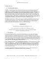
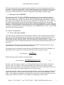
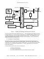
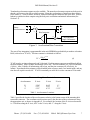
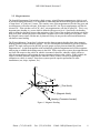
IMU-E604 Manual, Revision G, October 22, 2000
INERTIAL MEASUREMENT UNIT
OWNER'S MANUAL
PART NUMBER: IMU-E604
Revision G, October 21, 2000
WATSON INDUSTRIES, INC.
3041 MELBY ROAD
EAU CLAIRE, WI 54703
Phone: (715) 839-0628
FAX: (715) 839-8248
email: [email protected]
Web Site: www.primenet.com/~watgyro
Phone: (715) 839-0628
Fax: (715) 839-8248
EMail: Watson-Gyro.Com
IMU-E604 Manual, Revision G, October 22, 2000
Inertial Measurement Unit Manual
Table Of Contents
1.0 Introduction..........................................................................1
1.1
1.2
1.3
Production Description.................................................1
Installation...............................................................1
Microprocessor EEPROM.............................................2
2.0 Theory of Operation.................................................................2
2.1
2.2
2.3
2.4
2.5
2.6
2.7
2.8
2.9
2.10
Gyros and Angle Outputs..............................................2
Coordinate Transformations...........................................3
Error Limits and Extended Time Constants..........................5
Accelerometers..........................................................6
Magnetometers..........................................................8
Reference Outputs ......................................................10
Initialization..............................................................10
Coast Mode..............................................................10
Velocity Corrections....................................................11
Unslaved Heading......................................................11
3.0 Sensor Specifications...............................................................12
3.1
3.2
3.3
3.4
3.5
Angular Rate.............................................................12
Acceleration..............................................................12
Roll and Pitch ...........................................................12
Heading..................................................................13
Other Specifications ....................................................13
4.0 Output and Interface.................................................................13
4.1
4.2
4.3
4.4
Appendix A
Appendix B
Appendix C
Appendix D
Appendix E
Appendix F
Appendix G
Analog Outputs..........................................................13
Analog Inputs ...........................................................14
RS-232 Output Format.................................................15
RS-232 Input Commands..............................................17
Serial Command Summary..........................................19
Service Agreement and Warranty...................................23
Heading Calibration Program.......................................24
Data Recorder Program..............................................26
Velocity Calibration Program .......................................29
Binary Format.........................................................31
Outline and Pinout....................................................32
Watson Industries prides itself in solving customer problems and serving their needs in a timely
fashion. This manual facilitates this goal and provides written information about your product. We
ask that you carefully read this manual. Becoming familiar with the manual will help you understand
the product’s capabilities and limitations, and provide you with a basic understanding of its operation.
If, after reading the manual, you require further assistance, do not hesitate to call Watson Industries.
Phone: (715) 839-0628
Fax: (715) 839-8248
EMail: Watson-Gyro.Com
IMU-E604 Manual, Revision G
1.0 Introduction
1.1 Production Description
The IMU is a solid state gyro system which models the functions of an attitude gyro and a slaved
heading gyro. The angular rate sensor signals are coordinate transformed and then integrated to
produce attitude and heading outputs that reflect normal aircraft attitude coordinates. The attitude and
heading signal errors are calculated by comparing the attitude and heading with the two vertical
reference pendulums and a triaxial fluxgate magnetometer. These errors are filtered and are used to
adjust sensor biases so that the long-term convergence of the system is to the vertical references and
the magnetic heading. Compensations for centrifugal forces and velocity changes are used to improve
overall stability and accuracy. Note that the velocity input is an optional item. The velocity may be in
either the form of a forward velocity or a GPS velocity (East, North, Up velocity).
The sensors are interfaced to a 68HC11 microprocessor through a 16 bit analog to digital converter.
The analog outputs are from a 12 bit digital to analog converter (although the system’s angular rate
outputs are direct analog connections). An RS-232 serial connection is provided with all units.
Software is available in Macintosh and PC format for calibrating heading.
WARNINGS
Rough handling and high shocks will damage this unit.
Over-voltage and/or reverse voltage may cause damage to the unit.
The unit is gasket sealed but not water-tight. Protect the unit against prolonged
exposure to high humidity and/or water.
1.2 Installation
The base plate of the transducer is intended to be mounted on top of a horizontal surface with the
connectors toward the forward direction of the vehicle. A drawing is included at the end of this
manual. The unit may be adhesively mounted at any of its surfaces. If high shock loads are expected
(greater than 20 g's or repeated shocks greater than 2 g's), the appropriate shock mounting should be
used to prevent damage. If severe vibration is expected, some vibration mounting may be required. It
is very important to minimize vibration that has an angular component. The angular component will be
sensed by the rate gyros causing the outputs to appear noisy.
This is a magnetic device. Use non-magnetic hardware. Watson Industries provides brass
connectors with the device. Ideally, the unit should be installed at least 4” away from all magnetic
masses. If installing in a vehicle, ship, etc., some calibration is still required. Use the calibration
software provided with the unit. Please note that calibrating the heading sensor is important even if
you are only choosing to use pitch and roll outputs. Large errors in heading can cause significant
errors in all attitude outputs.
For shipboard applications, install the sensor near the center of gravity. For all applications, it is
preferable to install the device where linear dynamic effects are minimized.
Phone: (715) 839-0628
Fax: (715) 839-8248
EMail: [email protected]
1
IMU-E604 Manual, Revision G
This unit has an internal power regulator to allow operation over a wide voltage input range. Best
operation is obtained at approximately 12 VDC, although operation is fully satisfactory from 10 VDC
to 16 VDC. Current draw of the unit is about 600 mA. Internal filtering will remove a reasonable
level of power line noise; however, the user is responsible for providing a regulated supply.
1.3 Microprocessor EEPROM
The microprocessor has 512 bytes of EEPROM memory that are preserved even when power is
removed from the unit. The memory is used by Watson Industries to store calibration coefficients,
serial output information, and other operational values described throughout this manual. Many of
these values can be changed by the user to customize performance to requirements. These values can
be changed either through a Watson Industries supplied program or through use of any terminal
program. Commands for changing the first 256 bytes are described in Appendix A, Serial Command
Information. Watson Industries recommends that you save default EEPROM values before changing
any values. Watson Industries provides a printed copy of the EEPROM map as well as a copy on disk
with the Watson software programs.
2.0 Theory of Operation
2.1 Gyros and Angle Outputs
The Watson rate gyro and attitude system incorporates a balance of time constants and error limits to
reduce the effects of dynamic motion, and, at the same time, maintain responsiveness and accuracy .
The correction systems, which all attitude systems use, also allow errors from the forces on a
maneuvering aircraft to enter the system. The correction system is shown in Figure 1. Integral to the
correction system are the coordinate transformations used to translate information from body axes to
inertial axes.
The angular rate gyro outputs are compensated outputs which reflect the output of the gyro minus
estimated biases. These rate outputs are shown in Figure 1.
The angular system is essentially second order and each individual axis (Roll, Pitch, Heading), has
approximately (for a single axis of motion) the following La Place response to inputs:
Gyro Response =
K • Rate • s
s + 2ζω n + ω n
2
(1)
and the following general response to reference inputs:
K •Response•( G1 F • s • +ω n 2 )
Gyro Response =
s2 + 2ζω n + ω n 2
(2)
For those versed in frequency response, you will note that the output will eventually return to the
reference value. For example, a short-term bias change will cause the angle output to respond.
However, this will generate an error signal which will change the system to compensate for this bias.
Therefore, the system is self-compensating for errors in the rate sensor.
A disadvantage of the system is that errors in the angle reference will affect the angular rate and angle
output. For example, a lateral or forward acceleration will cause errors in the pendulum reference
signal. If these signals are significant compared to the system Time Constant, noticeable errors will
be generated. Please refer to Table 1 for a complete list of appropriate time constants.
Phone: (715) 839-0628
Fax: (715) 839-8248
EMail: [email protected]
2
IMU-E604 Manual, Revision G
Inertial Axes
Body Axes
+
-
Rate Gyros
^
Z
Velocity
G2
Acceleration
Corrections
^ ^ ^
X Y Z
Rate
Outputs
F/s
Roll and Pitch
Angle References
TriAxial Fluxgate
Magnetometer
C
o
o
r
d
i
n
a
t T
e r
a
n
s
f
o
r
m
Roll
Pitch
+
F/s
G3
Heading
G1
+
Reference Input
Heading
Calculation
Figure 1. Attitude and Heading Translation and Correction
The time constant is theoretically defined as the (δωn)-1. The time constant can be defined as the time
for approximately 63% of an error signal to be eliminated. Two EEPROM variables (TBM and TCN),
can change the damping coefficient and the undamped natural frequency. The EEPROM map can be
changed either through a Watson program or through a terminal program. The time constants and
damping coefficients are related in Table 1.
2.2 Coordinate Transformation
An essential concept to grasp is that the roll and pitch angles given by the unit are the angles for
direction cosine matrices (often referred to as Euler Angles). Direction cosine matrices relate vector
components in one coordinate frame to another coordinate frame. It is not the intention of this manual
to fully discuss or develop these transformations. For a fuller explanation, the user is advised to
pursue other references.
To fully define the attitude of the unit, one must know the
a) Direction Cosine Matrices
b) The order of the transforms
c) Specific coordinate frames between which these transforms operate.
Phone: (715) 839-0628
Fax: (715) 839-8248
EMail: [email protected]
3
IMU-E604 Manual, Revision G
For this unit, there are three primary coordinate systems of interest:
a) Body Axis Coordinates: These coordinates are defined by the physical unit itself and are
shown in the unit drawing at the rear of the manual (Appendix F). The positive XB Axis (See Figure
2) extends through the connector side of the unit. Note that the angular rate outputs are in the body
axis coordinate system.
b) Local Level Coordinate System: The local level coordinate system is defined by the
projection of the XB axis onto level. The resultant projection is XL (See Figure 2). The heading angle
is the angle between XL and North (XN).
c) Magnetic North Navigation Frame: This frame is defined by the Magnetic North direction.
The angle between XL and North (XN) is Ψ M.
Figure 2. Coordinate Systems
XB
Connector Forward
Magnetic North, XN
XB
ψ XB
m
YB
ZB
Body Axis
XL
East, YN
ZL,ZN
The order of the transformation from the magnetic North coordinate frame to the body axis frame is
heading, pitch, and then roll. Note that these rotations do not coincide with the body axis coordinates
of the unit, except for the roll axis. Each rotation is around these axes:
Angle
Coordinate Frame
Axis of Rotation
Heading
Pitch
Roll
Magnetic North
Local Level
Body Axis
ZN
YL
XB
Phone: (715) 839-0628
Fax: (715) 839-8248
EMail: [email protected]
4
IMU-E604 Manual, Revision G
The Magnetic North Frame to the Body Axis Frame rotations are as follows:
C
C
B
C
B
N
N
=
B
N
= CΦ C Θ CΨ
1
0
0
cosΦ
0
sin Φ
cosΘ
0
0
1
− sinΘ
0
cosΨ
− sinΨ
sin Ψ
cos Ψ
0
0
0
−sin Φ
cosΦ
sinΘ
0
cosΘ
0
0
1
CosΘCosΨ
CosΘSinΨ
= SinΦSinΘCosΨ − CosΦSinΨ SinΦSinΘSinΨ + CosΦCosΨ
CosΦSinΘCosΨ + SinΦSinΨ CosΦSinΘSinΨ − SinΦCosΨ
−SinΘ
SinΦCosΘ
CosΦCosΘ
where,
Φ
Θ
Ψ
Roll Angle
Pitch Angle
Heading Angle
These transformations are also used in calculating Magnetic Heading and calculating leveled
acceleration information (See Sections 2.4 and 2.5). For these transformations, the heading angle Ψ is
zero, thereby making the heading cosine angles 1 and the heading sine angles 0. Note that if you wish
to translate information from the body axes to level or magnetic North coordinates, you must use the
transpose of the matrix.
2.3 Error Limits and Extended Time Constants
The error signal (shown in Figure 1) is also used to enhance the performance of the angle and rate
system. The microprocessor continually compares the error signal to a level stored in EEPROM. This
level is individually set for roll, pitch, and heading. If the error signal exceeds the preset level, the unit
will change from its standard time constant (stored in EEPROM location B608), to an extended time
constant (stored in location B609). The time constant will also change to an extended time constant if
the roll or pitch exceeds 60°.
The error signal on a particular axis will be limited to the error signal level stored in EEPROM but only
for that axis. These locations and typical values are described in Table 2. There are individual error
flags in the output status bytes ( see Section 4.3) which show when these error limits have been
exceeded. An additional level of error limiting is available at the rate bias integrator. The change in
rate bias will be quite small except during initial turn on; therefore, the signal into the rate bias
integrator is clamped to a relatively small value (see Table 2).
Phone: (715) 839-0628
Fax: (715) 839-8248
EMail: [email protected]
5
IMU-E604 Manual, Revision G
TB
Damping Coefficient
*TCN2
Time Constant
-2.5
1.7
1.2
0.9
0.6
0
4
8
C
10
14
18
80
1.8
3.6
7.2
14.4
28.8
57.6
115.2
∞
0
1
2
3
4
5
Table 1. Time Constant and Damping Coefficient Values
*Note that the values are listed in hexadecimal.
When exceeding error levels, the extended time constant will remain in place until the error signal
condition is eliminated. When the error signal condition is eliminated, the time constant will begin
stepping down in accordance with the increments shown in Table 1. The rate at which the time
constant returns to normal is controlled by the value stored in location B60E. The time to return to the
standard time constant is determined by the following equation:
Time To Return =
256• Steps
TCR • 71.11
(3)
where 71.11 is the system sampling rate, TCR is the value time constant rate stored in location B60E,
and Steps is the difference in value between the normal time constant, and the extended time constant,
divided by 4 (see Table 1.). The one exception is where the extended time constant is set to 80H (see
Table 1) which causes an infinite time constant and is equivalent to the "Coast Mode" described in
Section 2.7.
EEPROM Location
B6E0
B6E2
B6E4
B6EC
Error Limit
Typical Value
Hexadecimal
Roll
Pitch
Heading
Rate Bias
10°
10°
10°
1°
071C
071C
071C
00A4
Table 2. Error Limit Locations and Values
2.4 Accelerometers
The accelerometer signals are corrected continuously with bias estimators linked to the pendulous angle
references. Angle references provide a low bandwidth reference which has excellent low frequency
acceleration performance. Figure 3 describes the method used to correct any bias errors in the
accelerometers. The accelerometers are also corrected by the microprocessor for scale and cross-axis.
Phone: (715) 839-0628
Fax: (715) 839-8248
EMail: [email protected]
6
IMU-E604 Manual, Revision G
Translated accelerometer outputs are also available. The normal accelerometer outputs are body-axis in
that they will rotate as the ship or vehicle rotates. Often, the accelerations of interest are those relative
to the earth (i.e., vertical, lateral, forward), with forward being the connector end of the unit. Watson
Industries synthesizes these outputs using the body axis acceleration and attitude information (See
Section 2.2).
X
Linear
Accelerometers
X
Y
+
Y
Z
-
Z
Bias Integrator
+
-
Roll and Pitch
Angle References
Figure 3. Acceleration Bias Correction
The rate of bias integration is programmable in the unit EEPROM map (double byte number at location
B648, referred to as TCAW). The time constant is calculated as follows:
TC =
128• 2TCAW
71.11
(4)
TCAW must be an integer between 0 and 24 decimal. Each increment represents an additional shift in
the bias estimator. After 18 shifts, information will be lost. The bias estimator is a 2 byte accumulator
(16 bits). After 24 shifts, all information will be lost, and the time constant will, effectively, be
infinite. Note that the bias estimator will be disabled in the reference mode, free inertial mode, and any
time the roll or pitch exceeds 60°. TCAW is nominally set at 00 04 for a time constant of 28 seconds.
Distance Along Coordinate Axis
Accelerometer
X Axis
Y Axis
Z Axis
X
Y
Z
-3.20"
-5.23"
-3.55"
0.69"
2.89"
0.79"
-1"
-1"
-2.32"
Table 3. Accelerometer Locations
Table 3 specifies the location of the accelerometers relative to the bottom center of the mounting hole
nearest the connector. The coordinate axis directions specify the direction of the accelerometer along
the appropriate axis, as shown in Appendix F. For example, the location of the X Axis accelerometer
is -3.20 inches along the X Axis, 0.69" in the Y Axis, and -1" along the Z Axis.
Phone: (715) 839-0628
Fax: (715) 839-8248
EMail: [email protected]
7
IMU-E604 Manual, Revision G
2.5 Magnetometers
The Inertial Measurement Unit includes a high accuracy triaxial fluxgate magnetometer which is used
to provide heading information. It is important to understand that the triaxial fluxgate magnetometer is
a “strap-down” or “body-axis” sensor. The sensitive axes of the magnetometer (like the rate gyros and
accelerometers) will rotate with unit. If the unit is elevated 20°, the X axis magnetometer will also be
elevated 20°. If the unit has a roll of 20°, the Y axis magnetometer will also be rolled 20°. This is very
important since heading is a vector which is defined with respect to level. Specifically, the heading
angle is defined as the angle between the projection of the X axis of the magnetic measuring unit on the
local level plane, and the projection of the Earth’s magnetic field vector on the local level plane. Since
the fluxgate sensors rotate with the unit, by themselves they do not provide sufficient information to
calculate accurate heading.
The Watson Industries "strap-down" solution provides better magnetic heading then other magnetic
heading products using mechanical gimbals. We use roll and pitch information to provide a software
gimbal. The angle sensors used in the IMU provide greater accuracy than mechanically gimbaled
magnetometers. A significant problem with mechanically gimbaled magnetometers becomes apparent
when trying to calibrate the heading sensor in the field. With a strap down system, the magnetometers
are fixed with respect to the vehicle in which it is mounted; therefore, when the vehicle pitches or
rolls, the magnetometers still maintain the same orientation relative to the vehicle. With a gimbal, the
vehicle will rotate about the magnetometer when the vehicle is tilted, effectively degrading any
calibration as vehicle is rotated. Strap down systems provide superior performance in most
installations (cars, ships, airplanes, etc.).
η
_
Z
_
Z
T
X E
Y
B
ζ
ψJ
D
ψm
ξ (True North)
_
H (Magnetic North)
Heading (Connector forward)
Figure 4. Magnetic Heading
Phone: (715) 839-0628
Fax: (715) 839-8248
EMail: [email protected]
8
IMU-E604 Manual, Revision G
The Earth’s Magnetic Field can be described as a Vector T located in the horizontal geographic
coordinate system Ozxh (See Figure 4).
Where:
H
Vector of Horizontal Component of Earth’s Magnetic Field
Z
Vector of Vertical Component of Earth’s Magnetic Field
J
Magnetic Dip Angle
D
Magnetic Declination
Ψm
Magnetic Heading
Ψ
True Heading
X,Y,Z
Sense Axes for Fluxgate Magnetometer Triad
E
Pitch - With Respect to Level.
B
Roll - With Respect to Level.
The microprocessor transforms the x, y, and z measurements to a horizontal geographical coordinate
system (local level, see Section 2.2, Coordinate Transforms) and calculates the respective components
of the Earth’s Magnetic Field, as follows:
H=
XT2 + YT2
(5)
Ψ = Tan−1 (XT YT )
where XT, YT, and ZT are coordinate transformed to the horizontal system for Fluxgate Magnetometer
measurement. To measure Magnetic Declination, the unit must either be turned to true North or its true
direction needs to be known.
Declination = Ψ − Ψm
(6)
If you are only interested in the variation of declination, you do not need to know True Heading.
Watson Industries provides software for calibrating heading in your installation. Your particular
installation will likely have significant magnetic deviations. Your location on the globe will also affect
your errors. Heading errors can be caused by magnetic biases, magnetic scale factors, and leveling
errors. The leveling errors are affected by the dip angle. The following is a general relationship:
∆ L = Tan(Dip Angle) • ( Heading Errors Due to Leveling )
(7)
Table 3 lists a general relationship between Dip Angle and Latitude.
Latitude
Dip Angle
30
45
45
60
56
68
70
80
80
85
Table 4. Dip Angle Versus Latitude
Phone: (715) 839-0628
Fax: (715) 839-8248
EMail: [email protected]
9
IMU-E604 Manual, Revision G
2.6 Reference Outputs
An alternate set of sensor information is available to the user. The standard set of data outputs
provides a close-loop integration of angular rate to the pendulous references, heading rate to the
magnetic heading sensor, and accelerometer biases to the accelerometers. Some users may prefer the
outputs without this integration. This is particularly useful if attitudes expected during instrumentation
are not known, since the unit can operate only for short periods of time at roll and pitch angles greater
than 60°. The reference command provides the same sensor information with the following differences:
Roll and Pitch are obtained directly from the pendulums;
Magnetic Heading is not gyro stabilized;
Angular Rate Sensors are not close-loop bias corrected;
Accelerometers are not close-loop bias corrected.
Translated accelerations are not valid during a reference mode, although the output is still available.
The output is equivalent to the body-axis accelerometers. The reference mode can be selected either
through the terminal mode (command “R”), or by using the hardware reference command (logic high
selects the reference command). Note that when using the serial command, this output mode is not
saved to EEPROM. It must be re-selected when re-powering the unit.
2.7 Initialization
The unit initializes during power up, during a commanded hardware initialization, or during a software
initialization request. During initialization, the unit should either be at rest or in a non-accelerated and
non-rotating state. During initialization, the unit estimates gyro and accelerometer (if installed) biases.
It also resets system time constants to the standard values. The time to initialization is stored in
location B60F. Each count in this location corresponds to a 0.9 second increase in initialization.
Watson Industries recommends that the initialization time be > 5 seconds. The default initialization
time is set to 10 seconds.
2.8 Coast Mode
The coast mode keeps all error signals (see Figure 1) at zero. In this mode, the angle outputs are
entirely unaffected by any accelerations. However, this mode also disables the processing
mechanisms which prevent drifts in output angles. The amount of drift is dependent upon the accuracy
of the rate bias estimation prior to entering the coast mode. If the unit is at rest for > 2 minutes, prior
to entering this mode, typical angle drift is < 0.4°/minute. Note that an "automatic" coast mode can be
set using the error limits and an infinite extended time constant. This is described in Section 2.3,
Table 1.
Phone: (715) 839-0628
Fax: (715) 839-8248
EMail: [email protected]
10
IMU-E604 Manual, Revision G
2.9 Velocity Corrections
Some users may place the unit in a high velocity environment where significant long-term accelerations
will act upon the unit. The unit takes a velocity input and calculates centrifugal force, using forward
velocity and turn rate. The unit will also differentiate the forward velocity to calculate a forward
acceleration. This can provide significant accuracy improvements during long term accelerations
(greater than 1/3 of the selected time constant). Two standard velocity options are available on the unit:
a) Forward Velocity Input - A forward velocity is inputted through the analog
connector. To use the velocity corrections, the user must either ground the invalid
velocity input or send an RS-232 valid velocity command. The unit takes the forward
velocity information and calculates centrifugal force and forward acceleration. This
approach neglects any vertical components of acceleration. Note that unless velocity is
enabled, either through the analog velocity enable pin or a serial command (see Section
4), the serial velocity output will be zero. When velocity is enabled, bit 4 of the flag
byte (See Section 4) is set.
A program is available to calibrate the analog velocity input. The
program is described in the appendices.
b) Watson Binary Format GPS Velocity Input - A triaxial velocity, relative to
Geographic North, East, and local vertical, is transmitted to the unit. The messages are
transmitted at a 2 Hz data rate. The data input is similar to the binary format described
in Appendix E except that the message has no carriage return. Instead, the first bit of
the first byte is set to zero and the remaining bytes have their first bit set to one. The
message consists of 3 two byte words. The full scale input of each word is ±400
KPH. The order of the input is North, East, and vertical velocity. With the vertical
velocity, "up" is positive.
When transmitting the binary format, the velocity enable pin must be grounded. When
grounded, the unit can only receive GPS data. All serial commands (described in
Section 4 and Appendix A) are invalid. In this mode, bit 4 of the flag byte (See Section
4) is set.
The GPS serial mode is selected by means of a setting in the EEPROM map. Location
B6F6 is specifically reserved for setting the mode of operation for the unit. If Bit 01H
is set (do not change the other bits) the unit will have the capability to receive serial
GPS information. If not set, velocity input is expected through the normal analog
velocity input pin.
Please contact Watson Industries for further information on other GPS interface options.
2.10 Unslaved Mode
In normal operation, the heading output is slaved to the compass output (See Figure 1). In some
applications, it may not be desirable or necessary to have a compass output. In addition, an
uncalibrated compass may cause accuracy problems which can translate into the roll and pitch outputs.
For this reason, some of our customers choose to buy units that do not have a compass or alternatively
to unslave the heading output from the compass. The result of doing so means that the heading output
is not magnetic and not relative to Magnetic North.
Phone: (715) 839-0628
Fax: (715) 839-8248
EMail: [email protected]
11
IMU-E604 Manual, Revision G
The unslaved mode is selected by means of a setting in the EEPROM map. Location B6F6 is
specifically reserved for setting the mode of operation for the unit. If Bit 40H is set (do not change the
other bits) the unit will be in unslaved mode. During unslaved mode, the heading will have the
following value.
If the Z Axis Rate < Zlim, Heading(N) = Heading(N-1)
If the Z Axis Rate > Zlim, Heading(N) = Heading(N-1) + Turn_Rate(N)/Frame_Rate
Where N indicates the frame, the angular rates are in degrees per second and heading is in degrees.
The value Zlim is stored in the EEPROM at value B6EA. It is in two's complement format and it's full
scale value is the same as the binary output full scale (see Section 4.3).
3.0 Sensor Specifications
3.1 Angular Rate
Analog
Range
Bias*
Resolution
Bandwidth
Scale Factor
Digital
±100°/Second
±100°/Second
< 0.1°/Second
< 0.1°/Second
< 0.02°/Second
.024°/Second
> 70 Hz
20 Hz
-1% to + 5% Over Temperature
*In reference mode, the bias will change by no more than ±2°/second over the specified temperature range.
3.2 Acceleration
Analog
Range
Scale Factor Accuracy
Bias
Resolution
Frequency Response
±2 g's
> 1% of F.S.
< 20 mG's
1 mG
20 Hz
Digital
±2 g's
> 1% of F.S.
< 10 mG's
0.25 mG's
20 Hz
3.3 Roll and Pitch
Resolution
Range
Accuracy
Frequency Response
Analog
Digital
0.09°
0.03°
±60° Static, ±180° Dynamic
0.2° to 20°, 1% F.S. Static to 60°
DC-20 Hz (DC-12 Hz, Reference Mode)
The pendulum references only provide an angle reference to 60°. Beyond this angle, the unit will
integrate the gyros in a mode similar to the coast mode (see Section 2.7).
Phone: (715) 839-0628
Fax: (715) 839-8248
EMail: [email protected]
12
IMU-E604 Manual, Revision G
3.4
Heading
Analog
Resolution
Accuracy
Repeatability
Digital
0.09°
0.03°
±3° to 30 Degrees Angle*
Better Than 0.5°, Analog and Digital
Analog Scale: 0-360° (18°/Volt), South = ±10 VDC, West = -5 VDC, North = 0 VDC, East = +5 VDC
*Accuracy of the unit is greatly dependent upon field calibration. Even with perfect calibrations, field variations in the
magnetic declination will affect accuracy.
3.5 Other Specifications
Power Requirement
+12 VDC, < 600 mA
Size
See Drawing, Appendix F
Weight
< 4 Pounds
Shock (Survival)
600 g's
Temperature Range
Operating:
Survival:
-30°C to +71°C
-40°C to +85°C
4.0 Output and Interface
The IMU has both an analog and a digital interface. To prevent hardware/software conflicts, all analog
switches are disabled when the following RS-232 commands are sent to the unit.
Reference Command
Velocity Command
Coast Mode Command
4.1 Analog Outputs
The analog outputs have a full scale range of ±10 VDC and come from a 12 bit digital to analog
converter. The following outputs are available. Their full scale ranges are listed in the second column.
Roll*
Pitch*
Heading*
X Acceleration
Y Acceleration
Z Acceleration
Forward Acceleration
Lateral Acceleration
Vertical Acceleration
X Rate
Y Rate
Z Rate
Phone: (715) 839-0628
±180°
±180°
±180° (North = 0 VDC)
±2 g’s
±2 g’s
±2 g’s
±2 g’s
±2 g’s
±2 g’s
±100°/sec
±100°/sec
±100°/sec
Fax: (715) 839-8248
EMail: [email protected]
13
IMU-E604 Manual, Revision G
The outputs have a 300 Ω source impedance. The roll, pitch, and heading outputs may be amplified
by setting the appropriate EEPROM location. The analog outputs are amplified muliplied by 2 for each
count. However, the first byte of the location is ignored.
B65E
B66E
B67E
Amplify Roll Analog Signal
Amplify Pitch Analog Signal
Amplify Heading Analog Signal
For example, if location B65E were set to "00 02", the roll analog signal would be amplified by 4
(22).
4.2 Analog Inputs
The IMU allows the user to input analog data that can then be added to the serial data output. This
allows the system to act as a data acquisition unit for other vehicle information such as engine RPM,
engine temperature, fuel remaining, altitude/depth or any other data of importance. The four analog
user inputs and the velocity input have the following characteristics:
a)
b)
c)
d)
1 MΩ Input Impedance
Sixteen Bit Conversion Resolution
Input Range of ±10 volts (Beyond +15 VDC will Damage the Inputs)
Sampled at 71.11 Hertz
The IMU also has several analog digital inputs which are all activated by grounding. The user should
only apply a ground because all the inputs have a pull-up resistor to +5 VDC. The pins are as follows:
a) Initialization. Resets all integrators and error accumulators. The unit should be in a nonaccelerated condition if this command is given. Leave pin open if not in use. Ground to command.
Further information is in Section 2.6.
b) Reference. An alternate set of sensor information primarily intended as an instrumentation
mode. Leave pin open if not in use. Ground to command. Further information is in Section 2.5.
c) Coast Mode. Disables the bias accumulators for the rate gyros and the accelerometers.
Leave pin open if not in use. Ground to command.
d) Velocity Enable. See Figure 1. This pin will enable use the use of velocity compensations.
Velocity compensations are an option, not in a standard unit. Leave pin open if not in use. Ground to
enable velocity.
Phone: (715) 839-0628
Fax: (715) 839-8248
EMail: [email protected]
14
IMU-E604 Manual, Revision G
4.3 RS-232 Output Format
The RS-232 output format is factory set at 9600 baud, 1 stop bit, no parity bit. The user may also
select other baud rates including 4800, 9600, 19200, and 38400 baud. See Appendix A for more
details on selecting the baud rate.
The following table shows outputs available via the RS-232 serial link. The middle column shows the
exact format of the decimal output. A space is sent after the data (except for the last data in the string
which is followed by a carriage return). The decimal string starts with the letter "I" or "R" indicating
whether the unit is in reference or inertial mode (see Section 2.6). The letter may change to smaller
case ("i" or "r") if the unit is using an extended time constant (see Section 2.3). The sensor full scale
ranges are listed in the third column. The binary format is described in Appendix F.
Inertial Output
Roll
Pitch
Magnetic Heading
X Acceleration
Y Acceleration
Z Acceleration
Forward Acceleration
Lateral Acceleration
Vertical Acceleration
X Rate
Y Rate
Z Rate
Heading Rate
X Magnetometer
Y Magnetometer
Z Magnetometer
Roll Pendulum
Pitch Pendulum
User Channel 1
User Channel 2
User Channel 3
User Channel 4
Velocity
Internal Temperature
Status Bits
Flag Bits
Full Scale Decimal
±180.0°
±90.0°
0-360.0°
±2.00 g’s
±2.00 g’s
±2.00 g’s
±2.00 g’s
±2.00 g’s
±2.00 g’s
±99.9°/second
±99.9°/second
±99.9°/second
±99.9°/second
±999.9 mGauss
±999.9 mGauss
±999.9 mGauss
±180.0°
±90.0°
±9.99 VDC
±9.99 VDC
±9.99 VDC
±9.99 VDC
±400.0 Km/Hour
-40 to +88°C
3 Bytes
3 Bytes
Full Scale Binary
±180°
±180°
±180°
±2.00 g’s
±2.00 g’s
±2.00 g’s
±2.00 g’s
±2.00 g’s
±2.00 g’s
±200°/second
±200°/second
±200°/second
±200°/second
± 1000 mGauss
± 1000 mGauss
± 1000 mGauss
±180°
±180°
±10 VDC
±10 VDC
±10 VDC
±10 VDC
±800 Km/Hour
-40 to +88°C*
1 Byte*
1 Byte*
*In the binary format, these data words are only one byte in length. All other words are two bytes.
Phone: (715) 839-0628
Fax: (715) 839-8248
EMail: [email protected]
15
IMU-E604 Manual, Revision G
The Flag Bits contains the following information:
a) Bits 0-2 show the current system time constant, using the following equations:
TC=2(Flag Value + 1)
b) Bit 3
c) Bit 4
d) Bit 5
e) Bit 6
If set, reference command selected.
If set, velocity is valid.
If set, coast mode is selected.
If set, the analog switches are disabled.
The status bits contain the following information.
a) Bit 0
Roll Error Flag - Set if roll error exceeds limits (see Section 2.3).
b) Bit 1
Pitch Error Flag - Set if pitch error exceeds limits (see Section 2.3).
c) Bit 2Heading Error Flag - Set if heading error exceeds limits (see Section 2.3).
d) Bit 3
General Overrange Flag - Set when roll or pitch exceeds 60 degrees.
e) Bit 4Velocity Error Flag. Set if overrange on velocity compensation calculations
occurred. Also set if velocity input is not valid.
f) Bit 5Not used.
g) Bit 6
Checksum Flag - If set EEPROM is corrected or checksum value (located at the
end of EEPROM listing), was not reset after EEPROM was changed.
In the binary mode, the status bytes are decoded as read.
In the decimal mode, the number will be received in Octal. This appears on the terminal as a 3 digit
number. To decode, take each digit and convert to binary, resulting in a 7 bit binary number.
The user is allowed to select channels for output via the RS-232 link. Simply send “&” command and
respond to the menu selections. During initialization, a text header is sent by the unit that identifies the
unit both by part number and serial number and also gives the date of last calibration. This message
can be temporarily or permanently suppressed or restored by a “*” command from the interfacing
computer.
Note: You must follow a special initialization procedure to change output formats and allow keyboard
input*. This procedure has been a source of frustration to a number of our customers. We apologize
in advance but ask you to carefully follow our instructions.
1) Use a terminal program to observe communications with our unit. The format is
9600 baud, 8 bits, 1 stop bit, no parity bit. Initially, it is sometimes useful to select the
option to add a line feed to an incoming carriage return. Make sure that you have
selected the appropriate communications port. If you are unsure as to whether you are
receiving communications, it is helpful to hook up an oscilloscope to our transmission
line. The normal default ouput of the unit is text and observable on the screen.
2) Send a “!” followed by a space bar. This will cause the unit to initialize. When the
"!" is sent, data will stop flowing across the screen. After sending the space, you
should see the text header describing the program (unless disabled).
Phone: (715) 839-0628
Fax: (715) 839-8248
EMail: [email protected]
16
IMU-E604 Manual, Revision G
3) Hit the space bar twice (no more, no less), during initialization (after you see the
text header). The initialization last about 10 seconds or as defined in the EEPROM (See
Section 2.7). Normally, you should wait until you see data flowing (if data output is
not suppressed) across the screen before typing any additional space bars, characters
etc. After you wait through the initialization, type a "?" and you should be rewarded by
the sight of the EEPROM map flowing across your screen. Hitting a carriage return
will get the data flowing again.
*An alternative method is to run any of the calibration or data acquistion programs supplied with the
unit. After exiting these programs, enter your terminal program. You will find the serial commands
enabled.
Data transmission, sent by the unit, can also be suppressed or restored by a “+” command from the
interfacing computer. It can be permanently suppressed by sending a ":" command.
To select a binary format, send a “^” to the unit. To select a decimal format, send a “_” to the unit.
The decimal output is described below. The binary output is described in Appendix F.
The RS-232 decimal output consists of a string of decimal ASCII characters sent asynchronously. The
speed of transmission is dependent upon the amount of data selected for transmission. A string is sent
at 9600 baud with eight data bits, one stop bit and no parity. The speed can be roughly calculated by
dividing the number of bits per string into 9600 baud. Note that each byte uses 9 bits since the stop bit
is also included.
The format of the string is as listed in the decimal output column in the previous section. A single letter
and a space are used to indicate the start of the data string. The letter “I” indicates the start of an
inertial data string. The letter “R” indicates the start of a reference data string. If the letter is in lower
case, an error over range condition is indicated. All data items are separated by a space.
The serial output data rate is affected by a number of factors including the baud rate, the system
frequency of the unit, the amount of data selected by the user, and the format of the data. In addition,
it takes time for the microprocessor to respond to interrupt requests to send RS-232 data. The
following table summarizes the data rate for 9600 baud and a system frequency of 71.11 Hz.
#Bytes
2-18
19-25
32-40
41-46
47-56
Data Rate
71.11 Hz
71.11 Hz to 35.55 Hz
35.55 Hz
35.55 Hz to 17.78 Hz
17.78 Hz
With some numbers of bytes, the data rate is not an exact multiple of the system frequency. This is
due to variability in total microprocessor software load. The user is strongly encourage to test his
input rate if this is a critical factor.
4.4 RS-232 Input Commands
The RS-232 input commands are provided for the purpose of unit test and installation set-up. The
same parameters are used as for the output (9600 baud ASCII nominal, or as reset in the unit’s
EEPROM). Appendix A contains a summary of the commands.
Phone: (715) 839-0628
Fax: (715) 839-8248
EMail: [email protected]
17
IMU-E604 Manual, Revision G
Dear User
Please use this space for notes. If you have a suggestion for improving the manual, write it below and
fax it to us (715) 839-8248.
_________________________________________________________________________________
Phone: (715) 839-0628
Fax: (715) 839-8248
EMail: [email protected]
18
IMU-E604 Manual, Revision G
Appendix A
Serial Command Summary
A.0 Summary of Commands
The following commands are available but only following initialization with a double space bar. The
first space bar must be within 1 second following the exclamation mark. The next two space bars must
be after the initialization header (if selected) but before start up of data. We suggest waiting 2 seconds
after sending the "!" and <space>.
"!" <space>
“!”<space><space><space>
"I" or "i"
"R" or "r"
"F" or "f"
"K" or "k"
"C" or "c"
"V" or "v"
"^"
"_"
"~"
"?"
"@"
"("
"#"
"$"
"""
"&"
"*"
"+"
":"
">"
"{"
"}"
Reinitialize
Reinitialize and allow command mode.
Normal Operating mode. Hard wire switches are disabled.
Put Reference Command. Hard wire switches are disabled.
Free Mode. Hard wire switches are disabled.
Clear all Mode Commands, Disable Wire Input
Velocity Invalid Command. Hard wire switches are disabled.
Velocity Valid Command (Sending a "V", enables).
Set to Binary Output
Set to Decimal Output
Read RAM From 0000 TO 00FF
Read EEPROM From B600 TO B6FF
Replace one word of the EEPROM.
Load multiple bytes to the EEPROM
Add to one word ""
Subtract from one word of the EEPROM.
All current modes set are saved on EEPROM.
Select data for output.
Enable/Disable Initialization Message
Toggle RS-232 Output
Toggle RS-232 on Request
Set Current Output Channels (See Below)
Write any RAM or EEPROM Location (Consult Factory)
Read any RAM or EEPROM location (Consult Factory)
The changes in output format (binary, decimal), selected channels, are temporary until a single
quotation mark (") is sent.
Phone: (715) 839-0628
Fax: (715) 839-8248
EMail: [email protected]
19
IMU-E604 Manual, Revision G
A.1 Changing Output Data
In command mode, the serial outputs can be changed using the "&" command. The unit will respond
with a menu which looks as following:
TYPE IN THE NUMBER OF YOUR SELECTION (OR 'Q' TO QUIT):
1 = ADJUST TIME CONSTANTS
2 = SET OUTPUT CHANNELS
3 = LIST CURRENT OUTPUT CHANNEL SELECTION
4 = SET NEW BAUD RATE
The user will be prompted through each command. The adjustment of the baud rate is immediate but
is not saved to EEPROM. In other words, if you cycle power on the unit, it will not have the newly
selected baud rate. To make the change permanent, establish terminal communications at the new baud
rate, and then send a quotation mark -"- to make the change permanent. This procedure serves an
important function in that you must establish communications at the new baud rate in order for the
change to become permanent.
The setting of the output channels is through a menu. The user can answer "N", "Y", or "Q" to each
selection (upper or lower case is not important). If the user answers "Q", the items already selected
will be still be valid. The user will then be prompted with the following menu:
Y = GO BACK, N = INSTALL DATA & QUIT, Q = QUIT
DO YOU WANT TO TRY TO SET DATA AGAIN?
You must type "N" if you want the outputs changed. Type "Q" if you want to go back to the menu.
Type "Y" if you wish to return to selecting channels. In addition, if you want your selection to be a
default power up setting, you must send a double quotation mark """.
The serial outputs can be changed at all times using the ">" command. Upon sending the command,
the user should send a 8 byte ASCII hexadecimal number representing the four possible user pages.
The default user page values are stored in 4 bytes stored in EEPROM location B6F2. The ">"
command does not change the default until a quotation mark is sent. This can only be done in the
command mode allowed by the "! <Space> <Space> <Space>" command which is described in the
main body of the user manual.
When sending the ">" command, the following sequence will occur:
1) User sends ">" command.
2) Unit stops communications and sends a carriage return and line feed.
3) User sends to hexadecimal numbers, values between "00" and "FF." Unit echoes back
each character.
4) Unit send space indicating data received for particular user page.
5) Steps 3 and 4 are repeated for user pages 2,3, and 4.
6) Communications are resumed.
The user should send characters at a minimum interval of 100 milliseconds.
Phone: (715) 839-0628
Fax: (715) 839-8248
EMail: [email protected]
20
IMU-E604 Manual, Revision G
The user pages are organized as follows:
Page 1
80H = Roll
40H = Pitch
20H = Heading
10H = X Acceleration
08H = Y Acceleration
04H = Z Acceleration
02H = Forward Acceleration
01H = Lateral Acceleration
Page 2
80H = Vertical Acceleration
40H = X Axis Angular Rate
20H = Y Axis Angular Rate
10H = Z Axis Angular Rate
08H = Heading Angular Rate
04H = X Axis Magnetometer
02H = Y Axis Magnetometer
01H = Z Axis Magnetometer
Page 3
80H = X Inclinometer
40H = Y Inclinometer
20H = User Channel 1
10H = User Channel 2
08H = User Channel 3
04H = User Channel 4
02H = Forward Velocity Input or GPS East North Velocity
01H = Temperature
Page 4
80 = Status Word
40 = Status Word
20 = GPS East Velocity
10 = GPS Vertical Velocity
08 = Spare
04 = Spare
02 = Spare
01 = Spare
Phone: (715) 839-0628
Fax: (715) 839-8248
EMail: [email protected]
21
IMU-E604 Manual, Revision G
A.2 Reading/Writing EEPROM Locations
The commands for writing EEPROM locations must occur during command mode. These commands
allow access to EEPROM locations B600 to B6FF. A map listing can be obtained via terminal mode
by using the "?" command. The user can change locations by using the "@" command, subtract from
them using the "$" command, and add to them using the "#" command. In each instant, the following
command sequence will occur.
a) The unit stops sending communications
b) The units sends a carriage return, line feed, and the message "B6".
c) The user must then send a two byte address, ranging from "00" to "FF." Only even
addresses are valid (i.e., 02H, 04H, etc.).
d) The unit will send a single space, a "-", and then another space.
e) The user must send a two byte hexadecimal value, ranging from "00" to "FF."
f) The unit will echo back these values and send a space.
g) The user must send an additional two byte hexadecimal value, ranging from "00" to "FF."
h) The unit will echo back these values and then send a carriage return and line feed.
g) The unit will continue communications after being sent any additional character. If you
send a character which is a command, the unit will proceed with that command.
If you are sending the values using a computer program, we recommend a 100 millisecond interval.
Phone: (715) 839-0628
Fax: (715) 839-8248
EMail: [email protected]
22
IMU-E604 Manual, Revision G
Appendix B
DISCLAIMER
The information contained in this manual is believed to be accurate and reliable; however, it is the
user's responsibility to test and to determine whether a Watson Industries' product is suitable for a
particular use. Suggestion of uses should not be taken as inducements to infringe upon any patents.
WARRANTY
Watson Industries, Inc. warrants, to the original purchaser, this product to be free from defective
material or workmanship for a period of one full year from the date of purchase. Watson Industries'
liability under this warranty is limited to repairing or replacing, at Watson Industries' sole discretion,
the defective product when returned to the factory, shipping charges prepaid, within one full year from
the date of purchase. The warranty described in this paragraph shall be in lieu of any other warranty,
express or implied, including but not limited to any implied warranty of merchantability or fitness for a
particular purpose.
Excluded from any warranty given by Watson Industries are products that have been subject to abuse,
misuse, damage or accident; that have been connected, installed or adjusted contrary to the instructions
furnished by seller; or that have been repaired by persons not authorized by Watson Industries.
Watson Industries reserves the right to discontinue models, to change specifications, price or design of
this product at any time without notice and without incurring any obligation whatsoever.
The purchaser agrees to assume all liabilities for any damages and/or bodily injury which may result
from the use, or misuse, of this product by the purchaser, his employees or agents. The purchaser
further agrees that seller shall not be liable in any way for consequential damages resulting from the
use of this product.
No agent or representative of Watson Industries is authorized to assume, and Watson Industries will
not be bound by any other obligation or representation made in connection with the sale and/or
purchase of this product.
SERVICE
Watson Industries, Inc. has no service outlets. All service is performed at the factory. In order to
insure prompt service, prior to returning a unit for repair please call, write or fax:
Watson Industries, Inc.
3041 Melby Road
Eau Claire, WI 54703
ATTN: Service Department
Telephone: (800) ABC-GYRO or (715) 839-0628
Fax: (715) 839-8248
All sensors returned under warranty will be repaired (or replaced at the sole option of Watson
Industries) at no cost to the customer other than shipping charge from customer to Watson Industries
(plus any export and transportation charges outside the United States). In the case of units not under
warranty, a flat repair fee will be charged. This fee can be determined by contacting Watson
Industries.
Phone: (715) 839-0628
Fax: (715) 839-8248
EMail: [email protected]
23
IMU-E604 Manual, Revision G
Appendix C
Watson Heading Calibration Program
Installation
Insert the disk into drive A (assuming that this is your drive) and select Run from the File menu in
Windows. Type "A:\Setup" and select "OK". Do not have other programs running while you are
installing. This program requires Microsoft Windows 3.1 or later.
The program requires the Comm1 or Comm2 port to be available. You may switch to Comm2 after
running the program. If the Comm1 port is already in use (for example by a Mouse), the program will
not start. You can also use the port selection menu to reinitialize the unit if it was not powered prior to
entering the program, or if the unit was shut off during operation of the program. You may also
change the start up port by editing the first line of the “Sensor.Prf” file that is supplied with the
program.
Before running the program, connect the unit to your communications port. Power the unit and then
run the program. Data will appear in the windows at the top of the page. If no data has appeared,
select Port 2 from the communications menu. If no data appears, technical support is available at (800)
ABC-GYRO. Note that the “Unit Ready” indication in the text window is an indication that the laptop
has completed sending all information. At that time, data should appear in the data windows.
Mode of Operation
The unit can be calibrated in a gyro-stabilized (inertial) or non-stabilized (reference) mode. The
reference mode provides the highest accuracy if you are in a static situation. The inertial mode should
be used if you are calibrating the unit at sea, in the air, or any situation where the unit is moving. In
any case, it is advisable to minimize the amount of dynamics during calibration.
We recommend that the unit be reasonably close to level. The heading unit is able to measure its pitch
and roll angle. However, at large angles (> 10°), you may begin to observe a degradation in
calibration accuracy.
Point the unit in the direction of North, South, East, or West. You should be within ±20° of the
particular compass direction (but closer is better!). Record either by clicking on the "Enter Data"
button or by clicking in appropriate heading window. The Data Button can be accessed by pressing
the ALT and “E” key at the same time. After recording data in all 4 directions, the EEPROM button
will be enabled, and a message will appear in the instructions window. The instructions will give a
“Calibration Quality Factor” which is roughly equivalent, with large errors, to the average heading
error, in degrees. The instructions will also indicate how many more calibration iterations may be
required. Select the EEPROM button to send calibrations to the unit. If the user environment has large
offsets, several iterations may be necessary. At any point in the calibration, you may clear data or
enter a point that had been previously recorded.
Phone: (715) 839-0628
Fax: (715) 839-8248
EMail: [email protected]
24
IMU-E604 Manual, Revision G
Declination Button
The difference between true north and local magnetic north is referred to as variation (also known as
declination), and varies with both time and geographical location. Corrective values are routine
provided in the form of variation or declination tables printed directly on the maps or charts for any
given location. Use the declination button to enter the declination for the local area. When selecting
this option, keep in mind that this option is only intended for small offsets. The maximum allowable
offset is ±45°. Note: During calibration, this value should be returned to zero.
Memory Locations
This command allows you to view or change some of the memory locations discussed in this manual.
Please use this command with care. Indiscriminate use of this command can cause improper
operation, and if you have really bad luck, will require Watson Industries to open the unit and
reinitialize the EEPROM. Instructions are given when selecting the read or write memory command.
To read a memory location, you must have a 4 byte hexadecimal address. A number of these
addresses are given throughout the manual. We strongly recommend that you store a copy of your
EEPROM map before changing locations.
Dip Angle
The dip angle is defined as the angle between the local level plane and the magnetic vector. This
information is necessary for calibration. Table 3 in the manual lists Dip Angle for various latitudes. If
you need further assistance in determining your Dip Angle, contact Watson Industries. After
calibration, the unit does not depend upon this information.
User Support
Call Watson Industries, Inc., at the number and location listed below, or send an E-Mail message to
[email protected].
Phone: (715) 839-0628
Fax: (715) 839-8248
EMail: [email protected]
25
IMU-E604 Manual, Revision G
Appendix D
Watson Data Recorder
1.1 Introduction
This software provides the capability to graph and record data, and to visually display data. The
software requires Windows 3.1, Windows 3.11, or Windows 95, to run. These instructions are valid
for either the visual or decimal display programs. Files saved under one program may be used in the
other.
1.2 Software Installation
Insert the installation disk into drive A (assuming that this is your drive) and select Run from the File
menu in Windows. Type "A:\Setup" and select "OK". For Windows 95, select the Settings, Control
Panel, and then the icon for Adding/Removing programs. Do not have other programs running while
you are installing.
1.3 Hardware Installation
Serial connections are diagrammed in the manual for the unit. The program selects Comm1 as a
default setting. The default setting can be changed by modifying the "Sensor.prf" file (See Section
1.3). Connect the unit to the appropriate serial connector (usually a male 9 Pin D-Sub), on your
computer. Power the unit before starting the program. The software will automatically configure the
unit upon power-up. Note that many communication programs may require a CTS or DTS signal.
The standard 9 pin serial connector, on Watson units, has pins 4 and 6 shorted, and pins 7 and 8
shorted. This will accomplish the hardware handshake.
1.4 Installation Files
The installation disk has a number of installation files. The Watson program uses two initialization
files to record information. The "Watson.Prf" file stores all graph option data. It is not recommended
that the user edit this file. The "Sensor.Prf" file contains information about sensors installed, scale
factors, and the particular unit part number. The order of the file is as follows:
Line 1
Line 2
Line 3
Line 4
Line 5
Line 6
Line 7
Line 8
Line 9
Line 10
Line 10
Line 11
Line 12
Line 13
Phone: (715) 839-0628
Acceleration Binary F.S.
Roll Angle Binary F.S.
Pitch Angle Binary F.S.
Rate Angle Binary F.S.
Velocity Binary F.S.
Temperature Range
Timer Scaler
Magnetometer F.S.
Heading Binary F.S.
User Channel Binary F.S.
Default Communications Port
Unit Type
User Type
End of File Marker
Fax: (715) 839-8248
2 g's
180°
180°
200°/Second
800 KPH
120°
66.67
1000 millGauss
180°
10 VDC
1
Product Specific
"Customer"
"END OF FILE"
EMail: [email protected]
26
IMU-E604 Manual, Revision G
The Temperature Range, Line 6, is not currently implemented. The rate angle full scale output is only
100°/second. The 200°/second allows for over range processing. The Timer Scaler is an empirical
value used to estimate the time frame for binary data. The User Channel Binary F.S. can be adjusted
to scale the output for the particular user input. The default communications ports can be changed to
"2" if the user prefers Comm Port 2. In either case, the port is selectable during the program. The
Unit Type is generally either "IMU", "DMS", "AHRS", or "HEADING". Although the customer may
edit the Sensor.Prf file, it is essential that the proper number of lines be maintained.
2.0 Watson Data Recorder
2.1 Operation
VCR Controls - The Watson Data Recorder can provide an efficient and quick tool for data
recording, graphing, and printing. The unit functions as a VCR with a RECORD and PLAYBACK
mode. In the record mode, data is being recorded for playback or graphing. When recording, the
current time will be incrementing while the total time remains static. The GRAPH button will also be
greyed when data is being recorded. When you enter the PLAYBACK mode, the total time will
indicate total test time recorded and the current time will indicate which data, in that time period, is
being displayed. At this point, you may play the data, fast forward, pause, or rewind. At this point,
the graph data also becomes available.
Saving Data - To save your data, simply select Save or Save As from the File Menu. Note that the
Save command will only prompt you once for a name. After that, it will simply overwrite the file
name previously selected. The Save as Text option saves data in an integer format. This can be used
in your own graph package. Full scale limits for the integer data are described in the user manual for
the unit.
Adjusting Time - The recorder will only save a maximum of 225 seconds of data. The user can
adjust the time by clicking on the box to the left of the "Time" box, below the VCR controls. The user
will then be asked to input a test time. The program will automatically stop at the completion of test
time. If the test time is set at maximum, if you select 225 seconds or greater, default will be set at 225
seconds. When at the maximum value, the program will not automatically stop but will "roll over" and
restart at zero test time.
2.2 Menu Options
The following describes the menu options available.
Port - This menu option allows you to change the communications port. "1" Corresponds to Comm
Port 1, and "2" corresponds to Comm Port 2. Selecting the port also causes the computer to set up the
unit for communications. If the unit is not connected prior to running the program, it may not be
properly configured. Sending the Port 1 or Port 2 command will properly initialize the unit.
If you wish to change the default port, see Section 1.4.
Commands - These menu commands are equivalent to the hardware and serial commands described
in the user manual for the particular unit.
Graph Options - A graph options window will appear. This window controls which sensors are
graphed. The user must select at least one sensor. The user can let the program autoscale all axes by
checking the box in the lower left hand corner. If the box is not checked, individual minimums or
maximums, or auto scale selections, are observed for that sensor.
Phone: (715) 839-0628
Fax: (715) 839-8248
EMail: [email protected]
27
IMU-E604 Manual, Revision G
Memory - Allows the user to view and change the contents of a 68HC11 EEPROM location on the
68HC11. As described in the hardware user's manual, the EEPROM holds information for
configuring and calibrating the unit. Memory locations are available from B600 to B7FF
(hexadecimal), but only even numbered memory locations are valid addresses. To read a memory
location, do the following:
1. Select Memory then Read.
2. In response to the input box, type a valid four letter address (for example, B600).
3. The contents of the two byte memory location will appear in a message box.
To write to a memory location:
1. Select Memory then Write.
2. In response to the input box, type a valid 8 letter address (for example, B6007FFF).
Note that indiscriminate use of the write command can degrade performance. Before changing
memory, we recommend that you save a copy of the EEPROM map using the calibration save option
in the heading calibration program.
Phone: (715) 839-0628
Fax: (715) 839-8248
EMail: [email protected]
28
IMU-E604 Manual, Revision G
Appendix E
Velocity Calibration Program
Installation
Insert the disk into drive A (assuming that this is your drive) and select Run from the File menu in
Windows. Type "A:\Setup" and select "OK". Do not have other programs running while you are
installing. This program requires Microsoft Windows 3.1 or later.
The program requires the Comm1 or Comm2 port to be available. You may switch to Comm2 after
running the program. If the Comm1 port is already in use (for example by a Mouse), the program will
not start. You can also use the port selection menu to reinitialize the unit if it was not powered prior to
entering the program, or if the unit was shut off during operation of the program. You may also
change the start up port by editing the first line of the “Sensor.Prf” file that is supplied with the
program.
Before running the program, connect the unit to your communications port. Power the unit and then
run the program. Data will appear in the windows at the top of the page. If no data has appeared,
select Port 2 from the communications menu. If no data appears, technical support is available by
calling Watson Industries at (715) 839-0628.
Menu Descriptions
File - Exit program.
Comm - This menu option allows you to change the communications port. A "1" corresponds to
Comm Port 1, and a "2" corresponds to Comm Port 2. Selecting the port also causes the computer to
set up the unit for communications. If the unit is not connected prior to running the program, it may
not be properly configured. Sending the Port 1 or Port 2 command will properly initialize the unit.
If you wish to change the default port, edit the Sensor.Prf file. Change Line 11 of the Sensor.Prf file
(located in the same directory as the executable program) from a "1" to a "2".
Calibrations - This menu option allows you to save previous calibrations and then to reload these
calibrations at a later date. We recommend that you save factory calibrations before recalibrating the
velocity input.
EEPROM - Allows the user to view and change the contents of a 68HC11 EEPROM location on the
68HC11. As described in the hardware user's manual, the EEPROM holds information for
configuring and calibrating the unit. Memory locations are available from B600 to B7FF
(hexadecimal), but only even numbered memory locations are valid addresses. To read a memory
location, do the following:
1. Select Memory then Read.
2. In response to the input box, type a valid four letter address (for example, B600).
3. The contents of the two byte memory location will appear in a message box.
Phone: (715) 839-0628
Fax: (715) 839-8248
EMail: [email protected]
29
IMU-E604 Manual, Revision G
To write to a memory location:
1. Select Memory then Write.
2. In response to the input box, type a valid 8 letter address (for example, B6007FFF).
Note: Indiscriminate use of the write command can degrade performance. Before changing memory,
we recommend that you save a copy of the EEPROM map using the calibration save option in the
heading calibration program.
Operation
The speed is displayed in the "Current Speed" window and in the analog display. Both display the
velocity in kilometers per hour. To calibrate, follow these steps:
1) Make sure that you are communicating with the unit. When you start the program and the
unit, a "Unit Ready" will appear in the instructions box. Adjust the velocity to the unit and observe
that the displayed velocity roughly corresponds to the specified scale of the unit (for example, 40
KPH/volt).
2) Click on the calibration speed. A dialog box will appear. Enter in the speed at which you
wish to calibrate. This speed enters the unit through analog velocity input. When a proper speed has
been entered, "Proper Speed Entered" will appear in the instructions box.
3) Record the zero speed of the unit while the unit is at rest (analog velocity input = 0 VDC) by
clicking on the "Zero Speed" button. After clicking, the recorded zero speed will appear in the
"Recorded Zero Speed" display box.
4) Input a speed to the unit equal to the calibration speed. Click on the "Record Speed"
button. After clicking, the recorded speed will appear in the "Recorded Speed" display box. Note that
you input a speed according to your reading of the velocity. The Watson unit will be adjusted to match
your speed.
5) If you wish the unit permanently use these calibrations, click on the "EEPROM" button.
The calibrations will then be stored in the EEPROM of the Watson unit.
6) At any time, you may restart calibrations by clicking the "Clear Data" button.
Phone: (715) 839-0628
Fax: (715) 839-8248
EMail: [email protected]
30
IMU-E604 Manual, Revision G
APPENDIX F
Data Word
MSB
7
6
5
4
3
LSB
2
1
0
7
6
5
4
3
2
1
0
As the data words are received, the LSB is shifted left to shift out the sign bit. The MSB is then
connected to the LSB as a 16 bit word. This word is then shifted left to left to shift out the sign bit.
What remains is a signed fractional word with a resolution of 13 bits plus a sign bit.
DATA STREAM
Carriage
Return
WORD 1
WORD 2
WORD 3
WORD 4
..........
WORD N
0x0D
All of the the data words have a high sign bit, but the delimiter byte is an ASCII charage return
charactor which has a low sign bit. The nominal interface settings are:
9600 Baud
8 Bit Data
1 Start Bit
1 Stop Bit
No Parity
Phone: (715) 839-0628
Fax: (715) 839-8248
EMail: [email protected]
31
IMU-E604 Manual, Revision G
APPENDIX G
OUTLINE AND PINOUT
0.20" Ø Hole
4 Places
Z
6 1/2"
X
PN
SN
SF
1"
PWR
Female D-Sub
9 Pin
3"
25 Pin Male D-Sub
WATSON INDUSTRIES, INC
1"
1.825"
6 1/2"
Inertial Measurement Unit (IMU-E604)
1
2
3-6
7
8
9
10
11
12
13
14
Power Ground
+12 VDC
User Inputs
Velocity Enable
Coast Command
N.C.
Initialization Command
Velocity Input (Option)
Signal Ground
Reference Command
Bank
Phone: (715) 839-0628
15
16
17
18
19
20
21
22
23
24
25
Elevation
Heading
X Axis Acceleration
Y Axis Acceleration
Z Axis Acceleration
Forward Acceleration
Lateral Acceleration
Vertical Acceleration
Roll Rate
Pitch Rate
Yaw Rate
Fax: (715) 839-8248
1
2
3
4
5
6
7
8
9
N.C.
TX**
RX
N.C.
GND
N.C.
N.C.
N.C.
N.C.
**THE USER RECEIVES ON THIS LINE.
EMail: [email protected]
32