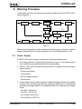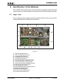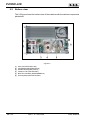
1
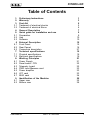
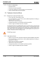
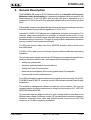
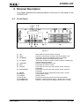
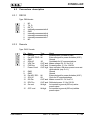
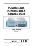
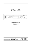
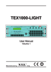
PJ1000C-LCD User Manual Volume 1 Manufactured by Italy File name: PJ1000C-LCD_en.P65 Version: 1.0 Date: 29/10/2003 Revision History 'DWH 9HUVLRQ 5HDVRQ )LUVW9HUVLRQ (GLWRU *'H'RQQR PJ1000C-LCD - User Manual Version 1.0 © Copyright 2003 R.V.R. Elettronica SpA Via del Fonditore 2/2c - 40138 - Bologna (Italia) Telefono: +39 051 6010506 Fax: +39 051 6011104 Email: [email protected] Web: www.rvr.it All rights reserved Printed and bound in Italy. No part of this manual may be reproduced, memorized or transmitted in any form or by any means, electronic or mechanic, including photocopying, recording or by any information storage and retrieval system, without written permission of the copyright owner. Notification of intended purpose and limitations of product use This product is a FM transmitter intended for FM audio broadcasting. It utilises operating frequencies not harmonised in the intended countries of use. The user must obtain a license before using the product in intended country of use. Ensure respective country licensing requirements are complied with. Limitations of use can apply in respect of operating freuency, transmitter power and/or channel spacing. Declaration of Conformity Hereby, R.V.R. Elettronica SpA, declares that this FM transmitter is in compliance with the essential requirements and other relevant provisions of Directive 1999/5/EC. PJ1000C-LCD Table of Contents 1. 2. 3. 3.1 3.2 4. 5. 5.1 5.2 5.3 6 6.1 6.2 6.3 7. 7.1 7.2 8. 8.1 8.2 8.3 8.4 8.5 8.6 8.7 9. 9.1 9.2 Preliminary Instructions Warranty First Aid Treatment of electrical shocks Treatment of electrical Burns General Description Quick guide for installation and use Preparation Use Software External Description Front Panel Rear Pannel Connectors description Technical specifications Physical specifications Electrical specifications Working Principles Power Supply Panel board - CPU Telemetry board PWR Input Measure card Power amplifier LPF card BIAS card Identification of the Modules Upper view Bottom view User Manual Rev. 1.0 - 29/10/03 1 3 5 5 6 7 9 9 10 10 15 15 16 27 19 19 19 21 21 22 22 23 23 23 24 25 25 26 i PJ1000C-LCD This page was intentionally left blank ii Rev. 1.0 - 29/10/03 User Manual PJ1000C-LCD 1. Preliminary Instructions This manual is written as a general guide for those having previous knowledge and experience with this kind of equipment, well conscious of the risks connected with the operation of electrical equipment. It is not intended to contain a complete statement of all safety rules which should be observed by personnel in using this or other electronic equipment. The installation, use and maintenance of this piece of equipment involve risks both for the personnel performing them and for the device itself, that shall be used only by trained personnel. R.V.R. Elettronica SpA doesnt assume responsibility for injury or damage resulting from improper procedures or practices by untrained/unqualified personnel in the handling of this unit. Please observe all local codes and fire protection standards in the operations of this unit. WARNING: always disconnect power before opening covers or removing any part of this unit. Use appropriate grounding procedures to short out capacitors and high voltage points before servicing. WARNING: this device can irradiate radio frequency waves, and if its not installed following the instructions contained in the manual and local regulations it could generate interferences in radio communications. This is a "CLASS A" equipment. In a residential place this equipment can cause hash. In this case can be requested to user to take the necessary measures. R.V.R. Elettronica SpA reserves the right to modify the design and/or the technical specifications of the product and this manual without notice. User Manual Rev. 1.0 - 29/10/03 1 / 26 PJ1000C-LCD This page was intentionally left blank 2 / 26 Rev. 1.0 - 29/10/03 User Manual PJ1000C-LCD 2. Warranty Any product of R.V.R. Elettronica is covered by a 24 (twenty-four) month warranty. For components like tubes for power amplifiers, the original manufacturers warranty applies. R.V.R. Elettronica SpA extends to the original end-user purchaser all manufacturers warranties which are transferrable and all claims are to be made directly to R.V.R. per indicated procedures. Warranty shall not include: 1 Damage while the equipment is being shipped to R.V.R. for repairs; 2 Any unauthorized repair/modification; 3 Incidental/consequential damages as a result of any defect 4 Nominal non-incidental defects 5 Re-shipment costs or insurance of the unit or replacement units/parts Any damage to the goods must be reported to the carrier in writing on the shipment receipt. Any discrepancy or damage discovered subsequent to delivery, shall be reported to R.V.R. Elettronica within 5 (five) days from delivery date. To claim your rights under this warranty, you shold follow this procedure: 1 Contact the dealer or distributor where you purchased the unit. Describe the problem and, so that a possible easy solution can be detected. Dealers and Distributors are supplied with all the information about problems that may occur and usually they can repair the unit quicker than what the manufacturer could do. Very often installing errors are discovered by dealers. 2 If your dealer cannot help you, contact R.V.R. Elettronica and explain the problem. If it is decided to return the unit to the factory, R.V.R. Elettronica will mail you a regular authorization with all the necessary instructions to send back the goods. 3 When you receive the authorization, you can return the unit. Pack it carefully for the shipment, preferably using the original packing and seal the package perfectly. The customer always assumes the risks of loss (i.e., R.V.R. is never responsible for damage or loss), until the package reaches R.V.R. premises. For this reason, we suggest you to insure the goods for the whole value. Shipment must be effected C.I.F. (PREPAID) to the address specified by R.V.R.s service manager on the authorization DO NOT RETURN UNITS WITHOUT OUR AUTHORIZATION AS THEY WILL BE REFUSED User Manual Rev. 1.0 - 29/10/03 3 / 26 PJ1000C-LCD 4 Be sure to enclose a written technical report where mention all the problems found and a copy of your original invoice establishing the starting date of the warranty. Replacement and warranty parts may be ordered from the following address. Be sure to include the equipment model and serial number as well as part description and part number. R.V.R. Elettronica SpA Via del Fonditore, 2/2c 40138 BOLOGNA ITALY Tel. +39 051 6010506 4 / 26 Rev. 1.0 - 29/10/03 User Manual PJ1000C-LCD 3. First Aid The personnel employed in the installation, use and maintenance of the device, shall be familiar with theory and practice of first aid.. 3.1 3.1.1 Treatment of electrical shocks If the victim is not responsive Follow the A-B-C's of basic life support Place victim flat on his backon a hard surface. Open airway: lift up neck, push forehead back (Fig. 3-1). clear out mouth if necessary and observe for breathing if not breathing, begin artificial breathing (Figure 3-2): tilt head, pinch nostrils, make airtight seal, four quick full breaths. Remember mouth to mouth resuscitation must be commenced as soon as possible Figure 3-1 Figure 3-2 Check carotid pulse (Fig 3-3); if pulse is absent, begin artificial circulation (Fig. 3-4) depressing sternum (Fig. 3-5) Figure 3-3 Figure 3-4 Figure 3-5 In case of only one rescuer, 15 compressions alternated to two breaths. If there are two rescuers, the rythm shall be of one brath each 5 compressions. Do not interrupt the rythm of compressions when the second person is giving breath. Call for medical assistance as soon as possible. User Manual Rev. 1.0 - 29/10/03 5 / 26 PJ1000C-LCD 3.1.2 3.2 3.2.1 If victim is responsive Keep them warm Keep them as quiet as possible Loosen their clothing (a reclining position is recommended) Call for medical help as soon as possible Treatment of electrical Burns Extensive burned and broken skin Cover area with clean sheet or cloth Do not break blisters, remove tissue, remove adhered particles of clothing, or apply any salve or ointment. Treat victim for shock as required. Arrange transportation to a hospital as quickly as possible. If arms or legs are affected keep them elevated If medical help will not be available within an hour and the victim is conscious and not vomiting, give him a weak solution of salt and soda: 1 level teaspoonful of salt and 1/2 level teaspoonful of baking soda to each quart of water (neither hot or cold). Allow victim to sip slowly about 4 ounces (half a glass) over a period of 15 minutes. Discontinue fluid if vomiting occurs DO NOT give alcohol 3.2.2 6 / 26 Less severe burns Apply cool (not ice cold) compresses using the cleansed available cloth article. Do not break blisters, remove tissue, remove adhered particles of clothing, or apply salve or ointment. Apply clean dry dressing if necessary. Treat victim for shock as required. Arrange transportation to a hospital as quickly as possible If arms or legs are affected keep them elevated. Rev. 1.0 - 29/10/03 User Manual PJ1000C-LCD 4. General Description The PJ1000C-LCD, made by R.V.R. Elettronica SpA, is an amplifier for Frequency Modulated audio broadcasting in a frequency modulation able to transmit in the band between 87.5 and 108 MHz, with an output RF power adjustable up to a maximum of 1000 W into a 50 Ohm standard load and with a driver power less than 20 W. This amplifier contains a low-pass filter that reduces the harmonic emissions to below the limits allowed by international regulations (CCIR or FCC). Important PJ1000C-LCD features are compactness and great use simplicity. The machine, infact, was designed to be modular: its various functions are run from modules directly connected to each other with male and female connectors or with flat cables ending in connectors. This type of design makes maintenance operations and any required module replacement easier. The RF power section makes use of four MOSFET modules, able to deliver more than 300W each. PJ1000C-LCD is able to work in all range frequency without calibration and setting operations. The microprocessor system includes an LCD display on front panel and push-button panel for interaction with the user, and implements the following functions: Setting the output power Activation and deactivation of power delivery Setting the Power Good threshold Measurement and display of the working parameters of the amplifier Communications with outside devices Four LEDs indicate the machine status and are found on the front panel: ON, LOCK, FOLDBACK and RF MUTE, moreover two red LEDs indicate eventual Power Supply breakdowns. The amplifier's management software is based on a menu system. The user can navigate between the various submenus by using four push buttons: ESC, LEFT/UP, RIGHT/DOWN and ENTER. On rear panel there are Mains connectors, with a voltage selector that allow to use different mains voltage (Full Range version), RF input and output connectors, telemetry connector, protection fuses, input and output interlock connectors and RF Test connector at -60 dB to monitoring modulation. User Manual Rev. 1.0 - 29/10/03 7 / 26 PJ1000C-LCD This page was intentionally left blank 8 / 26 Rev. 1.0 - 29/10/03 User Manual PJ1000C-LCD 5. Quick guide for installation and use This chapter contains the necessary information for installing and using the machine. If any aspects are not completely clear, for example when using the machine for the first time, we recommend you carefully read the entire description contained in this manual. 5.1 Preparation Unpack the amplifier and before doing any other operation, be sure it has not been damaged during transport. In particular check that all the connectors are in perfect condition. Check that the voltage selected coincide with mains voltage. The protection fuses can be accessed from the outside on the rear panel (see figure 6.2). Extract the fuse carrier with a screwdriver to check its integrity or for replacement, if necessary. The fuses to be used are different and depends from the mains voltage selected: Mains Voltage: 115 V Mains Fuse: 25A 10x38 Service Fuse: 2A 5x20 Mains Voltage: 230 V Mains Fuse: 16A 10x38 Service Fuse: 1A 5x20 Connect to the RF Input the RF Output of suitable exciter (for example the RVR Elettronica's PTX30) using a N-connectors terminated cable; the exciter shall be set for minimum power and OFF. Link one of the Alarms/Interlock connectors to the Interlock connector of the exciter, if available (it is in RVR Elettronica's exciters). Connect the RF output to the antenna cable or to a suitable dummy load. ATTENTION: without load, when machine is working, dont touch RF output connector to avoid electrical shocks and burns. Connect the mains cable to the MAINS connector on rear panel (figure 6.2 note [3]). ATTENTION: mains connector is a bare terminals, attention that line is not under voltage when you are connecting it. ATTENTION: It is crucial that the mains system be provided with earthing to ensure both the operators' safety and correct operation of the device. User Manual Rev. 1.0 - 29/10/03 9 / 26 PJ1000C-LCD 5.2 Use Switch ON the amplifier and verify the green "ON" LED is lit. The LCD display will show first screen with the indication of forward and reflected power value. Verify that there is not power limitation: push ENTER button until that it enter in modify mode with the instantaneous power reading and with a series of vertical bars that it indicates power level. Place cursor on series of vertical bars and push RIGHT/DOWN button until bars fill up all the screen. Then, push ENTER button to confirm. Switch ON the exciter (to minimum power level) and wait for it to lock on the working frequency. When the locked condition is reached, progressively increase its output power, while controlling the amplifier's display. Keep increasing the exciter output until the amplifiers output power is over 1000W. Then, come back in modify mode and, through LEFT/UP button, decrease power until its value is 1000 W. Then, push ENTER button to confirm. At this point, you can verify all the amplifiers working parameters using the management software. Normally, the device doesn't require any human supervision for its normal operation. If any alarm conditions happen, these are automatically managed by the embedded protection system, and notified to the user with the LEDs on the panel or through messages on the LCD display. NOTE: When the device leaves the factory, it is delivery with the output power adjustment at maximum and in the OFF position. 5.3 Software The machine is provided with a two-line LCD display where a set of menus is shown. An overall view of the machine's menus is given in figure 5.1. One of the following symbols may be present on the left side of the display, depending on the case: The parameter highlighted by the arrow can be modified The arrow points out the current line, the parameter of which cannot be modified. This symbol is present in the menus made up of more than two lines to help scroll the menu. When turned on, the LCD display shows the predefined screen, with the indication of the forward and reflected power values: 10 / 26 Rev. 1.0 - 29/10/03 User Manual PJ1000C-LCD To change the set power level, select the line relating to the forward power and keep the ENTER push button pressed until it enters the modify mode. The screen that is shown in the modify mode is similar to the following: The upper line gives the instantaneous reading of the power (997 W in this example), whereas the bar indicates the set level. To increase level, press the RIGHT/DOWN push button and to decrease it, press LEFT/UP. As the set level increases or decreases, the bar becomes longer or shorter to display the current setting. When the desired level is reached, press ENTER to confirm and exit the predefined menu. Note that the set value is stored anyway, so if you press ESC or let the timeout go by without pressing a key, the power will remain at the last set level. If you push the ESC button while you are in the predefined menu, it will be shown to user the next selection screen from which you can access all the other menus: To enter one of the submenus, select its name (which will be underlined by a blinking cursor) with the RIGHT or LEFT push buttons and then push the ENTER button. If you instead want to go back to the predefined menu, all you have to do is press the ESC push button again. Figure 5.1 shows the complete set of the machine's menus. User Manual Rev. 1.0 - 29/10/03 11 / 26 PJ1000C-LCD 6ZLWFK RQ (6& (6& 6HOHFWLRQ 0HQX (17(5 2SHUDWLRQ 0HQX)QF (17(5 3RZHU0HQX3ZU (17(5 3RZHU $PS 0HQX3$ (17(5 $ODUP 0HQX$OP (17(5 0LVFHOODQHRXV 0HQX0L[ (17(5 9HUVLRQ 0HQX9UV Figure 5.1 5.4.1 Operation Menu (Fnc) Through this menu the user can activate or deactivate power distribution, set Local or Remote control and set percentage power of Power Good. To modify one of the three functions, select the relative line with UP and DOWN push buttons and then press for a long time the ENTER push button until the command is accepted. So, the Pwr setting will change from On to Off or inverse and the Loc setting will change from "LOCAL" to "REMOTE" or inverse. To change the percentage value of Power Good, after selected PWG voice you must change its value with UP and DOWN push button and then confirm with ENTER. The Power Good function is a distributed power check and alarm function. When output power is under Power Good threshold value, machine changes DB15 Remote connectors pin state on rear panel (see figure 6.2 note [12]). 12 / 26 Rev. 1.0 - 29/10/03 User Manual PJ1000C-LCD Percentage Power Good value is refered to nominal machine power, that is 1000 W, and is not refered to distributed power. So, if you set 80% value, it will correspond to 800 W, indifferently from set up power. 5.4.2 Power Menu (Pwr) This screen shows the user the measures relating to the exciters RF power output: Forward Power (Fwd) Reflected Power (Rfl) Input Power (Inp) The values shown are "readings", and therefore cannot be modified (note the empty triangle). To modify the power setting, use the predefined menu as described above. 5.4.3 Power Amplifier Menu (PA) This screen, consisting by four lines that can be scrolled with UP and DOWN push buttons, shows to user the measures relating to the device's final power amplifier: Voltage (VPA) Current consumption (IPA) Efficiency FWD PWR/(Vpa X Ipa)% (EFF) Temperature (TMP) User Manual Rev. 1.0 - 29/10/03 13 / 26 PJ1000C-LCD 5.4.4 Alarms Menu (Alm) This menu signals the alarm situations that happens during machine working. The screen numbers the alarm situations until 10, they are refered to an excess of forward power, to an excess of reflected power and to an excess of input power. After check the alarm situation, you can reset the numeration placing cursor on Rst voice and pushing for a long time the ENTER button. 5.4.5 Miscellaneous Menu (Mix) This menu allows you to set the machine's address in a o I2C type of serial bus connection: The I2C network address is important when the exciter is connected to an RVR transmission system that envisages use of this protocol. We recommend you do not modify it without a good reason. 5.4.6 Versions Menu(Vrs) This screen shows the version and the release date of the software. 14 / 26 Rev. 1.0 - 29/10/03 User Manual PJ1000C-LCD 6 External Description This chapter describes the elements placed on front and on rear panels of the PJ1000C-LCD. 6.1 Front Panel Figure 6.1 [1] ON [2] LOCK [3] FOLDBACK [4] R.F. MUTE [5] CONTRAST [6] ESC [7] LEFT/UP [8] RIGHT/DOWN [9] [10] [11] [12] [13] [14] User Manual ENTER DISPLAY POWER AIR FLOW ALARMS PS1 ALARMS PS2 Green LED, lit when the exciter is working Red LED, lit when there is an alarm warning (chapter 5.4.4) Yellow LED, lit when the foldback function is operating (automatic reduction of the delivered RF power) Yellow LED, lit when the exciters power output is inhibited by an external interlock command Display contrast adjusting trimmer Push button to exit from a menu Push button to move in the menu system and to modify the parameters Push button to move in the menu system and to modify the parameters Push button to confirm a parameter and to enter in a menu Liquid crystals display ON/OFF switch. Grid for the intake of the air flow of the forced ventilation Red LED, lit when the Power Supply 1 doesnt work correctly Red LED, lit when the Power Supply 2 doesnt work correctly Rev. 1.0 - 29/10/03 15 / 26 PJ1000C-LCD 6.2 Rear Pannel figure 6.2 [1] R.F. TEST [2] [3] [4] [5] [6] [7] [8] [9] [10] [11] [12] [13] [14] [15] 16 / 26 Output at -60 dB refered to output power level, adapted to modulation monitoring. Do not use it for spectral analysis. AIR FLOW Grid for the intake of the air flow ventilation. MAINS Mains supply connectors, 115-230 V 50-60 Hz. FUSE 1 Mains supply fuse. R.F. INPUT RF input connector, N type. R.F. OUT RF output connector, 7/16 type. INTERLOCK IN BNC interlock in connector: the amplifier is forced in stand-by mode when the inner conductor is grounded. FWD EXT. AGC Trimmer for the control of the delivered power in function of the income FWD fold (REMOTE connector). RFL EXT. AGC Trimmer for the control of the delivered power in function of the income RFL fold (REMOTE connector). INTERLOCK OUT BNC interlock out connector: when amplifier is in stand-by mode, the inner conductor, usually floating, become grounded. RS232 DB9 connector for interconnection with other devices and for factory parameters programming. REMOTE DB15 connector for telemetry of the machine. SERVICE VOLTAGE SEL. Mains voltage selector 120-240 V. SERVICE FUSE Service protection fuse. FUSE 2 Mains supply fuse. Rev. 1.0 - 29/10/03 User Manual PJ1000C-LCD 6.3 6.3.1 Connectors description RS232 Type: DB9 female 6.3.2 1 2 3 4 5 6 7 8 9 NC TX_D RX_D Internally connected with 6 GND Internally connected with 4 Internally connected with 8 Internally connected with 7 NC Remote Type: DB15 female User Manual Pin 1 2 3 4 5 6 7 Name Interlock Ext AGC FWD GND SDA IIC VPA Tlm FWD tlm Power Good Type IN IN I/O OUT anal. OUT anal. OUT digit. 8 9 10 11 12 13 14 GND GND Ext AGC RFL SCL IIC IPA Tlm RFL Tlm On cmd IN I/O OUT anal. OUT anal. IN digit. 15 OFF cmd IN digit. Meant Inhibits power if closed to GND External signal for power limitation (AGC) Ground Serial data for IIC communications Mains voltage PA: 5 V for 62 V Forward power: 3 V for 1245 W Open collector, ON when power is over set up threshold (cap. 5.4.1) Ground Ground External signal for power limitation (AGC) Clock for IIC communications Mains current PA: 5 V for 47 A Reflected power: 3 V for 230 W An impulse to ground (500 ms) active power output An impulse to ground (500 ms) inhibits power output Rev. 1.0 - 29/10/03 17 / 26 PJ1000C-LCD This page was intentionally left blank 18 / 26 Rev. 1.0 - 29/10/03 User Manual PJ1000C-LCD 7. Technical specifications 7.1 Physical specifications 7.2 Electrical specifications Panel size Depth Weight Working Temperature Cooling General RF output power Frequency range Spurious and Harmonics suppression Input Drive Power C.A. power supply Power consumption at 1000 W RF Input R.F. Input Connector Input impedance Output R.F. Out Connector Output impedance R.F. Test Connector Remote connections Interlock IN Interlock OUT Serial interface Telemetry card User Manual 483 mm (19) x 132.5 mm (3 HE) 650 mm (26 1/2) 33 Kg -10 °C ÷ 50 °C Forced Ventilation 0 to 1000 W, adjustable with continuity 87.5 MHz ÷ 108 MHz, step 10kHz Respects relevant FCC and CCIR standards (typical -75 dBc) ≅ 20 W ≅ 90 V ÷ 250 V, full-range. Power factor > 0.97 (with PFC) ≅1,7 kVA "N" Type 50 Ω Standard connector 7/16 50 Ω BNC connector, -60 dB wrt. carrier level impedance 50 Ohm BNC female: the amplifier is forced in stand-by mode when the inner conductor is grounded BNC female: when amplifier is in stand-by mode, the inner conductor, usually floating, become grounded DB9 female RS232 DB15 female, give indications on the state of the device Rev. 1.0 - 29/10/03 19 / 26 PJ1000C-LCD This page was intentionally left blank 20 / 26 Rev. 1.0 - 29/10/03 User Manual PJ1000C-LCD 8. Working Principles A schematic view of the modules and connections making up the PJ1000C-LCD is shown in figure 8.1. R.F. INPUT PWR INPUT MEASURE R.F. 4 X R.F. SPLITTER 4 X R.F. RF MODULES R.F. COMBINER LPF + DIRECT. COUPL. R.F. OUTPUT BIAS 4 X VPA (50VDC) FUSE BOARD FWD PWR RFL PWR 4 X VPA (50VDC) BIAS VOLTAGE REG. MAINS INTERFACE 4 X 50VDC PANEL PS ALARM DC SURGE PROT. PFC (RECTIFIER) ALIM 50V 25A LED CARD TELEMETRY Figure 8.1 Below a brief description of each module's functions is given, while the complete diagrams and layouts of the cards are given in the Technical appendix in vol.2. 8.1 Power Supply PJ1000C-LCD power supply is composed by three important sections: 1. Over range protection. Surge Protection board (see cap. 8.1.1) protects machine from eventual unexpected variations of the mains voltage . 2. Service. This section contains elements that do not regard directly the power supply, they are: - Service transformer - Power switch - Service voltage selector - Service fuse 3. Power Supply. Various units supplies an adapted supply to RF power amplifier modules. The units that compose power supply are rectifiers (PFC or traditionals) and switching supply. Machine is available in different configuration for voltage rectify: - One PFC (only 230 V) - Two PFC (115-230 V) - One rectifier (only 230 V) - Two rectifiers (115-230 V) User Manual Rev. 1.0 - 29/10/03 21 / 26 PJ1000C-LCD 8.1.1 Surge Protection This card contains two mains fuse accessible from outside (figure 6.2 note [4] and [15]) and it contains a MOV battery to protect main supply and machine from over range mains voltage. Then the mains voltage reaches the main Power switch placed on front panel and, if it is on ON state, mains voltage arrives to TR1 service transformer. One of its secondary output generates (through interface card) 24V voltage that excites power relè placed on Surge card, so PFC or rectifier units, connect to it, will be on voltage. 8.1.2 PFC board (rectifiers) PFC units are rectifiers that modulates absorbed current so that the wave shape is sinusoide, having so 99% power factor. PFC can work with input mains voltage from 90 V to 250 V. When you use it with mains voltage of 110 V, is necessary to install two PFC units because there is a lot of absorbed current. In PFC output there are 350 V of rectified voltage. You can replace PFC units with one or two traditional rectifying units (but without power factor protection). 8.1.3 Power supply There are two power supply switching mode of 50 V 25 A, that have an input voltage check. Output voltage is set from microprocessor in function of RF power required. Two power supply units works in parallel mode and they have a balance current circuit so that the distributed current from every module is approximately the same one. 8.2 Panel board - CPU The panel card contains the microcontroller (PIC16F877) that implements the machine's control software, the display and the other components needed to interface the user. The card interfaces with the other machine modules, both for power supply distribution and for the control and measures. 8.3 Telemetry board This card is the input/output CPU interface with external world. All the available input and output signals are replied on the DB15 REMOTE connector (see cap. 6.3.2). On the same board there is also the BNC connector of interlock to disable device. Closing the central pin to ground, the output power is reduced to zero until connection doesnt removed. 22 / 26 Rev. 1.0 - 29/10/03 User Manual PJ1000C-LCD When it is used with a R.V.R. exciter, this connector is connected, through a BNC-BNC connector, to REMOTE or to INTERLOCK of the exciter. In case of breakdowns of the exciter, the central conductor is place to ground forcing the device to enter in stand-by mode. 8.4 PWR Input Measure card This card makes two check and measure functions: 8.5 - Input power measure, measure sended to interface card that supplies to send machine in protection mode in case of input power excess - Temperature measure Power amplifier RF power amplifier section is made with four power amplifier modules combined through a Wilkinson splitter and a Wilkinson combiner in strip-line technology. The splitter is used to divide input power from PWR Input Measure card and to supply a quarter of it to every RF module. The combiner is used to combine output power from every RF module so as to have total power amplifier. Splitter, amplifier and combiner are plans so that powers generated from the amplifiers add its in phase, diminishing the loss of balance and therefore the dissipation of useful power. All RF section is placed on a fin that supplies to the cooling through forced ventilation. Every RF module supplies 300 W and is supplied from a switching supply. The active device used in amplifier module is a Mosfet (BLF278). 8.6 LPF card This card is a low-pass filter and its function is to suppress the harmonic components generated by the amplifier below the levels required by regulations. Moreover, in the end of filter, there is a directional coupler, its function is the measurement of the forward and reflected output power. On this card there is an RF sample at -60 dB compared with the output and it is available on a BNC connector. This sample is useful for checking the characteristics of the carrier, but not of the higher order harmonics. User Manual Rev. 1.0 - 29/10/03 23 / 26 PJ1000C-LCD 8.7 BIAS card Main function, of this card, is to check and to correct the polarization voltage (BIAS) of Mosfet in RF amplifier section. Moreover it supplies the measure of the absorbed current as sum of the absorbed currents from every module and it contains a circuit for the signalling of the breakdowns in the Power Supply. Without alarm condition, Bias voltage is regulated only in function of output power set up, with a feedback mechanism based on the reading of the effectively distributed power (AGC). Bias voltage is also influenced from other factors like: - Excess of reflected voltage - External AGC signals (Ext. AGC FWD, Ext. AGC RFL,...) - Excess of temperature - Excess of absorbed current from a RF module. 24 / 26 Rev. 1.0 - 29/10/03 User Manual PJ1000C-LCD 9. Identification of the Modules The PJ1000C-LCD is made up of various modules connected to each other with connectors so as to make maintenance and any required module replacement easy. 9.1 Upper view The 9.1 figure shows the upper view of the machine (230 V version, only one PFC module) with the various components pointed out. Figure 9.1 [1] [2] [3] [4] [5] [6] [7] [8] [9] [10] [11] [12] [13] [14] [15] [16] User Manual Bias Board (SLBIAS1K3U-2) Pass Thru Board (SLFILPJ1KM) LPF Board (SLLPFTEX1KL) Panel Board (SLPANTXLC004) Impeller FAN1 (VTL4184) Alim 50V 25A Module 1 (PSL1000_PJ1K) Alim 50V 25A Module 2 (PSL1000_PJ1K) Power Factor Module 1 (PFCPSL1000) Surge Protection Board (SLSRGPRPJ1KM) Telemetry Board (SLTLMTXLCD02) Turbine FAN2 (VTLG1E120) PWR Input Measure Board (SLDRVTEX500L) Splitter Card (SLSPLPJ1KC1) RF Board (SLRFPJKMU44) Combiner Card (SLCMBPJ1KC1) Fuse Board (SLFUSRFPJ1KC) Rev. 1.0 - 29/10/03 25 / 26 PJ1000C-LCD 9.2 Bottom view The 9.2 figure shows the bottom view of the machine with the various components pointed out. Figura 9.2 [1] [2] [3] [4] [5] [6] 26 / 26 Filter Card (SLFILPSPJ1KC) LED PS Board(SLLEDPSTEX1K) Interface Board (SLINTTX500-2) Trasformer TR1 (TRFTEX1000T) Bare Terminals MO1 (MORSWDMK3/12) Telemetry Board (SLTLMTXLCD02) Rev. 1.0 - 29/10/03 User Manual