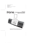
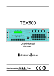
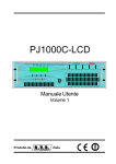
1
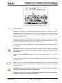
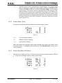
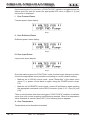
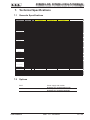
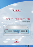
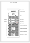
PJ500C-LCD, PJ700C-LCD & PJ1000-LIGHT User Manual Volume 1 Manufactured by Italy File Name: 03_PJ500C-LCD_PJ700C-LCD&PJ1000light_ING_1.0.indd Version: 1.0 Date: 24/06/2008 Document History Date Version 24/06/08 1.0 Reason First Edition Editor J.H. Berti PJ500C-LCD, PJ700C-LCD & PJ1000-LIGHT - User Manual Version 1.0 © Copyright 2008 R.V.R. Elettronica SpA Via del Fonditore 2/2c - 40138 - Bologna (Italia) Telephone: +39 051 6010506 Fax: +39 051 6011104 Email: [email protected] Web: www.rvr.it All rights reserved Printed and bound in Italy. No part of this manual may be reproduced, memorized or transmitted in any form or by any means, electronic or mechanic, including photocopying, recording or by any information storage and retrieval system, without written permission of the copyright owner. PJ500C-LCD, PJ700C-LCD & PJ1000light Table of Contents 1. 2. 3. 3.1 3.2 4. 4.1 5. 5.1 5.2 5.3 5.4 6. 6.1 6.2 6.3 7. 7.1 7.2 8. 8.1 8.2 8.3 8.4 8.5 8.6 8.7 8.8 9. 9.1 9.2 9.3 9.4 Preliminary Instructions Warranty First Aid Treatment of electrical shocks Treatment of electrical Burns Unpacking General Description Quick guide for installation and use Preparation First power-on and setup Operation Management Firmware Front and Rear Panel Description Front Panel Rear Panel Connectors description Technical Specifications Generals Specifications Options Operating principles Power supply Interface board (SL010IN5001) Panel board - CPU (SL007PC2003) PWR Input Measure Board (SLMPIPPJ1KC) Power amplifier LPF Board (SLLPFTEX1KL) BIAS board (SLBIAS1K3U-2) External Telemetry Interface Board (SLTLMTXLCD03) Identification and Access to the Modules Top View (PJ500C-LCD) Bottom View (PJ500C-LCD) Top View (PJ500C-LCD) Bottom View (PJ500C-LCD) User Manual Rev. 1.0 - 20/06/08 1 1 1 1 2 3 3 5 5 8 11 13 20 20 21 22 23 24 26 24 24 26 26 27 27 27 28 28 29 29 30 31 32 PJ500C-LCD, PJ700C-LCD & PJ1000light This page was intentionally left blank ii Rev. 1.0 - 20/06/08 User Manual PJ500C-LCD, PJ700C-LCD & PJ1000light To claim your rights under this warranty, you shold follow this procedure: 1. Preliminary Instructions 1 This manual is written as a general guide for those having previous knowledge and experience with this kind of equipment, well conscious of the risks connected with the operation of electrical equipment. It is not intended to contain a complete statement of all safety rules which should be observed by personnel in using this or other electronic equipment. Dealers and Distributors are supplied with all the information about problems that may occur and usually they can repair the unit quicker than what the manufacturer could do. Very often installing errors are discovered by dealers. The installation, use and maintenance of this piece of equipment involve risks both for the personnel performing them and for the device itself, that shall be used only by trained personnel. R.V.R. Elettronica SpA doesn’t assume responsibility for injury or damage resulting from improper procedures or practices by untrained/unqualified personnel in the handling of this unit. 2 If your dealer cannot help you, contact R.V.R. Elettronica and explain the problem. If it is decided to return the unit to the factory, R.V.R. Elettronica will mail you a regular authorization with all the necessary instructions to send back the goods; 3 When you receive the authorization, you can return the unit. Pack it carefully for the shipment, preferably using the original packing and seal the package perfectly. The customer always assumes the risks of loss (i.e., R.V.R. is never responsible for damage or loss), until the package reaches R.V.R. premises. For this reason, we suggest you to insure the goods for the whole value. Shipment must be effected C.I.F. (PREPAID) to the address specified by R.V.R.’s service manager on the authorization Please observe all local codes and fire protection standards in the operations of this unit. WARNING: always disconnect power before opening covers or removing any part of this unit. Please observe all local codes and fire protection standards in the operations of this unit. WARNING: this device can irradiate radio frequency waves, and if it’s not installed following the instructions contained in the manual and local regulations it could generate interferences in radio communications. R.V.R. Elettronica SpA Via del Fonditore, 2/2c 40138 BOLOGNA ITALY Tel. +39 051 6010506 Any product of R.V.R. Elettronica is covered by a 24 (twenty-four) month warranty. For components like tubes for power amplifiers, the original manufacturer’s warranty applies. R.V.R. Elettronica SpA extends to the original enduser purchaser all manufacturers warranties which are transferrable and all claims are to be made directly to R.V.R. per indicated procedures. Warranty shall not include: Be sure to enclose a written technical report where mention all the problems found and a copy of your original invoice establishing the starting date of the warranty. Replacement and warranty parts may be ordered from the following address. Be sure to include the equipment model and serial number as well as part description and part number. R.V.R. Elettronica SpA reserves the right to modify the design and/or the technical specifications of the product and this manual without notice. 2. Warranty DO NOT RETURN UNITS WITHOUT OUR AUTHORIZATION AS THEY WILL BE REFUSED 4 This is a “CLASS A” equipment. In a residential place this equipment can cause hash. In this case can be requested to user to take the necessary measures. Contact the dealer or distributor where you purchased the unit. Describe the problem and, so that a possible easy solution can be detected. 3. First Aid The personnel employed in the installation, use and maintenance of the device, shall be familiar with theory and practice of first aid. 3.1 3.1.1 Treatment of electrical shocks If the victim is not responsive 1 Re-shipment of the unit to R.V.R. for repair purposes; 2 Any unauthorized repair/modification; • Place victim flat on his backon a hard surface. 3 Incidental/consequential damages as a result of any defect; • Open airway: lift up neck, push forehead back 4 Nominal non-incidental defects; 5 Re-shipment costs or insurance of the unit or replacement units/parts. Follow the A-B-C’s of basic life support. (Figure 1). Any damage to the goods must be reported to the carrier in writing on the shipment receipt. Any discrepancy or damage discovered subsequent to delivery, shall be reported to R.V.R. Elettronica within 5 (five) days from delivery date. Figure 1 User Manual Rev. 1.0 - 20/06/08 / 32 PJ500C-LCD, PJ700C-LCD & PJ1000light • clear out mouth if necessary and observe for breathing • if not breathing, begin artificial breathing (Figure 2): tilt head, pinch nostrils, make airtight seal, four quick full breaths. Remember mouth to mouth resuscitation must be commenced as soon as possible. • Treat victim for shock as required. • Arrange transportation to a hospital as quickly as possible. • If arms or legs are affected keep them elevated. If medical help will not be available within an hour and the victim is conscious and not vomiting, give him a weak solution of salt and soda: 1 level teaspoonful of salt and 1/2 level teaspoonful of baking soda to each quart of water (neither hot or cold). Allow victim to sip slowly about 4 ounces (half a glass) over a period of 15 minutes. Discontinue fluid if vomiting occurs. Figure 2 • Check carotid pulse (Figure 3); if pulse is absent, begin artificial circulation (Figure 4) depressing sternum (Figure 5). Figure 3 DO NOT give alcohol. 3.2.2 Less severe burns Figure 4 • Apply cool (not ice cold) compresses using the cleansed available cloth article. • Do not break blisters, remove tissue, remove adhered particles of clothing, or apply salve or ointment. • Apply clean dry dressing if necessary. • Treat victim for shock as required. • Arrange transportation to a hospital as quickly as possible. • If arms or legs are affected keep them elevated. Figure 5 3.1.2 3.2 3.2.1 / 32 • In case of only one rescuer, 15 compressions alternated to two breaths. • If there are two rescuers, the rythm shall be of one brath each 5 compressions. • Do not interrupt the rythm of compressions when the second person is giving breath. • Call for medical assistance as soon as possible. If victim is responsive • Keep them warm. • Keep them as quiet as possible. • Loosen their clothing (a reclining position is recommended). • Call for medical help as soon as possible. Treatment of electrical Burns Extensive burned and broken skin • Cover area with clean sheet or cloth. • Do not break blisters, remove tissue, remove adhered particles of clothing, or apply any salve or ointment. Rev. 1.0 - 20/06/08 User Manual PJ500C-LCD, PJ700C-LCD & PJ1000light 4. Unpacking The package contains: 1 PJ500C-LCD, PJ700C-LCD & PJ1000-LIGHT 1 User Manual 1 Mains power cable The following accessories are also available from Your R.V.R. Dealer: • Accessories, spare parts and cables 4.1 General Description PJ500C-LCD, PJ700C-LCD e PJ1000light are compact radio broadcasting amplifier manufactured by R.V.R. Elettronica SpA featuring adjustable RF power output up to 500, 700 and 1000 W, respectively, under 50 Ohm standard load and less than 20W drive power requirement. PJ500C-LCD, PJ700C-LCD and PJ1000light have been designed for installation in a 19”x3HE box for rack. These amplifiers incorporates a low-pass filter to keep harmonics below the limits provided for by international standards (CCIR, FCC or ETSI). Two major features of PJ500C-LCD, PJ700C-LCD and PJ1000light are compact design and user-friendliness. Another key feature is its modular-concept design: the different functions are performed by modules with most connections achieved through male and female connectors or through flat cables terminated by connectors. This design facilitates maintenance and module replacement. The RF power section of PJ500C-LCD uses two MOSFET modules delivering up to 300W output power each, PJ700C-LCD uses two MOSFET modules delivering up to 350W output power each, whereas PJ1000light features three MOSFET modules with up to 350 W output power each. An LCD on the front panel and a push-button panel provide for user interfacing with the microprocessor control system, which implements the following features: • Output power setup • Power output enable/disable • User-selectable threshold settings for output power alarm (Power Good feature) • Measurement and display of amplifier operating parameters • Communication with external devices, as programming systems or telemetry systems through RS232 or I2C serial interface User Manual Rev. 1.0 - 20/06/08 / 32 PJ500C-LCD, PJ700C-LCD & PJ1000light Four LEDs on the front panel provide for machine status indication (ON, FAULT/ LOCK, FOLDBACK, RF MUTE) and two yellow LEDs provide Power Supply fault indication. The amplifier management software is based on a menu system. User has four navigation buttons available to browse submenus: ESC, , , and ENTER. The rear panel features the mains input connectors with a mains voltage switch (chap. 6.2) to select the appropriate mains input voltage, RF input and output connectors, telemetry connector, protection fuses, interlock input and output connectors and a BNC connector that provides an RF test point with level being -60 dB lower than power ouput. / 32 Rev. 1.0 - 20/06/08 User Manual PJ500C-LCD, PJ700C-LCD & PJ1000light 5. Quick guide for installation and use This section provides a step-by-step description of the machine installation and configuration procedure. Follow these procedures closely upon first power-on and each time any change is made to general configuration, such as when a new transmission station is added or the exciter is replaced. Once the desired configuration has been set up, no more settings are required for normal operation; at each power-up (even after an accidental shutdown), the amplifier defaults to the parameters set during the initial configuration procedure. The topics covered in this section are discussed at greater length in the next sections, with detailed descriptions of all hardware and firmware features and capabilities. Please see the relevant sections for additional details. IMPORTANT: When configuring and testing the transmitter in which the amplifier is integrated, be sure to have the Final Test Table supplied with the machine ready at hand throughout the whole procedure; the Final Test Table lists all operating parameters as set and tested at the factory. 5.1 Preparation 5.1.1 Preliminary checks Unpack the amplifier and immediately inspect it for transport damage. Ensure that all connectors are in perfect condition. Provide for the following (applicable to operating tests and putting into service): √ Single-phase 230 VAC or 115 VAC (-15% / +10%) mains power supply with adequate ground connection √ FM exciter with adjustable output power up to 20W (as a minimum), like RVR Elettronica PTX30-LCD √ For operating tests only: dummy load with 50 Ohm impedance and adequate capacity (500w for PJ500C-LCD, 700w for PJ700C-LCD or 1000 W for PJ1000light as a minimum) √ Connection cable kit including: • Mains power cable User Manual Rev. 1.0 - 20/06/08 / 32 PJ500C-LCD, PJ700C-LCD & PJ1000light 5.1.2 Mains power supply WARNING: Disconnect mains power supply before beginning these procedures. Both power supply units (please see chapter 8.1 for a detailed description) are equipped with fuses and voltage selection blocks: check all fuses and voltage selection blocks to ensure they are properly rated for the power mains and change them as required to match mains voltage. All mains power supply protection fuses are conveniently located on the rear panel and are easily accessed (see figure 6.2): to check or replace a fuse, disconnect machine from power mains, unscrew fuse cover and pull fuse out of socket. The following fuses are used: Main Power Supply (fig. 6.2 – item [7] e [20]) Service power supply ( fig. 6.2 – item [19]) PJ500C-LCD / PJ700C-LCD @ 230 Vac/115 Vac PJ1000light @ 230 Vac/115 Vac (2x) 25A type 10x38 (2x) 25A type 10x38 (1x) 1A type 5x20 (1x) 2A type 5x20 Table 5.1: Fuses Ensure that machine is appropriately set for available mains voltage (supply voltage rating is reported in the Final Test Table) as follows: disconnect machine from mains and ensure that the voltage selection block of the power supply located on the rear panel (see fig. 6.2) is set to the appropriate voltage; change setting as required. The main power supply unit is the full-range type and requires no voltage setup. When supply voltage is other than 230 Vac and might cause erratic operation (say, less than 200 Vac), it may help to move jumper JP3 on the PFC controller board from position 2-3 to 1-2 (see PFCPSL1000 diagram, in figure 9.1 and detail in figure 5.1 below). / 32 Rev. 1.0 - 20/06/08 User Manual PJ500C-LCD, PJ700C-LCD & PJ1000light Figure 5.1: Voltage selection jumper on PFC 5.1.3 Connections Connect the output of a suitable FM exciter (for instance, PTX30-LCD exciter available from R.V.R. Elettronica) to the RF input (see figure 6.2) using a 50-Ohm coaxial cable with suitable connectors. To begin with, set exciter to minimum output power and switch if off. Connect the amplifier INTERLOCK OUT output (figure 6.2) to the matching INTERLOCK IN input fitted on all R.V.R. Elettronica exciters as standard; if your exciter is a different brand, identify an equivalent input. Connect the RF output (see figure 6.2) to an adequately rated dummy load or to the antenna. WARNING: Electric shock hazard. Never handle the RF output connector when the machine is powered on and no load is connected. Injury or death may result. Ensure that the POWER switch on the front panel (see figure 6.1) is set to “OFF”. Connect the mains power cable to the MAINS terminal board on the rear panel (see figure 6.2). Note : The mains must be equipped with adequate ground connection properly connected to the machine. This is a pre-requisite for ensuring operator safety and correct operation. WARNING: The power supply connector is a terminal board. Ensure the wire is not live before performing the connection. Please see figure 5.2 for a hook-up diagram showing RF connection between amplifier and exciter and load connection. User Manual Rev. 1.0 - 20/06/08 / 32 PJ500C-LCD, PJ700C-LCD & PJ1000light Figure 5.2: Connection to exciter 5.2 First power-on and setup Follow this procedure upon first power-on and after making changes to the configuration of the transmitter in which the amplifier is integrated. Note : Standard factory settings are RF power output Off (Pwr OFF) and output power set to upper limit (unless otherwise specified by customer). 5.1.2 Pilot exciter setup Set up the pilot exciter so that the output power it delivers to a matched load equals the maximum input power indicated in the amplifier final test table, switch off the exciter and connect it to the amplifier. 5.2.2 Power-on When you have performed all of the connections described in the previous paragraph, power on the amplifier using the suitable power switch on the front panel (figure 6.1). Power on the pilot exciter. / 32 Rev. 1.0 - 20/06/08 User Manual PJ500C-LCD, PJ700C-LCD & PJ1000light 5.2.3 Power check Ensure that the ON light turns on (see figure 6.1). Machine name should appear briefly on the display, quickly followed by forward and reflected power readings (figure 5.2 - menu 1). If RF output is disabled, these readings will be zero. 5.2.4 How to enable Local mode and RF output Check current mode setting and enable Local mode (if not already enabled) following menu path Fnc ⇒ Loc ⇒ Local (figure 5.2 - menu 4): if left disabled, the machine will not accept the next commands. Check current RF output setting and enable output (if not already enabled) following menu path Fnc ⇒ Pwr ⇒ ON (figure 5.2 - menu 4) Check output power level and set to maximum level (if not already set to maximum) from the Power Setup Menu, which you can call up by pressing these keys in the order: ESC (opens Default Menu) ⇒ ENTER (hold down for 2 seconds) ⇒ SET ⇒ use key to set bar to maximum limit (figure 5.2 - menu 2). 5.2.5 Input power check and setup Go to Pwr menu (figure 5.2 - menu 5) and look up forward output power Fwd, reflected power Rfl and input power Inp readings. With drive power set as specified in the Final Test Table, amplifier output power should be 500W (for model PJ500C-LCD), 700W (for model PJ700C-LCD) or 1000W (for model PJ1000-light) or higher: if needed, fine tune drive power until achieving rated output power. Never exceed 550W (for model PJ500C-LCD), 770W (for model PJ700C-LCD) or 1100W (for model PJ1000-light) output power. Note : Normally, drive power should not exceed 20W (typically 18W): higher drive power requirements are a symptom of abnormal operation. WARNING: Drive power levels above 20W (typically 25W), result in exceeding input power, which causes a temporary amplifier lock-out (see section 5.3.4.1 - Alarms and Faults for more details). 5.2.6 RF output power level control IMPORTANT: The amplifier incorporates Automatic Gain Control and output power is modulated based on the power level set by the user and actual operating conditions, such as temperature, reflected power and other parameters. Drive power must be kept steady at maximum output power capacity. Please read section 5.3 for more details of RF power modulation. User Manual Rev. 1.0 - 20/06/08 / 32 PJ500C-LCD, PJ700C-LCD & PJ1000light Open the Power setup menu (figure 5.2 - menu 2) pressing the following keys in the order: ESC (opens Default Menu) ⇒ ENTER (hold down for 2 seconds) Use SET menu and keys to set the desired amplifier output power; the SET bar at the side provides a graphic display of set power, whereas the forward power value shown on the display (Fwd: xxxx W) gives actual output power reading, and may be lower than set power if an Automatic Gain Control is in limitedpower mode (please read section 5.3 concerning RF power modulation for more details”. Note : Output power can also be set in a Pwr OFF condition; in this condition, (Fwd) output power reading on the display will be 0 (zero), whereas the SET bar, which you can control using the keys, provides a graphic display of the amount of power that will be delivered the moment you switch back to Pwr ON state. 5.2.7 Changing the Power Good alarm threshold Change Forward Power Good alarm setting PgD from the Fnc menu as required (factory setting is 50%). Please read section 5.3.1 for more details. 5.2.8 Changing machine I2C address Change the IIC address in the Mix menu as required (factory setting is 01). Please read section 5.3.5 for more details. 5.2.9 How to enable Remote mode If you wish to use the telemetry control feature, enable Remote control in the Fnc menu (see section 5.3.1 for details). Note : In the Remote mode, all local push-button controls except Remote/Local (for switching back to Local mode) are disabled . Operating parameter readings are available. 10 / 32 Rev. 1.0 - 20/06/08 User Manual PJ500C-LCD, PJ700C-LCD & PJ1000light 5.3 Operation NOTE: For better clarity, only the typical screens of PJ1000light are reported below. PJ500C-LCD and PJ700C-LCD screens look the same except that full scale values are different. 1) Power on the amplifier (chap. 6.1) and ensure that the ON light turns on (chap. 6.1). Machine name should appear briefly on the display, quickly followed by forward and reflected power readings (Menu 1), provided that the amplifier is delivering output power. Menu 1 1b) To modify power level setting, hold down the ENTER button until opening the power setup menu. The edit screen will look like this: Menu 2 Next to SET indication, a bar provides a graphic display of preset output power. The filled portion of the bar is proportional to set power level. Example 100% output power 50% output power 25% output power User Manual Full bar Half bar 1/4 bar Rev. 1.0 - 20/06/08 ≅ 1000W in output (mod.PJ1000light) ≅ 700W output (mod.PJ700C-LCD) ≅ 500W output (mod.PJ500C-LCD) ≅ 500W in output (mod.PJ1000light) ≅ 350W output (mod.PJ700C-LCD) ≅ 250W output (mod.PJ500C-LCD) ≅ 250W in output (mod.PJ1000light) ≅ 175W output (mod.PJ700C-LCD) ≅ 125W output (mod.PJ500C-LCD) 11 / 32 PJ500C-LCD, PJ700C-LCD & PJ1000light The bottom line provides instantaneous power reading (997W in this instance); press button to increase level, press to decrease it. When you have achieved the desired level, press ENTER to confirm and exit the default menu. Please note that the setting is stored automatically; in other words, if you press ESC or do not press any keys before the preset time times out, the latest power level set will be retained. NOTE: This feature prevents the machine from delivering maximum power as soon as output is enabled from menu 4, or in the event the machine is already set to ON and energised. 2) Ensure that machine is not in a locked-out state. Press the ESC key (chap. 6.1) to call up the selection screen (Menu 3). Highlight Fnc and press ENTER to confirm (chap. 6.1) and access the appropriate menu (menu 4). If LOC is set to REMOTE (machine remote control), move cursor to LOC and press ENTER (chap. 6.1); label will change to LOCAL, i.e. local control operation mode. In the same menu, ensure that power limiting is disabled: if PWR is set to OFF, i.e. power output is disabled, move cursor to PWR. Press ENTER (chap. 6.1) and label will switch to ON, i.e. power output enabled. Press ESC (chap. 6.1) twice to go back to the default menu (menu 1). 3) Fine tune power setting from menu 2 (see description of item 1b) until achieving the desired value. WARNING:Equipment is capable of delivering more than rated output power (500W for PJ500C-LCD, 700W for PJ700C-LCD or 1000 W for PJ1000-LIGHT); however, never exceed the specified power rating. NOTE: Exciter drive power setting should never exceed 20W, or it will trigger an Overdrive Alarm. NOTE: If power is set to 0 W in the edit mode, the INTERLOCK OUT contact (chap. 6.2) trips and external exciter power is immediately inhibited. Next, you can review all operating parameters of the machine through the management firmware. Normally, the machine can run unattended. Any alarm condition is handled automatically by the safety system or is signalled by the LED indicators on the panel or by display messages. 12 / 32 NOTE: Standard factory settings are: output power set to upper limit (unless otherwise specified by customer) and OFF. Rev. 1.0 - 20/06/08 User Manual PJ500C-LCD, PJ700C-LCD & PJ1000light 5.4 Management Firmware The machine features an LCD with two lines by 16 characters that displays a set of menus. Figure 5.2 below provides an overview of machine menus. The symbols listed below appear in the left portion of the display as appropriate: (Cursor) - Highlights selected (i.e. accessible) menu. (Filled arrow) - Editable parameter marker. This symbol appears in menus that take up more than two lines to aid browsing. (Three empty arrows) - Parameter is being edited. (Empty arrow) - Current line marker; the parameter in this line cannot be edited. This symbol appears in menus that take up more than two lines to aid browsing. Menu Menu 22 Menu Menu 11 Default Menu Power Setup Menu Menu Menu 33 Selection Screen Menu Menu 44 Operation Menu Menu Menu 55 Power Menu Menu Menu 66 P.A. Menu Menu Menu 77 Alarm Menu Menu Menu 88 Miscellaneous menu Menu Menu 99 Version Menu Figure 5.2 User Manual Rev. 1.0 - 20/06/08 13 / 32 PJ500C-LCD, PJ700C-LCD & PJ1000light When the display is off, touching any key will turn on backlighting. When the display is on, pressing the ESC button (chap. 6.1) from the default menu (menu 1) calls up the selection screen (menu 3), which gives access to all other menus: Menu 3 To gain access to a submenu, select menu name (name is highlighted by cursor) using button or and press the ENTER button (chap. 6.1). Press ESC again (chap. 6.1) to return to the default menu (menu 1). 5.4.1 Operation Menu (Fnc) In this menu, you can set power output On/Off, toggle between “Local” or “Remote” control mode and set the Forward Power Good (PgD) threshold rate. To edit an item, highlight the appropriate line using the UP and DOWN buttons and then press and hold the ENTER button (chap. 6.1) until the command is accepted. This way, Pwr setting is toggled between On and Off and Mod setting is toggled between “x1” and “x10”. To edit the Power Good rate, simply select item “PgD” and edit its value using buttons and ; finally, press ENTER to confirm (chap. 6.1). Menu 4 Pwr Loc 14 / 32 Enables (ON) or disables (OFF) amplifier power output. Modifies machine operation. In the LOCAL mode, the machine can read and modify its operating parameters through the navigation keys and the management firmware, whereas all other sources are locked out. In the REMOTE mode, the machine can only read its operating parameters; parameters are modified based on the commands received from other connected telemetry systems. Rev. 1.0 - 20/06/08 User Manual PJ500C-LCD, PJ700C-LCD & PJ1000light PgD Modifies Power Good threshold for forward power. The Power Good rate is a percent of equipment rated power (500W for PJ500C-LCD, 700W for PJ700C-LCD and 1000 W for PJ1000-LIGHT), not of forward output power. This means that this threshold set at 50% will give 250, 350 and 500 W, respectively, regardless of set power level. The Power Good feature enables output power control and reporting. When output power drops below set Power Good threshold, the equipment changes the state of pin [7] of the DB15 “Remote” connector located on the rear panel (figure 6.2). 5.4.2 Power Menu (Pwr) This screen holds all readings related to machine output power: Menu 5 Fwd Rfl Inp Forward power reading. Reflected power reading. Input power reading. Note that these are readings, rather than settings, and cannot be edited (note the empty arrow). To change power setting, go to the default menu (menu 1) as outlined earlier. 5.4.3 Power Amplifier (P.A) Menu This screen is made up of four lines that can be scrolled using the buttons , shows the readings relating to final power stage: and Menu 6 User Manual Rev. 1.0 - 20/06/08 15 / 32 PJ500C-LCD, PJ700C-LCD & PJ1000light Note that these are readings, rather than settings, and cannot be edited (note the empty arrow). VPA IPA Voltage supplied to amplifier module. Current absorbed to amplifier module. Eff Efficiency based on ratio of forward power to amplifier module power in percent ( FWD PWR/(Vpa x Ipa) % ). Tmp Machine internal temperature. 5.4.4 Alarm Menu (Alm) This menu shows any alarm conditions occurring during machine operation. Alarm thresholds are preset at the factory. Menu 7 FWD RFL INP Counter of alarm conditions triggered by forward power. Counter of alarm conditions triggered by reflected power. Counter of alarm conditions triggered by input power. Reset Alm Alarm counter reset. Alarm conditions are numbered from 1 to 10 and reflect the following situations: forward output power too high, reflected output power too high and input power too high. Alarm monitoring cycle is as follows: when an alarm condition is detected, alarm counter increases by 1 unit, machine goes into lock-out state and the display shows the cause for the stop (chap. 5.3.4.1). After 15 seconds, the machine attempts to re-start; if a new alarm condition is detected, cycle is repeated over and over again up to 10 times maximum. If machine re-starts successfully, all alarm counters are reset after 30 minutes’ regular operation. After 10 alarm conditions triggered by the same cause, the machine goes into fault lock-out mode, a lock-out mode warning appears on the display and the “FAULT/LOCK” LED turns on (chap. 6.1). 16 / 32 Rev. 1.0 - 20/06/08 User Manual PJ500C-LCD, PJ700C-LCD & PJ1000light After the alarm condition has been rectified, the counter can be reset by highlighting “Reset Alm” and holding down the ENTER key for some time (chap. 6.1). 5.4.4.1 Alarms and Faults There are three types of alarms that can cause a machine lock-out and trigger a “FAULT/LOCK” indication. When any one of the three alarm thresholds is exceeded, the system will automatically switch to the warning screen (even though the user is browsing system menus) and the following messages are displayed: 1. Over Forward Power Forward power threshold exceeded. Alarm 1 2. Over Reflected Power Reflected power threshold exceeded. Alarm 2 3. Over Input Power Input power threshold exceeded. Alarm 3 Monitoring cycle is as follows: • An alarm condition occurs; • Alarm is displayed and device is locked out for 15 sec.; • Operating conditions are restored; • Verification. User Manual Rev. 1.0 - 20/06/08 17 / 32 PJ500C-LCD, PJ700C-LCD & PJ1000light Upon reaching the 10 cycle limit, a “FAULT/LOCK” indication is triggered and the device goes into lock-out mode; the appropriate LED turns on (figure 6.1]) and this screen is displayed: I. Over Forward Power Forward power alarm display. Stop 1 II. Over Reflected Power Reflected power alarm display. Stop 2 III.Over Input Power Input power alarm display. Stop 3 Once the machine goes into “FAULT/lock” mode, it will no longer attempt to re-start; choose the appropriate reset procedure according to current machine setting: • Machine set to LOCAL control mode - press “Reset Alm” in the alarm menu (menu 7) or power off and back on again using the POWER switch (chap. 6.2). • Machine set to REMOTE control mode - power off and back on again sending the appropriate command via the DB15 connector (chap. 6.3.2 - item [14] and [15]). There is a fourth alarm that does not trigger a “FAULT/LOCK” condition, but allows some time until correct operating conditions are restored. When the temperature alarm threshold is exceed (about 85°C), the following screen appears: 4. Over Temperature Temperature power threshold exceeded. 18 / 32 Rev. 1.0 - 20/06/08 User Manual PJ500C-LCD, PJ700C-LCD & PJ1000light Alarm 4 5.4.5 Miscellaneous Menu (Mix) This menu lets you set machine address in an I2C bus serial connection: Menu 8 IIC I2C address setting. The I2C network address becomes significant when the exciter is connected in an RVR transmission system that uses this protocol. Do not change it unless strictly required. 5.4.6 Version Menu (Vrs) This screen holds machine version/release information: Menu 9 Note that these are readings, rather than settings, and cannot be edited (note the empty arrow). Rel Dat Tab User Manual Firmware release information. Release date. Shows table loaded in the memory. Rev. 1.0 - 20/06/08 19 / 32 PJ500C-LCD, PJ700C-LCD & PJ1000light 6. Front and Rear Panel Description This section describes the components found on the front and rear panel of PJ500C-LCD, PJ700C-LCD and PJ1000-LIGHT. 6.1 Front Panel Figure 6.1 [1] ON [2] FAULT/LOCK [3] FOLDBACK [4] R.F. MUTE [5] CONTRAST [6] ESC [7] [8] [9] ENTER [10] DISPLAY [11] POWER [12] AIR FLOW [13] ALARMS PS1 [14] ALARMS PS2 20 / 32 Green LED - Turns on when amplifier is powered on. Red LED - Turns on when machine is in permanent fault lock-out mode. Yellow LED - Turns on when foldback current limiting (Automatic Gain Control) is intervened. Yellow LED - Turns on when exciter power output is inhibited by an external interlock signal. Display contrast trimmer. Press this button to exit a menu. Navigation button used to browse menu system and edit parameters. Navigation button used to browse menu system and edit parameters. Press this button to confirm a modified parameter and open a menu. Liquid Crystal Display AC mains ON/OFF switch. Air grille. Yellow LED - Turns on when Power Supply unit is not fed either because “PWR OFF” was selected via software, or power is set to 0 W, or due to Power Supply malfunction (when this LED turns on, it causes the ALARM PS2 LED to come on as well, because the two LEDs are connected internally). Yellow LED, see item [13] Rev. 1.0 - 20/06/08 User Manual PJ500C-LCD, PJ700C-LCD & PJ1000light 6.2 Rear Panel Figure 6.2 [1] R.F. TEST Output with level -60 dB lower than output power level, suitable for modulation monitoring. Not suitable for spectrum analysis. [2] GSM SLOT-IN Reserved for future implementations [3] GSM ANT Reserved for future implementations [4] AIR FLOW Air grille. [5] 10MHz Reserved for future implementations [6] MAINS Terminal board for 115-230 V 50-60 Hz mains power supply. [7] FUSE 1 Mains power supply fuse [chap. 5.1 - Table 1]. [8] R.F. INPUT “N”-type RF input connector. [9] R.F. OUTPUT RF output connector, N-type for PJ500C-LCD and PJ700CLCD 7/16” for PJ1000-LIGHT. [10]INTERLOCK OUT Interlock output BNC connector: when the transmitter goes into stand-by mode, the (normally floating) central connector is connected to ground. [11]SERVICE DB9 connector for factory setting [18]INTERLOCK INInterlock input BNC connector: when central conductor is connected to ground, the transmitter is placed into forced standby mode. [13]MODEM Reserved for future implementations [14]FWD EXT. AGC Trimmer to set output power limitation according to FWD fold input (chap.6.3.2 - Pin [2]). [15]RFL EXT. AGCTrimmer to set output power limitation according to RFL fold input (chap.6.3.2 - Pin [10]). [16]REMOTE Telemetry DB15 connector. [17]RS232 Reserved for future implementations [18]SERVICE VOLTAGE SEL. 115-230V mains voltage selector. [19]SERVICE FUSE Service fuse [chap. 5.1 - Table 1]. [20]FUSE 2 Mains power supply fuse [chap. 5.1 - Table 1]. User Manual Rev. 1.0 - 20/06/08 21 / 32 PJ500C-LCD, PJ700C-LCD & PJ1000light 6.3 Connectors description 6.3.1 Service (for factory setting purposes only) Type: Female DB9 1 2 3 4 5 6 7 8 9 NC TX_D RX_D Internally connected to 6 GND Internally connected to 4 Internally connected to 8 Internally connected to 7 NC 6.3.2 Remote Type: Female DB15 Pin Name Type 1 Interlock IN 2 Ext AGC FWD IN 3 GND 4 SDA IIC I/O 5 VPA Tlm ANL OUT 6 FWD Tlm ANL OUT 7 Power Good DIG OUT 8 GND 9 GND 10 Ext AGC RFL IN 11 SCL IIC I/O 12 IPA Tlm ANL OUT 13 RFL Tlm ANL OUT 14 On cmd DIG IN 15 OFF cmd DIG IN 22 / 32 Rev. 1.0 - 20/06/08 Purpose Inhibits power if closed to GND Ext. signal,1-12V, for power limitation (AGC) Ground Serial for IIC communication PA supply voltage: 3.9V F.S. Forward power: 3.9V F.S. Signalling of the activation by the grounding of the contact normally open (chap. 5.4.1) Ground Ground Ext. signal,1-12V, for power limitation (AGC) Clock for IIC communication PA power supply: 3.9V F.S. Forward power: 3.9V F.S. A pulse towards ground (500 ms) triggers power output A pulse to ground (500 ms) inhibits power output User Manual PJ500C-LCD, PJ700C-LCD & PJ1000light 7. Technical Specifications 7.1 Generals Specifications Parameters GENERALS Frequency range Rated output power Input power for rated output Power supply type AC Supply Voltage DC Supply Voltage AC Apparent Power Consumption Active Power Consumption RF Fan active Power consumption RF module efficiency Overall efficiency Input device Display Overall Phisical Dimensions Ambient working temperature Spurious & harmonic suppression Conditions MHz W W Mains input voltage range CPU backup Input Voltage Front panel width Front panel height Overall depth PJ500C-LCD PJ700C-LCD PJ1000LIGHT 87.5 ÷ 108 500 10 Mono phase 230 ±15% 87.5 ÷ 108 700 12 Mono phase 230 ±15% 87.5 ÷ 108 1000 11 Mono phase 230 ±15% 920 900 24 73 60 4 pushbutton Alphanumerical LCD - 2 x 16 483 3 520 0 to + 50 (operational -10) 1215 1190 24 73 60 4 pushbutton Alphanumerical LCD - 2 x 16 483 3 520 0 to + 50 (operational -10) 1650 / 1480 (*) 1630 / 1460 (*) 24 71 / 76(*) 61 / 68 (*) 4 pushbutton Alphanumerical LCD - 2 x 16 483 3 550 0 to + 50 (operational -10) <75 (80 typical) <75 (80 typical) <75 (80 typical) N type 50 11 N type 50 11 N type 50 11 U.M. VAC VDC VA W W % % mm HE mm °C dBc (*) macchina in compressione input 18W (*) macchina in compressione input 18W (*) macchina in compressione input 18W (*) macchina in compressione input 18W Meets or exceeds all FCC and CCIR rules RF INPUT RF Input Driver power for rated output Connector Impedance Max input power before protection Ohm W W 20 20 20 N female type 50 BNC 50 approx. -60 dBc N female type 50 BNC 50 approx. -60 dBc 7/16"flange type 50 BNC 50 approx. -60 Referred to the RF output BNC BNC BNC BNC BNC BNC For remote power inhibition (short is RF off) For remote power inhibition (short is RF off) DB9 F DB9 F DB9 F Factory reserved for firmware program DB15F DB15F DB15F IIC + 5 analog / digital inputs, 5 analog / digital outputs (*) Full range (**) Internal switch RF OUTPUTS RF Output RF Monitor Connector Impedance Ohm Connector Impedance Output Level Ohm dB AUXILIARY CONNECTIONS Interlock Input Interlock Output RS232 Serial Interface Service I2Cbus Modem RS485 Serial Interface Remote Interface Telemetry Interface Connector Connector Connector Connector Connector Connector Connector Connector Connector POWER REQUIREMENTS AC Supply Voltage VAC 80 ÷ 260 (*) 80 ÷ 260 (*) 80 ÷ 260 (*) AC Apparent Power Consumption VA 920 1215 1650 Active Power Consumption W 900 0,98 morsettiera 1190 0,97 morsettiera 1630 0,98 morsettiera 2 External fuse F 25 T - 10 x 38 mm 1 External fuse F 1 T - 5x20 mm 2 Internal fuses F 16 A 10 x 38 mm 2 External fuse F 25 T - 10 x 38 mm 1 External fuse F 1 T - 5x20 mm 2 Internal fuses F 16 A 10 x 38 mm 2 External fuse F 16 T - 10 x 38 mm 1 External fuse F 1 T - 5x20 mm 3 Internal fuses F 10 A 10 x 38 mm 483 (19") 132 3HE 520 500 about 24 483 (19") 132 3HE 520 500 about 24 483 (19") 132 3HE 550 500 about 31 19" EIA rack FWD fold REF fold RF ON RF OFF Interlock FWD REF VPA IPA Power Good I2Cbus FWD fold REF fold RF ON RF OFF Interlock FWD REF VPA IPA Power Good I2Cbus FWD fold REF fold RF ON RF OFF Interlock FWD REF VPA IPA Power Good I2Cbus For P.A. A.G.C. purpose, min 0,5 Vcc For P.A. A.G.C. purpose, min 0,5 Vcc Telecon Yes, via TLC300 or TLC2000 Yes, via TLC300 or TLC2000 Yes, via TLC300 or TLC2000 Cooling type Potenza dissipata in calore Acoustic Noise Forced, with internal fan 400 <75 Forced, with internal fan 490 <75 Forced, with internal fan 630 <75 EN60215:1989 EN 301 489-11 V1, 2, 1 EN60215:1989 EN 301 489-11 V1, 2, 1 EN60215:1989 EN 301 489-11 V1, 2, 1 AC Power Input Power Factor Connector DC Power Input FUSES DC Supply Voltage DC Current VDC ADC On Mains On services On PA Supply On Aux VDE socket MECHANICAL DIMENSIONS Front panel width Phisical Dimensions Front panel height Overall depth Chassis depth Weigh mm mm mm mm kg TELEMETRY / TELECONTROL Analogical level Remote connector inputs Analogical level pulse pulse ON/OFF level Analogical level Remote connector outputs Analogical level Analogical level Analogical level ON / OFF level Remote connector others for remote power inhibition (short is RF off) max 5 Vcc max 5 Vcc max 5 Vcc max 5 Vcc open collector TELEMETRY-TELECONTROL SW VARIOUS W dBA Leq 3 min @ 1 m STANDARD COMPLIANCE Safety EMC Spectrum Optimization 7.2 Options /RCT /CNT7/8-150 User Manual Power supply with rectifier. Available for model PJ500C-LCD 7/8” output RF connector. Available for model PJ1000light Rev. 1.0 - 20/06/08 23 / 32 PJ500C-LCD, PJ700C-LCD & PJ1000light 8. Operating principles Figures below provides an overview of PJ1000light(fig.8.1) and PJ500C-LCD and PJ700C-LCD (fig.8.2) modules and connections. Figure 8.1 R.F. INPUT 3dB ATTENUATOR PWRINPUT MEASURE R.F. 2XR.F. 2XR.F. SPLITTER RFMODULES R.F. COMBINER LPF+ DIRECT.COUPL. R.F. OUTPUT BIAS 2XVPA(50VDC) FUSEBOARD FWDPWR RFLPWR 2XVPA(50VDC) BIAS 2X50VDC VOLTAGEREG. MAINS INTERFACE PANEL PSALARM DC SURGE PROT. MAINPS PFC (orRECTIFIER) LEDCARD TELEMETRY SERVICESPS Figure 8.2 Following is a brief description of the different module functions; all diagrams and board layout diagrams are included in the “Technical Schedule” Vol.2. 8.1 Power supply PJ500C-LCD, PJ700C-LCD and PJ1000light power supply section is made up of a surge protection module and two power supply units: 24 / 32 Rev. 1.0 - 20/06/08 User Manual PJ500C-LCD, PJ700C-LCD & PJ1000light 1. Surge Protection module (see description in chap. 8.1.1): protects the machine from possible voltage surge events and electric discharges in the power mains. 2. Power amplifier supply unit: provides adequate power supply for RF power amplifier modules. It is a switching power supply unit with PFC full range; for details of the PFC and converter modules, please see chapters 8.1.2 and 8.1.3, respectively. 3. Service power supply unit: provides adequate power supply for all modules except RF power modules. Major components of this 50-Hz transformer-based power supply unit are: - Power switch - Service fuse - Mains voltage selector - Service transformer NOTE: Please see chapter 5.1 for power supply unit settings. 8.1.1 Mains power supply pulse protection (SLSRGPRPJ1KM) This module is enclosed in a sealed metal case (see figure 9.1); it features two externally mounted mains fuses (figure 6.2) and accommodates a bank of surge arresters that protect the machine from any surge events in the power mains. Mains voltage is brought from this module to the main Power switch on the front panel (figure 6.1), which relays it to the service transformer TR1 (figure 9.2). Inside the surge protection module, a suitable 24VDC relay controlled via the interface board isolates (single line) mains voltage to be fed to the power amplifier power supply unit (PFC module). This way, mains power supply to PFC is enabled when these requirements are met: • POWER switch on front panel (figure 6.1) set to ON; • No alarm or fault events present (see chapter 5.3.4); • Power output enabled (set to ON) in FNC operation menu (menu 4, see chapter 5.3.1); • RF output power set to over 0W using the edit mode (menu 2, see chapter 5.2). 8.1.2 PFC unit (PFCPSL1000) The PFC unit is a rectifier that modulates absorbed current to ensure that the wave is sinusoidal as much as possible and achieve a 99% power factor. The PFC unit can operate on 115 VAC or 230 VAC input voltage. It features a voltage selection block that normally does not require setting: see chapter 5.1.2 for a detailed description. User Manual Rev. 1.0 - 20/06/08 25 / 32 PJ500C-LCD, PJ700C-LCD & PJ1000light 8.1.3 Switching power supply (PSL2403-03 and PSL5034) The switching power supply incorporated in this amplifier feeds 50 VDC to the RF power modules with 25 A maximum current for PJ500C-LCD and PJ700C-LCD and 34 A maximum for PJ1000light. This module has a control input that enables output voltage reduction when needed (for instance, in the event of RF output power reduction). Another input signal is used to shut down the power supply (0V output voltage) when any one of the following conditions is verified: • Power output disabled (set to OFF) by user in FNC operation menu (menu 4, see chapter 5.3.1); • Regulated power set to 0 Watt using the edit mode (menu 2, see chapter 5.2); • An alarm or fault condition has occurred (see chapter 5.3.4). 8.2 Interface board (SL010IN5001) This board performs the following tasks: • It uses AC voltage from transformer TR1 to generate and distribute service power supply over the panel board; • It controls and provides interfacing of the mains surge protection module (SLSRGPRPJ1KM); • It controls and provides interfacing of the power amplifier power supply module (PSL2403-03 and PSL5034); • It processes and provides interfacing of the control signals to/from the Bias Board (SLBIAS1K3U-2); • It processes and provides interfacing of the control signals to/from the Panel Board (SL007PC2003); • It acquires and processes the input signals from the input power measurement board (SLMPIPPJ1KC); • It feeds and operates the cooling fans; • It feeds and controls the LED indicator board. 8.3 Panel board - CPU (SL007PC2003) The panel board accommodates the microcontroller that runs the machine control software and all user interface elements (display, LED’s, keys, …). 26 / 32 Rev. 1.0 - 20/06/08 User Manual PJ500C-LCD, PJ700C-LCD & PJ1000light This board is interfaced with other machine modules via flat cables and provides for power supply, control signals and measurement distribution. 8.4 PWR Input Measure Board (SLMPIPPJ1KC) This board enables measurement of the following parameters: • Input power measurement; • Main heat sink temperature measurement by an LM 50 sensor mounted on the board; it obtain the temperature through a fixing screw. Both measurements are adequately processed and sent to the interface board that controls the protection modules and relays the signals to the CPU board to enable readings to be displayed. 8.5 Power amplifier The RF power amplification section consists in several power modules (two on the PJ500C-LCD and PJ700C-LCD, three on the PJ1000light) coupled through a Wilkinson splitter and combiner using strip-line technology. Each RF module of the PJ500C-LCD (code SL010RF1002) provides 300 W rated power - which rise up to 350 W each for the PJ700C-LCD and PJ1000light RF modules (code SL010RF2002) - using a single active element built using MOS technology. RF modules are fed by the switching power supply via the Bias board. The splitter (Splitter Board code SLSITEX500L1 for PJ500C-LCD and PJ700CLCD, or SLSPLTEX1KL1 for PJ1000light) splits the incoming power input signal equally to all RF modules. The combiner (Combiner Board code SLCOTEX500L1 for PJ500C-LCD and PJ700C-LCD, or code SLCMBTEX1KL1 for PJ1000light) combines the power output signals available at module outputs to obtain total amplifier power. Splitter, amplifiers and combiner have been designed to sum amplifier output power signals in phase, so as to keep unbalance and power dissipation to a minimum. The whole RF section is mounted on a finned heat sink with fan cooling. 8.6 LPF Board (SLLPFTEX1KL) This board incorporates a low-pass filter to keep amplifier harmonics within permissible limits as specified by international standards. User Manual Rev. 1.0 - 20/06/08 27 / 32 PJ500C-LCD, PJ700C-LCD & PJ1000light A directional coupler is provided at filter output to measure forward and reflected RF output power; power readings are relayed to the Interface and Bias boards to enable processing and display. The LPF board incorporates an RF output (having a level about -60 dB lower than output level) which is brought to a BNC connector (figure 6.2). This provides a convenient test point to check carrier characteristics, but does not ensure an accurate assessment of higher harmonics. 8.7 BIAS board (SLBIAS1K3U-2) The main purpose of this board is to control and correct the bias voltage of the RF amplification section MOSFETs. It also provides a measure of the total current absorbed by the RF modules and incorporates a dedicated circuit for power supply fault reporting. Under normal conditions, bias voltage is adjusted according to set output power using feedback based on actual output power reading (AGC). Abnormal conditions affecting bias voltage so as to trigger foldback current limiting are: - Exceeding reflected power at output - External AGC signals (Ext. AGC FWD, Ext. AGC RFL) - Temperature too high - Any one RF module drawing too much current. 8.8 External Telemetry Interface Board (SLTLMTXLCD03) This board provides an I/O interface for the CPU with the outside environment. All available machine input and output signals are brought to the REMOTE DB15 connector (chap. 6.3.4). Also mounted on this board is the INTERLOCK IN BNC connector (figure 6.2) which can disable device power output. When the central pin is closed to ground, output power is limited to zero until ground connection is removed. The INTERLOCK OUT BNC connector (figure 6.2), when used in combination with an R.V.R. amplifier, is connected to the exciter REMOTE or INTERLOCK IN connectors using a BNC-BNC connector. In the event of an amplifier fault, the central conductor is connected to ground and the transmitter is placed into forced standby mode. 28 / 32 Rev. 1.0 - 20/06/08 User Manual PJ500C-LCD, PJ700C-LCD & PJ1000light 9. Identification and Access to the Modules Both PJ500C-LCD, PJ700C-LCD and PJ1000-LIGHT are made up of various modules linked to each other through connectors so as to make maintenance and any required module replacement easier. 9.1 Top View (PJ500C-LCD and PJ700C-LCD) The figure below shows the equipment top view with the various components pointed out. 5 6 15 7 4 8 9 3 2 10 1 14 13 12 11 Figure 9.1 [1] Bias Board (SLBIAS1K3U-2) [2] Pass-through Filter Board (SLFILPJ1KM) [3] Low Pass Filter Board (SLLPFTEX1KL) [4] Panel Board (SL007PC2003) [5] FAN1 Cooling Fan (VTL4184) [6] Power Factor Correction Board (PFCPSL1000) or Rectifier Board (RCTPSL1000) - Only for PJ500C-LCD [7] 50V 25A Power Supply (PSL2403-03) [8] Pulse Protection Board (SLSRGPRPJ1KM) [9] Telemetry Board (SLTLMTXLCD03) [10]FAN2 Cooling Fan (VTL9GL1224J ) [11] Input Power Measure Board (SLMPIPPJ1KC) [12]Splitter Board (SLSITEX500L1) [13]2x RF module (SL010RF1002) 2x RF module (SL010RF2002) - Only for PJ700C-LCD [14]Combiner Board (SLCOTEX500L1) [15]Fuse Board (SLFUSTX500-1) User Manual Rev. 1.0 - 20/06/08 29 / 32 PJ500C-LCD, PJ700C-LCD & PJ1000light 9.2 Bottom View (PJ500C-LCD and PJ700C-LCD) The figure below shows the equipment bottom view with the various components pointed out. Figure 9.2 [1] [2] [3] [4] [5] 30 / 32 Filter PS Board (SLFILPSPJ1KC) LED PS Board (SLLEDPSTEX1K) Interface Board (SL010IN5001) TR1 Transformer (TRFTEX1000T) Telemetry Board (SLTLMTXLCD03) Rev. 1.0 - 20/06/08 User Manual PJ500C-LCD, PJ700C-LCD & PJ1000light 9.3 Top View (PJ1000light) The figure below shows the equipment top view with the various components pointed out. Figure 9.3 [1] Bias Board (SLBIAS1K3U-2) [2] Pass-through Filter Board (SLFILPJ1KM) [3] Low Pass Filter Board (SLLPFTEX1KL) [4] Panel Board (SL007PC2003) [5] FAN1 Cooling Fan (VTL4184) [6] Power Factor Correction Board (PFCPSL1000) [7] 50V 34A Power Supply (PSL5034) [8] Pulse Protection Board (SLSRGPRPJ1KM) [9] Telemetry Board (SLTLMTXLCD03) [10]FAN2 Cooling Fan (VTL9GL1224J) [11] Input Power Measure Board (SLMPIPPJ1KC) [12]Splitter Board (SLSPLTEX1KL1) [13]RF module (SL010RF2002) [14]Combiner Board (SLCMBTEX1KL1) [15]Fuse Board (SLFURFPJ1KLG) User Manual Rev. 1.0 - 20/06/08 31 / 32 PJ500C-LCD, PJ700C-LCD & PJ1000light 9.4 Bottom View (PJ1000light) The figure below shows the equipment bottom view with the various components pointed out. Figure 9.4 [1] [2] [3] [4] [5] 32 / 32 Filter PS Board (SLFILPSPJ1KC) LED PS Board (SLLEDPSTEX1K) Interface Board (SL010IN5001) TR1 Transformer (TRFTEX1000T) Telemetry Board (SLTLMTXLCD03) Rev. 1.0 - 20/06/08 User Manual