1
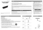
M176-LD(N)D45-001
HIGH PERFORMANCE
WDR DOME CAMERA
O PERATI O N M ANUAL
Thank you for choosing our high quality camera.
Before attempting to connect or operate this unit, please read and follow these instructions.
CONTENTS
1. CAUTIONS
2. IMPORTANT SAFETY INSTRUCTIONS
3. EQUIPMENT AND ACCESSORIES
4. CAMERA COMPONENT DESCRIPTIONS
5. INSTALLATION
6. DIMENSIONS
7. SPECIFICATIONS
8. OSD MANUAL
• Menu Structure
• Function Description
CAUTIO N
These servicing instructions are for use by qualified service personnel only.
To reduce the risk of electric shock, do not perform any servicing other than
that contained in the operating instructions unless you are qualified to do so.
Use Class 2 Power Supply Only
2
1. CAUTIONS
This device complies with Part 15 of the FCC Rules.
Operation is subject to the following two conditions:
1. This device may not cause harmful interference.
2. This device must accept any interference received, including
interference that may cause undesired operation.
Note
This equipment has been tested and found to comply with the limits for a Class A
digital device, pursuant to part 15 of the FCC Rules. These limits are designed to
provide reasonable protection against harmful interference when the equipment is
operated in a commercial environment. This equipment generates, uses, and can
radiate radio frequency energy and, if not installed and used in accordance with
the instruction manual, may cause harmful interference to radio communications.
Operation of this equipment in a residential area is likely to cause harmful
interference in which case the user will be required to correct the interference at his
own expense.
WARNING
This is a class A product. In a domestic environment this product may cause radio
interference in which case the user may be required to take adequate measures.
Caution
Any changes or modifications in construction of this devices which are not expressly
approved by the party responsible for compliance could void the user’s authority to
operate the equipment.
1. A regulated DC12V 500mA power supply is recommended for use with
this camera for the best picture and the most stable operation.
An unregulated power supply can cause damage to the camera.
When an unregulated power supply is applied, the product warranty will
be void.
2. It is recommended that the camera be used with a monitor that has a CCTV
quality 75 video impedance level. If your monitor is switched to high impedance
then please adjust accordingly.
3. Do not attempt to disassemble the camera to gain access to the internal
components. Refer servicing to your dealer.
4. Never face the camera towards the sun or any bright or reflective light, which
may cause smears on the picture and possible damage to the image sensor.
5. Do not remove the serial sticker for the warranty service.
6. Do not expose the camera to rain or other types of liquid.
7. The apparatus must be connected to a main socket-outlet with a protective
earth connection.
3
1. CAUTIONS
WEEE
(Waste Electrical & Electronic Equipment)
This marking shown on the product or its literature, indicates that it should not be
disposed with other household wastes at the end of its working life. To prevent
possible harm to the environment or human health from uncontrolled waste
disposal, please separate this from other types of wastes and recycle it responsibly
to promote the sustainable reuse of material resources. Household users
should contact either the retailer where they purchased this product, or their
local government office, for details of where and how they can take item for
environmentally safe recycling.
Business users should contact their supplier and check the terms and conditions of
the purchase contract.
This product should not be mixed with other commercial wastes for disposal.
CAUTION
RISK OF ELECTRIC SHOCK DO NOT OPEN
CAUTION: TO REDUCE THE RISK OF ELECTRIC SHOCK, DO NOT
REMOVE COVER (OR BACK). NO USER SERVICEABLE
PARTS INSIDE. REFER SERVICING TO QUALIFIED
SERVICE PERSONNEL
This symbol is intended to alert the user to the presence of uninsulated “dangerous voltage” within the product’s enclosure
that may be of sufficient magnitude to constitute a risk of
electric shock.
This symbol is intended to alert the user to the presence of
important operating and maintenance (servicing) instructions
in the literature accompanying the appliance.
4
2. IMPORTANT SAFETY INSTRUCTIONS
1) Read these instructions.
2) Keep these instructions.
3) Heed all warnings.
4) Follow all instructions.
5) Do not use this apparatus near water.
6) Clean only with dry cloth.
7) Do not block any ventilation openings. Install in accordance
with the manufacturer’s instructions.
8) Do not install near any heat sources such as radiators, heat registers,
stoves, or other apparatuses (including amplifiers) that produce heat.
9) Do not defeat the safety purpose of the polarized or grounding-type plug. A
polarized plug has two blades with one wider than the other. A grounding type plug
has two blades and a third grounding prong. The wide blade or the third prong are
provided for your safety. If the provided plug does not fit into your outlet, consult
an electrician for replacement of the obsolete outlet.
10) Protect the power cord from being walked on or pinched particularly at plugs,
convenience receptacles, and the point where it exits from the apparatus.
11) Only use attachments/accessories specified by the manufacturer.
12) Use only with the cart, stand, tripod, bracket, or table specified by
the manufacturer, or sold with the apparatus. When a cart is used,
use caution when moving the cart/apparatus combination to
avoid injury from tip-over.
13) Unplug this apparatus during lightning storms or when unused for long
periods of time.
14) Refer all servicing to qualified service personnel. Servicing is required when
the apparatus has been damaged in any way, such as when the power-supply
cord or plug is damaged, liquid has been spilled or objects have fallen into the
apparatus, or the apparatus has been exposed to rain or moisture, does not
operate normally, or has been dropped.
5
3. EQUIPMENT AND ACCESSORIES
+ -
Dome Type
Mount Guide
Manual
Screws(3ea) / L-Wrench
Service Video Output Test Cable
6
4. CAMERA COMPONENT DESCRIPTIONS
➊
➐
➑
➋
➌
➒
LED Type
Standard Type
➍
➓
➎
NO
PART NAME
1
Housing Top
2
Window
3
Cover PCB
4
PCB Module
5
Rubber Case
6
Housing Bottom
7
Holder Middle
8
➏
Holder Top
9
Ball Ass'y
10
Holder Bottom
11
Wave Water
7
5. INSTALLATION
1. Attach the Camera to the ceiling with using the screws provided, taking into considering the camera
angle required for the surveillance function.
Template
M4 Tappint Screw - 3EA
2. Adjust the LENS ANGLE to the desired location by hand.
Rotate: ±180°
Tilt:
LED Type: 0~75°
Standard Type: 0~90°
Pan: ±15°
Pan Rotation
Tilt Rotation
Horizontal Rotation
CAUTION: With certain wide-angle lenses, the upper part of the image may be obscured when
the tilt angle exceeds 80°
CAUTION: panning(Pan + Horizontal) the bracket in excess of 1 rotations in one direction may
cause damage to the cable.
8
5. INSTALLATION
3. Connect the VIDEO OUT CABLE and check the video image. Change the SETTINGS accordingly
using the OSD controller.
Controller
Test Video Connector
Video Output Test Cable
4. After the SETTING is completed, install the TOP COVER.
M4 Star Screw(T-20)
L-Wrench(T-20)
9
5. INSTALLATION
• MONITOR CONNECTION
- DC12V/AC24V
DC12V/AC24V
(TERMINAL BLOCK)
DC12V/AC24V
POWER SUPPLY
MONITOR
BNC FEMALE
VIDEO IN
CAMERA
DC12V ADAPTER
DC12V
(DC JACK)
- DC12V
MONITOR
BNC FEMALE
VIDEO IN
CAMERA
When you install the camera, please glue the end of cable to
keep it stable in order to protect the camera from humidity problems.
10
55
6. DIMENSIONS
Ø120
6
10
Ø
Unit(mm)
11
7. SPECIFICATIONS
Image Sensor
Scanning System
H Resolution.
Scanning Frequency
Total Pixels No.
LED Type
Standard Type
1/3” 960H SONY Double Scan Super HAD CCD II
2 : 1 Interlace
750TV Lines
NTSC: 15.734KHz(H), 59.94Hz(V) / PAL: 15.625KHz(H), 50Hz(V)
NTSC: 1028(H) X 508(V) / PAL: 1028(H) X 596(V)
Effective Pixels No.
NTSC: 976(H) X 494(V) / PAL: 976(H) X 582(V)
S/N Ratio
More than 50dB(3DNR ON)
Min. Illumination
Sync System
Gamma
0Lux
Video Output
1.0 Vp-p Composite(75Ω)
Lens
Digital Zoom Ratio
Electronic Shutter
Digital Slow Shutter
Flickerless
WDR
BLC
Board Lens
3x
NTSC: 1/60 ~1/100,000sec, PAL: 1/50 ~1/100,000sec
OFF, 2 ~ 256 Field
ON / OFF
ON / OFF (Level adjustable)
ON / OFF (Level adjustment, Area selection)
HLC
AGC
DNR(2D/3D)
ON / AUTO / OFF (Level adjustable)
OFF, 6 ~ 36dB
ON / OFF (Level adjustable)
Image Function
Image reverse(NORMAL/H / V / HV), Freeze, Contrast, Sharpness
True Day & Night With ICR Mechanism
COLOR / BW / AUTO
COLOR / BW / AUTO
850nm, 15ea
up to 15M
4 Zones (Level adjustable, Area adjustment)
15 Zones (Area adjustment)
Day & Night
IR LED
IR LED Distance
Motion Detection
Privacy Masking
ATW / PUSH / USER1 / USER2 / ANTI CR /
MANUAL / PUSH-LOCK
White Balance
OSD
Language
Operating Temperature
Storage Temperature
Humidity
DC
Power
Consumption
DUA L
Dimension (mm)
Weight
IP Rating
0.1Lux
Internal
r= 0.45
Built in (Joystick)
ENGLISH / JAPANESE / GERMAN / FRENCH /
RUSSIAN / PORTUGUESE / SPANISH / CHINESE
HINDI, TAMIL, TURKISH, ARABIC, FARSI
14°F~122°F(-10°C~+50°C)
-4°F~140°F(-20°C~+60°C)
Less than 80%
DC12V (±10%), Max. 250mA
DC12V (±10%), Max. 150mA
DC12V (±10%), Max. 340mA
DC12V (±10%), Max. 200mA
AC24V (±10%), Max. 4.0W
AC24V (±10%), Max. 2.5W
Ø120mm x 55mm
Approx. 350g
IP 66
Specifications and designs are subject to change for improving the
functionality of this product without notice.
12
8. OSD MANUAL
• Menu structure
Main MENU
1st Sub MENU 2nd Sub MENU
HIGH LUMINANCE
AUTO
EXPOSURE
SHUT
AGC
RETURN
SPEED
ATW
4th Sub MENU
FLICKERLESS
BRIGHTNESS
OFF / ON
0 ~ 255
OFF, AGC, SLOW, AGC->SLOW,
SLOW->AGC, AGC->SLOW->AGC
6, 12, 18, 24, 30, 36
2, 4, 8, 16, 32, 64, 128, 256
x0.25,x0.50,x0.75,x1.00
MODE
LOW LUMINANCE
RETURN
MODE
MANUAL
3rd Sub MENU
AGC MAX
DSS MAX
BRIGHTNESS
5th Sub MENU
SHUT, SLOW
MODE (SHUT) ONLY
1/50(PAL), 1/60(NTSC), 1/100(NTSC), 1/120(PAL),
1/250, 1/500, 1/1000, 1/2000, 1/4000, 1/10000, 1/50000, 1/100000
MODE (SLOW) ONLY 2, 4, 8, 16, 32, 64, 128, 256
6, 12, 18, 24, 30, 36, 42, 44.8
0 ~ 255
DELAY CNT
0 ~ 255
ATW FRAME
x0.5, x1.0, x1.5, x2.0
ENVIRONMENT
INDOOR, OUTDOOR
RETURN
PUSH
USER1
B-GAIN
0 ~ 255
R-GAIN
0 ~ 255
RETURN
WHITE
BALANCE
USER2
B-GAIN
0 ~ 255
R-GAIN
0 ~ 255
RETURN
ANTI CR
MANUAL
LEVEL UP
PUSH ENTER
LEVEL DOWN
PUSH ENTER
PRESET
RETURN
PUSH LOCK
COLOR
BURST
DELAY CNT
DAY > NIGHT
AUTO
NIGHT > DAY
IR OPTIMIZER
(LED TYPE)
DAY&NIGHT
RETURN
BURST
BW
IR OPTIMIZER
(LED TYPE)
RETURN
OFF, ON
0 ~ 15
(000 ~ 014) (LED TYPE)
(000 ~ 254)
(001 ~ 015) (LED TYPE)
(001 ~ 255)
MODE
ON
LEVEL
OFF
CENTER, AUTO
000 ~ 031
OFF, ON
MODE
LEVEL
ON
OFF
13
CENTER, AUTO
000 ~ 031
8. OSD MANUAL
Main MENU
1st Sub MENU
WDR MODE
2nd Sub MENU
ON
3rd Sub MENU
LEVEL
CONTRAST1
CONTRAST2
4th Sub MENU
0 ~ 15
0~7
0~4
BLC ZONE
LEVEL
CENTER, TOP, BOTTOM,
LEFT, RIGHT
0 ~ 254
CLIP LEVEL
SCALE
0 ~ 255
0 ~ 15
5th Sub MENU
OFF
WDR/BLC
BLC MODE
ON
OFF
HLC MODE
DNR
IMAGE
2DNR MODE
2DNR LEVEL
3DNR MODE
3DNR LEVEL
RETURN
MIRROR
FREEZE
EZOOM
CONTRAST
SHARPNESS
RETURN
CAMERA TITLE
LANGUAGE
PRIVACY
SPECIAL
MOTION DET
ON, AUTO
OFF
OFF, ON
0 ~ 15
OFF, ON
0 ~ 63
OFF, V-FLIP, H-FLIP, HV-FLIP
OFF, ON
1.0x ~ 3.0x
0 ~ 63
0 ~ 15
EDIT MODE
RETURN
OFF
ENGLISH / 中文 / Р у с с к и й / ESPAÑOL / DEUTSCH / FRANCAIS /
PORTUGUÊS / 日本語 / HINDI / TAMIL / TURKISH / ARABIC / FARSI
AREA SEL
1/15 ~ 15/15
MODE
OFF, ON
POSITION
PUSH ENTER
"WHITE, BLACK, RED, GREEN, BLUE,
COLOR
YELLOW, CYAN, MAGENTA"
TRANSP
0.00, 0.50, 0.75, 1.00
MOSAIC
OFF, ON
RETURN
DETECT SENSE 0 ~ 127
BLOCK DISP
OFF, ON
AREA SEL
1/4 ~ 4/4
MODE
OFF, ON
TOP
0 ~ 15
ON
0 ~ 15
MONITOR AREA BOTTOM
LEFT
0 ~ 23
RIGHT
0 ~ 23
RETURN
OFF
ON
RETURN
FACTORY
DEFAULT
EXIT
SAVE&EXIT
14