1
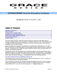
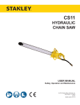
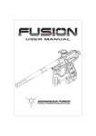
CR27
HYDRAULIC
CIRCULAR SAW
Safety, Operation and Maintenance
USER MANUAL
© 2011 Stanley Black & Decker, Inc.
New Britain, CT 06053
U.S.A.
30673 6/2012 Ver. 6
TABLE OF CONTENTS
SAFETY SYMBOLS...................................................................................................................................................4
SAFETY PRECAUTIONS...........................................................................................................................................5
ELECTRICAL HAZARDS...........................................................................................................................................7
TOOL STICKERS & TAGS.......................................................................................................................................10
HOSE TYPES........................................................................................................................................................... 11
HOSE RECOMMENDATIONS.................................................................................................................................12
FIGURE 1. TYPICAL HOSE CONNECTIONS......................................................................................................12
HTMA REQUIREMENTS..........................................................................................................................................13
OPERATION.............................................................................................................................................................14
FIGURE 2. CORRECT ROTATION DIRECTION..................................................................................................15
FIGURE 3. COLLET NUT & LOCKING NUT........................................................................................................15
FIGURE 4. FLUSH CUTTING A LIMB THAT MIGHT SPLIT OR TEAR................................................................ 16
FIGURE 5. FLUSH CUT........................................................................................................................................16
FIGURE 6. BLADE SHARPENING.......................................................................................................................17
FIGURE 7. FILING ANGLE...................................................................................................................................17
FIGURE 8. SETTING CUTTER TOOTH ANGLE..................................................................................................18
TOOL PROTECTION & CARE.................................................................................................................................19
TROUBLESHOOTING.............................................................................................................................................20
SPECIFICATIONS....................................................................................................................................................21
ACCESSORIES.......................................................................................................................................................21
CR27 PARTS ILLUSTRATION.................................................................................................................................22
CR27 PARTS LIST...................................................................................................................................................23
IMPORTANT
To fill out a Product Warranty Recording form, and for information on your warranty,
visit Stanleyhydraulic.com and select the Warranty tab.
(NOTE: The warranty recording form must be submitted to validate the warranty).
SERVICING: This manual contains safety, operation, and routine maintenance instructions. Stanley Hydraulic
Tools recommends that servicing of hydraulic tools, other than routine maintenance, must be performed by an authorized and certified dealer. Please read the following warning.
WARNING
SERIOUS INJURY OR DEATH COULD RESULT FROM THE IMPROPER REPAIR OR
SERVICE OF THIS TOOL.
REPAIRS AND / OR SERVICE TO THIS TOOL MUST ONLY BE DONE BY AN
AUTHORIZED AND CERTIFIED DEALER.
For the nearest authorized and certified dealer, call Stanley Hydraulic Tools at the number listed on the back of this
manual and ask for a Customer Service Representative.
CR27 User Manual ◄ 3
SAFETY SYMBOLS
Safety symbols and signal words, as shown below, are used to emphasize all operator, maintenance and repair actions which, if not strictly followed, could result in a life-threatening situation, bodily injury or damage to equipment.
This is the safety alert symbol. It is used to alert you to potential personal injury
hazards. Obey all safety messages that follow this symbol to avoid possible
injury or death.
DANGER
This safety alert and signal word indicate an imminently hazardous situation
which, if not avoided, will result in death or serious injury.
WARNING
This safety alert and signal word indicate a potentially hazardous situation
which, if not avoided, could result in death or serious injury.
CAUTION
This safety alert and signal word indicate a potentially hazardous situation
which, if not avoided, could result in death or serious injury.
CAUTION
This signal word indicates a potentially hazardous situation which, if not avoided, may result in property damage.
NOTICE
This signal word indicates a situation which, if not avoided, will result in damage
to the equipment.
IMPORTANT
This signal word indicates a situation which, if not avoided, may result in damage to the equipment.
Always observe safety symbols. They are included for your safety and for the protection of the tool.
LOCAL SAFETY REGULATIONS
Enter any local safety regulations here. Keep these instructions in an area accessible to the operator and maintenance personnel.
4 ► CR27 User Manual
SAFETY PRECAUTIONS
Tool operators and maintenance personnel must always
comply with the safety precautions given in this manual
and on the stickers and tags attached to the tool and
hose.
•
Do not operate the tool at oil temperatures above
140 °F/60 °C. Operation at higher oil temperatures
can cause operator discomfort and may damage the
tool.
These safety precautions are given for your safety. Review them carefully before operating the tool and before
performing general maintenance or repairs.
•
To avoid personal injury or equipment damage, all
tool repair, maintenance and service must only be
performed by authorized and properly trained personnel.
•
Do not exceed the rated limits of the tool or use the
tool for applications beyond its design capacity.
•
Always keep critical tool markings, such as labels
and warning stickers legible.
•
Always replace parts with replacement parts recommended by Stanley Hydraulic Tools.
•
Check fastener tightness often and before each use
daily.
•
Do not wear loose fitting clothing when operating the
tool.
•
Keep all parts of your body away from the rotating
saw blade.
•
Keep the saw blade off all surfaces when starting
the circle saw.
•
Do not reverse saw blade rotation direction by
changing fluid flow direction.
•
Without the use of non-conductive accessories, this
tool is not for use near energized electric lines. Failure to comply with this warning could result in serious personal injury.
•
Never cock, jam or wedge the saw blade during operation.
•
Eye injury and cutting or severing of body parts is
possible if proper procedures are not followed.
Supervising personnel should develop additional precautions relating to the specific work area and local
safety regulations. If so, place the added precautions in
the space provided in this manual.
The CR27 Hydraulic Circular Saw will provide safe and
dependable service if operated in accordance with the
instructions given in this manual. Read and understand
this manual and any stickers and tags attached to the
tool and hoses before operation. Failure to do so could
result in personal injury or equipment damage.
•
Operator must start in a work area without bystanders. The operator must be familiar with all prohibited
work areas such as excessive slopes and dangerous terrain conditions.
•
Establish a training program for all operators to ensure safe operation.
•
Do not operate the tool unless thoroughly trained or
under the supervision of an instructor.
•
Always wear safety equipment such as goggles,
ear, head protection, and safety shoes at all times
when operating the tool.
•
Do not overreach. Maintain proper footing and balance at all times.
•
Do not inspect or clean the tool while the hydraulic
power source is connected. Accidental engagement
of the tool can cause serious injury.
•
Supply hoses must have a minimum working pressure rating of 2500 psi/175 bar.
•
Be sure all hose connections are tight.
•
The hydraulic circuit control valve must be in the
OFF position when coupling or uncoupling the tool.
Wipe all couplers clean before connecting. Use only
lint-free cloths. Failure to do so may result in damage to the quick couplers and cause overheating of
the hydraulic system.
•
Do not operate a damaged, improperly adjusted, or
incompletely assembled tool.
CIRCULAR SAW SPECIFIC SAFETY
PRECAUTIONS
•
Do not rely exclusively upon the safety devices built
into the saw. As a circle saw user, several steps
must be taken to keep your cutting jobs free from
accident or injury.
•
Ensure the saw blade is correctly mounted and
tightened before each use.
•
Keep a good firm grip on the pole saw with both
hands. Place your right hand on the rear handle and
your left hand on the outer tube assembly when operating. Use a firm grip with your thumbs and fingers
encircling the saw handle and outer tube assembly.
A firm grip helps keep control of the saw. Do not let
go.
CR27 User Manual ◄ 5
SAFETY PRECAUTIONS
•
Ensure that the direction of rotation of the saw blade
is as prescribed in this manual.
•
Cut at the rated operating speeds (gpm).
•
Operate the saw at “no load” for 30 seconds in a
safe position and ensure there is no excessive vibration or other defects detected. If considerable vibration or other defects are detected, stop operation
of the tool immediately and determine the cause. Do
not use the tool until the defect is corrected.
•
Use extreme caution when cutting small branches.
Twigs may catch the saw blade and be whipped toward the operator or pull the operator off balance.
•
Only use saw blades manufactured by Stanley Hydraulic Tools. Stanley assumes no responsibility for
failure in equipment, accidental damage or accidental injury as a result of the use of saw blades not
manufactured by Stanley Hydraulic Tools.
•
Always assure the saw blade is sharp. Do not try to
use the tool with a dull saw blade.
•
If the tool is dropped with a saw blade installed, the
saw blade should be examined.
•
•
Make sure you’re well rested and mentally alert before operating the saw.
Keep the handle dry, clean and free of hydraulic
fluid.
•
•
Do not start cutting until you have a clear work area,
secure footing and a planned drop area for falling
branches.
When using tools near energized transmission lines,
make sure to use only hoses labeled and certified
non-conductive.
•
•
Keep all parts of the body away from the saw during
operation.
Turn off the power unit or move the hydraulic control
valve to neutral before setting the pole saw down.
•
•
Carry the saw with the unit de-energized.
Know the location of buried or covered electrical
services before starting work.
•
Do not operate a pole saw that is damaged, improperly adjusted or not completely and securely assembled. Make sure the saw blade stops moving when
the control trigger is released.
•
To avoid personal injury or equipment damage, all
tool repair, maintenance and service must only be
performed by authorized and properly trained personnel.
6 ► CR27 User Manual
ELECTRICAL HAZARDS
The following guidelines must be followed to prevent
accidental contact with overhead electrical conductors
and/or communication wires and cables. (Ref. ANSI
Z133.1-1982)
All overhead conductors and all communications wires
and cables are considered to be energized with potentially fatal voltages and must never be touched either directly or indirectly. Accidental contact with any overhead
conductors or communication wires and cables can result in death or serious injury.
A close inspection shall be made by the tool operator and by the tool operator’s supervisor to determine
whether an electrical conductor passes through the tree
or passes within reaching distance of the tool operator.
Only qualified tool operators shall be assigned to the
work if an electrical hazard exists.
A second qualified tool operator must be within normal
voice communication during line clearing operations
aloft when the tool operator approaches closer than 10
feet (3 m) to any conductor or electrical apparatus energized in excess of 750 volts, or when roping is required
to remove the branches or limbs.
Tool operators must maintain the following clearances
from energized conductors:
Voltage Range
(phase-to-phase) (kV)
Minimum Working
Distance
2.1–15.0
2 ft 0 in./0.6 m
15.1–35.0
2 ft 4 in./0.7 m
35.1–46.0
2 ft 6 in./0.75 m
46.1–72.5
3 ft 0 in./0.9 m
72.6–121.0
3 ft 4 in./1.0 m
138.0–145.0
3 ft 6 in./1.05 m
161.0–169.0
3 ft 8 in./1.1 m
230.0–242.0
5 ft 0 in./1.5 m
345.0–362.0
7 ft 0 in./2.1 m
500.0–552.0
11 ft 0 in./3.35 m
700.0–765.0
15 ft 0 in./4.55 m
All other tree workers must maintain a minimum clearance of 10 feet (3 meters) from energized conductors
rated 50 kV phase-to-phase or less. Conductors rated
over 50 kV phase-to-phase require a minimum clearance of 10 feet plus 4/10 of an inch (3 meters plus 10
mm) for each kilovolt over 50 kV.
When a lifting device contacts an electrical conductor,
the truck supporting the device is considered to be energized and contact with the truck must be avoided except
when emergency rescue procedures are being carried
out. Emergency rescue should only be attempted by
properly trained personnel familiar with electrical hazards.
Storm work and emergency conditions create special
hazards. During these conditions, only authorized tool
operators shall perform any tree operation.The following guidelines must be followed to prevent accidental
contact with overhead electrical conductors and/or communication wires and cables. (Ref. ANSI Z133.1-2000)
Working in Proximity to Electrical Hazards:
An inspection shall be made by a qualified arborist to
determine whether an electrical hazard exists before
climbing, or otherwise entering, or performing work in
or on a tree.
Only qualified line-clearance arborists or qualified lineclearance arborist trainees shall be assigned to work
where an electrical hazard exists. Qualified line-clearance arborist trainees shall be under the direct supervision of qualified line-clearance arborist.
A second qualified line-clearance arborists or line-clearance arborist trainees shall be within vision or voice
communication during line-clearing operations aloft
when line-clearance arborists or line-clearance arborist
trainees must approach closer than 10 feet (3.05 meters) to any energized electrical conductor in excess of
750 volts (primary conductor) or when:
1. Branches or limbs being removed cannot first be
cut (with a pole pruner/pole saw) to sufficiently clear
electrical conductors, so as to avoid contact.
2. Roping is required to remove branches or limbs
from such electrical conductors. This does not apply to individuals working on behalf of, or employed
by, electrical system owners/operators engaged in
line-clearing operations incidental to their normal
occupation.
Qualified line-clearance arborists and line-clearance
arborist trainees shall maintain minimum approach distances from energized electrical conductors in accordance with Table 1.
All other arborists shall maintain a minimum approach
distance from energized electrical conductors in accordance with Table 2.
Branches hanging on an energized electrical conductor
shall be removed using non-conductive equipment.
CR27 User Manual ◄ 7
ELECTRICAL HAZARDS
Table 1. Minimum approach distances from energized conductors for qualified line-clearance arborists and
qualified line-clearance arborist trainees.
Nominal
Voltage
kV phase-to-phase
Includes 1910.269
elevation factor, sea
level to 5000 ft1)
ft-in
0.05–1.0
Includes 1910.269
elevation factor,
5001–10,000 ft1)
m
ft-in
Avoid contact
m
Includes 1910.269
elevation factor,
10,000–14,000 ft1)
ft-in
Avoid contact
m
Avoid contact
1.1–15.0
2-04
0.71
2-08
0.81
2-10
0.86
15.1–36.0
2-09
0.84
3-02
0.97
3-05
1.04
36.1–46.0
3-00
0.92
3-05
1.04
3-09
1.14
46.1–72.5
3-09
1.14
4-03
1.30
4-07
1.40
72.6–121.0
4-06
1.37
5-02
1.58
5-07
1.70
138.0–145.0
5-02
1.58
5-11
1.80
6-05
1.96
161.0–169.0
6-00
1.83
6-10
2.08
7-05
2.26
230.0–242.0
7-11
2.41
9-00
2.75
9-09
2.97
345.0–362.0
13-02
4.02
15-00
4.58
16-03
4.96
500.0–550.0
19-00
5.80
21-09
6.63
23-06
7.17
765.0–800.0
27-04
8.34
31-03
9.53
33-10
10.32
1)
Exceeds phase-to-ground; elevation factor per 29 CFR 1910.269.
Table 2. Minimum approach distances to energized conductors for persons other than qualified line-clearance arborists and qualified line-clearance arborist trainees.
Nominal Voltage
kV phase-to-phase1)
Distance
ft-in
m
0.0–1.0
10-00
3.05
1.1–15.0
10-00
3.05
15.1–36.0
10-00
3.05
36.1–50.0
10-00
3.05
50.1–72.5
10-09
3.28
72.6–121.0
12-04
3.76
138.0–145.0
13-02
4.00
161.0–169.0
14-00
4.24
230.0–242.0
16-05
4.97
345.0–362.0
20-05
6.17
500.0–550.0
26-08
8.05
785.0–800.0
35-00
10.55
1)
Exceeds phase-to-ground.
8 ► CR27 User Manual
ELECTRICAL HAZARDS
The tie-in position should be above the work area and
located in such a way that a slip would swing the arborist
away from any energized electrical conductors or other
identified hazard.
While climbing, the arborist should climb on the side of
the tree that is away from energized electrical conductors as required in Tables 1 and 2.
Footwear, including lineman’s overshoes, having electrical-resistant soles, shall not be considered as providing
any measure of safety from electrical hazards.
Rubber gloves, with or without leather or other protective covering, shall not be considered as providing any
measure of safety from electrical hazards.
Ladders, platforms and aerial devices, including insulated aerial devices, shall be subject to minimum approach
distances in Table 1 and 2.
STORM WORK AND EMERGENCY
CONDITIONS-LINE CLEARANCE
Line clearance shall not be performed during adverse
weather conditions such as thunderstorms, high winds
and snow and ice storms.
Qualified line-clearance arborists and qualified lineclearance arborists trainees performing line clearance
in the aftermath of a storm or under similar conditions
shall be trained in the special hazards associated with
this type of work.
Line-clearance operations shall be suspended when
storm work or emergency conditions develop involving
energized electrical conductors. Electrical system owners/operators shall be notified immediately.
Aerial devices and attached equipment (such as chippers) contacting energized electrical conductors shall be
considered energized. Contact shall be avoided, except
where emergency rescue procedures are being carried
out. Emergency rescue should be performed in accordance with 4.3.
CR27 User Manual ◄ 9
TOOL STICKERS & TAGS
DANGER
DANGER
THIS SAW BLADE OF THE CR27 WILL CONTINUE TO ROTATE
FOR UP TO 15 SECONDS OR MORE AFTER RELEASING THE
ON/OFF TRIGGER. DURING THIS “COAST DOWN” TIME,
CONTACT WITH THE BLADE OF THE CR27 MAY RESULT IN
SEVERE PERSONAL INJURY.
AFTER RELEASING THE ON/OFF TRIGGER, SAW OPERATORS
MUST BE CERTAIN THAT THE BLADE HAS COME TO A COMPLETE
STOP BEFORE PLACING THE SAW ON THE GROUND, LOWERING
THE SAW INTO THE TRUCKS BUCKET, STORING THE SAW OR
CONTACTING THE BLADE IN ANY WAY. FAILURE TO OBSERVE
THESE PRECAUTIONS MAY RESULT IN SEVERE PERSONAL
INJURY.
Failure to use hydraulic hose labeled and certified
as non-conductive when using hydraulic tools on
or near electric lines may result in death or
serious injury.
For proper and safe operation read owners manual
and mwke sure that you have been properly
ELECTROCUTION
HAZARD
trained in correct procedures required for work
on or around electric lines.
12412
Electrical Warning Decal
15863
Danger Decal
OTHER WORKERS AND BYSTANDERS MUST STAY CLEAR OF
THE WORK AREA TO AVOID SEVERE PERSONAL INJURY RESULTING
FROM CONTACT WITH THE SAW BLADE AS WELL AS FALLING
LIMBS, BRANCHES AND OTHER DEBRIS.
27694
Danger Decal
Stanley Hydraulic Tools
3810 SENaef Road
Milwaukie, OR 97062
Model
05153
Stanley Decal
03784
5-7 GPM Sticker
24827
Name Tag
D A N G E R
1.
FAILURE TO USE HYDRAULIC HOSE LABELED AND CERTIFIED AS NON-CONDUCTIVE WHEN USING HYDRAULIC
TOOLS ON OR NEAR ELECTRICAL LINES MAY RESULT IN
DEATH OR SERIOUS INJURY.
BEFORE USING HOSE LABELED AND CERTIFIED AS NONCONDUCTIVE ON OR NEAR ELECTRIC LINES BE SURE THE
HOSE IS MAINTAINED AS NON-CONDUCTIVE. THE HOSE
SHOULD BE REGULARLY TESTED FOR ELECTRIC CURRENT LEAKAGE IN ACCORDANCE WITH YOUR SAFETY
DEPARTMENT INSTRUCTIONS.
2.
A HYDRAULIC LEAK OR BURST MAY CAUSE OIL INJECTION INTO THE BODY OR CAUSE OTHER SEVERE
PERSONAL INJURY.
A.
DO NOT EXCEED SPECIFIED FLOW AND PRESSURE
FOR THIS TOOL. EXCESS FLOW OR PRESSURE MAY
CAUSE A LEAK OR BURST.
B.
DO NOT EXCEED RATED WORKING PRESSURE OF
HYDRAULIC HOSE USED WITH THIS TOOL. EXCESS
PRESSURE MAY CAUSE A LEAK OR BURST.
C. CHECK TOOL HOSE COUPLERS AND CONNECTORS
DAILY FOR LEAKS. DO NOT FEEL FOR LEAKS WITH
YOUR HANDS. CONTACT WITH A LEAK MAY RESULT
IN SEVERE PERSONAL INJURY.
D A N G E R
D. DO NOT LIFT OR CARRY TOOL BY THE HOSES. DO
NOT ABUSE HOSE. DO NOT USE KINKED, TORN OR
DAMAGED HOSE.
3.
MAKE SURE HYDRAULIC HOSES ARE PROPERLY CONNECTED TO THE TOOL BEFORE PRESSURING SYSTEM.
SYSTEM PRESSURE HOSE MUST ALWAYS BE CONNECTED TO TOOL “IN” PORT. SYSTEM RETURN HOSE
MUST ALWAYS BE CONNECTED TO TOOL “OUT” PORT.
REVERSING CONNECTIONS MAY CAUSE REVERSE
TOOL OPERATION WHICH CAN RESULT IN SEVERE
PERSONAL INJURY.
4.
DO NOT CONNECT OPEN-CENTER TOOLS TO CLOSEDCENTER HYDRAULIC SYSTEMS. THIS MAY RESULT IN
LOSS OF OTHER HYDRAULIC FUNCTIONS POWERED BY
THE SAME SYSTEM AND/OR SEVERE PERSONAL INJURY.
5.
BYSTANDERS MAY BE INJURED IN YOUR WORK AREA.
KEEP BYSTANDERS CLEAR OF YOUR WORK AREA.
6.
WEAR HEARING, EYE, FOOT, HAND AND HEAD PROTECTION.
7.
TO AVOID PERSONAL INJURY OR EQUIPMENT DAMAGE,
ALL TOOL REPAIR MAINTENANCE AND SERVICE MUST
ONLY BE PERFORMED BY AUTHORIZED AND PROPERLY
TRAINED PERSONNEL.
I M P O R T A N T
I M P O R T A N T
READ OPERATION MANUAL AND
SAFETY INSTRUCTIONS FOR THIS
TOOL BEFORE USING IT.
READ OPERATION MANUAL AND
SAFETY INSTRUCTIONS FOR THIS
TOOL BEFORE USING IT.
USE ONLY PARTS AND REPAIR
PROCEDURES APPROVED BY
STANLEY AND DESCRIBED IN THE
OPERATION MANUAL.
USE ONLY PARTS AND REPAIR
PROCEDURES APPROVED BY
STANLEY AND DESCRIBED IN THE
OPERATION MANUAL.
TAG TO BE REMOVED ONLY BY
TOOL OPERATOR.
TAG TO BE REMOVED ONLY BY
TOOL OPERATOR.
SEE OTHER SIDE
SEE OTHER SIDE
SAFETY TAG P/N 15875 (Shown smaller then actual size)
10 ► CR27 User Manual
HOSE TYPES
The rated working pressure of the hydraulic hose must be equal to or higher than the relief valve setting on the hydraulic system. There are three types of hydraulic hose that meet this requirement and are authorized for use with
Stanley Hydraulic Tools. They are:
Certified non-conductive — constructed of thermoplastic or synthetic rubber inner tube, synthetic fiber braid
reinforcement, and weather resistant thermoplastic or synthetic rubber cover. Hose labeled certified nonconductive is the only hose authorized for use near electrical conductors.
Wire-braided (conductive) — constructed of synthetic rubber inner tube, single or double wire braid reinforcement, and weather resistant synthetic rubber cover. This hose is conductive and must never be used near
electrical conductors.
Fabric-braided (not certified or labeled non-conductive) — constructed of thermoplastic or synthetic rubber inner tube, synthetic fiber braid reinforcement, and weather resistant thermoplastic or synthetic rubber cover. This
hose is not certified non-conductive and must never be used near electrical conductors.
HOSE SAFETY TAGS
To help ensure your safety, the following DANGER tags are attached to all hose purchased from Stanley Hydraulic
Tools. DO NOT REMOVE THESE TAGS.
If the information on a tag is illegible because of wear or damage, replace the tag immediately. A new tag may be
obtained from your Stanley Distributor.
D A N G E R
D A N G E R
1.
FAILURE TO USE HYDRAULIC HOSE LABELED AND CERTIFIED AS NON-CONDUCTIVE
WHEN USING HYDRAULIC TOOLS ON OR NEAR ELECTRIC LINES MAY RESULT IN
DEATH OR SERIOUS INJURY.
FOR PROPER AND SAFE OPERATION MAKE SURE THAT YOU HAVE BEEN PROPERLY TRAINED IN CORRECT PROCEDURES REQUIRED FOR WORK ON OR AROUND
ELECTRIC LINES.
2.
BEFORE USING HYDRAULIC HOSE LABELED AND CERTIFIED AS NON-CONDUCTIVE
ON OR NEAR ELECTRIC LINES. WIPE THE ENTIRE LENGTH OF THE HOSE AND FITTING WITH A CLEAN DRY ABSORBENT CLOTH TO REMOVE DIRT AND MOISTURE AND
TEST HOSE FOR MAXIMUM ALLOWABLE CURRENT LEAKAGE IN ACCORDANCE WITH
SAFETY DEPARTMENT INSTRUCTIONS.
3.
DO NOT EXCEED HOSE WORKING PRESSURE OR ABUSE HOSE. IMPROPER USE
OR HANDLING OF HOSE COULD RESULT IN BURST OR OTHER HOSE FAILURE.
KEEP HOSE AS FAR AWAY AS POSSIBLE FROM BODY AND DO NOT PERMIT DIRECT
CONTACT DURING USE. CONTACT AT THE BURST CAN CAUSE BODILY INJECTION
AND SEVERE PERSONAL INJURY.
4.
HANDLE AND ROUTE HOSE CAREFULLY TO AVOID KINKING, ABRASION, CUTTING, OR
CONTACT WITH HIGH TEMPERATURE SURFACES. DO NOT USE IF KINKED. DO NOT
USE HOSE TO PULL OR LIFT TOOLS, POWER UNITS, ETC.
5.
CHECK ENTIRE HOSE FOR CUTS CRACKS LEAKS ABRASIONS, BULGES, OR DAMAGE TO COUPLINGS IF ANY OF THESE CONDITIONS EXIST, REPLACE THE HOSE
IMMEDIATELY. NEVER USE TAPE OR ANY DEVICE TO ATTEMPT TO MEND THE HOSE.
6.
AFTER EACH USE STORE IN A CLEAN DRY AREA.
SEE OTHER SIDE
SIDE 1
SEE OTHER SIDE
(Shown smaller than actual size)
DO NOT REMOVE THIS TAG
DO NOT REMOVE THIS TAG
THE TAG SHOWN BELOW IS ATTACHED TO “CERTIFIED NON-CONDUCTIVE” HOSE
SIDE 2
D A N G E R
D A N G E R
1.
DO NOT USE THIS HYDRAULIC HOSE ON OR NEAR ELECTRIC LINES. THIS HOSE IS
NOT LABELED OR CERTIFIED AS NON-CONDUCTIVE. USING THIS HOSE ON OR NEAR
ELECTRICAL LINES MAY RESULT IN DEATH OR SERIOUS INJURY.
5.
CHECK ENTIRE HOSE FOR CUTS CRACKS LEAKS ABRASIONS, BULGES, OR DAMAGE TO
COUPLINGS IF ANY OF THESE CONDITIONS EXIST, REPLACE THE HOSE IMMEDIATELY.
NEVER USE TAPE OR ANY DEVICE TO ATTEMPT TO MEND THE HOSE.
2.
FOR PROPER AND SAFE OPERATION MAKE SURE THAT YOU HAVE BEEN PROPERLY
TRAINED IN CORRECT PROCEDURES REQUIRED FOR WORK ON OR AROUND ELECTRIC LINES.
6.
AFTER EACH USE STORE IN A CLEAN DRY AREA.
3.
DO NOT EXCEED HOSE WORKING PRESSURE OR ABUSE HOSE. IMPROPER USE OR
HANDLING OF HOSE COULD RESULT IN BURST OR OTHER HOSE FAILURE. KEEP HOSE
AS FAR AWAY AS POSSIBLE FROM BODY AND DO NOT PERMIT DIRECT CONTACT
DURING USE. CONTACT AT THE BURST CAN CAUSE BODILY INJECTION AND SEVERE
PERSONAL INJURY.
4.
HANDLE AND ROUTE HOSE CAREFULLY TO AVOID KINKING, CUTTING, OR CONTACT
WITH HIGH TEMPERATURE SURFACES. DO NOT USE IF KINKED. DO NOT USE HOSE TO
PULL OR LIFT TOOLS, POWER UNITS, ETC.
DO NOT REMOVE THIS TAG
DO NOT REMOVE THIS TAG
THE TAG SHOWN BELOW IS ATTACHED TO “CONDUCTIVE” HOSE.
SEE OTHER SIDE
SEE OTHER SIDE
SIDE 1
SIDE 2
(Shown smaller than actual size)
CR27 User Manual ◄ 11
12 ► CR27 User Manual
All hydraulic hose must meet or exceed
specifications as set forth by SAE J517.
All hydraulic hose must have at least a rated
minimum working pressure equal to the maximum hydraulic system relief valve setting.
This chart is intended to be used for hydraulic
tool applications only based on Stanley Hydraulic Tools tool operating requirements and
should not be used for any other applications.
The chart to the right shows recommended
minimum hose diameters for various hose
lengths based on gallons per minute (gpm)/
liters per minute (lpm). These recommendations are intended to keep return line pressure
(back pressure) to a minimum acceptable level to ensure maximum tool performance.
Tool to Hydraulic Circuit Hose
Recommendations
15-34
MM
Inside Diameter
INCH
USE
(Press/Return)
PSI
up to 10
up to 3
3/8
10
Both
2250
49-60
13-16
FLOW >>>
RETURN
<<< FLOW
PRESSURE
26-100
up to 25
100-200
51-100
up to 50
100-300
51-100
up to 50
26-100
up to 25
8-30
up to 8
30-60
15-30
up to 15
30-90
15-30
up to 15
7.5-30
up to 7.5
Figure 1. Typical Hose Connections
49-60
38-49
10-13
13-16
19-40
5-10.5
38-49
19-40
5-10.5
10-13
19-40
5-10.5
38-49
15-23
10-13
15-23
4-6
19
25.4
16
19
19
25.4
5/8
3/4
3/4
1
19
3/4
1
16
3/4
16
19
3/4
5/8
16
5/8
5/8
16
13
13
10
5/8
1/2
1/2
3/8
Return
Pressure
Return
Pressure
Return
Pressure
Return
Pressure
Both
Return
Pressure
Both
Both
Both
Both
2500
2500
2500
2500
2500
2500
2500
2500
2500
2500
2500
2500
2500
2500
2500
175
175
175
175
175
175
175
175
175
175
175
175
175
175
175
155
BAR
Min. Working Pressure
Certified Non-Conductive Hose - Fiber Braid - for Utility Bucket Trucks
METERS
Hose Lengths
FEET
Conductive Hose - Wire Braid or Fiber Braid -DO NOT USE NEAR ELECTRICAL CONDUCTORS
4-6
4-9
LPM
Oil Flow
GPM
HOSE RECOMMENDATIONS
HTMA REQUIREMENTS
HTMA / EHTMA REQUIREMENTS
HTMA
HYDRAULIC SYSTEM REQUIREMENTS
TYPE I
Nominal Operating Pressure
(at the power supply outlet)
4-6 gpm
(15-23 lpm)
1500 psi
(103 bar)
TOOL TYPE
TYPE II
TYPE RR
7-9 gpm
(26-34 lpm)
1500 psi
(103 bar)
9-10.5 gpm
(34-40 lpm)
1500 psi
(103 bar)
System relief valve setting
(at the power supply outlet)
2100-2250 psi
(145-155 bar)
2100-2250 psi
(145-155 bar)
2200-2300 psi
(152-159 bar)
2100-2250 psi
(145-155 bar)
Maximum back pressure
(at tool end of the return hose)
250 psi
(17 bar)
250 psi
(17 bar)
250 psi
(17 bar)
250 psi
(17 bar)
Measured at a max. fluid viscosity of:
(at min. operating temperature)
400 ssu*
400 ssu*
400 ssu*
400 ssu*
(82 centistokes) (82 centistokes) (82 centistokes) (82 centistokes)
Temperature: Sufficient heat rejection
capacity to limit max. fluid temperature to:
(at max. expected ambient temperature)
140° F
(60° C)
Flow Range
140° F
(60° C)
TYPE III
11-13 gpm
(42-49 lpm)
1500 psi
(103 bar)
140° F
(60° C)
140° F
(60° C)
3 hp
5 hp
6 hp
7 hp
Min. cooling capacity at a temperature
(2.24 kW)
(3.73 kW)
(5.22 kW)
(4.47 kW)
difference of between ambient and fluid
40° F
40° F
40° F
40° F
temps
(22° C)
(22° C)
(22° C)
(22° C)
NOTE:
Do not operate the tool at oil temperatures above 140° F (60° C). Operation at higher temperatures can cause operator
discomfort at the tool.
Filter
Min. full-flow filtration
Sized for flow of at least:
(For cold temp. startup and max.
dirt-holding capacity)
25 microns
30 gpm
(114 lpm)
Hydraulic fluid Petroleum based
(premium grade, anti-wear, non-conductive)
Viscosity (at min. and max. operating temps)
100-400 ssu*
25 microns
30 gpm
(114 lpm)
25 microns
30 gpm
(114 lpm)
25 microns
30 gpm
(114 lpm)
100-400 ssu*
100-400 ssu*
(20-82 centistokes)
100-400 ssu*
NOTE:
When choosing hydraulic fluid, the expected oil temperature extremes that will be experienced in service determine the
most suitable temperature viscosity characteristics. Hydraulic fluids with a viscosity index over 140 will meet the requirements
over a wide range of operating temperatures.
*SSU = Saybolt Seconds Universal
EHTMA
HYDRAULIC SYSTEM
REQUIREMENTS
CLASSIFICATION
B
C
D
Nominal Operating Pressure
(at the power supply outlet)
3.5-4.3 gpm
(13.5-16.5 lpm)
1870 psi
(129 bar)
4.7-5.8 gpm
(18-22 lpm)
1500 psi
(103 bar)
7.1-8.7 gpm
(27-33 lpm)
1500 psi
(103 bar)
9.5-11.6 gpm
(36-44 lpm)
1500 psi
(103 bar)
11.8-14.5 gpm
(45-55 lpm)
1500 psi
(103 bar)
System relief valve setting
(at the power supply outlet)
2495 psi
(172 bar)
2000 psi
(138 bar)
2000 psi
(138 bar)
2000 psi
(138 bar)
2000 psi
(138 bar)
Flow Range
NOTE: These are general hydraulic system requirements. See tool specification page for tool specific requirements
CR27 User Manual ◄ 13
OPERATION
PREOPERATION PROCEDURES
PREPARATION FOR INITIAL USE
Each unit as shipped has no special unpacking or assembly requirements prior to usage. Inspection to assure the unit was not damaged in shipping and does not
contain packing debris is all that is required. After installation of a saw blade a unit may be put to use.
CHECK HYDRAULIC POWER SOURCE
1. Using a calibrated flowmeter and pressure gauge,
check that the hydraulic power source develops a
flow of 5–7 gpm/19–26 lpm at 1000–2000 psi/70–
140 bar.
2. Make certain the hydraulic power source is equipped
with a relief valve set to open at 2100–2250 psi/145–
155 bar minimum.
3. Check that the dual spool valve is set to the hydraulic system type (open-center (OC) or closed-center
(CC) operation).
CHECK TOOL
1. Make sure all tool accessories are correctly installed. Failure to install tool accessories properly
can result in damage to the tool or personal injury.
2. There should be no signs of leaks.
3. The tool should be clean, with all fittings and fasteners tight.
CHECK TRIGGER MECHANISM
Check that the trigger operates smoothly and is free to
travel between the ON and OFF positions.
SETTING THE DUAL SPOOL FOR OC
(OPEN-CENTER) OR CC (CLOSEDCENTER) OPERATION
IMPORTANT
This tool is furnished with a ON/OFF spool
commonly referred to as a “dual spool” which permits
adjustment so the tool may be operated on either an
open-center (OC) or closed-center (CC) hydraulic
system. The dual spool is normally set to the OC
position at time of manufacture. The dual spool can
also be disabled so that the tool may be set to OC
only operation. For more details, please refer to the
following instructions.
14 ► CR27 User Manual
SETTING FOR OPEN-CENTER (OC) OR
CLOSED-CENTER (CC) OPERATION
1. To set the tool for open-center (OC) system operation turn the selector screw located in the top of the
valve spool fully out (counter-clockwise) until it hits
the stop.
2. To set the tool for closed-center (CC) system operation turn the selector screw located in the top of the
valve spool fully in (clockwise) until it bottoms.
TO DISABLE DUAL SPOOL OPERATION
AND CONVERT TO OPEN-CENTER ONLY
OPERATION
1. Turn the selector screw located in the top of the
valve spool fully out (counter-clockwise) until it hits
the stop.
2. Insert the small plug from the kit (furnished with the
tool) into the hole located in the top of the selector
screw. Tap the plug down using a small punch and
hammer. DO NOT USE ANY ADHESIVES.
TO DISABLE DUAL SPOOL OPERATION
AND CONVERT TO CLOSED-CENTER
ONLY OPERATION
1. Turn the selector screw located in the top of the
valve spool fully in (clockwise) until it bottoms.
2. Insert the small plug from the kit (furnished with the
tool) into the hole located in the top of the selector
screw. Tap the plug down using a small punch and
hammer. DO NOT USE ANY ADHESIVES.
BLADE INSTALLATION
1. Handle the saw blade with care. The cutting edges
are sharp and careless handling could result in injury.
2. Install the blade over the motor shaft and onto the
fixed collar so that the points of the teeth on the
blade are facing clockwise as viewed from the front
of the motor (see Figure 2).
3. Install the moveable collar followed by the collet nut
(see Figure 3). Tighten the collet nut hard (not wrist
tight).
4. Install the locking nut with internal taper facing toward the collet nut and tighten it hard against the
collet nut.
5. As a final tightening procedure, with a wrench on
each of the nuts, tighten the locking nut one half
wrench flat further.
Observe all safety precautions.
4. Install the locking nut with internal taper facing toward
5. As
a finut
nal and
tightening
withthe
a wrench
on each
the
collet
tightenprocedure,
it hard against
collet nut.
of the nuts, tighten the locking nut one half wrench flat
further.
5.
As a final tightening procedure, with a wrench on each
of the nuts, tighten the locking nut one half wrench flat
further.
CLOCKWISE ROTATION
CLOCKWISE ROTATION
Figure 1. Correct Rotation Direction
Figure
RotationDirection
Direction
Figure2.
1. Correct
Correct Rotation
COLLET NUT
COLLET NUT
LOCKING NUT
OPERATING PROCEDURES
DO NOT
OPERATE
A CIRCLE SAW UNLESS YOU HAVE
Observe
all safety
precautions.
BEEN SPECIFICALLY TRAINED TO DO SO.
OPERATION
DO NOT OPERATE A CIRCLE SAW UNLESS YOU HAVE
Keep
all parts of theTRAINED
body away
from
BEEN
SPECIFICALLY
TO
DO the
SO.saw blade during
operation of the tool.
Keep all parts of the body away from the saw blade during
Carry
the
sawtool.
withthe
thehoses
unit de-energized
and couplers
the blade
•
Always
to the tool hose
operation
of connect
the
away
from
the body.the power source.
before
energizing
Carry the saw with the unit de-energized and the blade
•
Do not operate a circle saw that is damaged, imAlways
away
from connect
the body.the hoses to the tool hose couplers before
properly adjusted or is not completely and securely
energizing the power source.
assembled.
Always connect the hoses to the tool hose couplers before
energizing
the saw
power
source.
•
Keep
the
handles
clean
and free ofimproperly
oil and
Do
not operate
aand
circle
saw that
is damaged,
contaminates.
adjusted
or is not completely and securely assembled.
Do not operate a circle saw that is damaged, improperly
• Do not hang the saw on utility wires or cables.
adjusted
or issaw
not and
completely
and
securely
assembled.
Keep the
handles
clean
and free
of oil and con• taminates.
Do not leave the saw hanging in a tree.
Keep the saw and handles clean and free of oil and con• Do not leave cut branches in a tree.
taminates.
Do not hang the saw on utility wires or cables.
•
Branches bent under tension are considered haz-
•
Do not allow binding of the saw blade.
ardous.
Do not
hang the saw on utility wires or cables.
Do not leave the saw hanging in a tree.
Do not leave the saw hanging in a tree.
notsaw
leave
cut branches
in a to
tree.
• Do
The
blade
will continue
spin for up to 5 seconds
or cut
more
after releasing
Do not
leave
branches
in a tree. the ON/OFF trigger.
Branches
bent
underdown”
tension
are contact
considered
During this
“coast
time,
withhazardous.
the saw
Branches
are personal
considered
hazardous.
blade bent
mayunder
resulttension
in severe
injury.
Refer to
Do not allow binding of the saw blade.
page 2. On early model saws the “coast down” time
Do not
of the saw blade.
willallow
be upbinding
to 15 seconds.
LOCKING NUT
The saw blade will continue to spin for up to 5 seconds or
Figure3.2.Collet
ColletNut
Nut&&Locking
LockingNut
Nut
•
Use
extreme
sawing
size brush
Figure
more
thewhen
ON/OFF
this
The
saw after
bladereleasing
willcaution
continue
to spin
fortrigger.
up small
to 5During
seconds
or “coast
and
saplings.
Slender
material
may
catch
in
the
saw
Figure 2. Collet Nut & Locking Nut
down”
time,
contact
with
the
saw
blade
may
result
in
more after releasing the ON/OFF trigger. During this “coastsevere
CONNECT HOSES
blade
be thrown
theOn
operator.
personal
injury.
Refer
totoward
page
2.
early
model
saws the
down”
time,and
contact
with the
saw blade
may
result
in severe
CONNECT HOSES
"coast
down"
time
will
be
up
to
15
seconds.
1. Wipe all hose
couplers
with
a
clean
lint-free
cloth
personal
injury.
Refer
to
page
2.
On
early
model
saws
the
• Keep the saw blade away from all surfaces when
CONNECT HOSES
"coast
down"
time
will
be
up
to
15
seconds.
before
making
connections.
1. Wipe all hose couplers with a clean lint-free cloth before
starting rotation of the blade.
Use extreme caution when sawing small size brush and
1.
all hose
with the
a clean
lint-free
cloth source
before
making
connections.
2.Wipe
Connect
thecouplers
hoses from
hydraulic
power
•
Do
not reverse
rotation
direction
bysaw
changing
Use
extreme
cautionblade
when
sawing
size
brush
and
saplings.
Slender
material
may small
catch
in the
blade and
making
connections.
to the
hose couplers on the saw. It is a good pracoil
flow
direction.
The
saw
is
designed
to
operate
in
saplings.
Slender
material
may
catch
in
the
saw
blade
and
be
thrown
toward
the
operator.
2. Connect
the hoses
the hose
hydraulic
source to
tice to connect
thefrom
return
first power
and disconnect
only
one
direction.
2.
hoses
fromsaw.
the hydraulic
power
source
theConnect
hose
on the
It trapped
is a good
practice
totocon- be thrown toward the operator.
it lastcouplers
totheminimize
or avoid
pressure
within
the hose couplers on the saw. It is a good practice to con• Do not use the saw around energized transmission
the saw motor.
13 lines.
3. Observe flow indicators stamped on hose couplers 13
to be sure that oil will flow in the proper direction. • Do not inspect, clean or repair the saw with the power source operating or with operating pressure at the
The female coupler is the inlet coupler.
saw. Accidental engagement of the tool can cause
NOTE:
serious injury.
The pressure increase in uncoupled hoses left in the • Do not operate the saw at oil temperatures above
sun may result in making them difficult to connect.
140 °F/60 °C. Operation at higher temperatures can
When possible, connect the free ends of operating
cause higher than normal temperatures at the tool
hoses together.
which can cause operator discomfort.
OPERATING PROCEDURES
•
After releasing the ON/OFF trigger, be certain that
the saw blade has come to a complete stop before
placing the saw on the ground, lowering the saw into
the truck’s bucket, storing the saw or contacting the
blade in any way. Failure to observe these precautions may result in severe personal injury.
•
The saw operator must keep other workers and bystanders clear of the work area, including the area
into which cut limbs or debris fall. Failure to heed
this precaution can result in severe personal injury.
Observe all safety precautions.
•
DO NOT OPERATE A CIRCLE SAW UNLESS YOU
HAVE BEEN SPECIFICALLY TRAINED TO DO
SO.
•
Keep all parts of the body away from the saw blade
during operation of the tool.
•
Carry the saw with the unit de-energized and the
blade away from the body.
CR27 User Manual ◄ 15
OPERATION
MAKING CUTS
WARNING
The following are general wood cutting procedures
and techniques. Differences in the terrain,
vegetation, and type of wood will make this
information more or less valid for particular areas.
For advice on specific wood cutting problems or
techniques for your area, consult your local Stanley
representative or your county agent. They can often
provide information that will make your work safer
and more productive.
4. In sawing limbs which have a tendency to split or
tear when making a single saw flush cut, Figure 4, it
is advisable to make more than one cut. The first cut
is made a few inches from the point of the flush cut
removing the weight of the limb being trimmed out
and leaving a short stub. The stub is then flushed off
as shown in Figure 5. Whenever practical, the cut
shall be treated with tree paint if it is larger than 1
inch in diameter. This technique will avoid breaking
the lateral which you are trying to save or splitting
the remaining limb down the center as the flush cut
is made.
1. Move the hydraulic circuit control valve to the ON
position to pressurize the circuit.
2. Maintain a firm grip on the saw handle. While maintaining firm footing and balance, position the saw
blade near the material to be cut.
3. Squeeze the ON/OFF valve handle trigger and allow
the saw blade to reach FULL speed.
IMPORTANT
The saw blade must reach FULL speed before
attempting a cut.
FINAL CUT
THE FIRST CUT IS TO TAKE WEIGHT
OFF BEFORE THE FINAL CUT TO
PREVENT THE LIMB FROM SPLITTING
DOWN THE CENTER.
Figure 5. Flush Cut
WARNING
LATERAL BRANCH
BRANCH TO BE CUT
PLACING BLADE
TOWARDS LATERAL
BRANCH WILL LEAVE
EDGE FLUSH WITH
LATERAL BRANCH
NO STUB LEFT
Do not cut material that is directly overhead. When it
falls it may cause operator injury.
5. Watch the saw reaction to making a cut. Control the
movement of the saw.
6. Release the ON/OFF trigger to stop saw blade rotation.
7. Reposition the saw to make the next cut and continue operating the saw as stated above.
WARNING
Figure 4. Flush Cutting a Limb That Might Split or Tear.
16 ► CR27 User Manual
After releasing the ON/OFF trigger, saw operators
must be certain that the saw has come to a complete
stop after a few seconds or more. The saw blade
must come to a complete stop before placing the saw
into the truck’s bucket, storing the saw or contacting
the blade in any way. Failure to observe this warning
may result in severe personal injury.
OPERATION
AFTER OPERATION
1. Wipe the saw thoroughly with a clean dry or slightly
oiled cloth.
2. Clean tree pitch and residue from the blade. Handle
the blade with care to avoid getting cut by the sharp
teeth.
3. Check all fasteners for tightness.
4. When the saw is not in use, store horizontally in a
clean, dry space and protected from damage.
Maintain a 20° angle and always file outwards on each
right or left cutter tooth. File only with a slight pressure
against the cutter tooth (not on top of the cutter) during
the forward stroke. Release pressure as you pull the file
back. The file will only cut during the forward stroke.
While filing, always try to keep the file holder perpendicular to the side of the blade. Try not to move the file
holder up or down or move the file holder to the setting
of the tooth.
5. Protect the blade teeth and keep the teeth sharp. A
sharp blade will cut cleaner and faster.
BLADE CARE
Every day visually check the blade for cracks and warpage. Cracks will lead to a break and “out of flat” will
cause excessive vibration. Make sure the spindle locknut is tight.
When sharpening, never use a flat file which may leave
a square corner in the gullet. Because of high speed
vibration, this becomes a point from which a crack will
start.
Do not let gum, sap or dirt build up underneath the cutting edges. This adds undue friction and reduces cutting
efficiency due to loss of clearance.
Inspection of the cutting teeth should be made often during each day’s use. It is faster to touch up the teeth with
a few strokes of the file than to allow the teeth to get dull.
Dull teeth cause loss of cutting capacity and too much
friction. A sharp spare blade is a good back-up in case
of trouble.
BLADE SHARPENING
BLADE TEETH
Using a file holder with a 7/16 inch round file (Stanley
Part Number 11299), place the file holder flat on top of
the cutter with the file against the cutter tooth.
CUTTER
FILE HOLDER
FILE
CUTTER TOOTH
Figure 7. Filing Angle
TOP OF CUTTERS
The top of each cutter is factory ground to ensure the
best cutting performance. Normally, the tops of the cutters will not require filing unless the edge is badly worn
or damaged.
If the top of a cutter requires filing, use a smooth flat file
to give the cutter its original shape. After filing, ensure
that all cutters have the same length and profile.
SETTING TOOTH ANGLE
A sharp outside corner and an exact angle setting will
give maximum cutting performance. Special setting tool
(Stanley part number 34653) is required to verify or properly set the angle of each cutter tooth at .040 inch/1 mm.
Match one of the grooves in the setting tool to the blade
thickness. Place the setting tool over the cutter near the
cutter tooth and bend the tooth until the angle on the setting tool touches the side of the blade. DO NOT OVER
SET. Over-setting will cause rough cutting and vibration
which may result in stress cracks and eventual blade
failure.
PLACE FILE HOLDER FLAT ON TOP OF CUTTER
Figure 6. Blade Sharpening
CR27 User Manual ◄ 17
OPERATION
Figure 8. Setting Cutter Tooth Angle
COLD WEATHER OPERATION
If the saw is to be used during cold weather, preheat
the hydraulic fluid at low engine speed. When using the
normally recommended fluids, fluid temperature should
be at or above 50 °F/10 °C (400 ssu/82 centistokes) before use.
18 ► CR27 User Manual
TOOL PROTECTION & CARE
NOTICE
In addition to the Safety Precautions found in
this manual, observe the following for equipment
protection and care.
•
Make sure all couplers are wiped clean before connection.
•
The hydraulic circuit control valve must be in the
OFF position when coupling or uncoupling hydraulic tools. Failure to do so may result in damage to
the quick couplers and cause overheating of the hydraulic system.
•
Always store the tool in a clean dry space, safe from
damage or pilferage.
•
Make sure the circuit PRESSURE hose (with male
quick disconnect) is connected to the IN port. The
circuit RETURN hose (with female quick disconnect)
is connected to the opposite port. Do not reverse circuit flow. This can cause damage to internal seals.
•
•
Do not exceed the rated flow and pressure. Refer
to the Specifications page in this manual for correct
flow and pressure rates. If flow and pressure are exceeded, rapid failure of the internal seals may result.
•
Always keep critical tool markings, such as warning
stickers and tags legible.
•
Tool repair should be performed by experienced
personnel only.
•
Make certain that the recommended relief valves
are installed in the pressure side of the system.
•
Do not use the tool for applications for which it was
not intended.
Always replace hoses, couplings and other parts
with replacement parts recommended by Stanley
Hydraulic Tools. Supply hoses must have a minimum working pressure rating of 2500 psi/172 bar.
CR27 User Manual ◄ 19
TROUBLESHOOTING
If symptoms of poor performance develop, the following chart can be used as a guide to correct the problem. When
diagnosing faults in operation of the saw, always make sure the hydraulic power source is supplying the correct
hydraulic flow and pressure to the saw as listed in the table. Use a flowmeter know to be accurate. Check the flow
with the hydraulic fluid temperature at least 80 °F/27 °C.
PROBLEM
Tool will not operate.
Trigger and valve spool stick.
CAUSE
REMEDY
Hydraulic system not engaged or
running.
Engage or start hydraulic system.
Hydraulic system control valve is
OFF.
Turn the system control valve ON.
Tool not connected to the hydraulic
system.
Connect tool to the system.
Damaged trigger guard.
Have repaired by an authorized
Stanley Hydraulic Tools dealer.
High back pressure.
Determine cause of high back
pressure and return line and
remove restriction.
Tool reverse plumbed to the
system.
Correctly connect the pressure and
return lines.
Valve spool or spool bore scored by Have repaired by an authorized
contaminated hydraulic fluid.
Stanley Hydraulic Tools dealer.
Saw cuts poorly.
Saw slows excessively under load.
Blade is dull.
Replace with sharp blade.
Saw is running backwards.
Check direction of rotation. Correct
rotation is counterclockwise as
viewed from the motor side of the
saw blades.
Blade installed backwards.
Install the blade correctly. Blade
teeth point in direction of rotation,
counterclockwise as viewed from
the motor side of the saw blades.
System relief valve set too low.
Check system relief and adjust
relief valve to crack open at 2100
psi.
Tool motor worn.
Have inspected and repaired by an
authorized Stanley Hydraulic Tools
dealer.
Hydraulic oil leaks from motor shaft. Motor shaft seal worn or failed.
Have inspected and repaired by an
authorized Stanley Hydraulic Tools
dealer.
Hydraulic oil leaks between valve
handle and outer tube handle.
Have inspected and repaired by an
authorized Stanley Hydraulic Tools
dealer.
20 ► CR27 User Manual
Oil tube seals worn or oil tubes
worn.
SPECIFICATIONS
Capacity............................................................................................................................9 in. Diameter/23 cm Blade
Pressure Range................................................................................................................ 1000–2000 psi/70–140 bar
Maximum Back Pressure...................................................................................................................... 250 psi/17 bar
Flow Range.................................................................................................................................. 5–7 gpm/19–26 lpm
Porting....................................................................................................................................................-8 SAE O-ring
Connect Size and Type................................................................................ 3/8 in. NPT × -8 SAE Male Pipe Adapter
Hose Whips............................................................................................................................................................. No
Weight...................................................................................................................................................9.75 lbs/4.4 kg
Overall Length........................................................................................................................................ 79 in./200 cm
Maximum Fluid Temperature................................................................................................................... 140 °F/60 °C
ACCESSORIES
Description
Part No.
9 in./23 cm Saw Blade, 44 tooth.........................................................................................................................00425
9 in./23 cm Brushcutter Saw Blade....................................................................................................................34356
File Holder with 7/32 Round File (for sharpening brushcutter blades)............................................................... 11299
Setting Tool (for setting cutter angles on brushcutter)........................................................................................34653
Certified Non-Conductive Dual Oil Resistant Hose, 3/8 in. Diameter × 10 ft with Guards................................. 05005
CR27 User Manual ◄ 21
CR27 PARTS ILLUSTRATION
22 ► CR27 User Manual
CR27 PARTS LIST
ITEM
PART
NO.
QTY
DESCRIPTION
ITEM
PART
NO.
QTY
DESCRIPTION
1
00042
2
OIL TUBE ASSY
38
07627
1
O-RING, 5/8 × 3/4 × 1/16
2
24829
1
OUTER TUBE ASSY
39
65151
1
SPRING
3
18089
6
CAPSCREW, BUTTONHEAD, 1/4-20 ×
3/8
40
22147
2
CAPSCREW, HEX SOC FLAT HD, 1/4-20
× 3/4
4
00227
1
FIXED COLLAR
41
51183
1
TRIGGER
5
00103
1
RETAINING RING
42
01534
1
ROLL PIN
6
07407
2
CAPSCREW, HEX SOCKET HEAD, 1032 × 3/4
43
51182
1
TRIGGER GUARD
44
12412
1
ELECTRICAL WARNING STICKER
45
27694
1
DANGER STICKER
46
03784
1
5–7 GPM STICKER
47
05153
1
STANLEY STICKER
48
15863
1
WARNING STICKER
49
N/A
1
DIELECTRIC TEST STICKER
50
34356
1
SAW BLADE
51
00125
1
MOVEABLE COLLAR
52
24853
1
COLLET NUT
53
24850
1
LOCKING NUT
54
31186
1
POPPET
55
34303
1
SPRING
56
34257
1
POPPET STOP
57
03364
1
O-RING
58
03709
1
PLUG
59
24837
4
HELICOIL
03972
1
FEMALE COUPLER
03973
1
MALE COUPLER
03971
1
COUPLER SET
29829
1
SEAL KIT
7
00118
1
RETAINING RING
8
00008
1
RETAINING RING
9
00007
1
BALL BEARING
10
24842
1
MOTOR SHAFT
11
04856
1
RETAINING RING
12
19215
1
SEAL LINER
13
00173
1
QUAD RING
14
60804
1
O-RING
15
03227
1
NEEDLE ROLLER
16
04106
2
DRIVE GEAR
17
00289
2
DOWEL PIN
18
07305
2
HAND GUARD
19
11458
2
LINER
20
04041
4
DU BUSHING
21
04044
1
NEEDLE ROLLER
22
07612
1
IDLER SHAFT
23
00020
1
O-RING
24
07652
1
GEAR HOUSING ASSY (INCL ITEMS 17,
20 & 24)
25
24827
1
NAME TAG
26
00753
8
CAPSCREW, HEX SOCKET HEAD, 1024 × 1-1/4
27
31689
1
FRONT BEARING HOUSING
28
16668
4
O-RING, 7/16 × 9/16 × 1/16 -017
31700
1
MOTOR ASSY (INCL ITEMS 7 THRU 17,
& 20 THRU 28)
29
00026
1
O-RING, 3/16 × 5/16 × 1/16 -008
30
19875
1
SELECTOR SCREW
31
16070
1
RETAINING RING
32
22807
1
PLUG (FURNISHED IN 26414 LOCKOUT KIT)
33
31633
1
VALVE SPOOL
67128
1
VALVE SPOOL (MODEL CR27191P
ONLY)
34
07626
1
O-RING, 1/2 × 5/8 × 1/16
35
31630
1
VALVE HANDLE
36
01605
2
O-RING (INCL W/ ITEM 37)
37
00936
2
ADAPTER
CR27 User Manual ◄ 23
Stanley Hydraulic Tools
3810 SE Naef Road
Milwaukie, Oregon 97267-5698 USA
(503) 659-5660 / Fax (503) 652-1780
www.stanleyhydraulic.com
IMPORTANT
To fill out a Product Warranty Recording form, and for information on your warranty,
visit Stanleyhydraulic.com and select the Warranty tab.
(NOTE: The warranty recording form must be submitted to validate the warranty).